EP4126506B1 - Verfahren zur herstellung und 3d-gedruckten objekts, mit einem schrumpfschlauch überzogen - Google Patents
Verfahren zur herstellung und 3d-gedruckten objekts, mit einem schrumpfschlauch überzogen Download PDFInfo
- Publication number
- EP4126506B1 EP4126506B1 EP21715236.2A EP21715236A EP4126506B1 EP 4126506 B1 EP4126506 B1 EP 4126506B1 EP 21715236 A EP21715236 A EP 21715236A EP 4126506 B1 EP4126506 B1 EP 4126506B1
- Authority
- EP
- European Patent Office
- Prior art keywords
- heat shrink
- layer
- stack
- layer stack
- light source
- Prior art date
- Legal status (The legal status is an assumption and is not a legal conclusion. Google has not performed a legal analysis and makes no representation as to the accuracy of the status listed.)
- Active
Links
Images


Classifications
-
- B—PERFORMING OPERATIONS; TRANSPORTING
- B29—WORKING OF PLASTICS; WORKING OF SUBSTANCES IN A PLASTIC STATE IN GENERAL
- B29C—SHAPING OR JOINING OF PLASTICS; SHAPING OF MATERIAL IN A PLASTIC STATE, NOT OTHERWISE PROVIDED FOR; AFTER-TREATMENT OF THE SHAPED PRODUCTS, e.g. REPAIRING
- B29C64/00—Additive manufacturing, i.e. manufacturing of three-dimensional [3D] objects by additive deposition, additive agglomeration or additive layering, e.g. by 3D printing, stereolithography or selective laser sintering
- B29C64/10—Processes of additive manufacturing
- B29C64/106—Processes of additive manufacturing using only liquids or viscous materials, e.g. depositing a continuous bead of viscous material
- B29C64/118—Processes of additive manufacturing using only liquids or viscous materials, e.g. depositing a continuous bead of viscous material using filamentary material being melted, e.g. fused deposition modelling [FDM]
-
- B—PERFORMING OPERATIONS; TRANSPORTING
- B29—WORKING OF PLASTICS; WORKING OF SUBSTANCES IN A PLASTIC STATE IN GENERAL
- B29C—SHAPING OR JOINING OF PLASTICS; SHAPING OF MATERIAL IN A PLASTIC STATE, NOT OTHERWISE PROVIDED FOR; AFTER-TREATMENT OF THE SHAPED PRODUCTS, e.g. REPAIRING
- B29C63/00—Lining or sheathing, i.e. applying preformed layers or sheathings of plastics; Apparatus therefor
- B29C63/0065—Heat treatment
-
- B—PERFORMING OPERATIONS; TRANSPORTING
- B33—ADDITIVE MANUFACTURING TECHNOLOGY
- B33Y—ADDITIVE MANUFACTURING, i.e. MANUFACTURING OF THREE-DIMENSIONAL [3D] OBJECTS BY ADDITIVE DEPOSITION, ADDITIVE AGGLOMERATION OR ADDITIVE LAYERING, e.g. BY 3D PRINTING, STEREOLITHOGRAPHY OR SELECTIVE LASER SINTERING
- B33Y10/00—Processes of additive manufacturing
-
- B—PERFORMING OPERATIONS; TRANSPORTING
- B33—ADDITIVE MANUFACTURING TECHNOLOGY
- B33Y—ADDITIVE MANUFACTURING, i.e. MANUFACTURING OF THREE-DIMENSIONAL [3D] OBJECTS BY ADDITIVE DEPOSITION, ADDITIVE AGGLOMERATION OR ADDITIVE LAYERING, e.g. BY 3D PRINTING, STEREOLITHOGRAPHY OR SELECTIVE LASER SINTERING
- B33Y80/00—Products made by additive manufacturing
-
- F—MECHANICAL ENGINEERING; LIGHTING; HEATING; WEAPONS; BLASTING
- F21—LIGHTING
- F21V—FUNCTIONAL FEATURES OR DETAILS OF LIGHTING DEVICES OR SYSTEMS THEREOF; STRUCTURAL COMBINATIONS OF LIGHTING DEVICES WITH OTHER ARTICLES, NOT OTHERWISE PROVIDED FOR
- F21V1/00—Shades for light sources, i.e. lampshades for table, floor, wall or ceiling lamps
- F21V1/14—Covers for frames; Frameless shades
- F21V1/146—Frameless shades
-
- F—MECHANICAL ENGINEERING; LIGHTING; HEATING; WEAPONS; BLASTING
- F21—LIGHTING
- F21V—FUNCTIONAL FEATURES OR DETAILS OF LIGHTING DEVICES OR SYSTEMS THEREOF; STRUCTURAL COMBINATIONS OF LIGHTING DEVICES WITH OTHER ARTICLES, NOT OTHERWISE PROVIDED FOR
- F21V1/00—Shades for light sources, i.e. lampshades for table, floor, wall or ceiling lamps
- F21V1/14—Covers for frames; Frameless shades
- F21V1/16—Covers for frames; Frameless shades characterised by the material
- F21V1/22—Covers for frames; Frameless shades characterised by the material the material being plastics
-
- F—MECHANICAL ENGINEERING; LIGHTING; HEATING; WEAPONS; BLASTING
- F21—LIGHTING
- F21V—FUNCTIONAL FEATURES OR DETAILS OF LIGHTING DEVICES OR SYSTEMS THEREOF; STRUCTURAL COMBINATIONS OF LIGHTING DEVICES WITH OTHER ARTICLES, NOT OTHERWISE PROVIDED FOR
- F21V1/00—Shades for light sources, i.e. lampshades for table, floor, wall or ceiling lamps
- F21V1/26—Manufacturing shades
-
- B—PERFORMING OPERATIONS; TRANSPORTING
- B29—WORKING OF PLASTICS; WORKING OF SUBSTANCES IN A PLASTIC STATE IN GENERAL
- B29K—INDEXING SCHEME ASSOCIATED WITH SUBCLASSES B29B, B29C OR B29D, RELATING TO MOULDING MATERIALS OR TO MATERIALS FOR MOULDS, REINFORCEMENTS, FILLERS OR PREFORMED PARTS, e.g. INSERTS
- B29K2995/00—Properties of moulding materials, reinforcements, fillers, preformed parts or moulds
- B29K2995/0037—Other properties
- B29K2995/0049—Heat shrinkable
-
- B—PERFORMING OPERATIONS; TRANSPORTING
- B29—WORKING OF PLASTICS; WORKING OF SUBSTANCES IN A PLASTIC STATE IN GENERAL
- B29L—INDEXING SCHEME ASSOCIATED WITH SUBCLASS B29C, RELATING TO PARTICULAR ARTICLES
- B29L2031/00—Other particular articles
- B29L2031/747—Lightning equipment
- B29L2031/7472—Lampshades
Definitions
- the invention relates to a method of manufacturing an object by means of 3D printing, in particular by means of fused deposition modelling.
- the invention also relates to an object obtainable with such a method of manufacturing, and to a lighting device comprising such an object.
- 3D printing refers to processes wherein a material is joined or solidified under computer control to create a three-dimensional object of almost any shape or geometry. Such three-dimensional objects are typically produced using data from a three-dimensional model, and usually by successively adding material layer by layer.
- US5121329 discloses an apparatus incorporating a movable dispensing head provided with a supply of material which solidifies at a predetermined temperature, and a base member, which are moved relative to each other along "X", "Y", and "Z" axes in a predetermined pattern to create three-dimensional objects by building up material discharged from the dispensing head onto the base member at a controlled rate.
- This 3D printing technology is known as fused deposition modeling (FDM).
- FDM also called fused filament fabrication (FFF) or filament 3D printing (FDP)
- FDM printers are relatively fast, low cost and can be used for printing complicated three-dimensional objects. Such printers are used in printing various shapes using various 3D printable materials.
- a 3D printer creates an object in a layer-by-layer manner by extruding a printable material (typically a filament of a thermoplastic material) along tool paths that are generated from a digital representation of the object.
- the printable material is heated just beyond solidification and extruded through a nozzle of a print head of the 3D printer.
- the extruded printable material fuses to previously deposited material and solidifies upon a reduction in temperature.
- the printable material is deposited as a sequence of planar layers onto a substrate that defines a build plane.
- the position of the print head relative to the substrate is then incremented along a print axis (perpendicular to the build plane), and the process is repeated until the object is complete.
- WO 2018/077712 A1 shows a method for manufacturing a 3D transparent item by means of 3D printing using a 3D printer with a build platform and an extrusion head comprising a nozzle.
- Objects that have been manufactured by means of FDM typically show a characteristic ribbed surface structure, which originates from the deposited filaments. Depending on the intended application of the object, such a ribbed surface structure may not be desired. For example, for certain applications it is preferred that the surface structure is smooth, or at least as smooth as possible. This can be achieved by executing a finalization stage after the printing stage. Such a finalization stage may include one or more post processing steps, such as a polishing step, a solvent treatment step or a coating step.
- FDM is currently being further developed in the production of various components for use in lighting devices, such as reflectors, diffusers and lamp shades for luminaires.
- components for use in lighting devices, such as reflectors, diffusers and lamp shades for luminaires.
- the invention provides a method of manufacturing an object by means of fused deposition modelling, wherein the method comprises the step of 3D printing a printable material to create a layer stack of printed material, wherein the layer stack bounds a space, and wherein the layer stack has an inner stack surface and an outer stack surface, the inner stack surface facing towards the space and the outer stack surface facing away from the space.
- the method also comprises the step of providing a heat shrink onto the layer stack, wherein the heat shrink has an inner heat shrink surface and an outer heat shrink surface, the inner heat shrink surface facing towards the outer stack surface and the outer heat shrink surface facing away from the outer stack surface.
- the method further comprises the step of applying heat to shrink the heat shrink so that the inner heat shrink surface is in physical contact with the outer stack surface and the heat shrink is conformal to the layer stack.
- the layer stack is light transmissive
- the heat shrink is arranged to provide an optical effect chosen from the group consisting of refraction, diffraction, reflection, diffusion and conversion.
- the term "printable material” refers to the material to be deposited or printed, and the term “printed material” refers to the material that is obtained after deposition. These materials may be essentially the same, as the printable material may especially refer to the material in a printer head or extruder at elevated temperature and the printed material refers to the same material, but in a later stage when deposited.
- the printable material is typically printed as a filament and deposited as such.
- the printable material may be provided as a filament or it may be formed into a filament.
- printable material may refer to a single type of printable material but it may also refer to a plurality of different printable materials.
- printed material may refer to a single type of printed material but it may also refer to a plurality of different printed materials.
- Suitable examples of printable materials can be selected from the group consisting of glasses, (thermoplastic) polymers, and silicones.
- the printable material may be a (thermoplastic) polymer selected from the group consisting of polystyrenes (such as acrylonitrile butadiene styrene (ABS)), polyamides (such as nylon), polyacetates, polyesters (such as polylactic acid (PLA) and polyethylene terephthalate (PET)), polyacrylates (such as polymethylmethacrylate (PMMA)), polyethylenes (such as low-density polyethylene (LDPE) and high-density polyethylene (HDPE)), polypropylenes, polyvinyl chloride (PVC), polycarbonate (PC), sulfide containing polymers (such as polysulfone), and polyurethanes.
- polystyrenes such as acrylonitrile butadiene styrene (ABS)
- polyamides such as nylon
- the method according to the first aspect successively comprises the steps of 3D printing a printable material to create a layer stack of printed material, providing a heat shrink onto the layer stack, and applying heat to shrink the heat shrink.
- the term "successively" should be interpreted as indicating an order wherein the aforementioned method steps are performed.
- the method may include additional method steps, even in between two of the aforementioned method steps, as long as the order of the aforementioned method steps is maintained.
- the step of 3D printing a printable material creates a layer stack of printed material, wherein the layer stack bounds a space.
- the layer stack may surround or enclose the space. In that case the space may also be referred to as a cavity or an enclosure.
- the surface of the layer stack that faces towards the space is referred to as the inner stack surface, and the surface of the layer stack that faces away from the space is referred to as the outer stack surface.
- Each of the inner stack surface and the outer stack surface may be a planar surface or a curved surface.
- the layer stack that is created in the aforementioned method step may have at least 50 layers of printed material.
- Each of the inner stack surface and the outer stack surface may have a surface area of at least 100 square centimeters.
- heat shrink refers to a component that exhibits shrinkage upon heating.
- a heat shrink is typically a shrinkable plastic tube or sleeve, that can be placed onto or around an item so that upon heating it tightly fits or wraps around the item.
- the surface of the heat shrink that faces towards the outer stack surface of the layer stack is referred to as the inner heat shrink surface, and the surface of the heat sink that faces away from the outer stack surface of the layer stack is referred to as the outer heat shrink surface.
- the heat shrink may have any shape, such as a tubular shape or a conical shape.
- heat is applied to shrink the heat shrink.
- the dimensions of the heat shrink change and the heat sink makes physical contact with the outer stack surface.
- the heat shrink is conformal to the layer stack.
- the step of applying heat may be performed in an oven, with a hot air gun or by using any other source of hot gas flow.
- the heat shrink may have an adhesive layer on the inner heat shrink surface to further improve adhesion to the outer stack surface.
- a layer stack that is light transmissive is created by means of 3D printing.
- the method may also include the creation of one or more further layer stacks by means of 3D printing, wherein one or more of these further layer stacks may be light transmissive as well, or opaque.
- a layer stack is light transmissive when at least part of the layer stack is capable of letting light pass therethrough.
- a layer stack is opaque when at the layer stack as a whole is incapable of letting light pass therethrough.
- light transmissive encompasses the terms "translucent” and "transparent".
- transparent refers to the physical property of allowing light to pass through the material without appreciable scattering of light.
- translucent refers to the physical property of allowing light to pass through, wherein the photons may be scattered at an interface.
- An opaque layer stack is neither transparent nor translucent. Instead, an opaque layer stack reflects, scatters and/or absorbs all light that is incident thereon.
- the heat shrink is arranged to provide an optical effect chosen from the group consisting of refraction, diffraction, reflection, diffusion and conversion.
- refraction refers to the change in direction of a light ray passing from one medium to another or from a gradual change in the medium. Prisms and lenses may be used to redirect light by means of refraction.
- diffracting refers to various phenomena that occur when a light ray encounters an obstacle or a slit. It may be defined as the bending of light rays around the corners of an obstacle or through an aperture into the region of geometrical shadow of the obstacle or aperture, wherein the diffracting object or aperture effectively becomes a secondary source of the propagating light ray.
- specular reflection refers to the change in direction of a light ray at an interface between two different media so that the light ray returns into the medium from which it originated.
- specular reflection the angle at which the light ray is incident on the surface equals the angle at which it is reflected. Specular reflection may be achieved by means of a mirror.
- diffuse reflection a light ray that is incident on a surface is scattered at many angles rather than at just one angle as in the case of specular reflection.
- diffusion refers to a situation wherein a light ray travels through a material without being absorbed, but rather undergoes repeated scattering events which change the direction of its path.
- conversion refers to a change in wavelength of a light ray, such as by means of photoluminescence, wherein light is emitted from any form of matter after absorption of electromagnetic radiation. Conversion of light by means of photoluminescence may be achieved by using a phosphor.
- the heat shrink may only partially be arranged onto the layer stack to provide one or more of the aforementioned optical effects.
- the heat shrink may cover at least 80 % of the layer stack, such as at least 90 % of the layer stack or the complete layer stack.
- the heat shrink may be partially reflective (such as in a range from 10 % to 40 %) and partially light transmissive (such as in a range from 60 % to 90 %). This results in an improved optical effect, because part of the light is redirected by the partially reflective heat shrink, while the heat shrink is still transmitting light. Such an optical effect may be desired in components for lighting applications, such as lampshades.
- the heat shrink may have a reflectance of 85 % or higher.
- the heat shrink may be a specularly reflective heat shrink.
- the heat shrink may comprise a polymer material, such as a thermoplastic material.
- suitable thermoplastic materials are polyolefins, fluoropolymers (such as fluorinated ethylene propylene, or FEP, and polytetrafluoroethylene, or PTFE), polyvinylchloride (PVC), neoprene, and silicone elastomers.
- the polymer material may have certain features for providing one or more of the aforementioned optical effects, such as refraction features and/or diffraction features.
- the polymer material may comprise a luminescent material.
- the polymer may comprise reflective particles such as flakes or glitters and/or the polymer may comprise scattering particles such as BaSO 4 particles, Al 2 O 3 particles and TiO 2 particles.
- the heat shrink may be a heat sink that comprises a first layer and a second layer, wherein the first layer is a polymer layer and the second layer is a layer for providing one or more of the aforementioned optical effects, and wherein the inner heat shrink surface is a surface of the second layer.
- a layer for providing one or more of the aforementioned optical effects may also be referred to as an optical layer.
- An example of an optical layer is a metal layer.
- the metal layer may have been applied by means of a deposition method such as physical vapor deposition (PVD) or chemical vapor deposition (CVD). Examples of suitable physical vapor deposition techniques are sputtering and evaporation.
- the heat shrink may be a heat sink that comprises a first layer and a second layer, wherein the first layer is a decorative layer and the second layer is an optical layer, wherein the outer heat shrink surface is a surface of the first layer (i.e. the decorative layer), and wherein the inner heat shrink surface is a surface of the second layer (i.e. the optical layer).
- the decorative layer may be a colored layer, a patterned layer or a textured layer.
- the layer stack may be transparent.
- a transparent layer stack allows light to pass through the layer stack without appreciable scattering of light. With a transparent layer stack, any influence of the layer stack on the optical effect provided by the heat sink may be minimized. Furthermore, a transparent layer stack may allow light collimation.
- the layer stack may also be arranged to provide an optical effect chosen from the group consisting of refraction, diffraction, reflection, diffusion and conversion.
- each of the layer stack and the heat shrink is arranged to provide an optical effect, and if these optical effects are different, each of them may supplement or enhance the other.
- a light source may be arranged relative to the light transmissive layer stack so that after the step of applying heat to shrink the heat shrink, the light source is sandwiched between the heat shrink and the light transmissive layer stack.
- the light source may be arranged to emit light in a direction towards the light transmissive layer stack and/or in a direction towards the heat shrink.
- the light source may comprise one or more light emitting elements, such as light emitting diodes (LEDs).
- the invention provides an object obtainable with the method according to the first aspect.
- the object according to the second aspect of the invention according to claim 12 comprises a space that is bounded by a layer stack of 3D printed material.
- the layer stack has an inner stack surface and an outer stack surface, wherein the inner stack surface faces towards the space and the outer stack surface faces away from the space.
- the object further comprises a heat shrink.
- the heat shrink has an inner heat shrink surface and an outer heat shrink surface, wherein the inner heat shrink surface faces towards the outer stack surface and the outer heat shrink surface faces away from the outer stack surface.
- the inner heat shrink surface is in physical contact with the outer stack surface and the heat shrink is conformal to the layer stack.
- the layer stack is light transmissive, and the heat shrink is arranged to provide an optical effect chosen from the group consisting of refraction, diffraction, reflection, diffusion and conversion.
- the object according to the second aspect may be a lampshade.
- a lampshade is a fixture for covering a light source of a lighting device, typically to diffuse the light emitted by the light source. Instead of, or in addition to, diffusion, the lampshade may be arranged to provide one or more other optical effects, such as refraction, diffraction, reflection and conversion. If the object is a lampshade, it may further comprise a socket for receiving a light source.
- the invention provides a lighting device comprising an object according to the second aspect.
- the lighting device further comprises a light source that is arranged in the space that is bounded by the layer stack of the object.
- the light source is arranged to emit light towards the layer stack so that at least part of the light emitted by the light source passes through the layer stack to undergo the optical effect provided by the heat shrink.
- the object according to the second aspect is arranged to perform the function of a lampshade.
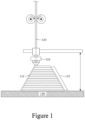
- Figure 1 shows a 3D printer in the process of manufacturing an object by means of fused deposition modelling.
- the 3D printer has a print head 110.
- Printable material 120 is extruded through a nozzle of the print head 100.
- the printable material 120 is deposited onto a build plane 140 to form a layer stack 132, comprising layers of printed material 131.
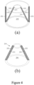
- Figures 2(a) and 2(b) show an object 210 after it has been manufactured by means of fused deposition modelling.
- the object 210 is shaped as a hollow truncated cone.
- the dashed lines are to indicate that the object 210 is built up of a sequence of layers.
- Figure 2(b) shows a cross section of the object 210 in a vertical plane.
- the cross section shows the individual layers of printed material 220 that together form a layer stack 230, which in turn constitutes the object 210.
- This cross section clearly illustrates the ribbed surface structure that is characteristic for an object made by means of fused deposition modelling.
- the layer stack 230 bounds a space 240.
- the space 240 is the interior of the hollow truncated cone.
- the layer stack 230 has an inner stack surface 231 and an outer stack surface 232.
- the inner stack surface 231 faces towards the space 240 (the interior of the hollow truncated cone) and the outer stack surface 232 faces away from the space 240 (the exterior of the hollow truncated cone).
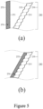
- FIG. 3(a) again shows the object 210, but now also a heat shrink 250 is provided.
- the heat shrink 250 is shaped as a right circular cylinder.
- the heat shrink 250 is a tube with a circular cross section.
- Figure 3(b) shows a cross section of the object 210 and the heat shrink 250 in a vertical plane.
- the heat shrink 250 has an inner heat shrink surface 251 and an outer heat shrink surface 252.
- the inner heat shrink surface 251 faces towards the outer stack surface 232.
- the outer heat shrink surface 252 faces away from the outer stack surface 252.
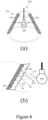
- Figure 4(a) again shows the cross section of Figure 3(b) .
- Figure 4(b) shows the object 210 after the heat shrink 250 has been shrunk to bring the inner heat shrink surface 251 in physical contact with the outer stack surface 232 and to make the heat shrink 250 conformal to the layer stack 230 (the reference numerals 232 and 251 are not shown in Figure 4(b) for the sake of clarity).
- the complete layer stack 230 is covered with the heat shrink 250.
- only a part of a layer stack may be covered with a heat shrink.
- an object may have two or more different layer stacks, of which a first sub-set of layer stacks is covered with one or more heats shrinks while a second sub-set of layer stacks is not covered with a heat shrink.
- Figure 5(a) shows a close-up of the cross section of Figure 4(a) .
- the close-up contains part of the layer stack 230, part of the space 240 and part of the heat shrink 250, with the inner stack surface 231, the outer stack surface 232, the inner heat shrink surface 251 and the outer heat shrink surface 252.
- Figure 5(b) shows the situation after applying heat to the heat shrink 250.
- the inner heat shrink surface 251 is now in physical contact with the outer stack surface 232 (the reference numerals 232 and 251 are not shown in Figure 5(b) for the sake of clarity) and the heat shrink 250 is conformal to the layer stack 230.
- the inner surface of the object 210 is still formed by the inner stack surface 231, which exhibits the characteristic ribbed surface texture.
- At least a part of the outer surface of the object 210 is now formed by the outer heat shrink surface 252 and no longer by the outer stack surface 232.
- the characteristic ribbed surface texture of the outer stack surface 232 insofar as it is covered by the heat shrink 250, is flattened or smoothed.
- the layer stack 230 is transparent. In other words, light may pass through the layer stack 230 without appreciable scattering of light.
- the layer stack does not have to be transparent, as long as it is light transmissive.
- the heat shrink 250 is arranged to provide the optical effect of reflection.
- the heat shrink 250 is light reflective.
- the heat shrink 250 does not have to be light reflective.
- the heat shrink may be arranged to provide one or more of the optical effects of refraction, diffraction, diffusion and conversion.
- the object 210 can be used as a lampshade in a lighting device.
- Figures 6(a) and 6(b) show such a lighting device 600, comprising the object 210 as a lampshade and a light source 610 that is arranged in the space 240.
- the light source 610 is arranged to emit light towards the layer stack 230 so that at least part of the light emitted by the light source 610 passes through the layer stack 230 to be reflected by the heat shrink 250.
- Figure 6(b) shows a close-up of the lighting device 600 when the light source 610 is emitting light. Light rays 611, 612 and 613 are emitted by the light source 610 and pass through the layer stack 230 before being reflected by the heat shrink 250.
- the heat shrink may be arranged to provide one or more other optical effects, such as refraction and diffusion. This is illustrated in Figures 7(a) to 7(d) .
- Figure 7(a) shows a close-up of a situation wherein the heat shrink 751 is specularly reflective.
- Figure 7(b) shows a close-up of a situation wherein the heat shrink 752 is refractive.
- Figure 7(c) shows a close-up situation wherein the heat shrink 753 is diffusive.
- a heat shrink may also arranged to provide the optical effects of diffraction and conversion.
- a heat shrink may be arranged to provide a combination of two or more of the aforementioned optical effects.
- Figure 7(d) shows a close-up situation wherein the heat shrink 754 is partially reflective and partially light transmissive.
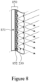
- Figure 8 shows a close-up of a situation wherein the heat shrink 850 comprises a first layer 851 and a second layer 852.
- the first layer 851 comprises a polymer material
- the second layer 852 is a metal layer.
- the second layer 852 is reflective and is in contact with the layer stack 230.
- the first layer may be in contact with the layer stack 230, in which case the first layer is preferably light transmissive.
- Figure 9 shows a close-up of a situation wherein the heat shrink 950 comprises a first layer 951 and a second layer 952.
- the first layer 951 is a decorative layer in the form of a colored layer.
- the second layer 952 is a reflective metal layer.
- the outer heat shrink surface is a surface of the first layer 951, and the inner heat shrink surface is a surface of the second layer 952.
- the first layer 951 is arranged to determine the outer appearance (color) of the object, while the second layer 952 is arranged to provide an optical effect (reflection) upon receiving light rays through the layer stack 230.
- the first layer may be a decorative layer of a different type, such as a patterned layer or a textured layer.
- the second layer may be arranged to provide a different optical effect, such as diffusion or conversion.
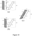
- Figures 10(a) to 10(c) show cross sectional views similar to those of Figures 4(a) and 4(b) .
- a light source 1000 is arranged relative to the layer stack 230 prior to the step of applying heat to shrink the heat shrink 250.
- the light source 1000 is integrated into the heat shrink 250.
- the light source 1000 comprises at least two light-emitting diodes (LEDs) 1010 and 1020, respectively, that are arranged to emit light in a direction towards the light transmissive layer stack 230.
- the light source may be arranged to emit light in a direction away from the layer stack 230.
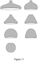
- the object 210 is shaped as a hollow truncated cone and it may be used as a lampshade. This is merely for illustration purposes.
- the object may have any suitable shape, as long as it has a light transmissive layer stack that bounds a space. Other suitable shapes for the object are illustrated in Figure 11 .
- the object may also be for use as a different component in a lighting device, such as a reflector, a diffuser or a collimator.
Landscapes
- Engineering & Computer Science (AREA)
- Manufacturing & Machinery (AREA)
- Chemical & Material Sciences (AREA)
- Materials Engineering (AREA)
- General Engineering & Computer Science (AREA)
- Physics & Mathematics (AREA)
- Mechanical Engineering (AREA)
- Optics & Photonics (AREA)
- Thermal Sciences (AREA)
- Non-Portable Lighting Devices Or Systems Thereof (AREA)
Claims (15)
- Verfahren zum Herstellen eines Objekts (210) mittels Schmelzschichtung, das Verfahren nacheinander umfassend die Schritte:- 3D-Drucken eines druckbaren Materials (120), um einen Schichtstapel (230) des gedruckten Materials (220) zu erzeugen, wobei der Schichtstapel (230) einen Raum (240) begrenzt, wobei der Schichtstapel (230) eine innere Stapeloberfläche (231) und eine äußere Stapeloberfläche (232) aufweist, wobei die innere Stapeloberfläche (231) dem Raum (240) zugewandt ist und die äußere Stapeloberfläche (232) von dem Raum (240) abgewandt ist,- Bereitstellen eines Wärmeschrumpfschlauchs (250) auf den Schichtstapel (230), wobei der Wärmeschrumpfschlauch (250) eine innere Wärmeschrumpfschlauchoberfläche (251) und eine äußere Wärmeschrumpfschlauchoberfläche (252) aufweist, wobei die innere Wärmeschrumpfschlauchoberfläche (251) der äußeren Stapeloberfläche (232) zugewandt ist und die äußere Wärmeschrumpfschlauchoberfläche (252) von der äußeren Stapeloberfläche (232) abgewandt ist, und- Anwenden von Wärme, um den Wärmeschrumpfschlauch (250) zu schrumpfen, sodass die innere Wärmeschrumpfschlauchoberfläche (251) in physischem Kontakt mit der äußeren Stapeloberfläche (232) ist und der Wärmeschrumpfschlauch (250) dem Schichtstapel (230) konform ist,wobei der Schichtstapel (230) lichtdurchlässig ist undwobei der Wärmeschrumpfschlauch (250) angeordnet ist, um einen optischen Effekt bereitzustellen, der aus der Gruppe ausgewählt ist, bestehend aus Brechung, Beugung, Reflexion, Streuung und Wandlung.
- Verfahren nach Anspruch 1, wobei der Wärmeschrumpfschlauch (250) teilweise reflektierend und teilweise lichtdurchlässig ist.
- Verfahren nach Anspruch 1, wobei der Wärmeschrumpfschlauch (250) spiegelnd reflektierend ist und/oder einen Reflexionsgrad von 85 % oder höher aufweist.
- Verfahren nach einem der Ansprüche 1 bis 3, wobei der Wärmeschrumpfschlauch (250) ein Polymermaterial umfasst und wobei das Polymermaterial mindestens eines umfasst von:- einem Lumineszenzmaterial zum Bereitstellen des optischen Effekts der Wandlung und- reflektierenden Partikeln zum Bereitstellen des optischen Effekts der Reflexion.
- Verfahren nach Anspruch 4, wobei die reflektierenden Partikel aus der Gruppe ausgewählt sind, bestehend aus Flocken, Glitzern, BaSO4-Partikeln, Al2O3-Partikeln und TiO2-Partikeln.
- Verfahren nach einem der Ansprüche 1 bis 3, wobei der Wärmeschrumpfschlauch (850) eine erste Schicht (851) und eine zweite Schicht (852) umfasst, wobei die erste Schicht (851) ein Polymermaterial umfasst und wobei die zweite Schicht (852) eine Metallschicht ist.
- Verfahren nach einem der Ansprüche 1 bis 3, wobei der Wärmeschrumpfschlauch (950) eine erste Schicht (951) und eine zweite Schicht (952) umfasst, wobei die erste Schicht (951) eine dekorative Schicht ist, die aus der Gruppe ausgewählt ist, bestehend aus farbigen Schichten, gemusterten Schichten und texturierten Schichten, wobei die zweite Schicht (952) eine optische Schicht zum Bereitstellen des optischen Effekts ist, wobei die äußere Wärmeschrumpfschlauchoberfläche eine Oberfläche der ersten Schicht (951) ist und wobei die innere Wärmeschrumpfschlauchoberfläche eine Oberfläche der zweiten Schicht (952) ist.
- Verfahren nach einem der Ansprüche 1 bis 7, wobei der Schichtstapel (230) transparent ist.
- Verfahren nach einem der Ansprüche 1 bis 8, wobei der Schichtstapel (230) angeordnet ist, um einen optischen Effekt bereitzustellen, der aus der Gruppe ausgewählt ist, bestehend aus Brechung, Beugung, Reflexion, Streuung und Wandlung.
- Verfahren nach einem der Ansprüche 1 bis 9, wobei, zwischen den Schritten des 3D-Druckens des druckbaren Materials (220), um den Schichtstapel (230) zu erzeugen und des Bereitstellens des Wärmeschrumpfschlauchs (250) auf den Schichtstapel (230), das Verfahren ferner den Schritt eines Anordnens einer Lichtquelle (1000) relativ zu dem Schichtstapel (230) umfasst, sodass, nach dem Schritt des Anwendens von Wärme, um den Wärmeschrumpfschlauch (250) zu schrumpfen, die Lichtquelle (1000) zwischen dem Wärmeschrumpfschlauch (250) und dem Schichtstapel (230) eingeschoben wird, wobei die Lichtquelle (1000) angeordnet ist, um Licht in einer Richtung zu dem Schichtstapel (230) hin und/oder in einer Richtung zu dem Wärmeschrumpfschlauch (250) hin zu emittieren.
- Verfahren nach einem der Ansprüche 1 bis 9, wobei der Wärmeschrumpfschlauch (250) eine Lichtquelle (1000), die darin integriert oder daran befestigt ist, aufweist, sodass nach dem Schritt des Anwendens von Wärme, um den Wärmeschrumpfschlauch (250) zu schrumpfen, die Lichtquelle (1000) angeordnet ist, um Licht in einer Richtung zu dem Schichtstapel (230) hin und/oder in einer Richtung von dem Schichtstapel (230) weg zu emittieren.
- Objekt (210), umfassend einen Raum (240), der über einen Schichtstapel (230) aus 3D-gedrucktem Material (220) begrenzt ist,wobei der Schichtstapel (230) eine innere Stapeloberfläche (231) und eine äußere Stapeloberfläche (232) aufweist, wobei die innere Stapeloberfläche (231) dem Raum (240) zugewandt ist und die äußere Stapeloberfläche (232) von dem Raum (240) abgewandt ist,dadurch gekennzeichnet, dassdas Objekt (210) ferner einen Wärmeschrumpfschlauch (250) umfasst, der eine innere Wärmeschrumpfschlauchoberfläche (251) und eine äußere Wärmeschrumpfschlauchoberfläche (252) aufweist, wobei die innere Wärmeschrumpfschlauchoberfläche (251) der äußeren Stapeloberfläche (232) zugewandt ist und die äußere Wärmeschrumpfschlauchoberfläche (252) von der äußeren Stapeloberfläche (232) abgewandt ist,wobei die innere Wärmeschrumpfschlauchoberfläche (251) in physischem Kontakt mit der äußeren Stapeloberfläche (232) ist und der Wärmeschrumpfschlauch (250) dem Schichtstapel (230) konform ist,wobei der Schichtstapel (230) lichtdurchlässig ist undwobei der Wärmeschrumpfschlauch (250) angeordnet ist, um einen optischen Effekt bereitzustellen, der aus der Gruppe ausgewählt ist, bestehend aus Brechung, Beugung, Reflexion, Streuung und Wandlung.
- Objekt (210) nach Anspruch 12, wobei das Objekt (210) ein Lampenschirm ist.
- Objekt (210) nach Anspruch 13, wobei das Objekt (210) ferner eine Fassung zum Aufnehmen einer Lichtquelle umfasst.
- Beleuchtungsvorrichtung (600), umfassend das Objekt (210) nach einem der Ansprüche 13 und 14, wobei die Beleuchtungsvorrichtung (600) ferner eine Lichtquelle (610), die in dem Raum (240) angeordnet ist, umfasst und wobei die Lichtquelle (610) angeordnet ist, um Licht zu dem Schichtstapel (230) hin zu emittieren, sodass mindestens ein Teil des Lichts, das über die Lichtquelle (610) emittiert wird, durch den Schichtstapel (230) hindurchgeht, um den optischen Effekt, der über den Wärmeschrumpfschlauch (250) bereitgestellt wird, zu erfahren.
Applications Claiming Priority (2)
| Application Number | Priority Date | Filing Date | Title |
|---|---|---|---|
| EP20166936.3A EP3888886A1 (de) | 2020-03-31 | 2020-03-31 | 3d-gedruckter gegenstand, der mit einem schrumpfschlauch überzogen ist |
| PCT/EP2021/057992 WO2021198096A1 (en) | 2020-03-31 | 2021-03-26 | 3d printed object covered with a heat shrink |
Publications (2)
| Publication Number | Publication Date |
|---|---|
| EP4126506A1 EP4126506A1 (de) | 2023-02-08 |
| EP4126506B1 true EP4126506B1 (de) | 2024-05-08 |
Family
ID=70108112
Family Applications (2)
| Application Number | Title | Priority Date | Filing Date |
|---|---|---|---|
| EP20166936.3A Withdrawn EP3888886A1 (de) | 2020-03-31 | 2020-03-31 | 3d-gedruckter gegenstand, der mit einem schrumpfschlauch überzogen ist |
| EP21715236.2A Active EP4126506B1 (de) | 2020-03-31 | 2021-03-26 | Verfahren zur herstellung und 3d-gedruckten objekts, mit einem schrumpfschlauch überzogen |
Family Applications Before (1)
| Application Number | Title | Priority Date | Filing Date |
|---|---|---|---|
| EP20166936.3A Withdrawn EP3888886A1 (de) | 2020-03-31 | 2020-03-31 | 3d-gedruckter gegenstand, der mit einem schrumpfschlauch überzogen ist |
Country Status (4)
| Country | Link |
|---|---|
| US (1) | US11833741B2 (de) |
| EP (2) | EP3888886A1 (de) |
| CN (1) | CN115379940A (de) |
| WO (1) | WO2021198096A1 (de) |
Families Citing this family (2)
| Publication number | Priority date | Publication date | Assignee | Title |
|---|---|---|---|---|
| CN119452294A (zh) * | 2022-06-23 | 2025-02-14 | 昕诺飞控股有限公司 | 光学组件、包括这种组件的灯具及其制造方法 |
| CN115533124B (zh) * | 2022-08-31 | 2024-07-26 | 中国地质大学(武汉) | 一种基于3d打印技术的金属透光板的制备方法 |
Family Cites Families (14)
| Publication number | Priority date | Publication date | Assignee | Title |
|---|---|---|---|---|
| US5121329A (en) | 1989-10-30 | 1992-06-09 | Stratasys, Inc. | Apparatus and method for creating three-dimensional objects |
| NZ521942A (en) * | 2000-04-14 | 2004-08-27 | S | Luminary device with phosphorescent label made of heat-shrinkable polymer |
| ATE504232T1 (de) * | 2005-11-03 | 2011-04-15 | Strategic Solutions International Llc | Isolierter flaschenbehälter |
| WO2016022449A1 (en) | 2014-08-04 | 2016-02-11 | 3M Innovative Properties Company | Finishing system for 3d printed components |
| PL3374182T3 (pl) * | 2015-11-09 | 2020-11-16 | Signify Holding B.V. | Drukowanie 3d obiektów z optycznymi powierzchniami funkcjonalnymi |
| WO2017114720A1 (en) * | 2015-12-29 | 2017-07-06 | Philips Lighting Holding B.V. | Customizable 3d-printed lighting device |
| CN109195777B (zh) * | 2016-06-02 | 2021-06-01 | 昕诺飞控股有限公司 | 用于熔融沉积建模的包括电子部件的细丝 |
| WO2018005349A1 (en) * | 2016-06-28 | 2018-01-04 | Dow Global Technologies Llc | Thermoset additive manufactured articles incorporating a phase change material and method to make them |
| US10589461B2 (en) * | 2016-09-22 | 2020-03-17 | Signify Holding B.V. | Method of using FDM to obtain specularly reflective surfaces |
| US10300660B2 (en) * | 2016-10-25 | 2019-05-28 | Covestro Deutschland Ag | Method of treating at least part of the surface of a 3D-printed article |
| WO2018077712A1 (en) * | 2016-10-31 | 2018-05-03 | Philips Lighting Holding B.V. | Method for 3d printing a 3d item with a decorative surface texture |
| CN110573321B (zh) * | 2017-04-25 | 2021-12-21 | 昕诺飞控股有限公司 | 压印的3d打印结构、打印方法、3d物品和具有3d物品的照明系统 |
| WO2018224395A1 (en) * | 2017-06-09 | 2018-12-13 | Philips Lighting Holding B.V. | Optical component for generating light effect |
| US11186112B1 (en) * | 2020-05-22 | 2021-11-30 | Innoview ARL | Synthesis of curved surface moiré |
-
2020
- 2020-03-31 EP EP20166936.3A patent/EP3888886A1/de not_active Withdrawn
-
2021
- 2021-03-26 CN CN202180026303.9A patent/CN115379940A/zh active Pending
- 2021-03-26 WO PCT/EP2021/057992 patent/WO2021198096A1/en not_active Ceased
- 2021-03-26 EP EP21715236.2A patent/EP4126506B1/de active Active
- 2021-03-26 US US17/915,207 patent/US11833741B2/en active Active
Also Published As
| Publication number | Publication date |
|---|---|
| US11833741B2 (en) | 2023-12-05 |
| CN115379940A (zh) | 2022-11-22 |
| US20230118231A1 (en) | 2023-04-20 |
| WO2021198096A1 (en) | 2021-10-07 |
| EP4126506A1 (de) | 2023-02-08 |
| EP3888886A1 (de) | 2021-10-06 |
Similar Documents
| Publication | Publication Date | Title |
|---|---|---|
| CN109414875B (zh) | 3d打印反射器及其制造方法 | |
| US12544974B2 (en) | Optical component for generating light effect | |
| JP6907201B2 (ja) | 3d印刷による光学構成要素の製造方法、光学構成要素、及び照明デバイス | |
| CN110023793B (zh) | 用于生成光效果的光学元件 | |
| CN108474527B (zh) | 可定制的3d打印照明设备 | |
| CN107709869B (zh) | 具有可定制的光束形状、光束颜色和颜色均一性的led射灯 | |
| EP4126506B1 (de) | Verfahren zur herstellung und 3d-gedruckten objekts, mit einem schrumpfschlauch überzogen | |
| US12390985B2 (en) | Method of manufacturing a 3D item by means of fused deposition modeling | |
| WO2025056458A1 (en) | A led filament lamp showing a flame effect |
Legal Events
| Date | Code | Title | Description |
|---|---|---|---|
| STAA | Information on the status of an ep patent application or granted ep patent |
Free format text: STATUS: UNKNOWN |
|
| STAA | Information on the status of an ep patent application or granted ep patent |
Free format text: STATUS: THE INTERNATIONAL PUBLICATION HAS BEEN MADE |
|
| PUAI | Public reference made under article 153(3) epc to a published international application that has entered the european phase |
Free format text: ORIGINAL CODE: 0009012 |
|
| STAA | Information on the status of an ep patent application or granted ep patent |
Free format text: STATUS: REQUEST FOR EXAMINATION WAS MADE |
|
| 17P | Request for examination filed |
Effective date: 20221031 |
|
| AK | Designated contracting states |
Kind code of ref document: A1 Designated state(s): AL AT BE BG CH CY CZ DE DK EE ES FI FR GB GR HR HU IE IS IT LI LT LU LV MC MK MT NL NO PL PT RO RS SE SI SK SM TR |
|
| DAV | Request for validation of the european patent (deleted) | ||
| DAX | Request for extension of the european patent (deleted) | ||
| GRAP | Despatch of communication of intention to grant a patent |
Free format text: ORIGINAL CODE: EPIDOSNIGR1 |
|
| STAA | Information on the status of an ep patent application or granted ep patent |
Free format text: STATUS: GRANT OF PATENT IS INTENDED |
|
| INTG | Intention to grant announced |
Effective date: 20231115 |
|
| GRAS | Grant fee paid |
Free format text: ORIGINAL CODE: EPIDOSNIGR3 |
|
| P01 | Opt-out of the competence of the unified patent court (upc) registered |
Effective date: 20240208 |
|
| GRAA | (expected) grant |
Free format text: ORIGINAL CODE: 0009210 |
|
| STAA | Information on the status of an ep patent application or granted ep patent |
Free format text: STATUS: THE PATENT HAS BEEN GRANTED |
|
| AK | Designated contracting states |
Kind code of ref document: B1 Designated state(s): AL AT BE BG CH CY CZ DE DK EE ES FI FR GB GR HR HU IE IS IT LI LT LU LV MC MK MT NL NO PL PT RO RS SE SI SK SM TR |
|
| REG | Reference to a national code |
Ref country code: GB Ref legal event code: FG4D |
|
| REG | Reference to a national code |
Ref country code: CH Ref legal event code: EP |
|
| REG | Reference to a national code |
Ref country code: DE Ref legal event code: R096 Ref document number: 602021013059 Country of ref document: DE |
|
| REG | Reference to a national code |
Ref country code: IE Ref legal event code: FG4D |
|
| REG | Reference to a national code |
Ref country code: LT Ref legal event code: MG9D |
|
| REG | Reference to a national code |
Ref country code: NL Ref legal event code: MP Effective date: 20240508 |
|
| PG25 | Lapsed in a contracting state [announced via postgrant information from national office to epo] |
Ref country code: IS Free format text: LAPSE BECAUSE OF FAILURE TO SUBMIT A TRANSLATION OF THE DESCRIPTION OR TO PAY THE FEE WITHIN THE PRESCRIBED TIME-LIMIT Effective date: 20240908 |
|
| PG25 | Lapsed in a contracting state [announced via postgrant information from national office to epo] |
Ref country code: BG Free format text: LAPSE BECAUSE OF FAILURE TO SUBMIT A TRANSLATION OF THE DESCRIPTION OR TO PAY THE FEE WITHIN THE PRESCRIBED TIME-LIMIT Effective date: 20240508 |
|
| PG25 | Lapsed in a contracting state [announced via postgrant information from national office to epo] |
Ref country code: FI Free format text: LAPSE BECAUSE OF FAILURE TO SUBMIT A TRANSLATION OF THE DESCRIPTION OR TO PAY THE FEE WITHIN THE PRESCRIBED TIME-LIMIT Effective date: 20240508 Ref country code: HR Free format text: LAPSE BECAUSE OF FAILURE TO SUBMIT A TRANSLATION OF THE DESCRIPTION OR TO PAY THE FEE WITHIN THE PRESCRIBED TIME-LIMIT Effective date: 20240508 |
|
| PG25 | Lapsed in a contracting state [announced via postgrant information from national office to epo] |
Ref country code: GR Free format text: LAPSE BECAUSE OF FAILURE TO SUBMIT A TRANSLATION OF THE DESCRIPTION OR TO PAY THE FEE WITHIN THE PRESCRIBED TIME-LIMIT Effective date: 20240809 |
|
| PG25 | Lapsed in a contracting state [announced via postgrant information from national office to epo] |
Ref country code: PT Free format text: LAPSE BECAUSE OF FAILURE TO SUBMIT A TRANSLATION OF THE DESCRIPTION OR TO PAY THE FEE WITHIN THE PRESCRIBED TIME-LIMIT Effective date: 20240909 |
|
| REG | Reference to a national code |
Ref country code: AT Ref legal event code: MK05 Ref document number: 1684651 Country of ref document: AT Kind code of ref document: T Effective date: 20240508 |
|
| PG25 | Lapsed in a contracting state [announced via postgrant information from national office to epo] |
Ref country code: NL Free format text: LAPSE BECAUSE OF FAILURE TO SUBMIT A TRANSLATION OF THE DESCRIPTION OR TO PAY THE FEE WITHIN THE PRESCRIBED TIME-LIMIT Effective date: 20240508 |
|
| PG25 | Lapsed in a contracting state [announced via postgrant information from national office to epo] |
Ref country code: ES Free format text: LAPSE BECAUSE OF FAILURE TO SUBMIT A TRANSLATION OF THE DESCRIPTION OR TO PAY THE FEE WITHIN THE PRESCRIBED TIME-LIMIT Effective date: 20240508 |
|
| PG25 | Lapsed in a contracting state [announced via postgrant information from national office to epo] |
Ref country code: AT Free format text: LAPSE BECAUSE OF FAILURE TO SUBMIT A TRANSLATION OF THE DESCRIPTION OR TO PAY THE FEE WITHIN THE PRESCRIBED TIME-LIMIT Effective date: 20240508 |
|
| PG25 | Lapsed in a contracting state [announced via postgrant information from national office to epo] |
Ref country code: PL Free format text: LAPSE BECAUSE OF FAILURE TO SUBMIT A TRANSLATION OF THE DESCRIPTION OR TO PAY THE FEE WITHIN THE PRESCRIBED TIME-LIMIT Effective date: 20240508 |
|
| PG25 | Lapsed in a contracting state [announced via postgrant information from national office to epo] |
Ref country code: LV Free format text: LAPSE BECAUSE OF FAILURE TO SUBMIT A TRANSLATION OF THE DESCRIPTION OR TO PAY THE FEE WITHIN THE PRESCRIBED TIME-LIMIT Effective date: 20240508 |
|
| PG25 | Lapsed in a contracting state [announced via postgrant information from national office to epo] |
Ref country code: PT Free format text: LAPSE BECAUSE OF FAILURE TO SUBMIT A TRANSLATION OF THE DESCRIPTION OR TO PAY THE FEE WITHIN THE PRESCRIBED TIME-LIMIT Effective date: 20240909 Ref country code: PL Free format text: LAPSE BECAUSE OF FAILURE TO SUBMIT A TRANSLATION OF THE DESCRIPTION OR TO PAY THE FEE WITHIN THE PRESCRIBED TIME-LIMIT Effective date: 20240508 Ref country code: NO Free format text: LAPSE BECAUSE OF FAILURE TO SUBMIT A TRANSLATION OF THE DESCRIPTION OR TO PAY THE FEE WITHIN THE PRESCRIBED TIME-LIMIT Effective date: 20240808 Ref country code: NL Free format text: LAPSE BECAUSE OF FAILURE TO SUBMIT A TRANSLATION OF THE DESCRIPTION OR TO PAY THE FEE WITHIN THE PRESCRIBED TIME-LIMIT Effective date: 20240508 Ref country code: LV Free format text: LAPSE BECAUSE OF FAILURE TO SUBMIT A TRANSLATION OF THE DESCRIPTION OR TO PAY THE FEE WITHIN THE PRESCRIBED TIME-LIMIT Effective date: 20240508 Ref country code: IS Free format text: LAPSE BECAUSE OF FAILURE TO SUBMIT A TRANSLATION OF THE DESCRIPTION OR TO PAY THE FEE WITHIN THE PRESCRIBED TIME-LIMIT Effective date: 20240908 Ref country code: HR Free format text: LAPSE BECAUSE OF FAILURE TO SUBMIT A TRANSLATION OF THE DESCRIPTION OR TO PAY THE FEE WITHIN THE PRESCRIBED TIME-LIMIT Effective date: 20240508 Ref country code: GR Free format text: LAPSE BECAUSE OF FAILURE TO SUBMIT A TRANSLATION OF THE DESCRIPTION OR TO PAY THE FEE WITHIN THE PRESCRIBED TIME-LIMIT Effective date: 20240809 Ref country code: FI Free format text: LAPSE BECAUSE OF FAILURE TO SUBMIT A TRANSLATION OF THE DESCRIPTION OR TO PAY THE FEE WITHIN THE PRESCRIBED TIME-LIMIT Effective date: 20240508 Ref country code: ES Free format text: LAPSE BECAUSE OF FAILURE TO SUBMIT A TRANSLATION OF THE DESCRIPTION OR TO PAY THE FEE WITHIN THE PRESCRIBED TIME-LIMIT Effective date: 20240508 Ref country code: BG Free format text: LAPSE BECAUSE OF FAILURE TO SUBMIT A TRANSLATION OF THE DESCRIPTION OR TO PAY THE FEE WITHIN THE PRESCRIBED TIME-LIMIT Effective date: 20240508 Ref country code: AT Free format text: LAPSE BECAUSE OF FAILURE TO SUBMIT A TRANSLATION OF THE DESCRIPTION OR TO PAY THE FEE WITHIN THE PRESCRIBED TIME-LIMIT Effective date: 20240508 Ref country code: RS Free format text: LAPSE BECAUSE OF FAILURE TO SUBMIT A TRANSLATION OF THE DESCRIPTION OR TO PAY THE FEE WITHIN THE PRESCRIBED TIME-LIMIT Effective date: 20240808 |
|
| PG25 | Lapsed in a contracting state [announced via postgrant information from national office to epo] |
Ref country code: DK Free format text: LAPSE BECAUSE OF FAILURE TO SUBMIT A TRANSLATION OF THE DESCRIPTION OR TO PAY THE FEE WITHIN THE PRESCRIBED TIME-LIMIT Effective date: 20240508 |
|
| PG25 | Lapsed in a contracting state [announced via postgrant information from national office to epo] |
Ref country code: EE Free format text: LAPSE BECAUSE OF FAILURE TO SUBMIT A TRANSLATION OF THE DESCRIPTION OR TO PAY THE FEE WITHIN THE PRESCRIBED TIME-LIMIT Effective date: 20240508 |
|
| PG25 | Lapsed in a contracting state [announced via postgrant information from national office to epo] |
Ref country code: CZ Free format text: LAPSE BECAUSE OF FAILURE TO SUBMIT A TRANSLATION OF THE DESCRIPTION OR TO PAY THE FEE WITHIN THE PRESCRIBED TIME-LIMIT Effective date: 20240508 |
|
| PG25 | Lapsed in a contracting state [announced via postgrant information from national office to epo] |
Ref country code: SK Free format text: LAPSE BECAUSE OF FAILURE TO SUBMIT A TRANSLATION OF THE DESCRIPTION OR TO PAY THE FEE WITHIN THE PRESCRIBED TIME-LIMIT Effective date: 20240508 Ref country code: RO Free format text: LAPSE BECAUSE OF FAILURE TO SUBMIT A TRANSLATION OF THE DESCRIPTION OR TO PAY THE FEE WITHIN THE PRESCRIBED TIME-LIMIT Effective date: 20240508 |
|
| PG25 | Lapsed in a contracting state [announced via postgrant information from national office to epo] |
Ref country code: SM Free format text: LAPSE BECAUSE OF FAILURE TO SUBMIT A TRANSLATION OF THE DESCRIPTION OR TO PAY THE FEE WITHIN THE PRESCRIBED TIME-LIMIT Effective date: 20240508 |
|
| PG25 | Lapsed in a contracting state [announced via postgrant information from national office to epo] |
Ref country code: SM Free format text: LAPSE BECAUSE OF FAILURE TO SUBMIT A TRANSLATION OF THE DESCRIPTION OR TO PAY THE FEE WITHIN THE PRESCRIBED TIME-LIMIT Effective date: 20240508 Ref country code: SK Free format text: LAPSE BECAUSE OF FAILURE TO SUBMIT A TRANSLATION OF THE DESCRIPTION OR TO PAY THE FEE WITHIN THE PRESCRIBED TIME-LIMIT Effective date: 20240508 Ref country code: RO Free format text: LAPSE BECAUSE OF FAILURE TO SUBMIT A TRANSLATION OF THE DESCRIPTION OR TO PAY THE FEE WITHIN THE PRESCRIBED TIME-LIMIT Effective date: 20240508 Ref country code: EE Free format text: LAPSE BECAUSE OF FAILURE TO SUBMIT A TRANSLATION OF THE DESCRIPTION OR TO PAY THE FEE WITHIN THE PRESCRIBED TIME-LIMIT Effective date: 20240508 Ref country code: DK Free format text: LAPSE BECAUSE OF FAILURE TO SUBMIT A TRANSLATION OF THE DESCRIPTION OR TO PAY THE FEE WITHIN THE PRESCRIBED TIME-LIMIT Effective date: 20240508 Ref country code: CZ Free format text: LAPSE BECAUSE OF FAILURE TO SUBMIT A TRANSLATION OF THE DESCRIPTION OR TO PAY THE FEE WITHIN THE PRESCRIBED TIME-LIMIT Effective date: 20240508 |
|
| PG25 | Lapsed in a contracting state [announced via postgrant information from national office to epo] |
Ref country code: IT Free format text: LAPSE BECAUSE OF FAILURE TO SUBMIT A TRANSLATION OF THE DESCRIPTION OR TO PAY THE FEE WITHIN THE PRESCRIBED TIME-LIMIT Effective date: 20240508 |
|
| REG | Reference to a national code |
Ref country code: DE Ref legal event code: R097 Ref document number: 602021013059 Country of ref document: DE |
|
| PLBE | No opposition filed within time limit |
Free format text: ORIGINAL CODE: 0009261 |
|
| STAA | Information on the status of an ep patent application or granted ep patent |
Free format text: STATUS: NO OPPOSITION FILED WITHIN TIME LIMIT |
|
| 26N | No opposition filed |
Effective date: 20250211 |
|
| PG25 | Lapsed in a contracting state [announced via postgrant information from national office to epo] |
Ref country code: SI Free format text: LAPSE BECAUSE OF FAILURE TO SUBMIT A TRANSLATION OF THE DESCRIPTION OR TO PAY THE FEE WITHIN THE PRESCRIBED TIME-LIMIT Effective date: 20240508 |
|
| PGFP | Annual fee paid to national office [announced via postgrant information from national office to epo] |
Ref country code: FR Payment date: 20250324 Year of fee payment: 5 |
|
| PGFP | Annual fee paid to national office [announced via postgrant information from national office to epo] |
Ref country code: GB Payment date: 20250325 Year of fee payment: 5 |
|
| PGFP | Annual fee paid to national office [announced via postgrant information from national office to epo] |
Ref country code: DE Payment date: 20250528 Year of fee payment: 5 |
|
| PG25 | Lapsed in a contracting state [announced via postgrant information from national office to epo] |
Ref country code: SE Free format text: LAPSE BECAUSE OF FAILURE TO SUBMIT A TRANSLATION OF THE DESCRIPTION OR TO PAY THE FEE WITHIN THE PRESCRIBED TIME-LIMIT Effective date: 20240508 |
|
| PG25 | Lapsed in a contracting state [announced via postgrant information from national office to epo] |
Ref country code: MC Free format text: LAPSE BECAUSE OF FAILURE TO SUBMIT A TRANSLATION OF THE DESCRIPTION OR TO PAY THE FEE WITHIN THE PRESCRIBED TIME-LIMIT Effective date: 20240508 |
|
| REG | Reference to a national code |
Ref country code: CH Ref legal event code: H13 Free format text: ST27 STATUS EVENT CODE: U-0-0-H10-H13 (AS PROVIDED BY THE NATIONAL OFFICE) Effective date: 20251023 |
|
| PG25 | Lapsed in a contracting state [announced via postgrant information from national office to epo] |
Ref country code: LU Free format text: LAPSE BECAUSE OF NON-PAYMENT OF DUE FEES Effective date: 20250326 |
|
| REG | Reference to a national code |
Ref country code: BE Ref legal event code: MM Effective date: 20250331 |
|
| PG25 | Lapsed in a contracting state [announced via postgrant information from national office to epo] |
Ref country code: BE Free format text: LAPSE BECAUSE OF NON-PAYMENT OF DUE FEES Effective date: 20250331 |
|
| PG25 | Lapsed in a contracting state [announced via postgrant information from national office to epo] |
Ref country code: CH Free format text: LAPSE BECAUSE OF NON-PAYMENT OF DUE FEES Effective date: 20250331 |
|
| PG25 | Lapsed in a contracting state [announced via postgrant information from national office to epo] |
Ref country code: IE Free format text: LAPSE BECAUSE OF NON-PAYMENT OF DUE FEES Effective date: 20250326 |