EP3548784B1 - Profilschelle - Google Patents
Profilschelle Download PDFInfo
- Publication number
- EP3548784B1 EP3548784B1 EP17804908.6A EP17804908A EP3548784B1 EP 3548784 B1 EP3548784 B1 EP 3548784B1 EP 17804908 A EP17804908 A EP 17804908A EP 3548784 B1 EP3548784 B1 EP 3548784B1
- Authority
- EP
- European Patent Office
- Prior art keywords
- tensioning
- clamping
- heads
- profiled clamp
- head
- Prior art date
- Legal status (The legal status is an assumption and is not a legal conclusion. Google has not performed a legal analysis and makes no representation as to the accuracy of the status listed.)
- Active
Links
Images



Classifications
-
- F—MECHANICAL ENGINEERING; LIGHTING; HEATING; WEAPONS; BLASTING
- F16—ENGINEERING ELEMENTS AND UNITS; GENERAL MEASURES FOR PRODUCING AND MAINTAINING EFFECTIVE FUNCTIONING OF MACHINES OR INSTALLATIONS; THERMAL INSULATION IN GENERAL
- F16L—PIPES; JOINTS OR FITTINGS FOR PIPES; SUPPORTS FOR PIPES, CABLES OR PROTECTIVE TUBING; MEANS FOR THERMAL INSULATION IN GENERAL
- F16L33/00—Arrangements for connecting hoses to rigid members; Rigid hose-connectors, i.e. single members engaging both hoses
- F16L33/02—Hose-clips
- F16L33/04—Hose-clips tightened by tangentially-arranged threaded pin and nut
-
- F—MECHANICAL ENGINEERING; LIGHTING; HEATING; WEAPONS; BLASTING
- F16—ENGINEERING ELEMENTS AND UNITS; GENERAL MEASURES FOR PRODUCING AND MAINTAINING EFFECTIVE FUNCTIONING OF MACHINES OR INSTALLATIONS; THERMAL INSULATION IN GENERAL
- F16L—PIPES; JOINTS OR FITTINGS FOR PIPES; SUPPORTS FOR PIPES, CABLES OR PROTECTIVE TUBING; MEANS FOR THERMAL INSULATION IN GENERAL
- F16L23/00—Flanged joints
- F16L23/04—Flanged joints the flanges being connected by members tensioned in the radial plane
- F16L23/08—Flanged joints the flanges being connected by members tensioned in the radial plane connection by tangentially arranged pin and nut
Definitions
- the invention relates to a profile clamp according to the preamble of claim 1.
- US 2004/216284 A1 , US 2008/184536 A1 and US 2010/223764 each disclose such a profile clamp.
- Profile clips are widely used to connect pipelines.
- the profile clamp is pushed over the pipeline with a tension band.
- the clamping heads of the profile clamp are then moved towards one another by tensioning the clamping device, whereby the inner diameter or the receiving space of the profile clamp is reduced and a radially inwardly directed clamping force is exerted on the pipeline.
- the pipeline can thus be clamped to another pipeline or to a clamping head.
- the profile clamp has an essentially U-shaped tension band.
- the lines to be connected have a radially protruding, circumferential flange.
- the profile clamp is positioned so that the flanges of the lines protrude into the U-shaped tensioning band.
- the legs of the U-shaped tensioning band run at an angle, so that when the tensioning band is tensioned, in addition to the radially acting tensioning force, an axial tensioning force is exerted on the flanges with respect to the lines, by which the flanges are pressed against each other so that they rest against each other, creating a seal takes place between the lines.
- the object of the invention is to provide a profile clamp with an improved stress distribution within the tensioning band, in particular in the event of temperature changes.
- the tensioning band having at each end a clamping head that protrudes essentially radially with respect to a receiving space defined by the profile clamp, each with an opening
- the tensioning device has two clamping parts and an elongated clamping element connecting the clamping parts with the clamping element extending through the openings of the clamping heads and pressing the clamping parts against the clamping heads
- the profile clamp has intermediate elements which are provided between the clamping heads and the clamping parts, the intermediate elements having recesses through which the clamping element extends extends, as well as a contact surface for contact with the clamping head, the contact surface being designed in such a way that the contact point between the intermediate element and the clamping head is at least in a clamping position in which the clamping heads are parallel to one another or inclined to one another ind, is closer to the receiving space in the radial direction than the central axis of the clamping element.
- the clamping heads are pressed against one another by the clamping device in such a way that the clamping band rests against one or more pipelines all the way around.
- the point of application i.e. the point of application of the clamping device on the clamping heads
- the lever arm between the point of application and one at the transition between the clamping heads and the clamping band intended foot point of the clamping heads is significantly shorter. This is what happens when tensioning the clamping device to less deformation of the clamping heads, so that a more effective introduction of the clamping forces into the clamping band is possible.
- the point of application of the tensioning device can also be moved closer to the base point, regardless of the shape of the tensioning device.
- the intermediate elements can be selected so that the point of application between the intermediate elements and the clamping heads is each radially closer to the base of the respective clamping head than the central axis of the clamping element.
- the tensioning heads can also be designed symmetrically, so that an alignment of the profile clamp, for example for actuation of the tensioning device, is not necessary. After pre-assembling the profile clamp, this can be mounted on the clamping heads in any orientation.
- the tensioning band is curved, for example, around the receiving space and the tensioning heads each have a section directly adjoining the respective end of the tensioning band and curved in the opposite direction to the curvature of the tensioning band, the contact points each being on the curved section of the tensioning heads.
- the intermediate elements can have a rounded contact surface so that even if the clamping head is deformed or the position of the clamping heads is changed, for example when the clamping heads are pulled together by the clamping device, the contact point lies in the radial direction below the central axis of the clamping element.
- the contact surface is convexly curved.
- the curvature of the contact surfaces is smaller than the curvature of the curved sections of the clamping heads.
- the contact surfaces also each have a protrusion protruding in the circumferential direction, the protrusion being provided further inward in the radial direction than the opening of the clamping head. Due to the projection, the contact point can be selected largely independently of the alignment of the clamping heads.
- the projection is preferably selected in such a way that even when the clamping heads are inclined away from or towards one another, only the projection rests on the respective clamping head.
- the intermediate element made of sheet metal and the projection is bent by stamping or punching out of the sheet metal.
- cooperating holding elements are preferably provided, which fix the intermediate elements in the radial direction and in a direction of rotation about the longitudinal axis of the clamping element. If the clamping heads are not aligned parallel to one another, the clamping device can be pushed towards the closer together ends of the clamping heads during clamping. If the clamping heads are inclined towards one another, for example, the clamping device could move radially outward during clamping. This would enlarge the lever arm, which could lead to higher tensions in the tensioning band. Furthermore, the clamping device could be pushed against the edge of the respective opening, which could result in a load on the material of the clamping heads in these areas.
- the intermediate elements and thus also the clamping device are fixed in the radial direction by the holding elements, so that increased stress on the clamping heads is avoided.
- the non-rotatable fixation also ensures that the intermediate elements always have the desired alignment on the clamping heads.
- part of the clamping device can also be fixed in a rotationally fixed manner on one of the intermediate elements and thus on a clamping head.
- the holding elements can each be formed, for example, by at least one recess on the intermediate element or on the clamping head and at least one projection provided on the clamping head or the intermediate element, which protrudes into the recess.
- the projection protrudes in the circumferential direction with respect to the receiving space and the recess is open in the circumferential direction.
- the intermediate elements can be fixed in a simple manner by pushing the recess onto the projection.
- the projection is bent out of the clamping head or the intermediate element, in particular stamped, which enables the projection to be produced in a simple manner.
- the intermediate element preferably has a receptacle for a filling body or a clamping part of the clamping device.
- the filler body can, for example, have a support function for the intermediate element or provide an abutment for a clamping part which enables the clamping part to be placed flat on the filler body and thus on the intermediate element.
- the filling body is held in a desired orientation in the receptacle. If a clamping part is held in the receptacle, it can be held in such a way that it is connected to the clamping element as well as tensioning of the tensioning device is possible.
- the clamping part is a nut with an internal thread, which is held in the receptacle in the circumferential direction, in the radial direction and in the direction of rotation about the longitudinal axis of the clamping element.
- a clamping part with an internal thread can be provided in one receptacle and a filler body with a cylindrical recess can be provided in the second receptacle.
- the filler body can provide a flat abutment for a head of the tensioning element, for example a screw head.
- the other intermediate element fixes the clamping part, which is designed as a nut. The tensioning device can thus be easily mounted on the tensioning strap.
- the intermediate element can also enclose the receptacle in a circumferential direction and thus have an abutment for a clamping part.
- the clamping heads are preferably designed to be inclined to one another.
- Opposite contact surfaces can be provided on the radially outer ends of the clamping heads which come into contact with one another when the clamping heads are drawn together.
- the clamping heads and the clamping band can each have a U-shaped cross section, at least in sections.
- the U-shaped cross section can be interrupted by flat sections in order to increase the flexibility of the tensioning strap.
- the U-shaped cross section can change in the radial direction in the area of the clamping head and / or in the circumferential direction in the area of the clamp band.
- the cross section can be adapted to the expected loads.
- the cross section can be adapted, for example, by adapting the length, the thickness or the shape of the base and / or the legs of the U-shaped cross section. Alternatively, the angle between the leg and the base can be changed.
- the cross-section can be different in sections or change continuously.
- a tensioning band 12 of a profile clamp 10 is shown.
- the tensioning band 12 has an essentially U-shaped cross section with two legs 14, 16 inclined relative to one another and a connecting area 18 (see also FIG Figure 2 ) and delimits a receiving space 20.
- the legs 14, 16 have several interruptions 22, so that the tensioning band 12 is designed to be more flexible.
- the clamping band 12 has two clamping heads 24, 26 which protrude radially with respect to the receiving space 20 and on which a clamping device 28 (see FIG Figures 6 and 8th ) to tension the tensioning band 12 can attack.
- the clamping device 28 has a clamping element 30 and two clamping parts 32, 34, which can be moved towards one another by the clamping element 30, whereby the clamping heads 24, 26 can be pressed against one another.
- the profile clamp 10 is used to connect two lines 36, 38 (see Figure 2 ), each of which has a radially protruding flange 40, 42 at one end.
- the lines 36, 38 are placed against one another with the flanges 40, 42 and the profile clamp 10 is placed over the two flanges 40, 42 so that the flanges 40, 42 are located in the receiving space 20.
- the tensioning band 12 is then tensioned with the tensioning device 28 in such a way that the legs 14, 16 bear against the flanges 40, 42 and press them against one another.
- the clamping heads 24, 26 are constructed symmetrically and each have at least some sections of a U-shaped cross section.
- An opening 44, 46 is provided on each clamping head 24, 26 through which the clamping element 30 of the clamping device 28 can extend.
- clamping heads 24, 26 projections 48, 50 protruding in the circumferential direction U of the clamping band 12 are also provided on the opposite sides, each of which is bent out of the sheet metal of the clamping head 24, 26.
- the clamping heads At the radially outer ends of the surfaces facing one another, the clamping heads each have a contact surface 52, 54, the contact surfaces 52, 54 being opposite one another in such a way that they can rest against one another when the tensioning band 12 is tensioned.
- the profile clamp 10 also has intermediate elements 56, 58 which are arranged between the clamping heads 24, 26 and the clamping parts 32, 34.
- the intermediate elements 56, 58 are each formed from a sheet metal by bending and have a contact surface 60, 62 for contact with the clamping heads 24, 26 and a contact 64, 66 arranged on an opposite surface.
- a clamping part 32 can be applied to the system 64.
- Recesses 68, 70 with which the intermediate elements 56, 58 can be pushed onto the projections 48, 50 on the clamping heads 24, 26 are provided on the contact surfaces 60, 62.
- Latching elements 72, 74 are provided on the projections 48, 50, each of which latches in the recess 68, 70 and prevents the intermediate element 56, 58 from slipping off the projection 48, 50.
- the projections 48, 50 and the recesses 68, 70 form each cooperating holding elements which fix the intermediate element 56, 58 in the radial direction and in a direction of rotation around the clamping element on the clamping head 24, 26.
- the intermediate elements 56, 58 also have a filler body 76, 77 which is inserted between the contact surface 60, 62 and the abutment 64, 66. Bores are provided on each of the fillers 76, 77, the contact surfaces 60, 62 and the abutments 64, 66, which form a recess 78, 79 extending through the intermediate element, through which the clamping element 30 can extend.
- tabs 80, 82 are provided which fix the filling body 76, 77 in a receptacle 84, 86 of the respective intermediate element 56, 58.
- an internal thread can be provided in the bore of a filling body 78 and the clamping element 30 has a corresponding external thread, so that the filling body 77 forms a clamping part 34.
- the second clamping part 32 is firmly connected to the clamping element 30 and preferably has a torque transmission profile.
- the filling body 77 can also have, analogously to the filling body 76, only one recess 79 through which the tensioning element 30 extends, and the tensioning element 34 is an element separate from the filling body 77 and rests against the abutment 66.
- the intermediate elements 56, 58 with the contact surfaces 60, 62 are pressed against the clamping heads 24, 26 by the clamping device 28 or the clamping parts 32. There is therefore a power transmission from the clamping device 28 or the clamping parts 32 to the intermediate elements 56, 58 and further to the clamping heads 24, 26.
- the contact surface 60, 62 of the intermediate elements 56, 58 can be seen rounded on the radially inner edge in the assembled state on the clamping band 12 and has a projection 88, 90 which protrudes in the circumferential direction to the clamping head 24, 26 in the assembled state.
- a recess 92, 94, into which the projection 88, 90 can engage, is provided on each of the clamping heads 24, 26.
- the intermediate elements 56, 58 are only in contact with the projections 88, 90 on the clamping heads 24, 26.
- the clamping part 32 lies flat against the abutment 64, so that an optimal power transmission is guaranteed.
- the contact point 96, 98 with which the intermediate elements 56, 58 rest on the clamping heads 24, 26 is therefore very close to the Base points 100, 102 of the clamping heads, which each form the transition from the clamping heads 24, 26 to the clamping band 12.
- the application point 96, 98 is in any case closer to the receiving space 20 in the radial direction of the receiving space 20 than the central axis 104 of the clamping element 30 or closer to the respective base point 100, 102 than the central axis 104 of the clamping element 30
- the bending load on the clamping heads 24, 26 is significantly reduced, so that a more uniform distribution of stress in the clamping band 12 can be achieved.
- the clamping heads 24, 26 are also designed to be inclined to one another.
- the clamping device 28 can be mounted on the clamping band 12 with any orientation.
- the intermediate elements 56, 58 define the contact points 96, 98 on the one hand , 26 takes place.
- FIGS Figures 7 and 8th A second embodiment of the intermediate elements 56, 58 is shown in FIGS Figures 7 and 8th shown.
- the structure essentially corresponds to that in Figures 5 Intermediate elements 56, 58 shown in FIG. 6. Only no system is provided for the tensioning device. The tensioning element 32 thus rests directly on the filler body 76.
- the profile clamp 10 has different cross-sectional shapes in the circumferential direction.
- the profile clamp In the area of the clamping heads ( Figure 9a ) the profile clamp has an essentially U-shaped cross section.
- the cross section In the transition area to the tensioning strap 12 or at the base points 100, 102, the cross section changes so that it is essentially U-shaped, as a result of which the depressions 92, 94 are formed.
- the cross section is essentially U-shaped, with the legs 14, 16 being at an angle to one another.
- the angle decreases, for example, from the cross section CC to the cross section ee. With the profile clamp 10 installed, this leads to a more even distribution of tension within the tensioning band 12.
- the angle of the legs 14, 16 is cc 39.6 ° in section, dd 38.1 ° in section and 34.4 ° in section ee.
- the angles can also assume other values as long as a uniform distribution of stress in the tensioning strap 12 is guaranteed.
- the angle is preferably between 45 and 30 °.
- the invention is not restricted to one of the embodiments described above, but can be modified in many ways.
- the intermediate elements 56, 58 only have to be designed so that the contact point 96, 98 between the intermediate elements 56, 58 and the clamping heads 24, 26 is each radially closer to the base 100, 102 of the respective clamping head 24, 26 than the central axis 104 of the clamping element 30 and that the contact surfaces 60, 62 each have a protrusion 88, 90 protruding in the circumferential direction U, the protrusion 88, 90 each being provided closer to the receiving space 20 in the radial direction than the openings 44, 46 of the clamping head 24, 26.
- the clamping heads 24, 26 can also have a section directly adjoining the respective end of the clamping band 20 and curved in the opposite direction to the curvature of the clamping band 20, the contact points 96, 98 each lying on these curved sections of the clamping heads 24, 26.
- the curvature of the curved sections is greater than an optionally present curvature of the contact surfaces 60, 62.
- FIGS. 11a and 11b show a second embodiment of a profile clamp.
- the structure of this profile clamp 10 corresponds essentially to the profile clamp 10 described above.
- the projections 48, 50 have no locking elements, but are instead bent radially inward at their ends. The bent ends form a hook-shaped locking means which prevents the intermediate elements 56, 58 from slipping off.
Landscapes
- Engineering & Computer Science (AREA)
- General Engineering & Computer Science (AREA)
- Mechanical Engineering (AREA)
- Clamps And Clips (AREA)
- Flanged Joints, Insulating Joints, And Other Joints (AREA)
Description
- Die Erfindung betrifft eine Profilschelle gemäß dem Oberbegriff von Anspruch 1.
US 2004/216284 A1 ,US 2008/184536 A1 undUS 2010/223764 offenbaren jeweils eine solche Profilschelle. - Profilschellen werden vielfach zum Verbinden von Rohrleitungen verwendet. Die Profilschelle wird mit einem Spannband über die Rohrleitung geschoben. Anschließend werden die Spannköpfe der Profilschelle durch Spannen der Spanneinrichtung aufeinander zu bewegt, wodurch der Innendurchmesser bzw. der Aufnahmeraum der Profilschelle verringert und eine radial nach innen gerichtete Spannkraft auf die Rohrleitung ausgeübt wird. Die Rohrleitung kann dadurch an einer weiteren Rohrleitung oder an einem Spannkopf geklemmt werden.
- Die Profilschelle hat ein im Wesentlichen U-förmiges Spannband. Die zu verbindenden Leitungen haben einen radial abstehenden, umlaufenden Flansch. Die Profilschelle wird zum Verbinden der Leitungen so positioniert, dass die Flansche der Leitungen in das U-förmige Spannband ragen. Die Schenkel des U-förmigen Spannbandes verlaufen schräg, so dass beim Spannen des Spannbandes zusätzlich zur radial wirkenden Spannkraft eine bezüglich der Leitungen axiale Spannkraft auf die Flansche ausgeübt wird, durch die die Flansche gegeneinander gedrückt werden, so dass diese aneinander anliegen, wodurch eine Abdichtung zwischen den Leitungen erfolgt.
- Durch die von der Spanneinrichtung auf die Spannköpfe ausgeübten Kräfte treten innerhalb des Spannbandes Spannungen auf, die nachteilige Einflüsse auf die Dauerhaltbarkeit haben. Insbesondere bei größeren Temperaturunterschieden können dadurch die von der Profilschelle bereitgestellten Haltekräfte negativ beeinflusst werden.
- Aufgabe der Erfindung ist es, eine Profilschelle mit einer verbesserten Spannungsverteilung innerhalb des Spannbandes, insbesondere bei Temperaturänderungen, bereitzustellen.
- Hauptmerkmale der Erfindung sind im kennzeichnenden Teil von Anspruch 1 angegeben. Ausgestaltungen sind Gegenstand der Ansprüche 2 bis 11.
- Bei einer Profilschelle mit einem Spannband und einer Spanneinrichtung, wobei das Spannband an den Enden jeweils einen bezüglich eines von der Profilschelle definierten Aufnahmeraums im Wesentlichen radial abstehenden Spannkopf mit jeweils einer Öffnung aufweist, und wobei die Spanneinrichtung zwei Spannteile sowie ein längliches, die Spannteile verbindendes Spannelement aufweist, wobei sich das Spannelement durch die Öffnungen der Spannköpfe erstreckt und die Spannteile gegen die Spannköpfe drückt, ist vorgesehen, dass die Profilschelle Zwischenelemente aufweist, die zwischen den Spannköpfen und den Spannteilen vorgesehen sind, wobei die Zwischenelemente Ausnehmungen aufweisen, durch die sich das Spannelement erstreckt, sowie eine Anlegefläche zur Anlage an den Spannkopf, wobei die Anlegefläche derart ausgebildet ist, dass der Anlegepunkt zwischen dem Zwischenelement und dem Spannkopf zumindest in einer Spannposition, in der die Spannköpfe parallel zueinander oder zueinander geneigt sind, jeweils in radialer Richtung näher am Aufnahmeraum liegt als die Mittelachse des Spannelements.
- In der Spannposition werden die Spannköpfe durch die Spanneinrichtung so gegeneinander gedrückt, dass das Spannband umlaufend an einer oder mehreren Rohrleitungen anliegt.
- Da der Anlegepunkt, also der Angriffspunkt der Spanneinrichtung an den Spannköpfen, näher am Aufnahmeraum liegt als die Mittelachse des Spannelements, werden unerwünschte Spannungen in den Spannköpfen vermieden oder zumindest reduziert, da der Hebelarm zwischen Anlegepunkt und einem jeweils am Übergang zwischen den Spannköpfen und dem Spannband vorgesehenen Fußpunkt der Spannköpfe deutlich kürzer ist. Dadurch kommt es beim Spannen der Spanneinrichtung zu geringeren Verformungen der Spannköpfe, so dass eine effektivere Einleitung der Spannkräfte in das Spannband möglich ist.
- Durch die Zwischenelemente kann zudem der Angriffspunkt der Spanneinrichtung unabhängig von der Form der Spanneinrichtung näher an den Fußpunkt verlegt werden. Insbesondere ist durch die Auswahl geeigneter Zwischenelemente die Verwendung verschiedener Spanneinrichtungen möglich, so dass eine flexible Anpassung der Profilschelle möglich ist. Unabhängig von der ausgewählten Spanneinrichtung können die Zwischenelemente jeweils so gewählt werden, dass der Anlegepunkt zwischen den Zwischenelementen und dem Spannköpfen jeweils radial näher am Fußpunkt des jeweiligen Spannkopfes liegt als die Mittelachse des Spannelements. Da die Anpassung an die Spanneinrichtung über die Zwischenelemente erfolgt, können zudem die Spannköpfe symmetrisch ausgebildet sein, so dass eine Ausrichtung der Profilschelle, beispielsweise für eine Betätigung der Spanneinrichtung, nicht erforderlich ist. Diese kann nach der Vormontage der Profilschelle in beliebiger Ausrichtung an den Spannköpfen montiert werden.
- Das Spannband ist beispielsweise um den Aufnahmeraum gekrümmt und die Spannköpfe weisen jeweils einen unmittelbar an das jeweilige Ende des Spannbandes anschließenden, gegenläufig zur Krümmung des Spannbandes gekrümmten Abschnitt auf, wobei die Anlegepunkte jeweils am gekrümmten Abschnitt der Spannköpfe liegen.
- Die Zwischenelemente können eine abgerundete Anlegefläche aufweisen, so dass auch bei einer Verformung des Spannkopfes oder einer Veränderung der Position der Spannköpfe, beispielsweise beim Zusammenziehen der Spannköpfe durch die Spanneinrichtung, der Anlegepunkt in radialer Richtung unterhalb der Mittelachse des Spannelements liegt. Insbesondere ist die Anlegefläche konvex gewölbt. Insbesondere ist die Krümmung der Anlegeflächen kleiner ist als die Krümmung der gekrümmten Abschnitte der Spannköpfe.
- Die Anlegeflächen weisen auch jeweils einen in Umfangsrichtung vorstehenden Vorsprung auf, wobei der Vorsprung jeweils in radialer Richtung weiter innen als die Öffnung des Spannkopfes vorgesehen ist. Durch den Vorsprung kann der Anlegepunkt weitestgehend unabhängig von der Ausrichtung der Spannköpfe gewählt werden. Vorzugsweise ist der Vorsprung so gewählt, dass auch bei voneinander weg oder aufeinander zu geneigten Spannköpfen ausschließlich der Vorsprung am jeweiligen Spannkopf anliegt. Beispielsweise ist das Zwischenelement aus einem Blech hergestellt und der Vorsprung ist durch Prägen oder Stanzen aus dem Blech heraus gebogen.
- An den Zwischenelementen und den Spannköpfen sind vorzugsweise zusammenwirkende Halteelemente vorgesehen, die die Zwischenelemente in radialer Richtung und in einer Drehrichtung um die Längsachse des Spannelements festlegen. Sind die Spannköpfe nicht parallel zueinander ausgerichtet, kann die Spanneinrichtung beim Spannen zu den enger zusammenliegenden Enden der Spannköpfe gedrängt werden. Sind die Spannköpfe beispielsweise aufeinander zu geneigt, könnte die Spanneinrichtung beim Spannen radial nach außen wandern. Dadurch würde der Hebelarm vergrößert, wodurch es zu höheren Spannungen im Spannband kommen könnte. Des Weiteren könnte die Spanneinrichtung gegen den Rand der jeweiligen Öffnung gedrängt werden, wodurch es zu einer Belastung des Materials der Spannköpfe in diesen Bereichen kommen könnte. Durch die Halteelemente sind die Zwischenelemente und somit auch die Spanneinrichtung in radialer Richtung festgelegt, so dass eine erhöhte Beanspruchung der Spannköpfe vermieden wird. Durch die drehfeste Fixierung ist zudem sichergestellt, dass die Zwischenelemente stets die gewünschte Ausrichtung an den Spannköpfen haben. Beispielsweise kann auch ein Teil der Spanneinrichtung an einem der Zwischenelemente und somit an einem Spannkopf drehfest fixiert werden.
- Die Halteelemente können beispielsweise jeweils durch zumindest eine Ausnehmung am Zwischenelement oder am Spannkopf und zumindest einen am Spannkopf oder dem Zwischenelement vorgesehenen Vorsprung, der in die Ausnehmung ragt, gebildet sein. Insbesondere ragt der Vorsprung bezüglich des Aufnahmeraums in Umfangsrichtung vor und die Ausnehmung ist in Umfangsrichtung offen. Die Zwischenelemente können auf einfache Weise durch Aufschieben der Ausnehmung auf den Vorsprung festgelegt werden.
- Beispielsweise ist der Vorsprung aus dem Spannkopf oder dem Zwischenelement herausgebogen, insbesondere gestanzt, wodurch eine einfache Herstellung des Vorsprunges möglich ist.
- Das Zwischenelement weist vorzugsweise eine Aufnahme für einen Füllkörper oder ein Spannteil der Spanneinrichtung auf. Der Füllkörper kann beispielsweise eine Stützfunktion für das Zwischenelement aufweisen oder eine Anlage für ein Spannteil bereitstellen, die ein flächiges Anlegen des Spannteils am Füllkörper und somit am Zwischenelement ermöglicht. Der Füllkörper wird in der Aufnahme in einer gewünschten Orientierung gehalten. Wird ein Spannteil in der Aufnahme gehalten, kann dieses so gehalten werden, so dass ein Verbinden mit dem Spannelement sowie ein Spannen der Spanneinrichtung möglich ist. Beispielsweise ist das Spannteil eine Mutter mit einem Innengewinde, die in der Aufnahme in Umfangsrichtung, in radialer Richtung sowie in Drehrichtung um die Längsachse des Spannelements gehalten wird.
- Beispielsweise kann in einer Aufnahme ein Spannteil mit einem Innengewinde und in der zweiten Aufnahme ein Füllkörper mit einer zylindrischen Ausnehmung vorgesehen sein. Der Füllkörper kann eine ebene Anlage für einen Kopf des Spannelements, beispielsweise einen Schraubenkopf, bereitstellen. Das andere Zwischenelement fixiert das als Mutter ausgebildete Spannteil. Somit kann die Spanneinrichtung einfach am Spannband montiert werden.
- Das Zwischenelement kann die Aufnahme auch in einer Umfangsrichtung umschließen und somit eine Anlage für ein Spannteil aufweisen.
- Vorzugsweise sind die Spannköpfe zueinander geneigt ausgebildet.
- An den an radial äußeren Enden der Spannköpfe können einander gegenüberliegende Kontaktflächen vorgesehen sein, die beim Zusammenziehen der Spannköpfe miteinander in Anlage gelangen.
- Die Spannköpfe und das Spannband können jeweils zumindest abschnittsweise einen U-förmigen Querschnitt aufweisen. Der U-förmige Querschnitt kann von ebenen Abschnitten unterbrochen sein, um die Flexibilität des Spannbandes zu erhöhen.
- Der U-förmige Querschnitt kann sich im Bereich des Spannkopfes in radialer Richtung und/oder im Bereich des Schellenbandes in Umfangsrichtung verändern. Beispielsweise kann der Querschnitt an die zu erwartenden Belastungen angepasst werden. Der Querschnitt kann beispielsweise durch Anpassung der Länge, der Dicke oder der Form der Basis und/oder der Schenkel des U-förmigen Querschnitts angepasst werden. Alternativ kann der Winkel zwischen den Schenkel und der Basis verändert werden. Der Querschnitt kann abschnittsweise unterschiedlich sein oder sich kontinuierlich ändern.
- Weitere Merkmale, Einzelheiten und Vorteile der Erfindung ergeben sich aus dem Wortlaut der Ansprüche sowie aus der folgenden Beschreibung von Ausführungsbeispielen anhand der Zeichnungen. Es zeigen:
- Fig. 1
- ein Spannband einer erfindungsgemäßen Profilschelle;
- Fig. 2
- eine schematische Darstellung einer Rohrleitungsbaugruppe mit einer Profilschelle;
- Fig. 3
- eine Detailansicht des Spannkopfes der Profilschelle aus
Fig. 1 ; - Fig. 4
- eine zweite Detailansicht des Spannkopfes der Profilschelle aus
Fig. 1 ; - Fig. 5
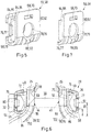
- eine erste Ausführungsform eines Zwischenelements zur Verwendung mit dem Spannband aus den
Fig. 3 und 4 ; - Fig. 6
- Eine Teilansicht einer Profilschelle mit dem Spannband aus
Fig. 1 und dem Zwischenelement ausFigur 5 ; - Fig. 7
- eine zweite Ausführungsform eines Zwischenelements zur Verwendung mit dem Spannband aus
Fig. 1 ; und - Fig. 8
- eine Teilansicht einer Profilschelle mit dem Spannband aus
Fig. 1 und dem Zwischenelement ausFig. 7 ; - Fig. 9a bis 9e
- Schnittansichten durch die Profilschelle in den Schnitten a-a bis e-e aus
Fig. 1 ; - Fig. 10
- eine zweite Ausführungsform einer Profilschelle; und
- Fig. 11a und 11b
- Detailansichten des Spannkopfes der Profilschelle aus
Fig. 10 . - In
Figur 1 ist ein Spannband 12 einer Profilschelle 10 gezeigt. Das Spannband 12 hat einen im Wesentlichen U-förmigen Querschnitt mit zwei relativ zueinander geneigten Schenkel 14, 16 sowie einem Verbindungsbereich 18 (siehe auchFigur 2 ) und begrenzt einen Aufnahmeraum 20. Die Schenkel 14, 16 weisen mehrere Unterbrechungen 22 auf, so dass das Spannband 12 flexibler ausgebildet ist. Des Weiteren weist das Spannband 12 zwei bezüglich des Aufnahmeraums 20 radial abstehende Spannköpfe 24, 26 auf, an welchen eine Spanneinrichtung 28 (sieheFiguren 6 und8 ) zum Spannen des Spannbandes 12 angreifen kann. - Die Spanneinrichtung 28 weist ein Spannelement 30 sowie zwei Spannteile 32, 34 auf, die durch das Spannelement 30 aufeinander zu bewegt werden können, wodurch die Spannköpfe 24, 26 gegeneinander gedrückt werden können.
- Die Profilschelle 10 dient zum Verbinden von zwei Leitungen 36, 38 (siehe
Figur 2 ), die jeweils an einem Ende einen radial abstehenden Flansch 40, 42 aufweisen. Die Leitungen 36, 38 werden mit den Flansche 40, 42 aneinander angelegt und die Profilschelle 10 über die beiden Flansche 40, 42 gelegt, so dass sich die Flansche 40, 42 im Aufnahmeraum 20 befinden. Anschließend wird das Spannband 12 mit der Spanneinrichtung 28 so gespannt, dass die Schenkel 14, 16 an den Flanschen 40, 42 anliegen und diese gegeneinander drücken. - Die Spannköpfe 24, 26 sind symmetrisch aufgebaut und weisen jeweils zumindest abschnittsweise einen U-förmigen Querschnitt auf. An jedem Spannkopf 24, 26 ist eine Öffnung 44, 46 vorgesehen, durch die sich das Spannelement 30 der Spanneinrichtung 28 erstrecken kann.
- An den Spannköpfen 24, 26 sind des Weiteren jeweils auf den einander abgewandten Seiten in Umfangsrichtung U des Spannbandes 12 abstehende Vorsprünge 48, 50 vorgesehen, die jeweils aus dem Blech des Spannkopfes 24, 26 herausgebogen sind. An den radial äußeren Enden der einander zugewandten Flächen weisen die Spannköpfe jeweils eine Kontaktfläche 52, 54 auf, wobei sich die Kontaktflächen 52, 54 so gegenüberliegen, dass diese beim Spannen des Spannbandes 12 aneinander anliegen können.
- Die Profilschelle 10 weist des Weiteren Zwischenelemente 56, 58 auf, die zwischen den Spannköpfen 24, 26 und den Spannteilen 32, 34 angeordnet sind. Die Zwischenelemente 56, 58 sind jeweils aus einem Blech durch Umbiegen gebildet und weisen eine Anlegefläche 60, 62 zur Anlage an den Spannköpfen 24, 26 sowie eine auf einer entgegengesetzten Fläche angeordnete Anlage 64, 66 auf. An der Anlage 64 kann, wie im Folgenden erläutert wird, ein Spannteil 32 angelegt werden.
- An den Anlegeflächen 60, 62 sind Ausnehmungen 68, 70 vorgesehen, mit welchen die Zwischenelemente 56, 58 auf die Vorsprünge 48, 50 an den Spannköpfen 24, 26 aufgeschoben werden können. An den Vorsprüngen 48, 50 sind jeweils Rastelemente 72, 74 vorgesehen, die jeweils in der Ausnehmung 68, 70 verrasten und ein Abrutschen des Zwischenelements 56, 58 vom Vorsprung 48, 50 verhindern. Die Vorsprünge 48, 50 und die Ausnehmungen 68, 70 bilden jeweils zusammenwirkende Halteelemente, die das Zwischenelement 56, 58 jeweils in radialer Richtung und in einer Drehrichtung um das Spannelement am Spannkopf 24, 26 festlegen.
- Die Zwischenelemente 56, 58 weisen des Weiteren einen Füllkörper 76, 77 auf, der zwischen der Anlegefläche 60, 62 und der Anlage 64, 66 eingelegt ist. An den Füllkörpern 76, 77, den Anlegeflächen 60, 62 sowie den Anlagen 64, 66 sind jeweils Bohrungen vorgesehen, die eine sich durch das Zwischenelement erstreckende Ausnehmung 78, 79 bilden, durch die sich das Spannelement 30 erstrecken kann. An den Zwischenelementen 56, 58 sind jeweils Laschen 80, 82 vorgesehen, die den Füllkörper 76, 77 in einer Aufnahme 84, 86 des jeweiligen Zwischenelements 56, 58 fixieren.
- Beispielsweise kann in der Bohrung eines Füllkörpers 78 ein Innengewinde vorgesehen sein und das Spannelement 30 weist ein korrespondierendes Außengewinde auf, so dass der Füllkörper 77 ein Spannteil 34 bildet. Das zweite Spannteil 32 ist fest mit dem Spannelement 30 verbunden und weist vorzugsweise ein Drehmomentübertragungsprofil auf.
- Alternativ kann der Füllkörper 77 auch analog zum Füllkörper 76 lediglich eine Ausnehmung 79 aufweisen, durch die sich das Spannelement 30 erstreckt, und das Spannelement 34 ist ein vom Füllkörper 77 separates Element, das an der Anlage 66 anliegt.
- Durch die Spanneinrichtung 28 bzw. die Spannteile 32 werden die Zwischenelemente 56, 58 mit den Anlegeflächen 60, 62 gegen die Spannköpfe 24, 26 gedrückt. Es erfolgt also eine Kraftübertragung von der Spanneinrichtung 28 bzw. den Spannteilen 32 auf die Zwischenelemente 56, 58 und weiter auf die Spannköpfe 24, 26.
- Wie in
Figur 5 zu sehen ist die Anlegefläche 60, 62 der Zwischenelemente 56, 58 an der in montiertem Zustand am Spannband 12 radial inneren Kante abgerundet und weist einen Vorsprung 88, 90 auf, der in montiertem Zustand in Umfangsrichtung zum Spannkopf 24, 26 vorsteht. An den Spannköpfen 24, 26 ist jeweils eine Vertiefung 92, 94 vorgesehen, in die der Vorsprung 88, 90 eingreifen kann. - Wie in
Figur 6 zu sehen ist, liegen die Zwischenelemente 56, 58 lediglich mit den Vorsprüngen 88, 90 an den Spannköpfen 24, 26 an. Das Spannteil 32 liegt flächig an der Anlage 64 an, so dass eine optimale Kraftübertragung gewährleistet ist. Der Anlegepunkt 96, 98, mit dem die Zwischenelemente 56, 58 an den Spannköpfen 24, 26 anliegen, liegt dadurch sehr nah an den Fußpunkten 100, 102 der Spannköpfe, die jeweils den Übergang von den Spannköpfen 24, 26 zum Spannband 12 bilden. Wie inFigur 6 zu sehen ist, liegt der Anlegepunkt 96, 98 in jedem Fall in radialer Richtung des Aufnahmeraums 20 näher am Aufnahmeraum 20 als die Mittelachse 104 des Spannelements 30 bzw. näher am jeweiligen Fußpunkt 100, 102 als die Mittelachse 104 des Spannelements 30. Dadurch wird die Biegebelastung auf die Spannköpfe 24, 26 deutlicher reduziert, so dass eine gleichmäßigere Spannungsverteilung im Spannband 12 erreicht werden kann. Um diesen Effekt zu verstärken, sind die Spannköpfe 24, 26 des Weiteren zueinander geneigt ausgebildet. - Da die Spannköpfe 24, 26 symmetrisch ausgebildet sind, kann die Spanneinrichtung 28 mit einer beliebigen Ausrichtung am Spannband 12 montiert werden. Durch die Zwischenelemente 56, 58 erfolgt zum einen die Festlegung der Anlegepunkte 96, 98. Zum anderen liegen die Spanneinrichtung 28 bzw. die Spannteile 32 flächig an den Zwischenelementen 56, 58 an, so dass eine verbesserte Kräfteübertragung von der Spanneinrichtung 28 auf die Spannköpfe 24, 26 erfolgt.
- Eine zweite Ausführungsform der Zwischenelemente 56, 58 ist in den
Figuren 7 und8 gezeigt. Der Aufbau entspricht im Wesentlichen den in denFiguren 5 un6 gezeigten Zwischenelementen 56, 58. Es ist lediglich keine Anlage für die Spanneinrichtung vorgesehen. Das Spannelement 32 liegt somit direkt am Füllkörper 76 an. - Wie in den
Figuren 9a bis 9e zu sehen ist, weist die Profilschelle 10 in Umfangsrichtung verschiedene Querschnittsformen auf. Im Bereich der Spannköpfe (Figur 9a ) hat die Profilschelle einen im Wesentlichen U-förmigen Querschnitt. Im Übergangsbereich zum Spannband 12 bzw. an den Fußpunkten 100, 102 verändert sich der Querschnitt, so dass dieser im Wesentlichen U-förmig ist, wodurch die Vertiefungen 92, 94 gebildet sind. - Im Bereich des Spannbandes 12 ist der Querschnitt im Wesentlichen U-förmig, wobei die Schenkel 14, 16 in einem Winkel zueinander stehen. Der Winkel nimmt beispielsweise vom Querschnitt C-C bis zum Querschnitt e-e ab. Dies führt bei montierter Profilschelle 10 zu einer gleichmäßigeren Spannungsverteilung innerhalb des Spannbandes 12. Beispielsweise beträgt der Winkel der Schenkel 14, 16 im Schnitt c-c 39,6°, im Schnitt d-d 38,1° und im Schnitt e-e 34,4°. Die Winkel können aber auch andere Werte annehmen, solange eine gleichmäßige Spannungsverteilung im spannband 12 gewährleistet ist. Vorzugsweise beträgt der Winkel zwischen 45 und 30°.
- Die Erfindung ist nicht auf eine der vorbeschriebenen Ausführungsformen beschränkt, sondern in vielfältiger Weise abwandelbar. Die Zwischenelemente 56, 58 müssen lediglich so ausgebildet sein, dass der Anlegepunkt 96, 98 zwischen den Zwischenelementen 56, 58 und den Spannköpfen 24, 26 jeweils radial näher am Fußpunkt 100, 102 des jeweiligen Spannkopfes 24, 26 liegt als die Mittelachse 104 des Spannelements 30 und, dass die Anlegeflächen 60, 62 jeweils einen in Umfangsrichtung U vorstehenden Vorsprung 88, 90 aufweisen, wobei der Vorsprung 88, 90 jeweils in radialer Richtung näher am Aufnahmeraum 20 als die Öffnungen 44, 46 des Spannkopfes 24, 26 vorgesehen ist.
- Beispielsweise können die Spannköpfe 24, 26 auch einen jeweils unmittelbar an das jeweilige Ende des Spannbandes 20 anschließenden, gegenläufig zur Krümmung des Spannbandes 20 gekrümmten Abschnitt aufweisen, wobei die Anlegepunkte 96, 98 jeweils an diesen gekrümmten Abschnitten der Spannköpfe 24, 26 liegen. Insbesondere ist die Krümmung der gekrümmten Abschnitte größer als eine optional vorhandene Krümmung der Anlegeflächen 60, 62.
- In den
Figuren 10 sowie 11a und 11b ist eine zweite Ausführungsform einer Profilschelle gezeigt. Der Aufbau dieser Profilschelle 10 entspricht im Wesentlichen der vorstehend beschriebenen Profilschelle 10. Die Vorsprünge 48, 50 weisen aber keine Rastelemente auf, sondern sind an ihrem Ende jeweils radial nach innen umgebogen. Die umgebogenen Enden bilden ein hakenförmiges Arretiermittel, das ein Abrutschen der Zwischenelemente 56, 58 verhindert.Bezugszeichenliste 10 Profilschelle 62 Anlegefläche 12 Spannband 64 Anlage 14 Schenkel 66 Anlage 16 Schenkel 68 Ausnehmungen 18 Verbindungsbereich 70 Ausnehmungen 20 Aufnahmeraum 72 Rastelemente 22 Unterbrechungen 74 Rastelemente 24 Spannkopf 76 Füllkörper 26 Spannkopf 77 Füllkörper 28 Spanneinrichtung 78 Ausnehmung 30 Spannelement 79 Ausnehmung 32 Spannteil 80 Laschen 34 Spannteil36 Leitungen 82 Laschen 38 Leitungen 84 Aufnahme 40 Flansch 86 Aufnahme 42 Flansch 88 Vorsprung 44 Öffnung 90 Vorsprung 46 Öffnung 92 Vertiefung 48 Vorsprünge 94 Vertiefung 50 Vorsprünge 96 Anlegepunkt 52 Kontaktfläche 98 Anlegepunkte 54 Kontaktfläche 100 Fußpunkt 56 Zwischenelemente 102 Fußpunkt 58 Zwischenelemente 104 Mittelachse 60 Anlegefläche
Claims (11)
- Profilschelle (10), mit einem Spannband (12) und einer Spanneinrichtung (28), wobei das Spannband (12) an den Enden jeweils einen bezüglich eines von der Profilschelle (10) definierten Aufnahmeraums (20) im Wesentlichen radial abstehenden Spannkopf (24, 26) mit jeweils einer Öffnung (44, 46) aufweist, und wobei die Spanneinrichtung (28) zwei Spannteile (32, 34) sowie ein längliches, die Spannteile (32, 34) verbindendes Spannelement (30) aufweist, wobei sich das Spannelement (30) durch die Öffnungen (44, 46) der Spannköpfe (24, 26) erstreckt und die Spannteile (32, 34) gegen die Spannköpfe (24, 26) drückt, dadurch gekennzeichnet, dass die Profilschelle (10) Zwischenelemente (56, 58) aufweist, die zwischen den Spannköpfen (24, 26) und den Spannteilen (32, 34) vorgesehen sind, wobei die Zwischenelemente (56, 58) Ausnehmungen (78, 79) aufweisen, durch die sich das Spannelement (30) erstreckt, sowie eine Anlegefläche (60, 62) zur Anlage an den Spannkopf (24, 26), wobei die Anlegefläche (60, 62) derart ausgebildet ist, dass der Anlegepunkt (96, 98) zwischen dem Zwischenelement (56, 58) und dem Spannkopf (24, 26) zumindest in einer Spannposition, in der die Spannköpfe (24, 26) parallel zueinander oder zueinander geneigt sind, jeweils in radialer Richtung näher am Aufnahmeraum (20) liegt als die Mittelachse (104) des Spannelements (30), und wobei die Anlegeflächen (60, 62) jeweils einen in Umfangsrichtung (U) vorstehenden Vorsprung (88, 90) aufweisen, wobei der Vorsprung (88, 90) jeweils in radialer Richtung näher am Aufnahmeraum (20) als die Öffnungen (44, 46) des Spannkopfes (24, 26) vorgesehen ist.
- Profilschelle nach Anspruch 1, dadurch gekennzeichnet, dass das Spannband (12) um den Aufnahmeraum (20) gekrümmt ist und die Spannköpfe (24, 26) jeweils einen unmittelbar an das jeweilige Ende des Spannbandes (12) anschließenden, gegenläufig zur Krümmung des Spannbandes (12) gekrümmten Abschnitt aufweisen, wobei die Anlegepunkte (96, 98) jeweils am gekrümmten Abschnitt des Spannkopfes (24, 26) liegen.
- Profilschelle nach einem der Ansprüche 1 und 2, dadurch gekennzeichnet, dass die Zwischenelemente (56, 58) jeweils eine abgerundete Anlegefläche (60, 62) aufweisen, wobei die Krümmung der Anlegeflächen (60, 62) insbesondere kleiner ist als die Krümmung der gekrümmten Abschnitte der Spannköpfe (24, 26).
- Profilschelle nach einem der Ansprüche 1 bis 3, dadurch gekennzeichnet, dass an den Zwischenelementen (56, 58) und den Spannköpfen (24, 26) zusammenwirkende Halteelemente (48, 50, 68, 70) vorgesehen sind, die die Zwischenelemente (56, 58) in radialer Richtung und in einer Drehrichtung um die Längsachse des Spannelements (30) festlegen.
- Profilschelle nach Anspruch 4, dadurch gekennzeichnet, dass die Halteelemente (48, 50, 68, 70) jeweils durch zumindest eine Ausnehmung (68, 70) am Zwischenelement (56, 58) oder am Spannkopf (24, 26) und zumindest einen am Spannkopf (24, 26) oder dem Zwischenelement (56, 58) vorgesehenen Vorsprung (48, 50), der in die Ausnehmung (68, 70) ragt, gebildet sind.
- Profilschelle nach Anspruch 5, dadurch gekennzeichnet, dass der Vorsprung (48, 50) aus dem Spannkopf (24, 26) herausgebogen ist.
- Profilschelle nach einem der vorhergehenden Ansprüche, dadurch gekennzeichnet, dass das Zwischenelement (56, 58) eine Aufnahme (84, 86) für einen Füllkörper (76, 77) oder ein Spannteil (32, 34) der Spanneinrichtung (28) aufweist.
- Profilschelle nach Anspruch 7, dadurch gekennzeichnet, dass in einer Aufnahme (86) ein Spannteil (34) mit einem Innengewinde und in der zweiten Aufnahme (84) ein Füllkörper (76) mit einer zylindrischen Ausnehmung vorgesehen ist.
- Profilschelle nach einem der vorhergehenden Ansprüche, dadurch gekennzeichnet, dass die Zwischenelement (56, 58) jeweils eine Anlage (64, 66) für ein Spannteil (32, 34) aufweisen.
- Profilschelle nach einem der vorhergehenden Ansprüche, dadurch gekennzeichnet, dass die Spannköpfe (24, 26) zueinander geneigt ausgebildet sind.
- Profilschelle nach einem der vorhergehenden Ansprüche, dadurch gekennzeichnet, dass an den an radial äußeren Enden der Spannköpfe (24, 26) einander gegenüberliegende Kontaktflächen (52, 54) vorgesehen sind.
Applications Claiming Priority (2)
| Application Number | Priority Date | Filing Date | Title |
|---|---|---|---|
| DE102016123388.9A DE102016123388B4 (de) | 2016-12-02 | 2016-12-02 | Profilschelle |
| PCT/EP2017/080755 WO2018099940A1 (de) | 2016-12-02 | 2017-11-29 | Profilschelle |
Publications (3)
| Publication Number | Publication Date |
|---|---|
| EP3548784A1 EP3548784A1 (de) | 2019-10-09 |
| EP3548784B1 true EP3548784B1 (de) | 2021-10-20 |
| EP3548784B8 EP3548784B8 (de) | 2022-01-19 |
Family
ID=60480327
Family Applications (1)
| Application Number | Title | Priority Date | Filing Date |
|---|---|---|---|
| EP17804908.6A Active EP3548784B8 (de) | 2016-12-02 | 2017-11-29 | Profilschelle |
Country Status (11)
| Country | Link |
|---|---|
| US (1) | US10890284B2 (de) |
| EP (1) | EP3548784B8 (de) |
| JP (1) | JP6831014B2 (de) |
| KR (1) | KR102285857B1 (de) |
| CN (1) | CN109964071B (de) |
| BR (1) | BR112019010695A2 (de) |
| CA (1) | CA3043150A1 (de) |
| DE (1) | DE102016123388B4 (de) |
| ES (1) | ES2900023T3 (de) |
| MX (1) | MX2019006309A (de) |
| WO (1) | WO2018099940A1 (de) |
Families Citing this family (7)
| Publication number | Priority date | Publication date | Assignee | Title |
|---|---|---|---|---|
| DE102017213879A1 (de) | 2017-08-09 | 2019-02-14 | Bayerische Motoren Werke Aktiengesellschaft | Schellenelement |
| DE102018116959A1 (de) * | 2018-07-12 | 2020-01-16 | Norma Germany Gmbh | Profilschelle |
| US11566733B2 (en) | 2019-07-31 | 2023-01-31 | Norma U.S. Holding Llc | Joint assembly, v-clamp, and end flanges |
| KR102334190B1 (ko) | 2019-11-29 | 2021-12-03 | 주식회사케이베츠 | 원형부재 보강용 클램프 장치, 그 시공방법, 원형부재 연결용 클램프 장치 및 그 시공방법 |
| KR102373470B1 (ko) | 2020-01-21 | 2022-03-14 | 주식회사케이베츠 | 원형부재 보강용 힌지 적용 클램프 장치, 그 시공방법, 원형부재 연결용 힌지 적용 클램프 장치 및 그 시공방법 |
| DE102020113297A1 (de) | 2020-05-15 | 2021-11-18 | Norma Germany Gmbh | Profilschelle zum Verbinden zweier rohrförmiger Körper |
| US20230323988A1 (en) * | 2022-04-06 | 2023-10-12 | Norma U.S. Holding Llc | Ball joint pipe clamp with retention tab |
Family Cites Families (13)
| Publication number | Priority date | Publication date | Assignee | Title |
|---|---|---|---|---|
| US4056273A (en) | 1976-12-08 | 1977-11-01 | Cassel Thomas Richard | Coupling for pipe lap joints |
| CA1298861C (en) * | 1986-11-17 | 1992-04-14 | Scott T. Cassel | Band clamp with improved clamping arrangement |
| US6796004B2 (en) * | 2001-09-14 | 2004-09-28 | Donaldson Company, Inc. | Exhaust system clamp |
| US20040216284A1 (en) * | 2001-09-14 | 2004-11-04 | Belisle John I | Exhaust system clamp |
| US6877191B2 (en) * | 2001-09-17 | 2005-04-12 | Dwws, Llc | Band clamp |
| US7052052B2 (en) * | 2003-03-13 | 2006-05-30 | Donaldson Company, Inc. | Sealing gasket for a clamp |
| FR2884563B1 (fr) | 2005-04-13 | 2011-03-18 | Caillau Ets | Dispositif de serrage a oreilles de serrage renforcees |
| FR2902175B1 (fr) * | 2006-06-09 | 2016-02-19 | Caillau Ets | Collier de serrage |
| FR2915537B1 (fr) * | 2007-04-24 | 2012-07-20 | Caillau Ets | Dispositif de serrage |
| US7997626B2 (en) * | 2009-08-06 | 2011-08-16 | Krausz Industries Development Ltd | Pipe coupling with auxiliary clamp |
| IL209938A (en) * | 2010-12-12 | 2014-06-30 | Eliezer Krausz | Mounting clamp with bushing for clamping element |
| DE102011009536B4 (de) * | 2011-01-27 | 2013-09-19 | Norma Germany Gmbh | Spannschelle |
| US9835277B2 (en) * | 2015-12-10 | 2017-12-05 | Eliezer Krausz Industrial Development Ltd. | Axial-restraint pipe coupling with individual grip elements |
-
2016
- 2016-12-02 DE DE102016123388.9A patent/DE102016123388B4/de active Active
-
2017
- 2017-11-29 CA CA3043150A patent/CA3043150A1/en not_active Abandoned
- 2017-11-29 CN CN201780071816.5A patent/CN109964071B/zh not_active Expired - Fee Related
- 2017-11-29 EP EP17804908.6A patent/EP3548784B8/de active Active
- 2017-11-29 MX MX2019006309A patent/MX2019006309A/es unknown
- 2017-11-29 BR BR112019010695A patent/BR112019010695A2/pt not_active IP Right Cessation
- 2017-11-29 US US16/465,752 patent/US10890284B2/en not_active Expired - Fee Related
- 2017-11-29 JP JP2019529937A patent/JP6831014B2/ja not_active Expired - Fee Related
- 2017-11-29 KR KR1020197019006A patent/KR102285857B1/ko not_active Expired - Fee Related
- 2017-11-29 ES ES17804908T patent/ES2900023T3/es active Active
- 2017-11-29 WO PCT/EP2017/080755 patent/WO2018099940A1/de not_active Ceased
Also Published As
| Publication number | Publication date |
|---|---|
| DE102016123388A1 (de) | 2018-06-07 |
| KR102285857B1 (ko) | 2021-08-04 |
| US10890284B2 (en) | 2021-01-12 |
| KR20190087612A (ko) | 2019-07-24 |
| CA3043150A1 (en) | 2018-06-07 |
| ES2900023T3 (es) | 2022-03-15 |
| JP2020501090A (ja) | 2020-01-16 |
| CN109964071A (zh) | 2019-07-02 |
| WO2018099940A1 (de) | 2018-06-07 |
| BR112019010695A2 (pt) | 2019-10-01 |
| US20190390806A1 (en) | 2019-12-26 |
| JP6831014B2 (ja) | 2021-02-17 |
| EP3548784B8 (de) | 2022-01-19 |
| MX2019006309A (es) | 2020-07-24 |
| CN109964071B (zh) | 2021-10-08 |
| EP3548784A1 (de) | 2019-10-09 |
| DE102016123388B4 (de) | 2019-01-10 |
Similar Documents
| Publication | Publication Date | Title |
|---|---|---|
| DE102016123388B4 (de) | Profilschelle | |
| EP2049807B1 (de) | Vorrichtung zum befestigen eines anbauteiles und eines trägerteiles in einem abstand voneinander | |
| EP3423745B1 (de) | Profilschelle | |
| EP3423742B1 (de) | Profilschelle | |
| EP3423744B1 (de) | Vorpositionierer für eine profilschelle und verbindungsanordnung mit einem derartigen vorpositionierer | |
| EP3308065B1 (de) | Schelle | |
| EP3308066B1 (de) | Schelle mit schellenband und vorpositionierer | |
| EP3583341B1 (de) | Schelle | |
| EP2500587A1 (de) | Befestigungsvorrichtung zur Anordnung an einer Montageschiene | |
| DE102010052782A1 (de) | Fahrzeuginsassenrückhaltesystem für ein Fahrzeug und Dichtungselement | |
| EP2910749A1 (de) | Profilschelle | |
| EP2481939A1 (de) | Spannelement | |
| DE102012221228A1 (de) | Toleranzausgleichsvorrichtung | |
| EP2171336B1 (de) | Rohrverbindung mit einem gehäuse einer armatur | |
| WO2003107418A1 (de) | Kühlkörper | |
| EP3788288A1 (de) | Schelle | |
| EP2281136B1 (de) | Steckverbindung für fluid-leitungen | |
| EP1526620B3 (de) | Kabelverschraubung mit variablem Schirmkontaktelement | |
| EP1686294B1 (de) | Schaltgabel mit Gleitschuhring und entsprechende Gleitschuhanordnung | |
| WO2016087333A1 (de) | Spannfutter | |
| DE19944131B4 (de) | Klemmring | |
| DE1056878B (de) | Befestigungsglied mit unverlierbar zugeordnetem Federring | |
| DE10217750B4 (de) | Schelle mit geschlitzten Bandschlaufen zum Einhängen eines Verschlusses | |
| WO2003062694A1 (de) | Rohrpresskupplung | |
| DE20105250U1 (de) | Flachdichtung |
Legal Events
| Date | Code | Title | Description |
|---|---|---|---|
| STAA | Information on the status of an ep patent application or granted ep patent |
Free format text: STATUS: UNKNOWN |
|
| STAA | Information on the status of an ep patent application or granted ep patent |
Free format text: STATUS: THE INTERNATIONAL PUBLICATION HAS BEEN MADE |
|
| PUAI | Public reference made under article 153(3) epc to a published international application that has entered the european phase |
Free format text: ORIGINAL CODE: 0009012 |
|
| STAA | Information on the status of an ep patent application or granted ep patent |
Free format text: STATUS: REQUEST FOR EXAMINATION WAS MADE |
|
| 17P | Request for examination filed |
Effective date: 20190614 |
|
| AK | Designated contracting states |
Kind code of ref document: A1 Designated state(s): AL AT BE BG CH CY CZ DE DK EE ES FI FR GB GR HR HU IE IS IT LI LT LU LV MC MK MT NL NO PL PT RO RS SE SI SK SM TR |
|
| AX | Request for extension of the european patent |
Extension state: BA ME |
|
| DAV | Request for validation of the european patent (deleted) | ||
| DAX | Request for extension of the european patent (deleted) | ||
| GRAP | Despatch of communication of intention to grant a patent |
Free format text: ORIGINAL CODE: EPIDOSNIGR1 |
|
| STAA | Information on the status of an ep patent application or granted ep patent |
Free format text: STATUS: GRANT OF PATENT IS INTENDED |
|
| INTG | Intention to grant announced |
Effective date: 20210611 |
|
| GRAS | Grant fee paid |
Free format text: ORIGINAL CODE: EPIDOSNIGR3 |
|
| GRAA | (expected) grant |
Free format text: ORIGINAL CODE: 0009210 |
|
| STAA | Information on the status of an ep patent application or granted ep patent |
Free format text: STATUS: THE PATENT HAS BEEN GRANTED |
|
| AK | Designated contracting states |
Kind code of ref document: B1 Designated state(s): AL AT BE BG CH CY CZ DE DK EE ES FI FR GB GR HR HU IE IS IT LI LT LU LV MC MK MT NL NO PL PT RO RS SE SI SK SM TR |
|
| REG | Reference to a national code |
Ref country code: GB Ref legal event code: FG4D Free format text: NOT ENGLISH |
|
| REG | Reference to a national code |
Ref country code: CH Ref legal event code: EP |
|
| REG | Reference to a national code |
Ref country code: IE Ref legal event code: FG4D Free format text: LANGUAGE OF EP DOCUMENT: GERMAN |
|
| REG | Reference to a national code |
Ref country code: DE Ref legal event code: R096 Ref document number: 502017011791 Country of ref document: DE |
|
| REG | Reference to a national code |
Ref country code: AT Ref legal event code: REF Ref document number: 1440224 Country of ref document: AT Kind code of ref document: T Effective date: 20211115 |
|
| REG | Reference to a national code |
Ref country code: CH Ref legal event code: PK Free format text: BERICHTIGUNG B8 |
|
| RAP4 | Party data changed (patent owner data changed or rights of a patent transferred) |
Owner name: NORMA GERMANY GMBH |
|
| PGFP | Annual fee paid to national office [announced via postgrant information from national office to epo] |
Ref country code: ES Payment date: 20211201 Year of fee payment: 5 |
|
| REG | Reference to a national code |
Ref country code: LT Ref legal event code: MG9D |
|
| REG | Reference to a national code |
Ref country code: NL Ref legal event code: MP Effective date: 20211020 |
|
| PGFP | Annual fee paid to national office [announced via postgrant information from national office to epo] |
Ref country code: IT Payment date: 20211129 Year of fee payment: 5 |
|
| REG | Reference to a national code |
Ref country code: ES Ref legal event code: FG2A Ref document number: 2900023 Country of ref document: ES Kind code of ref document: T3 Effective date: 20220315 |
|
| PG25 | Lapsed in a contracting state [announced via postgrant information from national office to epo] |
Ref country code: RS Free format text: LAPSE BECAUSE OF FAILURE TO SUBMIT A TRANSLATION OF THE DESCRIPTION OR TO PAY THE FEE WITHIN THE PRESCRIBED TIME-LIMIT Effective date: 20211020 Ref country code: LT Free format text: LAPSE BECAUSE OF FAILURE TO SUBMIT A TRANSLATION OF THE DESCRIPTION OR TO PAY THE FEE WITHIN THE PRESCRIBED TIME-LIMIT Effective date: 20211020 Ref country code: FI Free format text: LAPSE BECAUSE OF FAILURE TO SUBMIT A TRANSLATION OF THE DESCRIPTION OR TO PAY THE FEE WITHIN THE PRESCRIBED TIME-LIMIT Effective date: 20211020 Ref country code: BG Free format text: LAPSE BECAUSE OF FAILURE TO SUBMIT A TRANSLATION OF THE DESCRIPTION OR TO PAY THE FEE WITHIN THE PRESCRIBED TIME-LIMIT Effective date: 20220120 |
|
| PG25 | Lapsed in a contracting state [announced via postgrant information from national office to epo] |
Ref country code: IS Free format text: LAPSE BECAUSE OF FAILURE TO SUBMIT A TRANSLATION OF THE DESCRIPTION OR TO PAY THE FEE WITHIN THE PRESCRIBED TIME-LIMIT Effective date: 20220220 Ref country code: SK Free format text: LAPSE BECAUSE OF FAILURE TO SUBMIT A TRANSLATION OF THE DESCRIPTION OR TO PAY THE FEE WITHIN THE PRESCRIBED TIME-LIMIT Effective date: 20211020 Ref country code: SE Free format text: LAPSE BECAUSE OF FAILURE TO SUBMIT A TRANSLATION OF THE DESCRIPTION OR TO PAY THE FEE WITHIN THE PRESCRIBED TIME-LIMIT Effective date: 20211020 Ref country code: PT Free format text: LAPSE BECAUSE OF FAILURE TO SUBMIT A TRANSLATION OF THE DESCRIPTION OR TO PAY THE FEE WITHIN THE PRESCRIBED TIME-LIMIT Effective date: 20220221 Ref country code: PL Free format text: LAPSE BECAUSE OF FAILURE TO SUBMIT A TRANSLATION OF THE DESCRIPTION OR TO PAY THE FEE WITHIN THE PRESCRIBED TIME-LIMIT Effective date: 20211020 Ref country code: NO Free format text: LAPSE BECAUSE OF FAILURE TO SUBMIT A TRANSLATION OF THE DESCRIPTION OR TO PAY THE FEE WITHIN THE PRESCRIBED TIME-LIMIT Effective date: 20220120 Ref country code: NL Free format text: LAPSE BECAUSE OF FAILURE TO SUBMIT A TRANSLATION OF THE DESCRIPTION OR TO PAY THE FEE WITHIN THE PRESCRIBED TIME-LIMIT Effective date: 20211020 Ref country code: LV Free format text: LAPSE BECAUSE OF FAILURE TO SUBMIT A TRANSLATION OF THE DESCRIPTION OR TO PAY THE FEE WITHIN THE PRESCRIBED TIME-LIMIT Effective date: 20211020 Ref country code: HR Free format text: LAPSE BECAUSE OF FAILURE TO SUBMIT A TRANSLATION OF THE DESCRIPTION OR TO PAY THE FEE WITHIN THE PRESCRIBED TIME-LIMIT Effective date: 20211020 Ref country code: GR Free format text: LAPSE BECAUSE OF FAILURE TO SUBMIT A TRANSLATION OF THE DESCRIPTION OR TO PAY THE FEE WITHIN THE PRESCRIBED TIME-LIMIT Effective date: 20220121 |
|
| REG | Reference to a national code |
Ref country code: CH Ref legal event code: PL |
|
| REG | Reference to a national code |
Ref country code: DE Ref legal event code: R097 Ref document number: 502017011791 Country of ref document: DE |
|
| PG25 | Lapsed in a contracting state [announced via postgrant information from national office to epo] |
Ref country code: SM Free format text: LAPSE BECAUSE OF FAILURE TO SUBMIT A TRANSLATION OF THE DESCRIPTION OR TO PAY THE FEE WITHIN THE PRESCRIBED TIME-LIMIT Effective date: 20211020 Ref country code: RO Free format text: LAPSE BECAUSE OF FAILURE TO SUBMIT A TRANSLATION OF THE DESCRIPTION OR TO PAY THE FEE WITHIN THE PRESCRIBED TIME-LIMIT Effective date: 20211020 Ref country code: MC Free format text: LAPSE BECAUSE OF FAILURE TO SUBMIT A TRANSLATION OF THE DESCRIPTION OR TO PAY THE FEE WITHIN THE PRESCRIBED TIME-LIMIT Effective date: 20211020 Ref country code: LU Free format text: LAPSE BECAUSE OF NON-PAYMENT OF DUE FEES Effective date: 20211129 Ref country code: EE Free format text: LAPSE BECAUSE OF FAILURE TO SUBMIT A TRANSLATION OF THE DESCRIPTION OR TO PAY THE FEE WITHIN THE PRESCRIBED TIME-LIMIT Effective date: 20211020 Ref country code: DK Free format text: LAPSE BECAUSE OF FAILURE TO SUBMIT A TRANSLATION OF THE DESCRIPTION OR TO PAY THE FEE WITHIN THE PRESCRIBED TIME-LIMIT Effective date: 20211020 Ref country code: CZ Free format text: LAPSE BECAUSE OF FAILURE TO SUBMIT A TRANSLATION OF THE DESCRIPTION OR TO PAY THE FEE WITHIN THE PRESCRIBED TIME-LIMIT Effective date: 20211020 Ref country code: BE Free format text: LAPSE BECAUSE OF NON-PAYMENT OF DUE FEES Effective date: 20211130 |
|
| REG | Reference to a national code |
Ref country code: BE Ref legal event code: MM Effective date: 20211130 |
|
| PLBE | No opposition filed within time limit |
Free format text: ORIGINAL CODE: 0009261 |
|
| STAA | Information on the status of an ep patent application or granted ep patent |
Free format text: STATUS: NO OPPOSITION FILED WITHIN TIME LIMIT |
|
| 26N | No opposition filed |
Effective date: 20220721 |
|
| PG25 | Lapsed in a contracting state [announced via postgrant information from national office to epo] |
Ref country code: IE Free format text: LAPSE BECAUSE OF NON-PAYMENT OF DUE FEES Effective date: 20211129 Ref country code: AL Free format text: LAPSE BECAUSE OF FAILURE TO SUBMIT A TRANSLATION OF THE DESCRIPTION OR TO PAY THE FEE WITHIN THE PRESCRIBED TIME-LIMIT Effective date: 20211020 |
|
| PG25 | Lapsed in a contracting state [announced via postgrant information from national office to epo] |
Ref country code: SI Free format text: LAPSE BECAUSE OF FAILURE TO SUBMIT A TRANSLATION OF THE DESCRIPTION OR TO PAY THE FEE WITHIN THE PRESCRIBED TIME-LIMIT Effective date: 20211020 |
|
| PGFP | Annual fee paid to national office [announced via postgrant information from national office to epo] |
Ref country code: FR Payment date: 20221123 Year of fee payment: 6 |
|
| PG25 | Lapsed in a contracting state [announced via postgrant information from national office to epo] |
Ref country code: CY Free format text: LAPSE BECAUSE OF FAILURE TO SUBMIT A TRANSLATION OF THE DESCRIPTION OR TO PAY THE FEE WITHIN THE PRESCRIBED TIME-LIMIT Effective date: 20211020 |
|
| PG25 | Lapsed in a contracting state [announced via postgrant information from national office to epo] |
Ref country code: LI Free format text: LAPSE BECAUSE OF NON-PAYMENT OF DUE FEES Effective date: 20220701 Ref country code: HU Free format text: LAPSE BECAUSE OF FAILURE TO SUBMIT A TRANSLATION OF THE DESCRIPTION OR TO PAY THE FEE WITHIN THE PRESCRIBED TIME-LIMIT; INVALID AB INITIO Effective date: 20171129 Ref country code: CH Free format text: LAPSE BECAUSE OF NON-PAYMENT OF DUE FEES Effective date: 20220701 |
|
| PG25 | Lapsed in a contracting state [announced via postgrant information from national office to epo] |
Ref country code: IT Free format text: LAPSE BECAUSE OF NON-PAYMENT OF DUE FEES Effective date: 20221129 |
|
| REG | Reference to a national code |
Ref country code: ES Ref legal event code: FD2A Effective date: 20240102 |
|
| REG | Reference to a national code |
Ref country code: AT Ref legal event code: MM01 Ref document number: 1440224 Country of ref document: AT Kind code of ref document: T Effective date: 20221129 |
|
| PG25 | Lapsed in a contracting state [announced via postgrant information from national office to epo] |
Ref country code: ES Free format text: LAPSE BECAUSE OF NON-PAYMENT OF DUE FEES Effective date: 20221130 |
|
| PG25 | Lapsed in a contracting state [announced via postgrant information from national office to epo] |
Ref country code: ES Free format text: LAPSE BECAUSE OF NON-PAYMENT OF DUE FEES Effective date: 20221130 Ref country code: AT Free format text: LAPSE BECAUSE OF NON-PAYMENT OF DUE FEES Effective date: 20221129 |
|
| PG25 | Lapsed in a contracting state [announced via postgrant information from national office to epo] |
Ref country code: MK Free format text: LAPSE BECAUSE OF FAILURE TO SUBMIT A TRANSLATION OF THE DESCRIPTION OR TO PAY THE FEE WITHIN THE PRESCRIBED TIME-LIMIT Effective date: 20211020 |
|
| PG25 | Lapsed in a contracting state [announced via postgrant information from national office to epo] |
Ref country code: TR Free format text: LAPSE BECAUSE OF FAILURE TO SUBMIT A TRANSLATION OF THE DESCRIPTION OR TO PAY THE FEE WITHIN THE PRESCRIBED TIME-LIMIT Effective date: 20211020 |
|
| PG25 | Lapsed in a contracting state [announced via postgrant information from national office to epo] |
Ref country code: MT Free format text: LAPSE BECAUSE OF FAILURE TO SUBMIT A TRANSLATION OF THE DESCRIPTION OR TO PAY THE FEE WITHIN THE PRESCRIBED TIME-LIMIT Effective date: 20211020 |
|
| PG25 | Lapsed in a contracting state [announced via postgrant information from national office to epo] |
Ref country code: FR Free format text: LAPSE BECAUSE OF NON-PAYMENT OF DUE FEES Effective date: 20231130 |
|
| PG25 | Lapsed in a contracting state [announced via postgrant information from national office to epo] |
Ref country code: FR Free format text: LAPSE BECAUSE OF NON-PAYMENT OF DUE FEES Effective date: 20231130 |
|
| PGFP | Annual fee paid to national office [announced via postgrant information from national office to epo] |
Ref country code: DE Payment date: 20251128 Year of fee payment: 9 |
|
| PGFP | Annual fee paid to national office [announced via postgrant information from national office to epo] |
Ref country code: GB Payment date: 20251127 Year of fee payment: 9 |