EP3548189B1 - Applikationseinheit - Google Patents
Applikationseinheit Download PDFInfo
- Publication number
- EP3548189B1 EP3548189B1 EP17788215.6A EP17788215A EP3548189B1 EP 3548189 B1 EP3548189 B1 EP 3548189B1 EP 17788215 A EP17788215 A EP 17788215A EP 3548189 B1 EP3548189 B1 EP 3548189B1
- Authority
- EP
- European Patent Office
- Prior art keywords
- nozzle
- sensing device
- application unit
- unit
- component
- Prior art date
- Legal status (The legal status is an assumption and is not a legal conclusion. Google has not performed a legal analysis and makes no representation as to the accuracy of the status listed.)
- Active
Links
Images


Classifications
-
- B—PERFORMING OPERATIONS; TRANSPORTING
- B05—SPRAYING OR ATOMISING IN GENERAL; APPLYING FLUENT MATERIALS TO SURFACES, IN GENERAL
- B05C—APPARATUS FOR APPLYING FLUENT MATERIALS TO SURFACES, IN GENERAL
- B05C5/00—Apparatus in which liquid or other fluent material is projected, poured or allowed to flow on to the surface of the work
- B05C5/02—Apparatus in which liquid or other fluent material is projected, poured or allowed to flow on to the surface of the work the liquid or other fluent material being discharged through an outlet orifice by pressure, e.g. from an outlet device in contact or almost in contact, with the work
- B05C5/0208—Apparatus in which liquid or other fluent material is projected, poured or allowed to flow on to the surface of the work the liquid or other fluent material being discharged through an outlet orifice by pressure, e.g. from an outlet device in contact or almost in contact, with the work for applying liquid or other fluent material to separate articles
- B05C5/0212—Apparatus in which liquid or other fluent material is projected, poured or allowed to flow on to the surface of the work the liquid or other fluent material being discharged through an outlet orifice by pressure, e.g. from an outlet device in contact or almost in contact, with the work for applying liquid or other fluent material to separate articles only at particular parts of the articles
- B05C5/0216—Apparatus in which liquid or other fluent material is projected, poured or allowed to flow on to the surface of the work the liquid or other fluent material being discharged through an outlet orifice by pressure, e.g. from an outlet device in contact or almost in contact, with the work for applying liquid or other fluent material to separate articles only at particular parts of the articles by relative movement of article and outlet according to a predetermined path
-
- B—PERFORMING OPERATIONS; TRANSPORTING
- B05—SPRAYING OR ATOMISING IN GENERAL; APPLYING FLUENT MATERIALS TO SURFACES, IN GENERAL
- B05C—APPARATUS FOR APPLYING FLUENT MATERIALS TO SURFACES, IN GENERAL
- B05C5/00—Apparatus in which liquid or other fluent material is projected, poured or allowed to flow on to the surface of the work
- B05C5/02—Apparatus in which liquid or other fluent material is projected, poured or allowed to flow on to the surface of the work the liquid or other fluent material being discharged through an outlet orifice by pressure, e.g. from an outlet device in contact or almost in contact, with the work
- B05C5/0204—Apparatus in which liquid or other fluent material is projected, poured or allowed to flow on to the surface of the work the liquid or other fluent material being discharged through an outlet orifice by pressure, e.g. from an outlet device in contact or almost in contact, with the work for applying liquid or other fluent material to the edges of essentially flat articles
-
- B—PERFORMING OPERATIONS; TRANSPORTING
- B05—SPRAYING OR ATOMISING IN GENERAL; APPLYING FLUENT MATERIALS TO SURFACES, IN GENERAL
- B05C—APPARATUS FOR APPLYING FLUENT MATERIALS TO SURFACES, IN GENERAL
- B05C5/00—Apparatus in which liquid or other fluent material is projected, poured or allowed to flow on to the surface of the work
- B05C5/02—Apparatus in which liquid or other fluent material is projected, poured or allowed to flow on to the surface of the work the liquid or other fluent material being discharged through an outlet orifice by pressure, e.g. from an outlet device in contact or almost in contact, with the work
- B05C5/0254—Coating heads with slot-shaped outlet
- B05C5/0262—Coating heads with slot-shaped outlet adjustable in width, i.e. having lips movable relative to each other in order to modify the slot width, e.g. to close it
-
- B—PERFORMING OPERATIONS; TRANSPORTING
- B05—SPRAYING OR ATOMISING IN GENERAL; APPLYING FLUENT MATERIALS TO SURFACES, IN GENERAL
- B05C—APPARATUS FOR APPLYING FLUENT MATERIALS TO SURFACES, IN GENERAL
- B05C17/00—Hand tools or apparatus using hand held tools, for applying liquids or other fluent materials to, for spreading applied liquids or other fluent materials on, or for partially removing applied liquids or other fluent materials from, surfaces
- B05C17/005—Hand tools or apparatus using hand held tools, for applying liquids or other fluent materials to, for spreading applied liquids or other fluent materials on, or for partially removing applied liquids or other fluent materials from, surfaces for discharging material from a reservoir or container located in or on the hand tool through an outlet orifice by pressure without using surface contacting members like pads or brushes
- B05C17/00503—Details of the outlet element
- B05C17/00516—Shape or geometry of the outlet orifice or the outlet element
Definitions
- the present invention relates to an application unit for applying viscous material to a component edge, in particular one that varies in width.
- the invention further relates to an end effector with such an application unit and a manipulator with such an end effector and/or such an application unit.
- an application unit with a nozzle for applying the material to the component edge with an outlet opening that is adjustable in width, it is possible to variably adapt the nozzle width to the width of the component edge and in particular to a varying width of a component edge.
- the application unit now also has a first probe with a contact surface for contact with the component and a second probe with a contact surface for contact with the component, wherein the first probe and the second probe can be pre-tensioned in opposite directions with a pre-tensioning arrangement, a particularly simple, compact and cost-effective guidance of the nozzle relative to the component edge is possible.
- Pre-tensioned in opposite directions is to be understood here and preferably in such a way that the vectors of the pre-tensioning force of the probes each have at least one component that is oriented in opposite directions.
- the proposal also provides that the width of the outlet opening can be adjusted depending on the distance between the contact surface of the first button and the contact surface of the second button. This makes it possible to create an application unit that is particularly compact and structurally simple in the area of the nozzle's outlet opening, which also enables the application of viscous material to component edges in the area of narrow component cutouts.
- buttons in particular the first button
- one of the buttons, in particular the first button is arranged fixedly on the nozzle. It is also preferred if one of the buttons, in particular the first button, is formed in one piece (integral) with the nozzle. This enables a particularly compact design of the nozzle in the region of its outlet opening.
- one of the buttons in particular the second button, is mounted so that it can move relative to the nozzle, in particular so that it can be moved linearly.
- mounting in or on the nozzle has proven to be advantageous. In this way, the width of the nozzle can be easily adapted to the width of the component edge.
- a nozzle that is particularly compact in the area of the outlet opening can be realized by the nozzle forming a nozzle unit with the first button and/or the second button (claim 4), wherein preferably the first button and/or the second button provides or provide a section of the outlet opening and the width of the outlet opening can be adjusted by a relative movement of one button to the other button.
- the probes can slide along both sides of the component edge and easily limit the application of the viscous material to the component edge.
- the application unit is designed such that the width of the outlet opening can be or is adapted, in particular continuously, to the width of the component edge.
- the width of the outlet opening corresponds essentially, in particular exactly, to the width of the component edge.
- the outlet opening of the nozzle can preferably be closed by one of the buttons, in particular the second button, or the buttons.
- the outlet opening of the nozzle is preferably closed by a relative movement of one of the buttons, in particular the second button, to the nozzle or by a relative movement of the buttons to the nozzle before and/or after the application of the viscous material. In this way, unwanted dripping of the viscous material from the outlet opening when the application unit is moved to or from the component edge can be avoided.
- the application unit has a receiving unit for receiving the nozzle and/or the nozzle unit.
- the nozzle and/or the nozzle unit can be detached from the receiving unit at an interface. It is particularly preferred if the nozzle or the nozzle unit can be detached from the receiving unit without tools. This means that the nozzle or the nozzle unit can be designed as a disposable part. There is no need for time-consuming cleaning of the nozzle after application. It can be replaced easily and inexpensively. The application unit's operating times can be increased accordingly, since cleaning is no longer necessary when it is thrown away or can be carried out separately from the application unit.
- the pretensioning arrangement has at least one pretensioning unit, in particular a first pretensioning unit, for pretensioning one of the buttons in a first direction.
- the pretensioning arrangement additionally has a second pretensioning unit for pretensioning the other button in an opposite direction.
- the nozzle can be at least partially, preferably predominantly, particularly preferably completely, made of plastic, in particular polyethylene
- the button can be at least partially, preferably predominantly, particularly preferably completely, made of plastic, in particular polyethylene
- the nozzle unit can be at least partially, preferably predominantly, particularly preferably completely, made of plastic, in particular polyethylene.
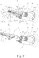
- a proposed manipulator 1 with a proposed end effector 2 and a proposed application unit 3 is shown.
- the manipulator 1 can be in particular an industrial robot with at least three axes or at least four axes or a gantry robot with at least three axes or at least four axes.
- the manipulator 1 shown in Fig. 1 Manipulator 1 shown has six axes.
- the application unit 3 serves to apply a viscous material 4 to a component edge 5 of a component 6, which in particular varies in width B K and/or position.
- a component edge is in the Fig. 2a shown.
- the component edge 5 is here an end face of the component 6, in particular an end face of a plate-shaped section of the component 6.
- the width B K of the component edge 5 is the width transverse to the direction of travel V B of the component edge 5.
- the component 5 is a structural component, in particular a motor vehicle structural component and/or an aircraft structural component, for example a stringer.
- the component 5 can in particular also be an assembly of different parts 6a, 6b, as shown in the Fig. 3
- the component 5 can be a composite component, preferably a composite component made of carbon fiber reinforced plastic (CFRP) and/or a composite component made of glass fiber reinforced aluminum, so-called glare.
- CFRP carbon fiber reinforced plastic
- the viscous material 4 can in particular be an adhesive and/or a sealing material.
- the viscous material is preferably a two-component epoxy. This is preferably mixed before exiting the outlet opening 8. It can be mixed, as is the case in the exemplary embodiment, before entering the application unit 3. Alternatively, however, it can also be mixed in the application unit, in particular in the nozzle 7, or when entering the application unit 3, in particular in the nozzle 7.
- the application unit 3 has a nozzle 7 for applying the material to the component edge 5 with an outlet opening 8 adjustable in width B A.
- the outlet opening 8 is here and preferably formed at an angle to the longitudinal extension of the nozzle 7.
- the outlet opening 8 is arranged in a direction orthogonal to the longitudinal extension L of the nozzle 7, as shown in the embodiment. This allows component edges 5 of narrow recesses to be flexibly sealed in a simple manner. In principle, however, according to an alternative embodiment, it is also conceivable for the outlet opening 8 to point in the direction of the longitudinal extension L of the nozzle 7.
- the application unit 3 further comprises, as proposed, a first button 9 with a contact surface 9a for contact with the component 6, in particular with a first side of the component 6 adjacent to the component edge 5, and a second button 10 with a contact surface 10a for contact with the component 6, in particular with a second side adjacent to the component edge 5, opposite the first side.
- the first probe 9 and the second probe 10 can be pre-tensioned in opposite directions onto the component 6 by means of a pre-tensioning arrangement 11.
- the width B A of the outlet opening 8 can now be adjusted depending on the distance of the contact surface 9a of the first button 9 and the contact surface 10a of the second button 10.
- This enables particularly simple, energy-saving application to the component edge 5.
- this also enables a particularly compact design of the nozzle 7 in the area of the outlet opening 8, whereby the viscous material 4 can also be applied to the component edges 5 of narrow cutouts.
- a structurally simple and therefore cost-effective design is made possible.
- the term "can be prestressed in opposite directions” is to be understood here and preferably to mean that the vectors V 1 , V 2 of the prestressing force of the buttons 9, 10 each have at least one component which is oriented in opposite directions.
- the vectors V 1 , V 2 of the prestressing force are preferably arranged parallel to the width direction of the nozzle 7.
- buttons 9, 10 are located here as in the Fig. 2 shown opposite each other. Accordingly, the two buttons 9, 10 can be pre-tensioned here and preferably also on each other.
- one of the probes 9 can be arranged fixedly on the nozzle 7.
- the probe 9 is formed in one piece (integral) with the nozzle 7. It forms a probe section of the nozzle 7.
- the probe 9 can also have a roller, which can facilitate sliding of the probe 9 along the component 6 when applying the viscous material 4.
- the second button 10 is mounted so that it can move relative to the nozzle 7.
- the second button 10 is mounted so that it can move linearly in the nozzle 7.
- An alternative preferred embodiment provides that the second button 10 is mounted so that it can move, in particular move linearly, on the nozzle 7.
- the second probe 10 is designed as a sliding block which can be moved in a translational manner.
- the probe 10 can also have a roller which makes it easier for the probe 10 to slide along the component 6 when applying the viscous material 4.
- both buttons 9, 10 can be mounted so as to be movable relative to the nozzle 7, in particular so as to be linearly displaceable. Preferably These are then mounted in or on the nozzle 7 and/or both are designed as previously described for the second button 10.
- the nozzle 7 forms a nozzle unit 12 with the first button 9 and/or the second button 10.
- the first button 9 and the second button 10 each provide a section of the outlet opening 8.
- the width B A of the outlet opening 8 can thus be adjusted by a relative movement of one button 9, 10 to the other button 9, 10, as shown in the Fig. 3 shown in the enlargements.
- the nozzle unit 12 has a receiving area 13 for receiving the component edge 5 of the component 6 when applying the viscous material 4 to the component edge 5. This is limited here by the first button 9 and the second button 10 when applying the viscous material 4 to the component edge 8 in the width direction of the outlet opening 8.
- the application unit 3 is designed in such a way that the width B A of the outlet opening 8 can be adapted, in particular continuously, to the width B K of the component edge 5 or can be adapted during application.
- the adaptation takes place passively, i.e. without the targeted control of an actuator to set the change.
- the application unit 3 has a receiving unit 13 for receiving the nozzle unit 12.
- the nozzle unit 12 can be detached from the receiving unit 13 at an interface 14.
- the nozzle unit 12 can be detached from the receiving unit 13 without tools.
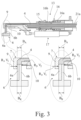
- the interface 14 is designed here as a quick-release fastener and can be easily removed from a locking mechanism on the receiving unit 13 by moving a sleeve 15, in particular against a spring preload. It should be noted here that the nozzle 7, when it is locked in the receiving unit 13, is firmly connected to it.
- the preload arrangement 11 has at least one, in particular a first, preload unit 16 for preloading one of the buttons 9 in a first direction Ri.
- the first pre-tensioning unit 16 is arranged here on the receiving unit 13. It acts here between a fastening flange 13a for fastening the application unit 3 to the manipulator 1 and the nozzle 7. In the exemplary embodiment, it has a spiral spring element 16a as a spring element. Alternatively, however, the first pre-tensioning unit 16 can also have a pneumatic spring element and/or a leaf spring element. Furthermore, the first pre-tensioning unit 16 can have a further spring element, in particular a spring element designed as a spiral spring element 16b, which is pre-tensioned against the spring element 16a of the first pre-tensioning unit 16. This spring element 16b can simultaneously pre-tension the sleeve 15 into its locking position.
- the preload of the first probe 9 is generated by means of the first preload unit 16.
- the component edge 5 is approached with the nozzle 7 and then the first probe 9 is preloaded against the component 6 by tensioning the first preload unit 16 and preloading the first probe 9 onto the component 5 by a manipulator movement in the direction of the second probe 10.
- the pretensioning arrangement 16 further comprises a second pretensioning unit 17 for pretensioning the other button 10 in the opposite direction R 2 .
- a second pretensioning unit 17 for pretensioning the other button 10 in the opposite direction R 2 .
- the directions are arranged parallel to the width direction of the outlet opening 8.
- the second pre-tensioning unit 17 is also arranged here and preferably on the receiving unit 13. It acts here between the fastening flange 13a and the second button 10. Alternatively, the second pre-tensioning unit 17 can also be arranged on the nozzle 7. It also has a spring element to generate the pre-tensioning force. In the exemplary embodiment, this is a pneumatic spring element, here in the form of a pneumatic cylinder. The pre-tensioning of the second button 10 can be activated or deactivated using the pneumatic cylinder. The activation allows The component edge 5 is as shown in the Fig. 3 shown between the two buttons 9, 10.
- the preloading units 16, 17 serve both to compensate for tolerances of the component 6 along the component edge 5, i.e. the varying position of the component edge, and to compensate for changes in the width B K of the component edge 5.
- the nozzle 7 and the buttons 9, 10 are here and preferably made of plastic, in particular polyethylene.
- a design of the nozzle unit 12 made of plastic enables it to be manufactured particularly cost-effectively. This offers considerable cost advantages, in particular if the nozzle unit 12 is designed as a replacement and/or disposable part. This is particularly advantageous if the nozzle 7 is designed as a disposable part, as this enables it to be manufactured cost-effectively.
- the nozzle 7 can have a support element 7a which runs ahead of the outlet opening 8 when the viscous material 4 is applied, here and preferably as a front boundary of the outlet opening 8. Via this, the nozzle 7 can be prestressed onto the component edge 5 in a direction orthogonal to the surface of the latter, in particular by the manipulator 1.
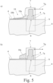
- a stripping element 18 is provided here and preferably for spreading the material 4 applied to the component edge 5, as shown in the Fig. 5 and 5
- the stripping element 18 forms a further limitation of the outlet opening 8.
- the stripping element 18 can be connected in one piece to the nozzle 7, or it can be detachably attached to the nozzle 7, so that it can also be exchanged for a different type of stripping element 18. This is shown in Fig. 4
- the shape and/or thickness of the applied seam can be influenced by different stripping elements 18. This is possible both by designing the shape of a stripping contour of the stripping element 18 and by designing the stripping element 18 itself.
- the stripping element 18 can be designed as a, in particular flexible, lip 18a, as shown in Fig. 5a This can have sliding contours 18b and/or bristles on its wiping edge.
- the wiping element 18 can be designed as a, in particular sponge-like, pad 18c, as shown in the Fig. 5b is shown.
- a sponge-like pad 18c preferably slides flatly on the component edge 5 or the viscous material 4 applied thereto.
- the stripping element 18 has sliding contours 18b which, when stripping, create channels in the seam made of viscous material 4, which run again before the viscous material 4 hardens. Different seam shapes can be produced using the different stripping elements 18.
- the end effector 2 can also be Fig. 1 shown have a cartridge holder 20 for receiving a cartridge 21 with the viscous material 4.
- the cartridge holder 20 receives a cartridge 21 with a cartridge nozzle 21a.
- the cartridge nozzle 21a opens here and preferably into the nozzle 7 of the application unit 3, as in the Fig. 3 shown.
- a controller 19 can be provided for controlling the end effector 2.
- the controller 19 of the end effector 3 is integrated into the controller of the manipulator 1.
- the manipulator 1 with the end effector 2 with the proposed application unit 3 is controlled during the process for applying the viscous material 4.
- the component is approached with the nozzle 7.
- the nozzle 7 is pre-tensioned here and preferably on the component edge 5, here in the exit direction of the viscous material 4.
- the sensors 9, 10 are pre-tensioned on the component 6.
- the first sensor 9 is moved transversely to the component edge 5 and thus pre-tensioned against the component 6, in the width direction of the exit opening 8.
- the second sensor 10 is pre-tensioned against the component 6 by activating the second pre-tensioning unit 17.
- the pneumatic spring element presses the second sensor 10 against the component 6.
- the viscous material 4 is applied by guiding the nozzle 7 along the component edge 5. If the component edge 5 changes its width B K , the width B A of the outlet opening 8 of the nozzle 7 is adjusted to the width B K of the component edge 5 by means of the buttons 9, 10.
Landscapes
- Coating Apparatus (AREA)
Description
- Die vorliegende Erfindung betrifft eine Applikationseinheit zum Auftragen von viskosem Material auf eine, insbesondere in der Breite variierende, Bauteilkante eines Bauteils. Ferner betrifft die Erfindung einen Endeffektor mit einer solchen Applikationseinheit sowie einen Manipulator mit einem solchen Endeffektor und/oder einer solchen Applikationseinheit.
- Aus dem Stand der Technik sind verschiedene Applikationseinheiten für viskose Materialien bekannt. Beispielsweise sind in der
EP 0 707 937 A1 , derUS 2016/0325307 A1 und derUS 2016/0271629 A1 Applikationseinheiten beschrieben. In derDE 10 2013 003 688 A1 ist eine Applikationseinheit mit einer Kombinationsdüse beschrieben, welche mittels einer Führungsrolle während des Auftragens des viskosen Materials in einer definierten Lage zu der Bauteilkante gehalten wird, auch wenn die Bauteilkante eine variierende Breite aufweist. Nachteilig an dieser Konstruktion ist jedoch, dass im Bereich des Auftrags des viskosen Materials Platz sowohl für die Düse als auch für die Führungsrolle benötigt wird, wodurch viskoses Material auf Bauteilkanten im Bereich von engen Ausschnitten mit der Applikationseinheit derDE 10 2013 003 688 A1 nicht auftragbar ist. Hinzu kommt, dass die Düse dieser Applikationseinheit einen kontinuierlichen Luftstrom zum Formen des viskosen Materials auf der Bauteilkante benötigt, was zu einem gesteigerten Energiebedarf und damit zu gesteigerten Betriebskosten führt. - Damit stellt sich die Aufgabe, eine im Betrieb kostengünstige Applikationseinheit bereitzustellen, welche das Auftragen von viskosem Material auf Bauteilkanten auch bei wenig Platz, insbesondere im Bereich enger Bauteilausschnitte, erlaubt.
- Diese Aufgabe wird durch die Applikationseinheit gemäß Anspruch 1 auf konstruktiv besonders einfache Art und Weise gelöst.
- Durch das Vorsehen einer Applikationseinheit mit einer Düse zum Auftragen des Materials auf die Bauteilkante mit einer in der Breite verstellbaren Austrittsöffnung ist ein variables Anpassen der Düsenbreite an die Breite der Bauteilkante und insbesondere auch auf eine variierende Breite einer Bauteilkante möglich.
- Weist die Applikationseinheit nun ferner einen ersten Taster mit einer Anlagefläche zur Anlage an das Bauteil und einen zweiten Taster mit einer Anlagefläche zur Anlage an das Bauteil auf, wobei der erste Taster und der zweite Taster mit einer Vorspannanordnung in entgegengesetzte Richtungen vorspannbar sind, ist eine besonders einfache, kompakte und kostengünstige Führung der Düse relativ zur Bauteilkante möglich. "In entgegengesetzte Richtungen vorspannbar" ist hier und vorzugsweise so zu verstehen, dass die Vektoren der Vorspannkraft der Taster zumindest je eine Komponente aufweisen, welche in entgegengesetzte Richtung orientiert ist.
- Um auch den Auftrag an die Breite der Bauteilkante anpassen zu können, ist vorschlagsgemäß ferner vorgesehen, dass die Breite der Austrittsöffnung abhängig vom Abstand der Anlagefläche des ersten Tasters zu der Anlagefläche des zweiten Tasters anpassbar ist. So kann eine im Bereich der Austrittsöffnung der Düse ganz besonders kompakte und konstruktiv einfache Applikationseinheit geschaffen werden, welche auch das Auftragen von viskosem Material auf Bauteilkanten im Bereich von engen Bauteilausschnitten ermöglicht.
- In einer Weiterbildung der Erfindung wird gemäß Anspruch 2 vorgeschlagen, dass einer der Taster, insbesondere der erste Taster, fest an der Düse angeordnet ist. Ferner bevorzugt ist, wenn einer der Taster, insbesondere der erste Taster, einstückig (integral) mit der Düse ausgebildet ist. Hierdurch wird eine ganz besonders kompakte Ausgestaltung der Düse im Bereich ihrer Austrittsöffnung ermöglicht.
- In der Weiterbildung gemäß Anspruch 3 wird vorgeschlagen, dass einer der Taster, insbesondere der zweite Taster, relativ zur Düse bewegbar, insbesondere linear verschiebbar, gelagert ist. Insbesondere hat sich eine Lagerung in oder an der Düse als vorteilhaft herausgestellt. Auf diese Weise ist eine Anpassung der Düsenbreite an die Breite der Bauteilkante auf einfache Art ermöglicht.
- Eine im Bereich der Austrittsöffnung besonders kompakte Düse lässt sich dadurch realisieren, dass die Düse mit dem ersten Taster und/oder dem zweiten Taster eine Düseneinheit bildet (Anspruch 4), wobei vorzugsweise der erste Taster und/oder der zweite Taster einen Abschnitt der Austrittsöffnung bereitstellt bzw. bereitstellen und durch eine Relativbewegung eines Tasters zu dem anderen Taster die Breite der Austrittsöffnung anpassbar ist. In diesem Fall können die Taster beim Auftragen des viskosen Materials beidseitig der Bauteilkante an dem Bauteil entlang gleiten und den Auftrag des viskosen Materials auf einfache Art und Weise auf die Bauteilkante begrenzen.
- Entsprechend wird gemäß der bevorzugten Ausbildung nach Anspruch 5 vorgeschlagen, dass die Applikationseinheit derart ausgebildet ist, dass die Breite der Austrittsöffnung, insbesondere kontinuierlich, an die Breite der Bauteilkante anpassbar ist bzw. angepasst wird. Hier und vorzugsweise entspricht die Breite der Austrittsöffnung im Wesentlichen, insbesondere genau, der Breite der Bauteilkante.
- Die Austrittsöffnung der Düse kann gemäß Anspruch 6 vorzugsweise durch einen der Taster, insbesondere den zweiten Taster, oder die Taster verschließbar sein. Vorzugsweise wird die Austrittsöffnung der Düse durch eine Relativbewegung eines der Taster, insbesondere des zweiten Tasters, zur Düse oder durch eine Relativbewegung der Taster zur Düse vor und/oder nach dem Auftragen des viskosen Materials verschlossen. Auf diese Weise kann ein ungewolltes Heraustropfen des viskosen Materials aus der Austrittsöffnung beim Verfahren der Applikationseinheit zu oder von der Bauteilkante vermieden werden.
- Es ist vorgesehen, dass die Applikationseinheit eine Aufnahmeeinheit zur Aufnahme der Düse und/oder der Düseneinheit aufweist. Die Düse und/oder die Düseneinheit ist an einer Schnittstelle von der Aufnahmeeinheit lösbar. Besonders bevorzugt ist die Düse bzw. ist die Düseneinheit werkzeuglos von der Aufnahmeeinheit lösbar. Hierdurch kann die Düse bzw. die Düseneinheit als Einwegteil ausgebildet werden. Eine aufwendige Reinigung der Düse nach dem Applizieren erübrigt sich. Sie kann einfach und kostengünstig ausgetauscht werden. Die Einsatzzeiten der Applikationseinheit können entsprechend gesteigert werden, da die Reinigung durch das Wegwerfen entfällt oder separat von der Applikationseinheit erfolgen kann.
- Die Vorspannanordnung weist mindestens eine Vorspanneinheit, insbesondere eine erste Vorspanneinheit, zum Vorspannen eines der Taster in eine erste Richtung auf. Vorzugsweise weist die Vorspannanordnung zusätzlich eine zweite Vorspanneinheit zum Vorspannen des anderen Tasters in eine entgegengesetzte Richtung auf.
- Gemäß Anspruch 11 kann die Düse zumindest teilweise, bevorzugt überwiegend, besonders bevorzugt vollständig, aus Kunststoff, insbesondere Polyethylen, sein und/oder, der Taster zumindest teilweise, bevorzugt überwiegend, besonders bevorzugt vollständig, aus Kunststoff, insbesondere Polyethylen, sein und/oder, die Düseneinheit zumindest teilweise, bevorzugt überwiegend, besonders bevorzugt vollständig, aus Kunststoff, insbesondere Polyethylen, sein.
- Weitere vorteilhafte Ausgestaltungen der Applikationseinheit finden sich in den weiteren Ansprüchen.
- Darüber hinaus wird die eingangs genannte Aufgabe bei einem Endeffektor durch die Merkmale des Anspruchs 14 gelöst. Es ergeben sich die gleichen Vorteile wie vorstehend mit der Applikationseinheit beschrieben.
- Bei einem Manipulator wird die eingangs beschriebene Aufgabe durch einen Manipulator mit den Merkmalen des Anspruchs 15 gelöst. Auch hier ergeben sich die gleichen Vorteile wie vorstehend in Zusammenhang mit der Applikationseinheit beschrieben.
- Schließlich wird die eingangs beschriebene Aufgabe verfahrensmäßig durch die Merkmale von Anspruch 16 gelöst. Auch hier ergeben sich die gleichen Vorteile wie vorstehend in Zusammenhang mit der Applikationseinheit beschrieben.
- Im Folgenden wird die Erfindung anhand einer lediglich ein Ausführungsbeispiel darstellenden Zeichnung näher erläutert. In der Zeichnung zeigt
- Fig. 1
- eine vorschlagsgemäße Applikationseinheit mit einem vorschlagsgemäßen Endeffektor an einem vorschlagsgemäßen Manipulator,
- Fig. 2
- a) die vorschlagsgemäße Applikationseinheit beim Auftragen des viskosen Materials auf eine Bauteilkante und b) die vorschlagsgemäße Applikationseinheit mit einer von der Aufnahmeeinheit gelösten Düseneinheit,
- Fig. 3
- die vorschlagsgemäße Applikationseinheit in einer Schnittdarstellung im Längsschnitt gemäß III in
Fig. 2 und - Fig. 4
- die Düse in einer Schnittdarstellung im Längsschnitt gemäß IV in
Fig. 2 in einer ersten Ausführung mit einem ersten Abstreifelement zum Abstreifen des viskosen Materials auf der Bauteilkante und - Fig. 5
- a) die Düse in einer Schnittdarstellung im Querschnitt gemäß V in
Fig. 2 in einer Ausführung mit einer Lippe als Abstreifelement und b) die Düse in einer Schnittdarstellung im Querschnitt gemäß V inFig. 2 in einer Ausführung mit einem schwammartigen Pad als Abstreifelement. - In der
Fig. 1 ist ein vorschlagsgemäßer Manipulator 1 mit einem vorschlagsgemäßen Endeffektor 2 und einer vorschlagsgemäßen Applikationseinheit 3 gezeigt. Der Manipulator 1 kann insbesondere ein Industrieroboter mit mindestens drei Achsen oder vier mindestens Achsen bzw. ein Portalroboter mit mindestens drei Achsen oder mindestens vier Achsen sein. Der inFig. 1 gezeigte Manipulator 1 weist sechs Achsen auf. - Die Applikationseinheit 3 dient dem Auftragen eines viskosen Materials 4 auf eine, insbesondere in der Breite BK und/oder Lage variierende, Bauteilkante 5 eines Bauteils 6. Eine solche Bauteilkante ist in der
Fig. 2a gezeigt. Die Bauteilkante 5 ist hier eine Stirnfläche des Bauteils 6, insbesondere eine Stirnfläche eines plattenförmigen Abschnitts des Bauteils 6. Bei der Breite BK der Bauteilkante 5 handelt es sich um die Breite quer zur Verlaufsrichtung VB der Bauteilkante 5. - Vorzugsweise ist das Bauteil 5 ein Strukturbauteil, insbesondere ein Kraftfahrzeugstrukturbauteil und/oder ein Flugzeugstrukturbauteil, beispielsweise ein Stringer. Bei dem Bauteil 5 kann es sich insbesondere auch um einen Zusammenbau aus verschiedenen Teilen 6a, 6b handeln, wie dies in der
Fig. 3 gezeigt ist. Insbesondere kann das Bauteil 5 ein Verbundbauteil, vorzugsweise ein Verbundbauteil aus kohlefaserverstärktem Kunststoff (CFK) und/oder ein Verbundbauteil aus glasfaserverstärktem Aluminium, sogenanntem Glare, sein. - Das viskose Material 4 kann insbesondere ein Klebstoff und/oder ein Dichtungsmaterial sein. Vorzugsweise ist das viskose Material ein Zweikomponenten-Epoxid. Dieses wird vorzugsweise vor dem Austritt aus der Austrittsöffnung 8 gemischt. Dabei kann es, wie dies im Ausführungsbeispiel der Fall ist, vor dem Eintritt in die Applikationseinheit 3 gemischt werden. Alternativ kann es jedoch auch in der Applikationseinheit, insbesondere in der Düse 7, oder beim Eintritt in die Applikationseinheit 3, insbesondre in die Düse 7, gemischt werden.
- Die Applikationseinheit 3 weist vorschlagsgemäß eine Düse 7 zum Auftragen des Materials auf die Bauteilkante 5 mit einer in der Breite BA verstellbaren Austrittsöffnung 8 auf.
- Die Austrittsöffnung 8 ist hier und vorzugsweise winkelig zur Längserstreckung der Düse 7 ausgebildet. Vorzugsweise ist die Austrittsöffnung 8 wie im Ausführungsbeispiel dargestellt in einer Richtung orthogonal zur Längserstreckung L der Düse 7 angeordnet. Hierdurch können Bauteilkanten 5 von engen Aussparungen auf einfache Art und Weise flexibel versiegelt werden. Grundsätzlich ist es gemäß eines alternativen Ausführungsbeispiels jedoch auch denkbar, dass die Austrittsöffnung 8 in Richtung der Längserstreckung L der Düse 7 weist.
- Die Applikationseinheit 3 weist ferner vorschlagsgemäß einen ersten Taster 9 mit einer Anlagefläche 9a zur Anlage an das Bauteil 6, insbesondere an eine an die Bauteilkante 5 angrenzende erste Seite des Bauteils 6, und einen zweiten Taster 10 mit einer Anlagefläche 10a zur Anlage an das Bauteil 6, insbesondere an eine an die Bauteilkante 5 angrenzende zweite, der ersten Seite gegenüberliegende Seite, auf.
- Der erste Taster 9 und der zweite Taster 10 sind mit einer Vorspannanordnung 11 in entgegengesetzte Richtungen auf das Bauteil 6 vorspannbar. Die Breite BA der Austrittsöffnung 8 kann nun abhängig vom Abstand der Anlagefläche 9a des ersten Tasters 9 und der Anlagefläche 10a des zweiten Tasters 10 angepasst werden. Hierdurch ist ein besonders einfaches energiesparendes Auftragen auf die Bauteilkante 5 möglich. Darüber hinaus wird hierdurch auch eine besonders kompakte Ausgestaltung der Düse 7 im Bereich der Austrittsöffnung 8 ermöglicht, wodurch auch auf die Bauteilkanten 5 von engen Ausschnitten das viskose Material 4 aufgetragen werden kann. Zudem wird eine konstruktiv einfache und damit kostengünstige Konstruktion ermöglicht.
- Unter "in entgegengesetzte Richtungen vorspannbar" ist hier und vorzugsweise zu verstehen, dass die Vektoren V1, V2 der Vorspannkraft der Taster 9, 10 zumindest je eine Komponente aufweisen, welche in entgegengesetzte Richtung orientiert ist. Vorzugsweise sind die Vektoren V1, V2 der Vorspannkraft parallel zur Breitenrichtung der Düse 7 angeordnet.
- Die Anlageflächen 9a, 10a der beiden Taster 9, 10 liegen hier wie in der
Fig. 2 gezeigt einander gegenüber. Entsprechend sind die beiden Taster 9, 10 hier und vorzugsweise auch aufeinander vorspannbar. - Wie in der Schnittdarstellung der
Fig. 3 gezeigt, kann einer der Taster 9 fest an der Düse 7 angeordnet sein. Hier ist der Taster 9 einstückig (integral) mit der Düse 7 ausgebildet. Er bildet einen Tastabschnitt der Düse 7 aus. Alternativ kann der Taster 9 auch eine Rolle aufweisen, welche ein Gleiten des Tasters 9 entlang des Bauteils 6 beim Auftragen des viskosen Materials 4 erleichtern kann. - Der zweite Taster 10 ist relativ zur Düse 7 bewegbar gelagert. Hier ist der zweite Taster 10 linear verschiebbar in der Düse 7 gelagert. Eine alternative bevorzugte Ausgestaltung sieht vor, dass der zweite Taster 10 an der Düse 7 bewegbar, insbesondere linear verschiebbar, gelagert ist.
- Hier ist der zweite Taster 10 als Schiebestein ausgebildet, welcher translatorisch bewegbar ist. Alternativ kann der Taster 10 jedoch auch eine Rolle aufweisen, welche ein Gleiten des Tasters 10 entlang des Bauteils 6 beim Auftragen des viskosen Materials 4 erleichtert.
- In einem alternativen Ausführungsbeispiel können beide Taster 9, 10 relativ zur Düse 7 bewegbar, insbesondere linear verschiebbar, gelagert sein. Vorzugsweise sind diese dann in oder an der Düse 7 gelagert und/oder beide so ausgebildet, wie zuvor für den zweiten Taster 10 beschrieben.
- Im Ausführungsbeispiel bildet die Düse 7 mit dem ersten Taster 9 und/oder dem zweiten Taster 10 eine Düseneinheit 12. Hier und vorzugsweise ist es so, dass der erste Taster 9 und der zweite Taster 10 je einen Abschnitt der Austrittsöffnung 8 bereitstellen. Die Breite BA der Austrittsöffnung 8 kann so durch eine Relativbewegung eines Tasters 9, 10 zu dem anderen Taster 9, 10 angepasst werden, wie dies in der
Fig. 3 in den Vergrößerungen gezeigt ist. - Hier weist die Düseneinheit 12 einen Aufnahmebereich 13 zur Aufnahme der Bauteilkante 5 des Bauteils 6 beim Auftragen des viskosen Materials 4 auf die Bauteilkante 5 auf. Dieser wird hier von dem ersten Taster 9 und dem zweiten Taster 10 beim Auftragen des viskosen Materials 4 auf die Bauteilkante 8 in Breitenrichtung der Austrittsöffnung 8 begrenzt.
- Die Applikationseinheit 3 ist hier derart ausgebildet, dass die Breite BA der Austrittsöffnung 8, insbesondere kontinuierlich, an die Breite BK der Bauteilkante 5 anpassbar ist bzw. während des Auftragens angepasst werden kann. Hier und vorzugsweise erfolgt das Anpassen passiv, also ohne die gezielte Ansteuerung eines Aktuators zum Einstellen der Änderung.
- Neben der Düseneinheit 12 weist die Applikationseinheit 3 eine Aufnahmeeinheit 13 zur Aufnahme der Düseneinheit 12 auf. Wie in der
Fig. 2b gezeigt, ist die Düseneinheit 12 an einer Schnittstelle 14 von der Aufnahmeeinheit 13 lösbar. Im Ausfiihrungsbeispiel kann die Düseneinheit 12 werkzeuglos von der Aufnahmeeinheit 13 gelöst werden. Die Schnittstelle 14 ist hier als Schnellverschluss ausgestaltet und kann durch das Bewegen einer Hülse 15, insbesondere entgegen einer Federvorspannung, einfach aus einer Arretierung an der Aufnahmeeinheit 13 entfernt werden. Es ist hier festzustellen, dass die Düse 7, wenn diese von der Aufnahmeeinheit 13 verriegelt aufgenommen ist, mit dieser fest verbunden ist. - Zum Erzeugen der Vorspannung weist die Vorspannanordnung 11 mindestens eine, insbesondere eine erste, Vorspanneinheit 16 zum Vorspannen eines der Taster 9 in eine erste Richtung Ri auf.
- Die erste Vorspanneinheit 16 ist hier an der Aufnahmeeinheit 13 angeordnet. Sie wirkt hier zwischen einem Befestigungsflansch 13a zur Befestigung der Applikationseinheit 3 an dem Manipulator 1 und der Düse 7. Im Ausführungsbeispiel weist sie ein Spiralfederelement 16a als Federelement auf. Alternativ kann die erste Vorspanneinheit 16 jedoch auch ein pneumatisches Federelement und/oder ein Blattfederelement aufweisen. Ferner kann die erste Vorspanneinheit 16 ein weiteres Federelement, insbesondere ein als Spiralfederelement 16b ausgebildetes Federelement aufweisen, welches gegen das Federelement 16a der ersten Vorspanneinheit 16 vorgespannt ist. Dieses Federelement 16b kann gleichzeitig die Hülse 15 in ihre Arretierstellung vorspannen.
- Erzeugt wird die Vorspannung des ersten Tasters 9 mittels der ersten Vorspanneinheit 16. Hierzu wird die Bauteilkante 5 mit der Düse 7 angefahren und anschließend der erste Taster 9 gegen das Bauteil 6 vorgespannt, indem durch eine Manipulatorbewegung in Richtung des zweiten Tasters 10 die erste Vorspanneinheit 16 gespannt und der erste Taster 9 auf das Bauteil 5 vorgespannt wird.
- Im Ausführungsbeispiel weist die Vorspannanordnung 16 ferner eine zweite Vorspanneinheit 17 zum Vorspannen des anderen Tasters 10 in die entgegengesetzte Richtung R2 auf. Zur Definition der entgegengesetzten Richtungen darf auf die obenstehenden Ausführungen verwiesen werden. Hier und vorzugsweise ist es jedoch so, dass die Richtungen parallel zur Breitenrichtung der Austrittsöffnung 8 angeordnet sind.
- Auch die zweite Vorspanneinheit 17 ist hier und vorzugsweise an der Aufnahmeeinheit 13 angeordnet. Sie wirkt hier zwischen dem Befestigungsflansch 13a und dem zweiten Taster 10. Alternativ kann die zweite Vorspanneinheit 17 jedoch auch an der Düse 7 angeordnet sein. Sie weist zum Erzeugen der Vorspannkraft ebenfalls ein Federelement auf. Dies ist im Ausführungsbeispiel ein pneumatisches Federelement, hier in Form eines Pneumatikzylinders. Mittels des Pneumatikzylinders kann die Vorspannung des zweiten Tasters 10 aktiviert oder deaktiviert werden. Durch die Aktivierung lässt sich die Bauteilkante 5 wie in der
Fig. 3 gezeigt zwischen den beiden Tastern 9, 10 klemmen. - Die Vorspanneinheiten 16, 17 dienen sowohl zum Ausgleich von Toleranzen des Bauteils 6 entlang der Bauteilkante 5, also der variierenden Lage der Bauteilkante, wie auch zum Ausgleich von Änderungen der Breite BK der Bauteilkante 5.
- Die Düse 7 und die Taster 9, 10 sind hier und vorzugsweise aus Kunststoff, insbesondere Polyethylen. Eine Ausgestaltung der Düseneinheit 12 aus Kunststoff ermöglicht eine besonders kostengünstige Herstellung derselben. Dies bietet, insbesondere wenn die Düseneinheit 12 als Austausch- und/oder Einwegteil ausgebildet ist, erhebliche Kostenvorteile. Dies ist besonders vorteilhaft, wenn die Düse 7 als Einwegteil ausgebildet ist, da dies eine kostengünstige Herstellung derselben ermöglicht.
- Wie in der
Fig. 5 gezeigt, kann die Düse 7 ein der Austrittsöffnung 8 beim Auftragen des viskosen Materials 4 vorrauslaufendes Abstützelement 7a, hier und vorzugsweise als eine vordere Begrenzung der Austrittsöffnung 8, aufweisen. Über dieses kann die Düse 7, insbesondere von dem Manipulator 1, in einer Richtung orthogonal zur Fläche der Bauteilkante 5 auf diese vorgespannt werden. - Der Austrittsöffnung 18 nachlaufend ist hier und vorzugsweise ein Abstreifelement 18 zum Verstreichen des auf die Bauteilkante 5 aufgetragenen Materials 4 vorgesehen, wie dies in den
Fig. 5 und 5 gezeigt ist. Das Abstreifelement 18 bildet hier eine weitere Begrenzung der Austrittsöffnung 8. Das Abstreifelement 18 kann einstückig mit der Düse 7 verbunden sein, oder es kann lösbar an der Düse 7 befestigt sein, so dass dieses auch gegen ein andersartiges Abstreifelement 18 ausgetauscht werden kann. Dies ist inFig. 4 dargestellt. Durch unterschiedliche Abstreifelemente 18 kann die Form und/oder Dicke der aufgetragenen Naht beeinflusst werden. Dies ist sowohl durch die Ausgestaltung der Form einer Abstreifkontur des Abstreifelements 18 als auch durch die Ausgestaltung des Abstreifelements 18 selbst möglich. - Das Abstreifelement 18 kann als, insbesondere flexible, Lippe 18a ausgebildet sein, wie dies in
Fig. 5a gezeigt ist. Diese kann an ihrer Streichkante Gleitkonturen 18b und/oder Borsten aufweisen. Alternativ kann das Abstreifelement 18 als, insbesondere schwammartiges, Pad 18c ausgebildet sein, wie dies in derFig. 5b gezeigt ist. Ein schwammartiges Pad 18c gleitet beim Auftragen des viskosen Materials 4 vorzugsweise flächig auf der Bauteilkante 5 bzw. dem darauf aufgetragenen viskosen Material 4. - In einer besonders bevorzugten Ausführung weist das Abstreifelement 18 Gleitkonturen 18b auf, welche beim Abstreifen Gassen in der Naht aus viskosem Material 4 erzeugen, welche vor dem Aushärten des viskosen Materials 4 wieder verlaufen. Mit den unterschiedlichen Abstreifelementen 18 lassen sich unterschiedliche Nahtformen herstellen.
- Der Endeffektor 2 kann ferner wie in
Fig. 1 gezeigt eine Kartuschenaufnahme 20 zur Aufnahme einer Kartusche 21 mit dem viskosen Material 4 aufweisen. Vorzugsweise nimmt die Kartuschenaufnahme 20 eine Kartusche 21 mit einer Kartuschendüse 21a auf. Die Kartuschendüse 21a mündet hier und vorzugsweise in der Düse 7 der Applikationseinheit 3, wie in derFig. 3 gezeigt. - Zudem kann eine Steuerung 19 zur Steuerung des Endeffektors 2 vorgesehen sein. Vorzugsweise ist die Steuerung 19 des Endeffektors 3 in die Steuerung des Manipulators 1 integriert. Mittels der Steuerung 19 wird der Manipulator 1 mit dem Endeffektor 2 mit der vorschlagsgemäßen Applikationseinheit 3 während des Verfahrens zum Auftragen des viskosen Materials 4 gesteuert.
- Zum Auftragen des viskosen Materials 4 auf die Bauteilkante 5 wird diese mit der Düse 7 angefahren. Dabei wird die Düse 7 hier und vorzugsweise auf die Bauteilkante 5 vorgespannt, hier in Austrittsrichtung des viskosen Materials 4. Dann werden die Taster 9, 10 auf das Bauteil 6 vorgespannt. Hier wird der erste Taster 9 quer zur Bauteilkante 5 bewegt und so gegen das Bauteil 6, in Breitenrichtung der Austrittsöffnung 8 vorgespannt. Der zweite Taster 10 wird durch Aktivieren der zweiten Vorspanneinheit 17 gegen das Bauteil 6 vorgespannt. Das pneumatische Federelement drückt den zweiten Taster 10 gegen das Bauteil 6. Das viskose Material 4 wird durch Führen der Düse 7 entlang der Bauteilkante 5 aufgetragen. Ändert die Bauteilkante 5 ihre Breite BK, wird die Breite BA der Austrittsöffnung 8 der Düse 7 mittels der Taster 9, 10 an die Breite BK der Bauteilkante 5 angepasst.
Claims (16)
- Applikationseinheit zum Auftragen eines viskosen Materials (4) auf eine, insbesondere in der Breite (BK) und/oder Lage variierende, Bauteilkante (5) eines Bauteils (6),wobei die Applikationseinheit (3) eine Düse (7) zum Auftragen des viskosen Materials (4) auf die Bauteilkante (5) mit einer in der Breite (BA) verstellbaren Austrittsöffnung (8) aufweist, wobei die Applikationseinheit (3) eine Aufnahmeeinheit (13) zur Aufnahme der Düse (7) und/oder einer Düseneinheit (12) aufweist,wobei die Applikationseinheit (3) einen ersten Taster (9) mit einer Anlagefläche (9a) zur Anlage an das Bauteil (6) und einen zweiten Taster (10) mit einer Anlagefläche (10a) zu Anlage an das Bauteil (6) aufweist, wobei der erste Taster (9) und der zweite Taster (10) mit einer Vorspannanordnung (11) in entgegengesetzte Richtungen (R1,R2) vorspannbar sind und wobei die Breite (BA) der Austrittsöffnung (8) abhängig vom Abstand der Anlagefläche (9a) des ersten Tasters (9) zu der Anlagefläche (10a) des zweiten Tasters (10) anpassbar ist, wobei die Vorspannanordnung (11) mindestens eine, insbesondere eine erste, Vorspanneinheit (16) zum Vorspannen eines der Taster (9, 10) in eine erste Richtung (R1) aufweist,dadurch gekennzeichnet,dass die Düse (7) und/oder die Düseneinheit (12) an einer Schnittstelle (14) von der Aufnahmeeinheit (13) lösbar ist und dass die erste Vorspanneinheit (16) Bestandteil der Aufnahmeeinheit (13) ist.
- Applikationseinheit nach Anspruch 1, dadurch gekennzeichnet, dass einer der Taster (9, 10), insbesondere der erste Taster (9), fest an der Düse (7) angeordnet ist, vorzugsweise, dass einer der Taster (9, 10), insbesondere der erste Taster (10), einstückig mit der Düse (7) ausgebildet ist.
- Applikationseinheit nach Anspruch 1 oder 2, dadurch gekennzeichnet, dass einer der Taster (9, 10), insbesondere der zweite Taster (10), relativ zur Düse (7) bewegbar, insbesondere linear verschiebbar, gelagert ist, vorzugsweise, dass einer der Taster (9, 10), insbesondere der zweite Taster (10), in oder an der Düse (7) relativ zu dieser bewegbar, insbesondere linear verschiebbar, gelagert ist.
- Applikationseinheit nach einem der vorhergehenden Ansprüche, dadurch gekennzeichnet, dass die Düse (7) mit dem ersten Taster (9) und/oder dem zweiten Taster (10) die Düseneinheit (12) bildet, vorzugsweise, dass der erste Taster (9) und/oder der zweite Taster (10) einen Abschnitt der Austrittsöffnung (8) bereitstellt beziehungsweise bereitstellen und durch eine Relativbewegung eines Tasters (9, 10) zu dem anderen Taster (9, 10) die Breite (BA) der Austrittsöffnung (8) anpassbar ist.
- Applikationseinheit nach einem der vorhergehenden Ansprüche, dadurch gekennzeichnet, dass die Applikationseinheit (3) derart ausgebildet ist, dass die Breite (BA) der Austrittsöffnung (8), insbesondere kontinuierlich, an die Breite (BK) der Bauteilkante (5) anpassbar ist beziehungsweise angepasst wird.
- Applikationseinheit nach einem der vorhergehenden Ansprüche, dadurch gekennzeichnet, dass die Austrittsöffnung der Düse (7) durch einen der Taster (9, 10), insbesondere den zweiten Taster (10), oder die Taster (9, 10) verschließbar ist, vorzugsweise, dass die Austrittsöffnung der Düse (7) durch eine Relativbewegung eines der Taster (9, 10), insbesondere des zweiten Tasters (10), oder der Taster (9, 10) zur Düse (7) vor und/oder nach dem Auftragen des viskosen Materials (4) verschlossen wird.
- Applikationseinheit nach einem der vorhergehenden Ansprüche, dadurch gekennzeichnet, dass die Düse (7) und/oder die Düseneinheit (12) werkzeuglos von der Aufnahmeeinheit (13) lösbar ist.
- Applikationseinheit nach einem der vorhergehenden Ansprüche, dadurch gekennzeichnet, dass die Vorspannanordnung (11) eine zweite Vorspanneinheit (17) zum Vorspannen des anderen Tasters (9, 10) in eine entgegengesetzte Richtung (R2) aufweist.
- Applikationseinheit nach einem der vorhergehenden Ansprüche, dadurch gekennzeichnet, dass die zweite Vorspanneinheit (17) Bestandteil der Aufnahmeeinheit (13) ist und/oder an der Düse (7) angeordnet ist.
- Applikationseinheit nach einem der vorhergehenden Ansprüche, dadurch gekennzeichnet, dass die erste Vorspanneinheit (16) zum Erzeugen der Vorspannkraft ein Federelement (16a), insbesondere ein pneumatisches Federelement und/oder ein Spiralfederelement und/oder ein Blattfederelement, aufweist,
und/oder,
dass die zweite Vorspanneinheit (17) zum Erzeugen der Vorspannkraft ein Federelement, insbesondere ein pneumatisches Federelement und/oder ein Spiralfederelement und/oder ein Blattfederelement aufweist. - Applikationseinheit nach einem der vorhergehenden Ansprüche, dadurch gekennzeichnet, dass die Düse (7) zumindest teilweise, bevorzugt überwiegend, besonders bevorzugt vollständig, aus Kunststoff, insbesondere Polyethylen, ist und/oder,dass der zweite Taster (10) zumindest teilweise, bevorzugt überwiegend, besonders bevorzugt vollständig, aus Kunststoff, insbesondere Polyethylen, ist und/oder,dass die Düseneinheit (12) zumindest teilweise, bevorzugt überwiegend, besonders bevorzugt vollständig, aus Kunststoff, insbesondere Polyethylen, ist.
- Applikationseinheit nach einem der vorhergehenden Ansprüche, dadurch gekennzeichnet, dass die Düse (7) ein, insbesondere mit der Düse (7) einstückig verbundenes, Abstreifelement (18) zum Verstreichen des auf die Bauteilkante (5) aufgetragenen Materials (4) aufweist.
- Applikationseinheit nach einem der vorhergehenden Ansprüche, dadurch gekennzeichnet, dass die Austrittsöffnung (8) winkelig zur Längserstreckung (L) der Düse (7) weist, vorzugsweise, dass die Austrittsöffnung (8) in eine Richtung orthogonal zur Längserstreckung (L) der Düse (7) weist.
- Endeffektor mit einer Applikationseinheit (3) nach einem der vorhergehenden Ansprüche.
- Manipulator mit einem Endeffektor (2) und/oder einer Applikationseinheit (3) nach einem der vorhergehenden Ansprüche.
- Verfahren zum Auftragen eines viskosen Materials (4) auf eine, insbesondere in der Breite (BK) und/oder Lage variierende, Bauteilkante (5) eines Bauteils (6) mit einer Applikationseinheit (3) nach einem der Ansprüche 1 bis 12, wobei während des Auftragens des viskosen Materials (4) mittels einer Düse (7) ein Taster (9, 10) auf das Bauteil (6) vorgespannt ist und mittels des Tasters (9, 10) die Breite (BA) einer Austrittsöffnung (8) der Düse (7) an die Breite (BK) der Bauteilkante (5) angepasst wird.
Applications Claiming Priority (2)
| Application Number | Priority Date | Filing Date | Title |
|---|---|---|---|
| DE102016123416.8A DE102016123416A1 (de) | 2016-12-05 | 2016-12-05 | Applikationseinheit |
| PCT/EP2017/077059 WO2018103941A1 (de) | 2016-12-05 | 2017-10-24 | Applikationseinheit |
Publications (2)
| Publication Number | Publication Date |
|---|---|
| EP3548189A1 EP3548189A1 (de) | 2019-10-09 |
| EP3548189B1 true EP3548189B1 (de) | 2025-01-08 |
Family
ID=60164702
Family Applications (1)
| Application Number | Title | Priority Date | Filing Date |
|---|---|---|---|
| EP17788215.6A Active EP3548189B1 (de) | 2016-12-05 | 2017-10-24 | Applikationseinheit |
Country Status (6)
| Country | Link |
|---|---|
| US (1) | US11179743B2 (de) |
| EP (1) | EP3548189B1 (de) |
| CN (1) | CN110191763B (de) |
| DE (1) | DE102016123416A1 (de) |
| RU (1) | RU2758420C2 (de) |
| WO (1) | WO2018103941A1 (de) |
Families Citing this family (5)
| Publication number | Priority date | Publication date | Assignee | Title |
|---|---|---|---|---|
| DE102016123416A1 (de) | 2016-12-05 | 2018-06-07 | Ba Assembly & Turnkey Systems Gmbh | Applikationseinheit |
| CN109201412A (zh) * | 2018-09-12 | 2019-01-15 | 珠海格力智能装备有限公司 | 涂胶设备 |
| CN111495705A (zh) * | 2020-04-30 | 2020-08-07 | 北京数字博文科技发展有限公司 | 玻璃直角边背胶工具 |
| CN111545422A (zh) * | 2020-04-30 | 2020-08-18 | 北京数字博文科技发展有限公司 | 玻璃斜边背胶工具 |
| DE102023110217A1 (de) | 2023-04-21 | 2024-10-24 | Homag Gmbh | Vorrichtung zum selektiven Auftragen von Haftmitteln, Verfahren zum Beschichten von Werkstücken, beschichtetes Werkstück und Verwendung davon |
Family Cites Families (23)
| Publication number | Priority date | Publication date | Assignee | Title |
|---|---|---|---|---|
| FR2725657B1 (fr) | 1994-10-17 | 1997-01-10 | Saint Gobain Vitrage | Dispositif pour l'extrusion d'un cordon profile en polymere sur un objet en forme de plaque |
| JP3793942B2 (ja) * | 2000-05-09 | 2006-07-05 | 日立建機株式会社 | 自動塗装装置 |
| JP4276860B2 (ja) * | 2003-02-21 | 2009-06-10 | 本田技研工業株式会社 | 保護層形成材の塗布装置 |
| FR2877239B1 (fr) * | 2004-11-03 | 2007-02-23 | Airbus France Sas | Dispositif de fourniture de materiau pateux |
| CN200948451Y (zh) * | 2006-05-19 | 2007-09-19 | 姜正一 | 管内面涂覆装置 |
| US20080138532A1 (en) * | 2006-12-12 | 2008-06-12 | Ford Global Technologies, Llc | Method for decorating a plastic component with a coating |
| CN201067732Y (zh) * | 2007-07-16 | 2008-06-04 | 泉州新日成热熔胶设备有限公司 | 具有改进支承机构的狭缝式涂布装置 |
| RU75964U1 (ru) * | 2008-03-06 | 2008-09-10 | Сергей Владимирович Толмачев | Устройство для подачи вязких материалов (два варианта) |
| DE202010013054U1 (de) * | 2010-12-03 | 2012-03-05 | Baumer Hhs Gmbh | Vorrichtung zum Auftragen von viskosen Medien |
| CN202725395U (zh) * | 2012-07-30 | 2013-02-13 | 奉化市必达机械制造有限公司 | 卡钳式快速换色喷枪 |
| DE102013003688A1 (de) | 2012-10-26 | 2014-04-30 | Fraunhofer-Gesellschaft zur Förderung der angewandten Forschung e.V. | Kombinationsdüse sowie Vorrichtung für den Auftrag eines viskosen Materials auf eine Bauteilkante |
| FR3012863B1 (fr) * | 2013-11-04 | 2017-04-07 | Sames Tech | Dispositif d'alimentation d'un projecteur en produit de revetement liquide |
| DE102014110375A1 (de) * | 2014-07-23 | 2016-01-28 | Fraunhofer-Gesellschaft zur Förderung der angewandten Forschung e.V. | Verfahren und Vorrichtung zum Erzeugen eines Auftrags eines pastösen und/oder flüssigen Mediums |
| KR101439078B1 (ko) * | 2014-07-31 | 2014-09-05 | 이윤철 | 도장용 더블 핀서 지그 장치 |
| CN204247455U (zh) * | 2014-11-16 | 2015-04-08 | 重庆渝西园林集团有限公司 | 树木涂白夹持机构 |
| US9884329B2 (en) * | 2015-03-19 | 2018-02-06 | The Boeing Company | Adhesive applicator having reversibly extensible first and second edges |
| US10065206B2 (en) * | 2015-05-04 | 2018-09-04 | The Boeing Company | Systems, methods, and apparatuses for applying viscous fluids to components |
| CN205096006U (zh) * | 2015-09-21 | 2016-03-23 | 重庆祥图科技有限公司 | 一种摩托车零件喷涂支架装置 |
| CN105327835B (zh) * | 2015-12-07 | 2017-12-01 | 常州高凯精密机械有限公司 | 一种压电串联式柱塞喷射点胶装置 |
| CN205436201U (zh) * | 2015-12-29 | 2016-08-10 | 浙江双正机床有限公司 | 一种阀帽与阀体之间的自动打胶预紧装置 |
| CN205342394U (zh) * | 2016-01-15 | 2016-06-29 | 宁波新邦工具有限公司 | 一种快速接头的螺帽涂胶预紧装置 |
| DE202016102348U1 (de) * | 2016-05-03 | 2016-05-20 | Fft Produktionssysteme Gmbh & Co. Kg | Kantenversiegelungsvorrichtung |
| DE102016123416A1 (de) | 2016-12-05 | 2018-06-07 | Ba Assembly & Turnkey Systems Gmbh | Applikationseinheit |
-
2016
- 2016-12-05 DE DE102016123416.8A patent/DE102016123416A1/de active Pending
-
2017
- 2017-10-24 EP EP17788215.6A patent/EP3548189B1/de active Active
- 2017-10-24 RU RU2019116744A patent/RU2758420C2/ru active
- 2017-10-24 CN CN201780075357.8A patent/CN110191763B/zh active Active
- 2017-10-24 WO PCT/EP2017/077059 patent/WO2018103941A1/de not_active Ceased
- 2017-10-24 US US16/466,710 patent/US11179743B2/en active Active
Also Published As
| Publication number | Publication date |
|---|---|
| RU2019116744A (ru) | 2021-01-11 |
| DE102016123416A1 (de) | 2018-06-07 |
| WO2018103941A1 (de) | 2018-06-14 |
| RU2019116744A3 (de) | 2021-02-10 |
| US20190299239A1 (en) | 2019-10-03 |
| CN110191763A (zh) | 2019-08-30 |
| RU2758420C2 (ru) | 2021-10-28 |
| CN110191763B (zh) | 2022-04-19 |
| EP3548189A1 (de) | 2019-10-09 |
| US11179743B2 (en) | 2021-11-23 |
Similar Documents
| Publication | Publication Date | Title |
|---|---|---|
| EP3548189B1 (de) | Applikationseinheit | |
| DE19535930C1 (de) | Vorrichtung zur veränderlichen Begrenzung eines flachen Fließkanals und Verfahren zum Austragen einer Massebahn mit veränderlicher Geometrie | |
| EP3386643B1 (de) | Verstreicheinheit | |
| DE29713448U1 (de) | Vorrichtung zur Ultraschallbearbeitung von Werkstücken | |
| DE3905728A1 (de) | Verfahren zum herstellen von z. b. angesenkten bohrungen mit kontrollierter tiefe und vorrichtung zur durchfuehrung dieses verfahrens | |
| EP2578347A2 (de) | Fügevorrichtung zum Verbinden von Strukturbauteilen eines Luftfahrzeuges | |
| EP3178627B1 (de) | Extrusionsvorrichtung und verfahren zum auffüllen einer nut mit einer füllmasse | |
| DE2618846B2 (de) | Biegemaschine zum Herstellen von Formteilen aus Metalldraht oder -band | |
| DE4239344A1 (en) | Robotic machining of workpieces using scraping process - involves manipulating workpiece so that features to be machined are drawn past scraper blade under controlled pressure | |
| WO2018010997A1 (de) | Applikator zur applikation eines dickstoffs, austauschteil dafür und entsprechendes betriebsverfahren | |
| DE102009000901B4 (de) | Dreistufige Ventilschaltanordnung | |
| DE102011112042A1 (de) | Rührreibschweißverfahren zur Verbindung von plattenförmigen Werkstücken sowie Vorrichtung hierfür | |
| EP0566951B1 (de) | Mischkopf zum Vermischen von mindestens zwei Kunststoff bildenden, fliessfähigen Reaktionskomponenten | |
| DE202015003445U1 (de) | Werkzeugaggregat | |
| DE102008047782A1 (de) | Vorrichtung zum Rundkneten von Werkstücken | |
| DE3808763C2 (de) | ||
| EP3519105B1 (de) | Verstreicheinheit | |
| EP3551401B1 (de) | Verfahren zum einbringen eines applikationsmediums in einen schwächungsspalt einer abdeckung sowie bevorzugte applikationsvorrichtung | |
| EP3178599B1 (de) | Ständermaschine | |
| DE102017123913A1 (de) | Vorrichtung zum Auftragen eines viskosen Materials | |
| EP2922639B1 (de) | Befüllvorrichtung mit einstellbarem auftragswinkel und verfahren zum befüllen eines bauteils | |
| DE19816824A1 (de) | Vorrichtung und Verfahren zum Materialauftragen | |
| DE102015225518B4 (de) | Betätigungsvorrichtung sowie Fahrzeug mit einer derartigen Betätigungsvorrichtung | |
| EP2186967A2 (de) | Anbauvorrichtung für eine Handmaschine | |
| DE102015110738A1 (de) | Mehrfachwirkende mechanische Presse und Verfahren zur Einstellung eines Phasenversatzes mittels einer derartigen Vorrichtung |
Legal Events
| Date | Code | Title | Description |
|---|---|---|---|
| STAA | Information on the status of an ep patent application or granted ep patent |
Free format text: STATUS: UNKNOWN |
|
| STAA | Information on the status of an ep patent application or granted ep patent |
Free format text: STATUS: THE INTERNATIONAL PUBLICATION HAS BEEN MADE |
|
| PUAI | Public reference made under article 153(3) epc to a published international application that has entered the european phase |
Free format text: ORIGINAL CODE: 0009012 |
|
| STAA | Information on the status of an ep patent application or granted ep patent |
Free format text: STATUS: REQUEST FOR EXAMINATION WAS MADE |
|
| 17P | Request for examination filed |
Effective date: 20190412 |
|
| AK | Designated contracting states |
Kind code of ref document: A1 Designated state(s): AL AT BE BG CH CY CZ DE DK EE ES FI FR GB GR HR HU IE IS IT LI LT LU LV MC MK MT NL NO PL PT RO RS SE SI SK SM TR |
|
| AX | Request for extension of the european patent |
Extension state: BA ME |
|
| DAV | Request for validation of the european patent (deleted) | ||
| DAX | Request for extension of the european patent (deleted) | ||
| STAA | Information on the status of an ep patent application or granted ep patent |
Free format text: STATUS: EXAMINATION IS IN PROGRESS |
|
| 17Q | First examination report despatched |
Effective date: 20201019 |
|
| GRAP | Despatch of communication of intention to grant a patent |
Free format text: ORIGINAL CODE: EPIDOSNIGR1 |
|
| STAA | Information on the status of an ep patent application or granted ep patent |
Free format text: STATUS: GRANT OF PATENT IS INTENDED |
|
| INTG | Intention to grant announced |
Effective date: 20240920 |
|
| GRAS | Grant fee paid |
Free format text: ORIGINAL CODE: EPIDOSNIGR3 |
|
| GRAA | (expected) grant |
Free format text: ORIGINAL CODE: 0009210 |
|
| STAA | Information on the status of an ep patent application or granted ep patent |
Free format text: STATUS: THE PATENT HAS BEEN GRANTED |
|
| AK | Designated contracting states |
Kind code of ref document: B1 Designated state(s): AL AT BE BG CH CY CZ DE DK EE ES FI FR GB GR HR HU IE IS IT LI LT LU LV MC MK MT NL NO PL PT RO RS SE SI SK SM TR |
|
| REG | Reference to a national code |
Ref country code: GB Ref legal event code: FG4D Free format text: NOT ENGLISH |
|
| REG | Reference to a national code |
Ref country code: CH Ref legal event code: EP |
|
| REG | Reference to a national code |
Ref country code: DE Ref legal event code: R096 Ref document number: 502017016649 Country of ref document: DE |
|
| REG | Reference to a national code |
Ref country code: IE Ref legal event code: FG4D Free format text: LANGUAGE OF EP DOCUMENT: GERMAN |
|
| REG | Reference to a national code |
Ref country code: LT Ref legal event code: MG9D |
|
| REG | Reference to a national code |
Ref country code: NL Ref legal event code: MP Effective date: 20250108 |
|
| PG25 | Lapsed in a contracting state [announced via postgrant information from national office to epo] |
Ref country code: NL Free format text: LAPSE BECAUSE OF FAILURE TO SUBMIT A TRANSLATION OF THE DESCRIPTION OR TO PAY THE FEE WITHIN THE PRESCRIBED TIME-LIMIT Effective date: 20250108 |
|
| PG25 | Lapsed in a contracting state [announced via postgrant information from national office to epo] |
Ref country code: RS Free format text: LAPSE BECAUSE OF FAILURE TO SUBMIT A TRANSLATION OF THE DESCRIPTION OR TO PAY THE FEE WITHIN THE PRESCRIBED TIME-LIMIT Effective date: 20250408 |
|
| PG25 | Lapsed in a contracting state [announced via postgrant information from national office to epo] |
Ref country code: FI Free format text: LAPSE BECAUSE OF FAILURE TO SUBMIT A TRANSLATION OF THE DESCRIPTION OR TO PAY THE FEE WITHIN THE PRESCRIBED TIME-LIMIT Effective date: 20250108 |
|
| PG25 | Lapsed in a contracting state [announced via postgrant information from national office to epo] |
Ref country code: PL Free format text: LAPSE BECAUSE OF FAILURE TO SUBMIT A TRANSLATION OF THE DESCRIPTION OR TO PAY THE FEE WITHIN THE PRESCRIBED TIME-LIMIT Effective date: 20250108 |
|
| PG25 | Lapsed in a contracting state [announced via postgrant information from national office to epo] |
Ref country code: ES Free format text: LAPSE BECAUSE OF FAILURE TO SUBMIT A TRANSLATION OF THE DESCRIPTION OR TO PAY THE FEE WITHIN THE PRESCRIBED TIME-LIMIT Effective date: 20250108 |
|
| PG25 | Lapsed in a contracting state [announced via postgrant information from national office to epo] |
Ref country code: IS Free format text: LAPSE BECAUSE OF FAILURE TO SUBMIT A TRANSLATION OF THE DESCRIPTION OR TO PAY THE FEE WITHIN THE PRESCRIBED TIME-LIMIT Effective date: 20250508 Ref country code: NO Free format text: LAPSE BECAUSE OF FAILURE TO SUBMIT A TRANSLATION OF THE DESCRIPTION OR TO PAY THE FEE WITHIN THE PRESCRIBED TIME-LIMIT Effective date: 20250408 |
|
| PG25 | Lapsed in a contracting state [announced via postgrant information from national office to epo] |
Ref country code: HR Free format text: LAPSE BECAUSE OF FAILURE TO SUBMIT A TRANSLATION OF THE DESCRIPTION OR TO PAY THE FEE WITHIN THE PRESCRIBED TIME-LIMIT Effective date: 20250108 |
|
| PG25 | Lapsed in a contracting state [announced via postgrant information from national office to epo] |
Ref country code: LV Free format text: LAPSE BECAUSE OF FAILURE TO SUBMIT A TRANSLATION OF THE DESCRIPTION OR TO PAY THE FEE WITHIN THE PRESCRIBED TIME-LIMIT Effective date: 20250108 Ref country code: PT Free format text: LAPSE BECAUSE OF FAILURE TO SUBMIT A TRANSLATION OF THE DESCRIPTION OR TO PAY THE FEE WITHIN THE PRESCRIBED TIME-LIMIT Effective date: 20250508 |
|
| PG25 | Lapsed in a contracting state [announced via postgrant information from national office to epo] |
Ref country code: GR Free format text: LAPSE BECAUSE OF FAILURE TO SUBMIT A TRANSLATION OF THE DESCRIPTION OR TO PAY THE FEE WITHIN THE PRESCRIBED TIME-LIMIT Effective date: 20250409 Ref country code: BG Free format text: LAPSE BECAUSE OF FAILURE TO SUBMIT A TRANSLATION OF THE DESCRIPTION OR TO PAY THE FEE WITHIN THE PRESCRIBED TIME-LIMIT Effective date: 20250108 |
|
| PG25 | Lapsed in a contracting state [announced via postgrant information from national office to epo] |
Ref country code: SE Free format text: LAPSE BECAUSE OF FAILURE TO SUBMIT A TRANSLATION OF THE DESCRIPTION OR TO PAY THE FEE WITHIN THE PRESCRIBED TIME-LIMIT Effective date: 20250108 |
|
| PG25 | Lapsed in a contracting state [announced via postgrant information from national office to epo] |
Ref country code: SM Free format text: LAPSE BECAUSE OF FAILURE TO SUBMIT A TRANSLATION OF THE DESCRIPTION OR TO PAY THE FEE WITHIN THE PRESCRIBED TIME-LIMIT Effective date: 20250108 |
|
| REG | Reference to a national code |
Ref country code: DE Ref legal event code: R097 Ref document number: 502017016649 Country of ref document: DE |
|
| PG25 | Lapsed in a contracting state [announced via postgrant information from national office to epo] |
Ref country code: DK Free format text: LAPSE BECAUSE OF FAILURE TO SUBMIT A TRANSLATION OF THE DESCRIPTION OR TO PAY THE FEE WITHIN THE PRESCRIBED TIME-LIMIT Effective date: 20250108 |
|
| PG25 | Lapsed in a contracting state [announced via postgrant information from national office to epo] |
Ref country code: EE Free format text: LAPSE BECAUSE OF FAILURE TO SUBMIT A TRANSLATION OF THE DESCRIPTION OR TO PAY THE FEE WITHIN THE PRESCRIBED TIME-LIMIT Effective date: 20250108 Ref country code: CZ Free format text: LAPSE BECAUSE OF FAILURE TO SUBMIT A TRANSLATION OF THE DESCRIPTION OR TO PAY THE FEE WITHIN THE PRESCRIBED TIME-LIMIT Effective date: 20250108 |
|
| PG25 | Lapsed in a contracting state [announced via postgrant information from national office to epo] |
Ref country code: RO Free format text: LAPSE BECAUSE OF FAILURE TO SUBMIT A TRANSLATION OF THE DESCRIPTION OR TO PAY THE FEE WITHIN THE PRESCRIBED TIME-LIMIT Effective date: 20250108 |
|
| PG25 | Lapsed in a contracting state [announced via postgrant information from national office to epo] |
Ref country code: SK Free format text: LAPSE BECAUSE OF FAILURE TO SUBMIT A TRANSLATION OF THE DESCRIPTION OR TO PAY THE FEE WITHIN THE PRESCRIBED TIME-LIMIT Effective date: 20250108 |
|
| PLBE | No opposition filed within time limit |
Free format text: ORIGINAL CODE: 0009261 |
|
| STAA | Information on the status of an ep patent application or granted ep patent |
Free format text: STATUS: NO OPPOSITION FILED WITHIN TIME LIMIT |
|
| 26N | No opposition filed |
Effective date: 20251009 |
|
| PGFP | Annual fee paid to national office [announced via postgrant information from national office to epo] |
Ref country code: DE Payment date: 20251028 Year of fee payment: 9 |
|
| PGFP | Annual fee paid to national office [announced via postgrant information from national office to epo] |
Ref country code: FR Payment date: 20251029 Year of fee payment: 9 |
|
| PG25 | Lapsed in a contracting state [announced via postgrant information from national office to epo] |
Ref country code: IT Free format text: LAPSE BECAUSE OF FAILURE TO SUBMIT A TRANSLATION OF THE DESCRIPTION OR TO PAY THE FEE WITHIN THE PRESCRIBED TIME-LIMIT Effective date: 20250108 |