EP3546729B1 - Steuerungsvorrichtung für verbrennungsmotor - Google Patents
Steuerungsvorrichtung für verbrennungsmotor Download PDFInfo
- Publication number
- EP3546729B1 EP3546729B1 EP19164635.5A EP19164635A EP3546729B1 EP 3546729 B1 EP3546729 B1 EP 3546729B1 EP 19164635 A EP19164635 A EP 19164635A EP 3546729 B1 EP3546729 B1 EP 3546729B1
- Authority
- EP
- European Patent Office
- Prior art keywords
- valve
- valve opening
- opening timing
- timing
- calculation unit
- Prior art date
- Legal status (The legal status is an assumption and is not a legal conclusion. Google has not performed a legal analysis and makes no representation as to the accuracy of the status listed.)
- Active
Links
Images



Classifications
-
- F—MECHANICAL ENGINEERING; LIGHTING; HEATING; WEAPONS; BLASTING
- F02—COMBUSTION ENGINES; HOT-GAS OR COMBUSTION-PRODUCT ENGINE PLANTS
- F02D—CONTROLLING COMBUSTION ENGINES
- F02D13/00—Controlling the engine output power by varying inlet or exhaust valve operating characteristics, e.g. timing
- F02D13/02—Controlling the engine output power by varying inlet or exhaust valve operating characteristics, e.g. timing during engine operation
- F02D13/0203—Variable control of intake and exhaust valves
- F02D13/0215—Variable control of intake and exhaust valves changing the valve timing only
- F02D13/0219—Variable control of intake and exhaust valves changing the valve timing only by shifting the phase, i.e. the opening periods of the valves are constant
-
- F—MECHANICAL ENGINEERING; LIGHTING; HEATING; WEAPONS; BLASTING
- F01—MACHINES OR ENGINES IN GENERAL; ENGINE PLANTS IN GENERAL; STEAM ENGINES
- F01L—CYCLICALLY OPERATING VALVES FOR MACHINES OR ENGINES
- F01L1/00—Valve-gear or valve arrangements, e.g. lift-valve gear
- F01L1/34—Valve-gear or valve arrangements, e.g. lift-valve gear characterised by the provision of means for changing the timing of the valves without changing the duration of opening and without affecting the magnitude of the valve lift
-
- F—MECHANICAL ENGINEERING; LIGHTING; HEATING; WEAPONS; BLASTING
- F02—COMBUSTION ENGINES; HOT-GAS OR COMBUSTION-PRODUCT ENGINE PLANTS
- F02D—CONTROLLING COMBUSTION ENGINES
- F02D13/00—Controlling the engine output power by varying inlet or exhaust valve operating characteristics, e.g. timing
- F02D13/02—Controlling the engine output power by varying inlet or exhaust valve operating characteristics, e.g. timing during engine operation
- F02D13/0203—Variable control of intake and exhaust valves
- F02D13/0215—Variable control of intake and exhaust valves changing the valve timing only
-
- F—MECHANICAL ENGINEERING; LIGHTING; HEATING; WEAPONS; BLASTING
- F02—COMBUSTION ENGINES; HOT-GAS OR COMBUSTION-PRODUCT ENGINE PLANTS
- F02D—CONTROLLING COMBUSTION ENGINES
- F02D13/00—Controlling the engine output power by varying inlet or exhaust valve operating characteristics, e.g. timing
- F02D13/02—Controlling the engine output power by varying inlet or exhaust valve operating characteristics, e.g. timing during engine operation
- F02D13/0223—Variable control of the intake valves only
- F02D13/0234—Variable control of the intake valves only changing the valve timing only
-
- F—MECHANICAL ENGINEERING; LIGHTING; HEATING; WEAPONS; BLASTING
- F02—COMBUSTION ENGINES; HOT-GAS OR COMBUSTION-PRODUCT ENGINE PLANTS
- F02D—CONTROLLING COMBUSTION ENGINES
- F02D13/00—Controlling the engine output power by varying inlet or exhaust valve operating characteristics, e.g. timing
- F02D13/02—Controlling the engine output power by varying inlet or exhaust valve operating characteristics, e.g. timing during engine operation
- F02D13/0242—Variable control of the exhaust valves only
- F02D13/0249—Variable control of the exhaust valves only changing the valve timing only
-
- F—MECHANICAL ENGINEERING; LIGHTING; HEATING; WEAPONS; BLASTING
- F02—COMBUSTION ENGINES; HOT-GAS OR COMBUSTION-PRODUCT ENGINE PLANTS
- F02D—CONTROLLING COMBUSTION ENGINES
- F02D13/00—Controlling the engine output power by varying inlet or exhaust valve operating characteristics, e.g. timing
- F02D13/02—Controlling the engine output power by varying inlet or exhaust valve operating characteristics, e.g. timing during engine operation
- F02D13/0261—Controlling the valve overlap
-
- F—MECHANICAL ENGINEERING; LIGHTING; HEATING; WEAPONS; BLASTING
- F02—COMBUSTION ENGINES; HOT-GAS OR COMBUSTION-PRODUCT ENGINE PLANTS
- F02D—CONTROLLING COMBUSTION ENGINES
- F02D41/00—Electrical control of supply of combustible mixture or its constituents
- F02D41/0002—Controlling intake air
-
- F—MECHANICAL ENGINEERING; LIGHTING; HEATING; WEAPONS; BLASTING
- F02—COMBUSTION ENGINES; HOT-GAS OR COMBUSTION-PRODUCT ENGINE PLANTS
- F02D—CONTROLLING COMBUSTION ENGINES
- F02D41/00—Electrical control of supply of combustible mixture or its constituents
- F02D41/0002—Controlling intake air
- F02D41/0007—Controlling intake air for control of turbo-charged or super-charged engines
-
- F—MECHANICAL ENGINEERING; LIGHTING; HEATING; WEAPONS; BLASTING
- F01—MACHINES OR ENGINES IN GENERAL; ENGINE PLANTS IN GENERAL; STEAM ENGINES
- F01L—CYCLICALLY OPERATING VALVES FOR MACHINES OR ENGINES
- F01L2201/00—Electronic control systems; Apparatus or methods therefor
-
- F—MECHANICAL ENGINEERING; LIGHTING; HEATING; WEAPONS; BLASTING
- F02—COMBUSTION ENGINES; HOT-GAS OR COMBUSTION-PRODUCT ENGINE PLANTS
- F02D—CONTROLLING COMBUSTION ENGINES
- F02D41/00—Electrical control of supply of combustible mixture or its constituents
- F02D41/0002—Controlling intake air
- F02D2041/001—Controlling intake air for engines with variable valve actuation
-
- F—MECHANICAL ENGINEERING; LIGHTING; HEATING; WEAPONS; BLASTING
- F02—COMBUSTION ENGINES; HOT-GAS OR COMBUSTION-PRODUCT ENGINE PLANTS
- F02D—CONTROLLING COMBUSTION ENGINES
- F02D2200/00—Input parameters for engine control
- F02D2200/02—Input parameters for engine control the parameters being related to the engine
- F02D2200/04—Engine intake system parameters
- F02D2200/0411—Volumetric efficiency
-
- F—MECHANICAL ENGINEERING; LIGHTING; HEATING; WEAPONS; BLASTING
- F02—COMBUSTION ENGINES; HOT-GAS OR COMBUSTION-PRODUCT ENGINE PLANTS
- F02D—CONTROLLING COMBUSTION ENGINES
- F02D2200/00—Input parameters for engine control
- F02D2200/70—Input parameters for engine control said parameters being related to the vehicle exterior
- F02D2200/703—Atmospheric pressure
-
- F—MECHANICAL ENGINEERING; LIGHTING; HEATING; WEAPONS; BLASTING
- F02—COMBUSTION ENGINES; HOT-GAS OR COMBUSTION-PRODUCT ENGINE PLANTS
- F02D—CONTROLLING COMBUSTION ENGINES
- F02D41/00—Electrical control of supply of combustible mixture or its constituents
- F02D41/02—Circuit arrangements for generating control signals
- F02D41/18—Circuit arrangements for generating control signals by measuring intake air flow
-
- Y—GENERAL TAGGING OF NEW TECHNOLOGICAL DEVELOPMENTS; GENERAL TAGGING OF CROSS-SECTIONAL TECHNOLOGIES SPANNING OVER SEVERAL SECTIONS OF THE IPC; TECHNICAL SUBJECTS COVERED BY FORMER USPC CROSS-REFERENCE ART COLLECTIONS [XRACs] AND DIGESTS
- Y02—TECHNOLOGIES OR APPLICATIONS FOR MITIGATION OR ADAPTATION AGAINST CLIMATE CHANGE
- Y02T—CLIMATE CHANGE MITIGATION TECHNOLOGIES RELATED TO TRANSPORTATION
- Y02T10/00—Road transport of goods or passengers
- Y02T10/10—Internal combustion engine [ICE] based vehicles
- Y02T10/12—Improving ICE efficiencies
-
- Y—GENERAL TAGGING OF NEW TECHNOLOGICAL DEVELOPMENTS; GENERAL TAGGING OF CROSS-SECTIONAL TECHNOLOGIES SPANNING OVER SEVERAL SECTIONS OF THE IPC; TECHNICAL SUBJECTS COVERED BY FORMER USPC CROSS-REFERENCE ART COLLECTIONS [XRACs] AND DIGESTS
- Y02—TECHNOLOGIES OR APPLICATIONS FOR MITIGATION OR ADAPTATION AGAINST CLIMATE CHANGE
- Y02T—CLIMATE CHANGE MITIGATION TECHNOLOGIES RELATED TO TRANSPORTATION
- Y02T10/00—Road transport of goods or passengers
- Y02T10/10—Internal combustion engine [ICE] based vehicles
- Y02T10/40—Engine management systems
Definitions
- This invention relates to a control device for an internal combustion engine, which controls a variable valve timing mechanism so that an optimum valve overlap amount is obtained in accordance with an operating state, thereby reducing a possibility for heat damage to a catalyst while ensuring a sufficient output of the engine.
- VVT mechanism variable valve timing mechanism which can continuously change a timing when an intake valve is opened (intake valve opening timing) and a timing when an exhaust valve is closed (exhaust valve closing timing).
- VVT mechanism By controlling the VVT mechanism, it becomes possible to change a valve overlap amount (a section ranging from the intake valve opening timing to the exhaust valve closing timing) continuously.
- the valve overlap amount is increased and an internal EGR amount is increased, whereby an improvement in emission gas purification performance and an increase in fuel economy due to a decrease in pumping loss are achieved.
- the intake valve opening timing and the exhaust valve closing timing are controlled by the VVT mechanism from the viewpoint of increasing the output, and the valve overlap amount is changed from a relatively small state to a large state, and again to a small state, in accordance with an increase in the engine speed.
- the timing when the intake valve is opened (intake valve opening timing) and the timing when the exhaust valve is closed (exhaust valve closing timing) are controlled, as appropriate, in accordance with the operating state (see, for example, Patent Document 1).
- Patent Document 2 is an Article 54(3) prior art which discloses a control apparatus for an engine, including a variable valve mechanism that changes opening/closing timings of an intake valve.
- Patent Document 3 relates to a control device for an engine, configured to correct the opening and closing timing of an intake valve.
- valve overlap amount is usually set in conformity with the operating state on a flat ground (standard state), and thus can naturally be set without any problems in a flat-ground operating state.
- a flat ground standard state
- the problems arise that the air density declines and, in a high load region, in particular, the necessary air intake amount is not obtained, and the desired output fails to be obtained.
- the present invention has been accomplished in the light of the above-mentioned circumstances. It is an object of this invention to provide a control device for an internal combustion engine which can set the VVT phase angle so that a reduction in the output can be suppressed even on a high ground, while ensuring the sufficient output of the engine.
- An aspect of the present invention for solving the above problems is a control device for an internal combustion engine having a variable valve timing mechanism which changes the opening or closing timing of one or both of an intake valve and an exhaust valve, comprising: detection means for detecting atmospheric pressure; first calculation means for calculating a charging efficiency based the amount of air flowing through an intake air flow path; second calculation means for calculating a volumetric efficiency from the amount of air and the atmospheric pressure detected by the detection means; and setting means for setting the valve opening timing of the intake valve by the variable valve timing mechanism, wherein the settingmeans has a first calculation unit for calculating the valve opening timing of the intake valve based on the charging efficiency by the first calculation means, and a second calculation unit for calculating the valve opening timing of the intake valve based on the volumetric efficiency by the second calculation means, and sets the valve opening timing (s) of one or both of the intake valve and the exhaust valve based on one of the valve opening timing calculated by the first calculation unit and the valve opening timing calculated by the second calculation unit.
- the first calculation unit for calculating the valve opening timing of the intake valve based on the charging efficiency and the second calculation unit for calculating the valve opening timing of the intake valve based on the volumetric efficiency, and control is exercised such that the valve opening timing(s) of one or both of the intake valve and the exhaust valve is set based on one of the valve opening timing calculated by the first calculation unit and the valve opening timing calculated by the second calculation unit.
- the VVT phase angle can be set so that the maximum output on the high ground can be achieved.
- the setting means sets the charging efficiency valve opening timing by the first calculation unit or the volumetric efficiency valve opening timing by the second calculation unit, whichever is set to a more advanced angle side, as the valve opening timing of the intake valve.
- the target phase angle on the more advanced angle side is used, whereby the intake air amount can be prevented from decreasing, and the output can be prevented from lowering.
- the internal combustion engine is equipped with supercharging means, and the second calculation unit calculates the latest timing of the valve opening timings, at which supercharging by the supercharging means can be achieved, as the valve opening timing of the intake valve, if a target torque calculated by a target torque calculation unit is within a range where the supercharging by the supercharging means is performed.
- the valve opening timing by the second calculation means is set as the latest timing of the valve opening timings at which supercharging can be performed.
- the second calculation unit prefferably set the valve opening timing of the intake valve to the latest timing, if the target torque calculated by the target torque calculation unit lies in a range where the supercharging by the supercharging means is not performed.
- the volumetric efficiency valve opening timing is set to the most retarded angle.
- the control device for an internal combustion engine has the first calculation unit for calculating the valve opening timing of the intake valve based on the charging efficiency, and the second calculation unit for calculating the valve opening timing of the intake valve based on the volumetric efficiency; and exercises control so as to set the valve opening timing (s) of one or both of the intake valve and the exhaust valve based on one of the valve opening timing calculated by the charging efficiency valve opening timing calculation unit and the valve opening timing calculated by the volumetricefficiency valve opening timing calculation unit.
- Fig. 1 is a view showing the schematic configuration of an engine system including a control device according to Embodiment 1.
- this control device is applied to a manifold fuel injection gasoline engine.
- An engine 11 as shown in Fig. 1 is a manifold fuel injection (multipoint injection) engine having a cylinder head 12 and a cylinder block 13. Within each cylinder 14 of the cylinder block 13, a piston 15 is housed so as to be capable of reciprocating. The piston 15, the cylinder 14, and the cylinder head 12 form a combustion chamber 16. The piston 15 is connected to a crankshaft 18 via a connecting rod 17. Reciprocating motions of the piston 15 are transmitted to the crankshaft 18 via the connecting rod 17.
- multipoint injection multipoint injection
- An intake port 19 is formed in the cylinder head 12.
- An intake manifold 20 is connected to the intake port 19.
- An intake valve 22 is provided in the intake port 19, and the intake valve 22 is configured to act following an intake cam 23a of a camshaft 23 rotating in accordance with an engine rotation, thereby making the combustion chamber 16 and the intake port 19 communicate with or blocked from each other.
- the intake manifold 20 is provided with, for example, an electromagnetic fuel injection valve 24, and a fuel supply device equipped with a fuel tank is connected to the fuel injection valve 24 via a fuel valve, although this is not shown.
- an exhaust port 25 is further formed in the cylinder head 12.
- An end of an exhaust manifold 26 is connected to the exhaust port 25, and an exhaust pipe (exhaust passage) 27 is connected to the other end of the exhaust manifold 26.
- An exhaust valve 28 is provided in the exhaust port 25.
- the exhaust valve 28 is configured to act following an exhaust cam 29a of a camshaft 29, thereby making the combustion chamber 16 and the exhaust port 25 communicate with or blocked from each other.
- the cylinder head 12 is provided with variable valve timing mechanisms (VVT mechanisms) 30, 31 which advance or retard the rotation phases of the cams 23a, 29a to renter the opening/closing timings of the intake valve 22 and the exhaust valve 28 variable.
- VVT mechanisms variable valve timing mechanisms
- the phases of the cams 23a, 29a, which drive the intake valve and the exhaust valve, with respect to the crankshaft are changed by the variable valve timing mechanisms 30, 31.
- variable valve timing mechanisms 30, 31 various publicly known ones can be applied. For example, hydraulic ones capable of continuously changing the phases of the cams 23a, 29a are preferably used.
- the variable valve timing mechanisms 30, 31 are provided for the intake cam 23a and the exhaust cam 29a, respectively.
- the variable valve timing mechanisms 30, 31 may be provided for one of the intake cam 23a and the exhaust cam 29a.
- the cylinder head 12 has an ignition plug 32 mounted thereon for each cylinder.
- An ignition coil 33 for outputting a high voltage is connected to each ignition plug 32.
- a surge tank 34 is provided on the upstream side of the intake manifold 20.
- a throttle valve 35 for adjusting the amount of intake air is provided on the upstream side of the surge tank 34, and a throttle position sensor (TPS) 36 for detecting the opening of the throttle valve 35 is also provided there.
- TPS throttle position sensor
- the opening of the throttle valve 35 is adjusted interlockingly with the operation of an accelerator pedal, although this is not shown.
- An air flow sensor 37 for measuring the amount of intake air flowing through an intake air flow path is interposed upstream of the throttle valve 35.
- ECU 41 includes input-output devices, storage devices (ROM, RAM, etc.), a central processing unit (CPU), and timers/counters.
- the ECU 41 exercises the integrated control of the engine 11.
- To the input side of the ECU 41 are connected the aforementioned throttle position sensor 36 and air flow sensor 37, and various other sensors such as a crank angle sensor 42 for detecting the crank angle of the engine 11, a water temperature sensor 43 for detecting the water temperature of the engine 11, and an atmospheric pressure sensor 44, as an atmospheric pressure detection means, for detecting the atmospheric pressure. Information detected by these sensors is inputted to the ECU 41.
- various output devices are connected, such as the aforementioned fuel injection valve 24, ignition coil 33, VVT mechanisms 30, 31, and throttle valve 35.
- predetermined information is outputted from the ECU 41 based on the detection information from the various sensors.
- the control device 100 of the present embodiment is constituted by such various sensors, and the ECU 41. A detailed explanation for them will be offered below.
- the control device 100 has a target torque calculation means 110, which calculates a target torque, based on the information such as the operating state of the engine 11 detected by the various sensors including the air flow sensor 37.
- the target torque calculation means 110 calculates the target torque in accordance with the operating status based on the engine speed Ne of the engine 11 detected by the crank angle sensor 42, which is an operating state detection means, and the opening of the accelerator.
- the control device 100 also includes a charging efficiency calculation means 120, as a first calculation means, for calculating the target charging efficiency based on the target torque calculated by the target torque calculation means 110, and a volumetric efficiency calculation means 130, as a second calculation means, for calculating the target volumetric efficiency based on the target torque from the target torque calculated by the target torque calculation means 110 and the atmospheric pressure detected by the atmospheric pressure sensor 44.
- the charging efficiency calculation means 120 calculates the target charging efficiency based on the target torque, but may calculate the target charging efficiency, for example, from the engine speed Ne of the engine 11 detected by the crank angle sensor 42 and the pressure of the intake manifold 20.
- the volumetric efficiency is an efficiency which represents the suction capacity of a 4-stroke engine.
- the charging efficiency is an index which represents the absolute amount of fresh air contributing to combustion, and is expressed as the mass of intake dry fresh air relative to the mass of dry fresh air occupying the stroke volume under the standard atmospheric conditions.
- the volumetric efficiency is expressed as the volume of intake dry fresh air relative to the stroke volume.
- control device 100 includes a valve opening timing setting means 140 which sets the valve opening timings of the intake valve 22 and the exhaust valve 28 with the use of the variable valve timing mechanisms 30, 31.
- the valve opening timing setting means 140 is equipped with a charging efficiency valve opening timing calculation unit 141, as a first calculation unit, which calculates the valve opening timing of the intake valve 22 based on the target charging efficiency (hereinafter, such valve opening timing will be referred to as an Ec target phase angle), namely, based on a map or the like showing the relationship between the target charging efficiency and the valve opening timing of the intake valve 22 settable relative to a predetermined charging efficiency; and a volumetric efficiency valve opening timing calculation unit 142, as a second calculation unit, which calculates the valve opening timing of the intake valve 22 based on the target volumetric efficiency (hereinafter, such valve opening timing will be referred to as an Ev target phase angle), namely, based on a map or the like showing the relationship between the target volumetric efficiency and the valve opening timing of the intake valve 22 settable relative to a predetermined volumetric efficiency.
- a charging efficiency valve opening timing calculation unit 141 as a first calculation unit, which calculates the valve opening timing of the intake valve 22 based on the target charging
- the valve opening timing setting means 140 uses either the Ec target phase angle calculated by the charging efficiency valve opening timing calculation unit 141, or the Ev target phase angle calculated by the volumetric efficiency valve opening timing calculation unit 142, in setting the valve opening timing of the intake valve 22.
- the Ec target phase angle and the Ev target phase angle are calculated only in connection with the intake valve 22. In connection with the exhaust valve 28 as well, however, the Ec target phase angle and the Ev target phase angle may be calculated, and one of them may be used as a basis for the valve opening timing of the exhaust valve 28.
- valve opening timing setting means 140 In setting the valve opening timing of the intake valve 22, which of the Ec target phase angle calculated by the charging efficiency valve opening timing calculation unit 141, and the Ev target phase angle calculated by the volumetric efficiency valve opening timing calculation unit 142 the valve opening timing setting means 140 should select may be selected based on predetermined conditions. For example, in the range of the charging efficiency or the volumetric efficiency where all of the valve opening timings can be selected, it is possible to select the Ec target phase angle, whereas in the range of the charging efficiency or the volumetric efficiency where some of the valve opening timings cannot be selected, it is possible to select the Ev target phase angle, although details about this will be mentioned later.
- the Ev target phase angle can be selected and, in other cases, the Ec target phase angle can be selected. Further alternatively, it is permissible, for example, to compare the Ec target phase angle and the Ev target phase angle constantly, and select a valve opening timing on an advanced angle side.
- the Ec target phase angle may be selected. If a necessary amount of intake air fails to be obtained during a travel on the high ground, for example, the Ev target phase angle may be selected.
- the valve opening timing settingmeans 140 is configured tomake a constant comparison between the Ec target phase angle and the Ev target phase angle, and select the valve opening timing on the advanced angle side.
- the target torque calculation means 110 calculates the target torque based on the information such as the operating state of the engine 11. Based on this target torque, the charging efficiency calculation means 120 calculates the target charging efficiency.
- the volumetric efficiency calculation means 130 calculates the target volumetric efficiency from the target torque calculated by the target torque calculation means 110 and the atmospheric pressure detected by the atmospheric pressure sensor 44.
- the charging efficiency valve opening timing calculation unit 141 calculates the Ec target phase angle from the target charging efficiency with the use of the aforementioned map or the like, while the volumetric efficiency valve opening timing calculation unit 142 calculates the Ev target phase angle from the target volumetric efficiency with the use of the aforementioned map or the like.
- the valve opening timing setting means 140 uses either the Ec target phase angle or the Ev target phase angle. In the present embodiment, as described above, the Ec target phase angle and the Ev target phase angle are calculated only in connection with the intake valve 22. However, in connection with the exhaust valve 28 as well, the Ec target phase angle and the Ev target phase angle may be calculated, and one of them may be adopted as the valve opening timing of the exhaust valve 28.
- the target intake valve opening timing (target IO) and the target exhaust valve closing timing (target EC) one of the Ec target phase angle and the Ev target phase angle is selected so that the valve opening timing of the intake valve 22 is set and the valve closing timing of the exhaust valve 28 is set.
- the valve opening timing setting means 140 sets the target values of the intake valve opening timing and the exhaust valve closing timing as appropriate, and exercises feedback control of the VVT mechanisms 30, 31 so that the actual intake valve opening timing and the actual exhaust valve closing timing will become the target values.
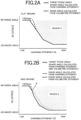
- Figs. 2A and 2B show an example of the relationship between the charging efficiency and the intake valve opening timing on each of the flat ground and the high ground.
- the phase is advanced on the minus side, and retarded on the plus side, and the region C is a region where the target intake air amount cannot be realized if the valve opening timing is set within this region.
- Fig. 2A is a graph for the flat ground
- Fig. 2B is a graph for the high ground
- the region C increases in range on the high ground.
- the graph indicated by a solid line shows the Ec target phase angle with the charging efficiency used as a factor
- the graph indicated by a dashed line shows the Ev target phase angle with the volumetric efficiency used as a factor.
- both the Ec target phase angle and the Ev target phase angle are nearly in agreement.
- the Ec target phase angle with the charging efficiency used as the factor enters the region C beyond the point X, whereas the Ev target phase angle with the volumetric efficiency used as the factor is outside the region C.
- the Ec target phase angle involving the charging efficiency as the factor is selected for the flat ground and up to the point X on the high ground.
- the Ev target phase angle is located on the advanced angle side relative to the Ec target phase angle beyond the point X, the Ev target phase angle is selected.
- Figs. 3A and 3B are graphs each showing an example of the relationship between the charging efficiency and the phase of the exhaust valve opening timing, Fig. 3A being for the flat ground, and Fig. 3B being for the high ground.
- the Ec target phase angle involving the charging efficiency as the factor is selected eventually in the entire region.
- the Ec target phase angle involving the charging efficiency as the factor is selected until the point X is exceeded.
- the Ev target phase angle using the volumetric efficiency as the factor which is situated on the advanced angle side, is adopted, because the Ec target phase angle involving the charging efficiency as the factor and the Ev target phase angle using the volumetric efficiency as the factor are different from each other.
- Fig. 4 is a view illustrating an example of a timing chart according to the embodiment, showing the relationship among the opening of the accelerator, the rotational speed of the engine, the pressure of the intake manifold, the amount of air, and the intake VVT phase angle during a travel on the high ground.
- the intake VVT phase angle is represented as the Ec target phase angle with the charging efficiency used as the factor, and the Ev target phase angle with the volumetric efficiency used as the factor.
- the amount of air is expressed as the charging efficiency and the volumetric efficiency.
- the timing chart also shows these parameters as Examples where the aforementioned control of the embodiment was exercised, and Comparative Examples where such control was not performed.
- Illustrated is a state where the accelerator is open to perform low pressure acceleration. In this state, the engine speed rises, and the pressure of the intake manifold also increases. On the flat ground where the atmospheric pressure is relatively high as shown in Fig. 2A , for example, the charging efficiency Ec also increases to a value close to its maximum value during a high load travel (a case where the opening of the TPS is nearly full) . In this case, the Ec target phase angle is present on the retarded angle side relative to the Ev target phase angle, so that the Ec target phase angle is selected.
- the Ec target phase angle is present on the advanced angle side relative to the Ev target phase angle.
- the Ev target phase angle using the volumetric efficiency as the factor is adopted. Consequently, as compared with the Comparative Example adopting the Ec target phase angle as is, the Example adopting the Ev target phase angle provides a sufficient amount of air, and has the volumetric efficiency and the charging efficiency greater than those in the Comparative Example.
- the engine to which the control device of the present embodiment is applied is equipped with a turbocharger being a supercharging means which rotates a turbine disposed in an exhaust system by exhaust to rotate a compressor disposed in an intake system, thereby supercharging intake air.
- a turbocharger being a supercharging means which rotates a turbine disposed in an exhaust system by exhaust to rotate a compressor disposed in an intake system, thereby supercharging intake air.
- the volumetric efficiency valve opening timing calculation unit 142 calculates the latest timing of the valve opening timings, at which supercharging by the turbocharger is achievable, as the valve opening timing of the intake valve 22, if the target torque calculated by the target torque calculation means 110 is in a range where supercharging by the turbocharger is performed.
- the volumetric efficiency valve opening timing can be used as a valve opening timing capable of stable combustion, even if the superchargeable region changes under the influence of atmospheric pressure (height above sea level).
- volumetric efficiency valve opening timing calculation unit 142 prefferably set the valve opening timing of the intake valve 22 to the latest timing, even if the target torque calculated by the target torque calculation means 110 is in a range where supercharging by the turbocharger is not performed.
- the volumetric efficiency valve opening timing is set at the most retarded angle. By so doing, the charging efficiency valve opening timing is reliably selected, and frequent switching between the charging efficiency valve opening timing and the volumetric efficiency valve opening timing can be prevented.
- the present invention has been described, with the manifold fuel injection engine being taken as the example. Needless to say, however, the present invention can be employed in other types of engines such as the direct injection type.
Landscapes
- Engineering & Computer Science (AREA)
- Mechanical Engineering (AREA)
- General Engineering & Computer Science (AREA)
- Chemical & Material Sciences (AREA)
- Combustion & Propulsion (AREA)
- Output Control And Ontrol Of Special Type Engine (AREA)
- Combined Controls Of Internal Combustion Engines (AREA)
Claims (2)
- Steuerungsvorrichtung (100) für einen Verbrennungsmotor (11) mit einem variablen Ventilzeitsteuerungsmechanismus (30, 31), der eine Öffnungs- oder Schließzeit eines Ansaugventils (22) und/oder eines Ausstoßventils (28) ändert, aufweisend:eine Detektionseinrichtung (44) zum Detektieren von Atmosphärendruck;eine erste Berechnungseinrichtung (120) zum Berechnen einer Ladeeffizienz auf Basis einer durch einen Ansaugluft-Strompfad strömenden Luftmenge;eine zweite Berechnungseinrichtung (130) zum Berechnen einer Volumeneffizienz aus der Luftmenge und dem von der Detektionseinrichtung detektieren Atmosphärendruck; undeine Einstelleinrichtung (140) zum Einstellen der Ventilöffnungszeit des Ansaugventils mithilfe des variablen Ventilzeitsteuerungsmechanismus,wobei die Einstelleinrichtungeine erste Berechnungseinheit (141) zum Berechnen der Ventilöffnungszeit des Ansaugventils auf Basis der von der ersten Berechnungseinrichtung berechneten Ladeeffizienz undeine zweite Berechnungseinheit (142) zum Berechnen der Ventilöffnungszeit des Ansaugventils auf Basis der von der zweiten Berechnungseinrichtung berechneten Volumeneffizienz aufweistund die Ventilöffnungszeit oder Ventilöffnungszeiten des Ansaugventils und/oder des Ausstoßventils auf Basis entweder der von der ersten Berechnungseinheit berechneten Ventilöffnungszeit oder der von der zweiten Berechnungseinheit berechneten Ventilöffnungszeit einstellt, wobeidie Einstelleinrichtung die von der ersten Berechnungseinheit berechnete Ladeeffizienz-Ventilöffnungszeit oder die von der zweiten Berechnungseinheit berechnete Volumeneffizienz-Ventilöffnungszeit als die Ventilöffnungszeit des Ansaugventils einstellt, je nachdem welche auf eine fortgeschrittenere Winkelseite eingestellt ist, und wobeider Verbrennungsmotor mit einer Überladeinrichtung ausgestattet ist, unddie zweite Berechnungseinheit den letztmöglichen Zeitpunkt der Ventilöffnungszeiten, an dem Überladen mittels der Überladeinrichtung erreicht werden kann, als die Ventilöffnungszeit des Ansaugventils berechnet, wenn ein von einer Solldrehmoment-Berechnungseinheit (110) berechnetes Solldrehmoment in einem Bereich ist, in dem das Überladen von der Überladeeinrichtung durchgeführt wird.
- Steuerungsvorrichtung für einen Verbrennungsmotor nach Anspruch 1, wobei
die zweite Berechnungseinheit die Ventilöffnungszeit auf den letztmöglichen Zeitpunkt einstellt, wenn das von der Solldrehmoment-Berechnungseinheit berechnete Solldrehmoment in einem Bereich ist, in dem das Überladen von der Überladeeinrichtung nicht durchgeführt wird.
Applications Claiming Priority (1)
| Application Number | Priority Date | Filing Date | Title |
|---|---|---|---|
| JP2018058924A JP7121332B2 (ja) | 2018-03-26 | 2018-03-26 | 内燃機関の制御装置 |
Publications (2)
| Publication Number | Publication Date |
|---|---|
| EP3546729A1 EP3546729A1 (de) | 2019-10-02 |
| EP3546729B1 true EP3546729B1 (de) | 2024-02-21 |
Family
ID=65955091
Family Applications (1)
| Application Number | Title | Priority Date | Filing Date |
|---|---|---|---|
| EP19164635.5A Active EP3546729B1 (de) | 2018-03-26 | 2019-03-22 | Steuerungsvorrichtung für verbrennungsmotor |
Country Status (4)
| Country | Link |
|---|---|
| US (1) | US10794237B2 (de) |
| EP (1) | EP3546729B1 (de) |
| JP (1) | JP7121332B2 (de) |
| CN (1) | CN110360014B (de) |
Families Citing this family (6)
| Publication number | Priority date | Publication date | Assignee | Title |
|---|---|---|---|---|
| JP7067003B2 (ja) * | 2017-09-25 | 2022-05-16 | 三菱自動車工業株式会社 | エンジンの制御装置 |
| CN110469416A (zh) * | 2019-09-29 | 2019-11-19 | 潍柴动力股份有限公司 | 一种发动机控制方法、控制装置及发动机 |
| CN113357023B (zh) * | 2021-06-22 | 2022-09-06 | 重庆长安汽车股份有限公司 | 一种可变气门正时系统瞬态控制方法、装置及米勒循环发动机 |
| CN114837766B (zh) * | 2022-05-30 | 2023-09-19 | 中南大学 | 发动机在高原环境的vvt控制方法及系统 |
| JP2024136743A (ja) * | 2023-03-24 | 2024-10-04 | トヨタ自動車株式会社 | 車両 |
| CN117329006A (zh) * | 2023-09-11 | 2024-01-02 | 博格华纳(上海)汽车燃油系统有限公司 | 面向连续可变气门正时相位器的发动机充气效率计算方法 |
Family Cites Families (12)
| Publication number | Priority date | Publication date | Assignee | Title |
|---|---|---|---|---|
| JPH04269339A (ja) * | 1991-02-25 | 1992-09-25 | Mazda Motor Corp | エンジンのバルブタイミング制御装置 |
| JP2749226B2 (ja) | 1992-02-28 | 1998-05-13 | 株式会社日立製作所 | 内燃機関の流入空気量検出装置及びこれを利用した燃料噴射量制御装置 |
| JP3768296B2 (ja) * | 1996-08-05 | 2006-04-19 | 三菱自動車工業株式会社 | 筒内噴射型火花点火式内燃エンジンの制御装置 |
| JP3351268B2 (ja) * | 1996-11-15 | 2002-11-25 | トヨタ自動車株式会社 | 内燃機関のバルブタイミング制御装置 |
| JP3400752B2 (ja) * | 1999-09-06 | 2003-04-28 | 三菱電機株式会社 | 内燃機関用制御装置 |
| JP2004360604A (ja) * | 2003-06-05 | 2004-12-24 | Mitsubishi Motors Corp | 内燃機関の可変バルブタイミング装置 |
| JP2009150345A (ja) * | 2007-12-21 | 2009-07-09 | Hitachi Ltd | 内燃機関の制御装置 |
| JP5120301B2 (ja) | 2009-03-13 | 2013-01-16 | 三菱自動車工業株式会社 | 車両のエンジントルク演算装置 |
| DE102012014713A1 (de) * | 2012-07-25 | 2014-01-30 | Volkswagen Aktiengesellschaft | Verfahren zum Betreiben eines Verbrennungsmotors |
| US9664124B2 (en) * | 2013-11-11 | 2017-05-30 | Fca Us Llc | Techniques for coordinated variable valve timing and electronic throttle control |
| JP6406185B2 (ja) | 2015-09-07 | 2018-10-17 | マツダ株式会社 | エンジンの制御装置 |
| JP7067003B2 (ja) * | 2017-09-25 | 2022-05-16 | 三菱自動車工業株式会社 | エンジンの制御装置 |
-
2018
- 2018-03-26 JP JP2018058924A patent/JP7121332B2/ja active Active
-
2019
- 2019-03-22 EP EP19164635.5A patent/EP3546729B1/de active Active
- 2019-03-25 US US16/363,479 patent/US10794237B2/en active Active
- 2019-03-26 CN CN201910234087.1A patent/CN110360014B/zh active Active
Also Published As
| Publication number | Publication date |
|---|---|
| JP7121332B2 (ja) | 2022-08-18 |
| CN110360014A (zh) | 2019-10-22 |
| JP2019173566A (ja) | 2019-10-10 |
| EP3546729A1 (de) | 2019-10-02 |
| US10794237B2 (en) | 2020-10-06 |
| CN110360014B (zh) | 2022-05-31 |
| US20190292950A1 (en) | 2019-09-26 |
Similar Documents
| Publication | Publication Date | Title |
|---|---|---|
| EP3546729B1 (de) | Steuerungsvorrichtung für verbrennungsmotor | |
| US8571783B2 (en) | Controlling cylinder mixture and turbocharger operation | |
| EP1781942B1 (de) | Zündzeitpunktsteuervorrichtung für brennkraftmotor | |
| US7770393B2 (en) | Control of turbocharger imbalance | |
| US7607416B2 (en) | Engine control device | |
| EP2708721B1 (de) | Steuervorrichtung für einen verbrennungsmotor | |
| EP2514952A1 (de) | Steuerungsvorrichtung für einen verbrennungsmotor | |
| US20170037787A1 (en) | Control Device and Control Method for Internal Combustion Engine | |
| JP4277897B2 (ja) | 内燃機関の制御装置 | |
| US20180266365A1 (en) | Exhaust gas control apparatus of internal combustion engine | |
| US10480434B2 (en) | Control device for internal combustion engine | |
| US7152578B2 (en) | Valve characteristic controlling apparatus and method for internal combustion engine | |
| US8938960B2 (en) | Control apparatus for internal combustion engine | |
| EP3460220B1 (de) | Steuerungsvorrichtung für motor | |
| US10677178B2 (en) | Control device for internal combustion engine | |
| JP2009216035A (ja) | 内燃機関の制御装置 | |
| JP6933154B2 (ja) | 内燃機関の制御装置 | |
| JPH10148141A (ja) | 内燃機関のバルブタイミング制御装置 | |
| JP2004092619A (ja) | 内燃機関の制御装置及び制御方法 | |
| JP6406153B2 (ja) | エンジンの制御装置 | |
| JP2018173016A (ja) | 内燃機関の制御装置 | |
| JP2013072372A (ja) | 内燃機関の制御装置 |
Legal Events
| Date | Code | Title | Description |
|---|---|---|---|
| PUAI | Public reference made under article 153(3) epc to a published international application that has entered the european phase |
Free format text: ORIGINAL CODE: 0009012 |
|
| STAA | Information on the status of an ep patent application or granted ep patent |
Free format text: STATUS: REQUEST FOR EXAMINATION WAS MADE |
|
| 17P | Request for examination filed |
Effective date: 20190422 |
|
| AK | Designated contracting states |
Kind code of ref document: A1 Designated state(s): AL AT BE BG CH CY CZ DE DK EE ES FI FR GB GR HR HU IE IS IT LI LT LU LV MC MK MT NL NO PL PT RO RS SE SI SK SM TR |
|
| AX | Request for extension of the european patent |
Extension state: BA ME |
|
| STAA | Information on the status of an ep patent application or granted ep patent |
Free format text: STATUS: EXAMINATION IS IN PROGRESS |
|
| 17Q | First examination report despatched |
Effective date: 20210503 |
|
| GRAP | Despatch of communication of intention to grant a patent |
Free format text: ORIGINAL CODE: EPIDOSNIGR1 |
|
| STAA | Information on the status of an ep patent application or granted ep patent |
Free format text: STATUS: GRANT OF PATENT IS INTENDED |
|
| RIC1 | Information provided on ipc code assigned before grant |
Ipc: F02D 41/00 20060101ALI20230830BHEP Ipc: F02D 13/02 20060101AFI20230830BHEP |
|
| INTG | Intention to grant announced |
Effective date: 20230914 |
|
| GRAS | Grant fee paid |
Free format text: ORIGINAL CODE: EPIDOSNIGR3 |
|
| GRAA | (expected) grant |
Free format text: ORIGINAL CODE: 0009210 |
|
| STAA | Information on the status of an ep patent application or granted ep patent |
Free format text: STATUS: THE PATENT HAS BEEN GRANTED |
|
| AK | Designated contracting states |
Kind code of ref document: B1 Designated state(s): AL AT BE BG CH CY CZ DE DK EE ES FI FR GB GR HR HU IE IS IT LI LT LU LV MC MK MT NL NO PL PT RO RS SE SI SK SM TR |
|
| REG | Reference to a national code |
Ref country code: GB Ref legal event code: FG4D |
|
| REG | Reference to a national code |
Ref country code: CH Ref legal event code: EP |
|
| REG | Reference to a national code |
Ref country code: DE Ref legal event code: R096 Ref document number: 602019046781 Country of ref document: DE |
|
| REG | Reference to a national code |
Ref country code: IE Ref legal event code: FG4D |
|
| REG | Reference to a national code |
Ref country code: LT Ref legal event code: MG9D |
|
| REG | Reference to a national code |
Ref country code: NL Ref legal event code: MP Effective date: 20240221 |
|
| PG25 | Lapsed in a contracting state [announced via postgrant information from national office to epo] |
Ref country code: IS Free format text: LAPSE BECAUSE OF FAILURE TO SUBMIT A TRANSLATION OF THE DESCRIPTION OR TO PAY THE FEE WITHIN THE PRESCRIBED TIME-LIMIT Effective date: 20240621 |
|
| PG25 | Lapsed in a contracting state [announced via postgrant information from national office to epo] |
Ref country code: LT Free format text: LAPSE BECAUSE OF FAILURE TO SUBMIT A TRANSLATION OF THE DESCRIPTION OR TO PAY THE FEE WITHIN THE PRESCRIBED TIME-LIMIT Effective date: 20240221 |
|
| PG25 | Lapsed in a contracting state [announced via postgrant information from national office to epo] |
Ref country code: GR Free format text: LAPSE BECAUSE OF FAILURE TO SUBMIT A TRANSLATION OF THE DESCRIPTION OR TO PAY THE FEE WITHIN THE PRESCRIBED TIME-LIMIT Effective date: 20240522 |
|
| REG | Reference to a national code |
Ref country code: AT Ref legal event code: MK05 Ref document number: 1659309 Country of ref document: AT Kind code of ref document: T Effective date: 20240221 |
|
| PG25 | Lapsed in a contracting state [announced via postgrant information from national office to epo] |
Ref country code: RS Free format text: LAPSE BECAUSE OF FAILURE TO SUBMIT A TRANSLATION OF THE DESCRIPTION OR TO PAY THE FEE WITHIN THE PRESCRIBED TIME-LIMIT Effective date: 20240521 Ref country code: NL Free format text: LAPSE BECAUSE OF FAILURE TO SUBMIT A TRANSLATION OF THE DESCRIPTION OR TO PAY THE FEE WITHIN THE PRESCRIBED TIME-LIMIT Effective date: 20240221 Ref country code: HR Free format text: LAPSE BECAUSE OF FAILURE TO SUBMIT A TRANSLATION OF THE DESCRIPTION OR TO PAY THE FEE WITHIN THE PRESCRIBED TIME-LIMIT Effective date: 20240221 |
|
| PG25 | Lapsed in a contracting state [announced via postgrant information from national office to epo] |
Ref country code: ES Free format text: LAPSE BECAUSE OF FAILURE TO SUBMIT A TRANSLATION OF THE DESCRIPTION OR TO PAY THE FEE WITHIN THE PRESCRIBED TIME-LIMIT Effective date: 20240221 |
|
| PG25 | Lapsed in a contracting state [announced via postgrant information from national office to epo] |
Ref country code: AT Free format text: LAPSE BECAUSE OF FAILURE TO SUBMIT A TRANSLATION OF THE DESCRIPTION OR TO PAY THE FEE WITHIN THE PRESCRIBED TIME-LIMIT Effective date: 20240221 |
|
| PG25 | Lapsed in a contracting state [announced via postgrant information from national office to epo] |
Ref country code: RS Free format text: LAPSE BECAUSE OF FAILURE TO SUBMIT A TRANSLATION OF THE DESCRIPTION OR TO PAY THE FEE WITHIN THE PRESCRIBED TIME-LIMIT Effective date: 20240521 Ref country code: NO Free format text: LAPSE BECAUSE OF FAILURE TO SUBMIT A TRANSLATION OF THE DESCRIPTION OR TO PAY THE FEE WITHIN THE PRESCRIBED TIME-LIMIT Effective date: 20240521 Ref country code: NL Free format text: LAPSE BECAUSE OF FAILURE TO SUBMIT A TRANSLATION OF THE DESCRIPTION OR TO PAY THE FEE WITHIN THE PRESCRIBED TIME-LIMIT Effective date: 20240221 Ref country code: LT Free format text: LAPSE BECAUSE OF FAILURE TO SUBMIT A TRANSLATION OF THE DESCRIPTION OR TO PAY THE FEE WITHIN THE PRESCRIBED TIME-LIMIT Effective date: 20240221 Ref country code: IS Free format text: LAPSE BECAUSE OF FAILURE TO SUBMIT A TRANSLATION OF THE DESCRIPTION OR TO PAY THE FEE WITHIN THE PRESCRIBED TIME-LIMIT Effective date: 20240621 Ref country code: HR Free format text: LAPSE BECAUSE OF FAILURE TO SUBMIT A TRANSLATION OF THE DESCRIPTION OR TO PAY THE FEE WITHIN THE PRESCRIBED TIME-LIMIT Effective date: 20240221 Ref country code: GR Free format text: LAPSE BECAUSE OF FAILURE TO SUBMIT A TRANSLATION OF THE DESCRIPTION OR TO PAY THE FEE WITHIN THE PRESCRIBED TIME-LIMIT Effective date: 20240522 Ref country code: FI Free format text: LAPSE BECAUSE OF FAILURE TO SUBMIT A TRANSLATION OF THE DESCRIPTION OR TO PAY THE FEE WITHIN THE PRESCRIBED TIME-LIMIT Effective date: 20240221 Ref country code: ES Free format text: LAPSE BECAUSE OF FAILURE TO SUBMIT A TRANSLATION OF THE DESCRIPTION OR TO PAY THE FEE WITHIN THE PRESCRIBED TIME-LIMIT Effective date: 20240221 Ref country code: BG Free format text: LAPSE BECAUSE OF FAILURE TO SUBMIT A TRANSLATION OF THE DESCRIPTION OR TO PAY THE FEE WITHIN THE PRESCRIBED TIME-LIMIT Effective date: 20240221 Ref country code: AT Free format text: LAPSE BECAUSE OF FAILURE TO SUBMIT A TRANSLATION OF THE DESCRIPTION OR TO PAY THE FEE WITHIN THE PRESCRIBED TIME-LIMIT Effective date: 20240221 |
|
| PG25 | Lapsed in a contracting state [announced via postgrant information from national office to epo] |
Ref country code: PT Free format text: LAPSE BECAUSE OF FAILURE TO SUBMIT A TRANSLATION OF THE DESCRIPTION OR TO PAY THE FEE WITHIN THE PRESCRIBED TIME-LIMIT Effective date: 20240621 Ref country code: PL Free format text: LAPSE BECAUSE OF FAILURE TO SUBMIT A TRANSLATION OF THE DESCRIPTION OR TO PAY THE FEE WITHIN THE PRESCRIBED TIME-LIMIT Effective date: 20240221 |
|
| PG25 | Lapsed in a contracting state [announced via postgrant information from national office to epo] |
Ref country code: SE Free format text: LAPSE BECAUSE OF FAILURE TO SUBMIT A TRANSLATION OF THE DESCRIPTION OR TO PAY THE FEE WITHIN THE PRESCRIBED TIME-LIMIT Effective date: 20240221 Ref country code: PT Free format text: LAPSE BECAUSE OF FAILURE TO SUBMIT A TRANSLATION OF THE DESCRIPTION OR TO PAY THE FEE WITHIN THE PRESCRIBED TIME-LIMIT Effective date: 20240621 Ref country code: PL Free format text: LAPSE BECAUSE OF FAILURE TO SUBMIT A TRANSLATION OF THE DESCRIPTION OR TO PAY THE FEE WITHIN THE PRESCRIBED TIME-LIMIT Effective date: 20240221 Ref country code: LV Free format text: LAPSE BECAUSE OF FAILURE TO SUBMIT A TRANSLATION OF THE DESCRIPTION OR TO PAY THE FEE WITHIN THE PRESCRIBED TIME-LIMIT Effective date: 20240221 |
|
| PG25 | Lapsed in a contracting state [announced via postgrant information from national office to epo] |
Ref country code: DK Free format text: LAPSE BECAUSE OF FAILURE TO SUBMIT A TRANSLATION OF THE DESCRIPTION OR TO PAY THE FEE WITHIN THE PRESCRIBED TIME-LIMIT Effective date: 20240221 |
|
| PG25 | Lapsed in a contracting state [announced via postgrant information from national office to epo] |
Ref country code: SM Free format text: LAPSE BECAUSE OF FAILURE TO SUBMIT A TRANSLATION OF THE DESCRIPTION OR TO PAY THE FEE WITHIN THE PRESCRIBED TIME-LIMIT Effective date: 20240221 |
|
| PG25 | Lapsed in a contracting state [announced via postgrant information from national office to epo] |
Ref country code: CZ Free format text: LAPSE BECAUSE OF FAILURE TO SUBMIT A TRANSLATION OF THE DESCRIPTION OR TO PAY THE FEE WITHIN THE PRESCRIBED TIME-LIMIT Effective date: 20240221 Ref country code: EE Free format text: LAPSE BECAUSE OF FAILURE TO SUBMIT A TRANSLATION OF THE DESCRIPTION OR TO PAY THE FEE WITHIN THE PRESCRIBED TIME-LIMIT Effective date: 20240221 |
|
| PG25 | Lapsed in a contracting state [announced via postgrant information from national office to epo] |
Ref country code: SK Free format text: LAPSE BECAUSE OF FAILURE TO SUBMIT A TRANSLATION OF THE DESCRIPTION OR TO PAY THE FEE WITHIN THE PRESCRIBED TIME-LIMIT Effective date: 20240221 |
|
| PG25 | Lapsed in a contracting state [announced via postgrant information from national office to epo] |
Ref country code: SM Free format text: LAPSE BECAUSE OF FAILURE TO SUBMIT A TRANSLATION OF THE DESCRIPTION OR TO PAY THE FEE WITHIN THE PRESCRIBED TIME-LIMIT Effective date: 20240221 Ref country code: SK Free format text: LAPSE BECAUSE OF FAILURE TO SUBMIT A TRANSLATION OF THE DESCRIPTION OR TO PAY THE FEE WITHIN THE PRESCRIBED TIME-LIMIT Effective date: 20240221 Ref country code: RO Free format text: LAPSE BECAUSE OF FAILURE TO SUBMIT A TRANSLATION OF THE DESCRIPTION OR TO PAY THE FEE WITHIN THE PRESCRIBED TIME-LIMIT Effective date: 20240221 Ref country code: EE Free format text: LAPSE BECAUSE OF FAILURE TO SUBMIT A TRANSLATION OF THE DESCRIPTION OR TO PAY THE FEE WITHIN THE PRESCRIBED TIME-LIMIT Effective date: 20240221 Ref country code: DK Free format text: LAPSE BECAUSE OF FAILURE TO SUBMIT A TRANSLATION OF THE DESCRIPTION OR TO PAY THE FEE WITHIN THE PRESCRIBED TIME-LIMIT Effective date: 20240221 Ref country code: CZ Free format text: LAPSE BECAUSE OF FAILURE TO SUBMIT A TRANSLATION OF THE DESCRIPTION OR TO PAY THE FEE WITHIN THE PRESCRIBED TIME-LIMIT Effective date: 20240221 |
|
| REG | Reference to a national code |
Ref country code: CH Ref legal event code: PL |
|
| PG25 | Lapsed in a contracting state [announced via postgrant information from national office to epo] |
Ref country code: LU Free format text: LAPSE BECAUSE OF NON-PAYMENT OF DUE FEES Effective date: 20240322 |
|
| PG25 | Lapsed in a contracting state [announced via postgrant information from national office to epo] |
Ref country code: MC Free format text: LAPSE BECAUSE OF FAILURE TO SUBMIT A TRANSLATION OF THE DESCRIPTION OR TO PAY THE FEE WITHIN THE PRESCRIBED TIME-LIMIT Effective date: 20240221 |
|
| REG | Reference to a national code |
Ref country code: DE Ref legal event code: R097 Ref document number: 602019046781 Country of ref document: DE |
|
| PG25 | Lapsed in a contracting state [announced via postgrant information from national office to epo] |
Ref country code: MC Free format text: LAPSE BECAUSE OF FAILURE TO SUBMIT A TRANSLATION OF THE DESCRIPTION OR TO PAY THE FEE WITHIN THE PRESCRIBED TIME-LIMIT Effective date: 20240221 Ref country code: LU Free format text: LAPSE BECAUSE OF NON-PAYMENT OF DUE FEES Effective date: 20240322 |
|
| PG25 | Lapsed in a contracting state [announced via postgrant information from national office to epo] |
Ref country code: IT Free format text: LAPSE BECAUSE OF FAILURE TO SUBMIT A TRANSLATION OF THE DESCRIPTION OR TO PAY THE FEE WITHIN THE PRESCRIBED TIME-LIMIT Effective date: 20240221 |
|
| REG | Reference to a national code |
Ref country code: BE Ref legal event code: MM Effective date: 20240331 |
|
| PLBE | No opposition filed within time limit |
Free format text: ORIGINAL CODE: 0009261 |
|
| STAA | Information on the status of an ep patent application or granted ep patent |
Free format text: STATUS: NO OPPOSITION FILED WITHIN TIME LIMIT |
|
| PG25 | Lapsed in a contracting state [announced via postgrant information from national office to epo] |
Ref country code: IT Free format text: LAPSE BECAUSE OF FAILURE TO SUBMIT A TRANSLATION OF THE DESCRIPTION OR TO PAY THE FEE WITHIN THE PRESCRIBED TIME-LIMIT Effective date: 20240221 |
|
| PG25 | Lapsed in a contracting state [announced via postgrant information from national office to epo] |
Ref country code: BE Free format text: LAPSE BECAUSE OF NON-PAYMENT OF DUE FEES Effective date: 20240331 |
|
| PG25 | Lapsed in a contracting state [announced via postgrant information from national office to epo] |
Ref country code: IE Free format text: LAPSE BECAUSE OF NON-PAYMENT OF DUE FEES Effective date: 20240322 |
|
| 26N | No opposition filed |
Effective date: 20241122 |
|
| GBPC | Gb: european patent ceased through non-payment of renewal fee |
Effective date: 20240521 |
|
| PG25 | Lapsed in a contracting state [announced via postgrant information from national office to epo] |
Ref country code: IE Free format text: LAPSE BECAUSE OF NON-PAYMENT OF DUE FEES Effective date: 20240322 Ref country code: BE Free format text: LAPSE BECAUSE OF NON-PAYMENT OF DUE FEES Effective date: 20240331 Ref country code: CH Free format text: LAPSE BECAUSE OF NON-PAYMENT OF DUE FEES Effective date: 20240331 |
|
| PG25 | Lapsed in a contracting state [announced via postgrant information from national office to epo] |
Ref country code: SI Free format text: LAPSE BECAUSE OF FAILURE TO SUBMIT A TRANSLATION OF THE DESCRIPTION OR TO PAY THE FEE WITHIN THE PRESCRIBED TIME-LIMIT Effective date: 20240221 |
|
| PG25 | Lapsed in a contracting state [announced via postgrant information from national office to epo] |
Ref country code: GB Free format text: LAPSE BECAUSE OF NON-PAYMENT OF DUE FEES Effective date: 20240521 |
|
| PG25 | Lapsed in a contracting state [announced via postgrant information from national office to epo] |
Ref country code: CY Free format text: LAPSE BECAUSE OF FAILURE TO SUBMIT A TRANSLATION OF THE DESCRIPTION OR TO PAY THE FEE WITHIN THE PRESCRIBED TIME-LIMIT; INVALID AB INITIO Effective date: 20190322 |
|
| PG25 | Lapsed in a contracting state [announced via postgrant information from national office to epo] |
Ref country code: HU Free format text: LAPSE BECAUSE OF FAILURE TO SUBMIT A TRANSLATION OF THE DESCRIPTION OR TO PAY THE FEE WITHIN THE PRESCRIBED TIME-LIMIT; INVALID AB INITIO Effective date: 20190322 |
|
| PG25 | Lapsed in a contracting state [announced via postgrant information from national office to epo] |
Ref country code: TR Free format text: LAPSE BECAUSE OF FAILURE TO SUBMIT A TRANSLATION OF THE DESCRIPTION OR TO PAY THE FEE WITHIN THE PRESCRIBED TIME-LIMIT Effective date: 20240221 |
|
| PGFP | Annual fee paid to national office [announced via postgrant information from national office to epo] |
Ref country code: DE Payment date: 20260327 Year of fee payment: 8 |
|
| PGFP | Annual fee paid to national office [announced via postgrant information from national office to epo] |
Ref country code: FR Payment date: 20260323 Year of fee payment: 8 |