EP3546324A1 - Stossfängeranordnung für ein kraftfahrzeug - Google Patents
Stossfängeranordnung für ein kraftfahrzeug Download PDFInfo
- Publication number
- EP3546324A1 EP3546324A1 EP19161531.9A EP19161531A EP3546324A1 EP 3546324 A1 EP3546324 A1 EP 3546324A1 EP 19161531 A EP19161531 A EP 19161531A EP 3546324 A1 EP3546324 A1 EP 3546324A1
- Authority
- EP
- European Patent Office
- Prior art keywords
- crashboxflanschplatte
- crash box
- receptacle
- arrangement according
- rear wall
- Prior art date
- Legal status (The legal status is an assumption and is not a legal conclusion. Google has not performed a legal analysis and makes no representation as to the accuracy of the status listed.)
- Granted
Links
- 238000001125 extrusion Methods 0.000 claims description 3
- 238000000034 method Methods 0.000 description 5
- 238000003466 welding Methods 0.000 description 5
- 238000005304 joining Methods 0.000 description 4
- 238000004519 manufacturing process Methods 0.000 description 3
- 238000010521 absorption reaction Methods 0.000 description 2
- 238000003780 insertion Methods 0.000 description 2
- 230000037431 insertion Effects 0.000 description 2
- 230000006735 deficit Effects 0.000 description 1
- 230000003993 interaction Effects 0.000 description 1
- 239000002184 metal Substances 0.000 description 1
Images


Classifications
-
- B—PERFORMING OPERATIONS; TRANSPORTING
- B60—VEHICLES IN GENERAL
- B60R—VEHICLES, VEHICLE FITTINGS, OR VEHICLE PARTS, NOT OTHERWISE PROVIDED FOR
- B60R19/00—Wheel guards; Radiator guards, e.g. grilles; Obstruction removers; Fittings damping bouncing force in collisions
- B60R19/02—Bumpers, i.e. impact receiving or absorbing members for protecting vehicles or fending off blows from other vehicles or objects
- B60R19/24—Arrangements for mounting bumpers on vehicles
- B60R19/26—Arrangements for mounting bumpers on vehicles comprising yieldable mounting means
-
- B—PERFORMING OPERATIONS; TRANSPORTING
- B60—VEHICLES IN GENERAL
- B60D—VEHICLE CONNECTIONS
- B60D1/00—Traction couplings; Hitches; Draw-gear; Towing devices
- B60D1/14—Draw-gear or towing devices characterised by their type
-
- B—PERFORMING OPERATIONS; TRANSPORTING
- B60—VEHICLES IN GENERAL
- B60D—VEHICLE CONNECTIONS
- B60D1/00—Traction couplings; Hitches; Draw-gear; Towing devices
- B60D1/48—Traction couplings; Hitches; Draw-gear; Towing devices characterised by the mounting
- B60D1/56—Traction couplings; Hitches; Draw-gear; Towing devices characterised by the mounting securing to the vehicle bumper
- B60D1/565—Traction couplings; Hitches; Draw-gear; Towing devices characterised by the mounting securing to the vehicle bumper having an eyelet
-
- B—PERFORMING OPERATIONS; TRANSPORTING
- B60—VEHICLES IN GENERAL
- B60R—VEHICLES, VEHICLE FITTINGS, OR VEHICLE PARTS, NOT OTHERWISE PROVIDED FOR
- B60R19/00—Wheel guards; Radiator guards, e.g. grilles; Obstruction removers; Fittings damping bouncing force in collisions
- B60R19/02—Bumpers, i.e. impact receiving or absorbing members for protecting vehicles or fending off blows from other vehicles or objects
- B60R19/24—Arrangements for mounting bumpers on vehicles
- B60R19/26—Arrangements for mounting bumpers on vehicles comprising yieldable mounting means
- B60R19/34—Arrangements for mounting bumpers on vehicles comprising yieldable mounting means destroyed upon impact, e.g. one-shot type
Definitions
- the invention relates to a bumper assembly for a motor vehicle according to the preamble of patent claim 1.
- Such a bumper assembly for a motor vehicle is for example in the DE 10 2011 010 798 A1 shown.
- This bumper assembly for a motor vehicle in this case has a cross member on which are designed as a single-chamber hollow profile crash boxes are arranged with its one end to this cross member.
- the cross member opposite end of the crash boxes Crashboxflanschplatten are arranged, by means of which the bumper assembly can be arranged on a body or a chassis of a motor vehicle.
- a further flange plate is provided on which a sleeve-shaped hole element is arranged with an internal thread into which a towing eye with a corresponding external thread can be arranged detachably.
- This entire flange plate is arranged between the Crashboxflanschplatte and the motor vehicle, wherein the sleeve-shaped hole element of the flange plate protrudes through an opening in the Crashboxflanschplatte in the crash box.
- a mounting opening is provided, through which a corresponding towing can be guided into the crash box and engages by means of its external thread in the internal thread of the sleeve-shaped hole member and thus connectable to the bumper assembly.
- the towing eye then protrudes from the cross member, so that the eyelet is freely accessible and a motor vehicle with such a bumper assembly can be towed to it.
- the bumper arrangement according to the invention for a motor vehicle in this case has a cross member, are coupled to the crash boxes, being arranged on the crash boxes opposite the cross member Crashboxflanschplatten for attaching the crash boxes to a body or a chassis of a motor vehicle.
- at least one Crashboxflanschplatte a extending in the direction of the cross member recording force and / or cohesively disposed, wherein the receptacle for detachable arrangement of a towing device, such as a towing eye, is formed.
- the at least one crash box flange plate is designed as a hollow chamber profile, which is designed to be particularly advantageous in one piece.
- the receptacle for the detachable arrangement of the towing device is arranged directly on the crash box flange plate, wherein the crash box flange plate with the receptacle for the detachable arrangement of the towing device for mounting the bumper assembly can be provided as a unitary, advantageously one-piece component.
- the receptacle for detachable arrangement of the towing device only during assembly of the bumper assembly with the crash box flange.
- the positive, positive and / or cohesive connection of the receptacle to the detachable arrangement of a towing device with the crash box flange plate can be effected by means of a welded connection, a screw connection or the like.
- the receptacle is designed as a threaded sleeve with an internal thread.
- the at least one crash box flange plate is designed as a single-chamber hollow profile.
- Such single-chamber hollow profiles can be produced procedurally in sophisticated processes in a simple manner.
- the same also applies to the configuration of the at least one crash box flange plate as a multi-chamber hollow profile.
- Such hollow profiles also have a very good rigidity, so that even these formed as a hollow chamber profiles Crashboxflanschplatten in the event of a crash in addition to the crash boxes themselves can still convert energy into deformation energy.
- a deflection of the crash box flange plate by tensile forces when towing or lashing the motor vehicle on the recording is prevented. This also increases the safety of the occupants of a motor vehicle with a bumper arrangement according to the invention again.
- the at least one crash box flange plate has a front wall, a rear wall and two side walls connecting the front wall and the rear wall.
- a cavity is formed by the rear wall, the front wall and in the two side walls, in which the single-chamber or multi-chamber hollow profile is formed.
- at least one inner wall connecting the front wall and the rear wall is provided within the crash box flange plate, which preferably extends in the same direction as the side walls.
- the front and rear wall connecting inner walls may be provided other inner walls, which the Connecting side walls together, but also extend in the same direction as the side walls.
- the rear wall has webs which project beyond the side walls.
- a crash box is joined to the front wall of the at least one crash box flange plate.
- the crash box flange plate essentially constitutes an extension of the crash box.
- its design as a hollow chamber profile it also contributes, as already mentioned, to energy absorption in the event of a crash, so that the safety of the motor vehicle occupants of a motor vehicle with a bumper arrangement according to the invention is increased again ,
- crash box it is also possible to add a crash box to the rear wall of the crash box flange plate, in particular in the region of the webs projecting beyond the side walls of the rear wall.
- the hollow chamber of the crash box flange plate then extends into the corresponding crash box. This makes it possible in addition to realize a second level of force bumper system over the deformation length of the crash box.
- the crash box is joined to the front wall in such a way that the crash box is supported on at least one of the side walls or bears against it.
- a better and more stable connection between Crashbox and Crashboxflanschplatte is achieved again.
- the crash box rests on both side walls, not only an improved and more stable connection between crash box and Crashboxflanschplatte is achieved.
- the at least one Crashboxflanschplatte is designed as an extrusion profile.
- Such a refinement of the crash box flange plate permits a simple production of a crash box flange plate according to the invention as an integral component which can be further processed accordingly and significantly less logistical expenditure claimed as a component formed from several parts.
- the crash boxes of the bumper arrangement according to the invention it is possible according to the invention for the crash boxes of the bumper arrangement according to the invention to be designed, on the one hand, as a single-chamber hollow profile and, on the other hand, as a multi-chamber hollow profile.
- Such hollow sections have proven themselves in crash boxes, because they can absorb energy inputs under targeted deformation of the crash boxes in a particularly simple and good way, so that for the entire bumper arrangement results in a particularly good energy absorption capacity, which increases the safety of the vehicle occupants especially in the event of a crash.
- the plurality of chambers are designed in such a way that they extend over the entire longitudinal extension of the crash box and are separated from one another by different walls.
- a through opening is provided within the at least one crash box flange plate from the rear wall to the front wall, into which the receptacle for detachable arrangement of a towing device can be pushed.
- the receptacle for detachable arrangement of a towing device is arranged particularly stable within the Crashboxflanschplatte, as these trained as a hollow profile Crashboxflanschplatte with its rear wall, its front wall and its side walls and optionally in the case of a multi-chamber profile then existing inner walls a particularly good support the inclusion of a detachable arrangement of a towing device can be realized.
- no additional support elements for supporting this receptacle must be used, since such support walls are already present through the different walls within the crash box flange.
- the receptacle is arranged for releasable arrangement of a towing device within one of the crash boxes.
- the receptacle for the detachable arrangement of the towing device within the crash box itself is arranged without contact with the walls of the crash box, so that the deformation or folding behavior is not affected in an impact.
- the receptacle it is naturally also possible for the receptacle to be arranged outside the crash boxes - but also without contact with the walls of the crash box.
- the cross member has a through opening, by means of which the receptacle is designed to be accessible for a releasable towing device.
- a towing device in particular a towing lug
- the crash box flange plate preferably also has an opening, so that the towing device can also be fastened partially projecting through it.
- an external thread is arranged on the towing device, which engages in a corresponding internal thread of the receptacle for the towing device.
- the inner walls connecting the rear wall and the front wall of the Crashboxflanschplatte within the Hollow profiles are diagonally running and possibly formed crossing each other. As a result, a load path is formed within the Crashboxflanschplatte through which shear and tensile forces can be absorbed very well.
- the receptacle is arranged inside or outside the crash box. If the receptacle is arranged outside the crash box, it is not necessary to arrange an opening for the insertion of the detachable towing device into the cross member, since it is accessible outside the crash box.
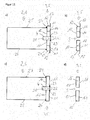
- FIG. 1 shows a first embodiment of a flange plate 3 for a bumper assembly according to the invention.
- the Crashboxflanschplatte 3 is formed as a hollow chamber profile 5 and has a rear wall 11, a front wall 10 and two the rear wall 11 and the front wall 10 connecting side walls 12 and 13.
- the rear wall 11 in this case still has on the side walls 12 and 13 protruding webs 17 and 18, in which mounting holes 20 are arranged, with the help of the Crashboxflanschplatte 3 on a body of a motor vehicle, in particular a longitudinal member of a motor vehicle body detachably, for example by means of screw connections arranged can be.
- the hollow chamber profile 5 of the Crashboxflanschplatte 3 is presently designed as a four-chamber hollow profile, wherein between the rear wall 11 and the front wall 10 four hollow chambers are formed, which are separated by the front wall 10 and the rear wall 11 connecting inner walls 14, 15 and 16.
- the outer hollow chambers are still limited by the side walls 12 and 13.
- the crash box flange plate 3 has an opening 9 which extends from the front side 10 through the hollow chamber profile 5 of the crash box flange plate 3 to the rear wall 11 of the crash box flange plate 3.
- FIG. 2 is the crash box flange plate FIG. 1 in a plan view of the front wall 10 and facing the front wall 10 surfaces of the webs 17 and 18 of the rear wall 11 shown.
- the side walls 12 and 13 connecting the rear wall 11 and the front wall 10 are beveled and thus are not at right angles to the rear wall 11 and the front wall 10 of the crash box flange plate 3, as is in particular also the cross-sectional view through the hollow chamber profile 5 of the crash box flange plate 3 as in FIG. 3 can be seen represented.
- the inner walls 14, 15 and 16 are in contrast to the side walls 12 and 13 perpendicular to the rear wall 11 and the front wall 10 and connect them together.
- the opening 9 extends from the front wall 10 through the entire hollow chamber profile 5 of the crash box flange plate 3 through the rear wall 11.
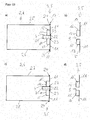
- FIGS. 4 to 6 show the FIGS. 1 to 3 corresponding representations of the Crashboxflanschplatte 3 of FIGS. 1 to 3 , but here through the openings 9 a receptacle 4 for releasable arrangement of a towing device is inserted.
- the FIG. 6 shows a cross-sectional view along the plane BB of FIG. 5 , Since the openings 9 are arranged centrally in the center of the Crashboxflanschplatte 3, the receptacle 4 for releasably arranging a towing device is arranged centrally in the Crashboxflanschplatte.
- the receptacle 4 in this case has an internal thread 21 into which a corresponding external thread of a towing device, for example a towing eye can engage.
- the receptacle 4 is designed as a threaded sleeve with an internal thread 21.
- the receptacle 4 has a collar 22 with which it rests against the rear wall 11 of the crash box flange plate 3 after being pushed through the opening 9 or is supported thereon.
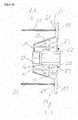
- FIG. 7 is now a perspective view of the Crashboxflanschplatte 3 of FIGS. 1 to 6 shown, wherein on the front wall 10 of the Crashboxflanschplatte 3 a designed as Einzighohlprofil 6 Crashbox is added.
- the joining is advantageously carried out by means of a welding, since both the crash box 2 and the Crashbox flange 3 are made of a weldable metal.
- both the crash box 2 and the crash box flange plate 3 can be designed as an extrusion profile.
- the welded connection can take place over the entire circumference of the crash box 2. Alternatively, it is of course also possible that the joining by means of welding takes place only partially or pointwise.
- FIG. 8 Now, the arrangement of the crash box 2 is shown on the flange plate 3 in a perspective view, wherein at the crash box flange 3 opposite end of the crash box 2 now a cross member 1 is arranged.
- the cross member 1 in this case has an opening 19 which is arranged in the cross member 1, that through this opening 19 a towing device, in particular a towing, pushed through and can be brought into engagement with the receptacle 4.
- the connection between crash box 2 and cross member 1 can also be done by joining by means of a welding process.
- the cross member 1 with the crash box 2 releasably connected, for example by means of a screw connection.
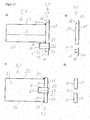
- FIG. 9b is a trained as a hollow chamber profile 5 Crashboxflanschplatte 3 schematically shown in a cross-sectional view and top view, in which case the Crashboxflanschplatte 3 also again a front wall 10, a rear wall 11 and this connecting side walls 12 and 13 has.
- inner walls 14, 15 and 16 are arranged within the hollow chamber profile 5 of the Crashboxflanschplatte 3, which also connect the front wall 10 with the rear wall 11.
- webs 17 and 18 of the rear wall 11 beyond the side walls 12 also.
- the crash box 2 protrudes with side walls 25 and 26 on the front wall 10 of the Crashboxflanschplatte 3 up to the rear wall 11 and is supported with the side wall 26 on the side wall 12 of the Crashboxflanschplatte 3 and with the side wall 25 on the side wall 13 of the Crashboxflanschplatte. 3 from.
- the crash box 6 In the area in which the Crashboxflanschplatte 3 now rests with its side walls 25 and 26 on the rear wall 11 of the Crashboxflanschplatte is the crash box 6 is joined to the crash box flange plate 3 by means of a welded connection 24.
- the inserted through the opening 9 receptacle 4 in this case has a circumferential collar 22 which is supported on the rear wall 11 of the Crashboxflanschplatte 3 and joined by means of a welded joint 23 therewith. Also with the front wall 10, the receptacle 4 is joined by means of a welded joint 23.
- FIG. 9d Now shows a cross-sectional view of the Crashboxflanschplatte 3 of FIG. 9b in a corresponding view from the side.
- FIG. 9c a corresponding side view is shown in cross section through the inner wall 15, in which a crash box 2 is already arranged on the Crashboxflanschplatte 3.
- the Crashboxflanschplatte 3 is joined by means of a welded joint 24 to the upper wall 27 and to the lower wall 28 of the crash box 2.
- the welded joint 24 can thereby circulate the entire crash box 2.
- it may of course also be that the welded joint 24 is formed only partially or punctiform.
- FIG. 10 an embodiment of a Crashboxflanschplatte 3 is shown, to which a crash box 2 is arranged.
- the crash box 2 is in this case again designed as a single-chamber hollow profile 6, while the crash box flange plate 3 is designed as a multi-chamber hollow profile with four hollow chambers.
- the hollow chambers are again formed by the front wall 10, the rear wall 11 and the side walls 12 and 13 and the inner walls 14, 15 and 16.
- the rear wall 11 again on the side walls 12 and 13 protruding ridges 17 and 18, in which mounting holes 20 are arranged for particular detachable arrangement of the Crashboxflanschplatte 3 on a motor vehicle body, in particular a side member of a motor vehicle body.
- the side walls 12 and 13 are formed perpendicular to the front wall 10 and the rear wall 11.
- the crash box 2 is supported with side walls 25 and 26, wherein the side walls 25 and 26 extend to the rear wall 11 and the webs 17 and 18 of the rear wall 11.
- crash box 2 can now be joined again to the crash box flange plate 3 by means of a welded connection (not shown here), wherein this welded connection can again be designed to encircle the entire crash box. Alternatively, it is of course also possible here to create the weld only partially or selectively.
- FIG. 11b is a Crashboxflanschplatte 3 corresponding to the Crashboxflanschplatte the FIG. 5b shown in a cross-sectional view.
- the Crashbox flange 3 of the FIG. 11b corresponds to that of the FIG. 9b
- FIG. 11a is now again the crash box flange 3 of the FIG. 11b shown here, in which case already a crash box 2 is arranged on the Crashboxflanschplatte 3 or joined with this.
- the Crashboxflanschplatte 3 which is also designed as a single-chamber hollow section 6, now joined in the front wall 10 with the Crashboxflanschplatte 3.
- the welded connection 24 can once again be designed to encircle the entire crash box 2 via the side walls 25 and 26 as well as the upper wall 27 and the lower wall 28.
- the receptacle 4 is inserted through the opening 9 of the Crashboxflanschplatte 3 and is supported by a circumferential collar 22 on the back 11 of the Crashboxflanschplatte 3 from. In the region of the circumferential collar 22, the receptacle 4 is joined to the crash box flange plate 3 at its rear side 11 by means of a welded joint 23. Also in this embodiment, the receptacle 4 has an internal thread 21 which corresponds to a corresponding external thread of a towing device, in particular a towing eye.
- FIG. 11d is a cross-sectional view in a side view through the inner wall 15 of the Crashboxflanschplatte 3 shown.
- FIG. 11c the arrangement of the crash box 2 on the Crashboxflanschplatte 3 in a cross-sectional view through the inner wall 15 of the Crashboxflanschplatte 3rd
- FIG. 12 is a further embodiment of a Crashboxflanschplatte 3 shown for a bumper assembly according to the invention, to which already a crash box. 2 is arranged.
- the crash box 2 is again designed as a single-chamber hollow profile 6 and has two side walls 25 and 26, which extend to a front wall 10 of the Crashboxflanschplatte 3 and are joined there via a welded joint 24 with the Crashboxflanschplatte 3.
- the Crashboxflanschplatte 3 is presently again formed as a multi-chamber hollow profile, wherein the individual hollow chambers in turn by the front wall 10 and the rear wall 11 and the connecting these side walls 12 and 13 and inner walls 14 and 16 are formed.
- the Crashboxflanschplatte 3 is in the illustration of FIG.
- the receptacle 4 is supported by a circumferential collar 22 on the rear wall 11 of the Crashboxflanschplatte 3 and is there joined with this. At the, the collar 22 opposite end of the receptacle 4, this has an internal thread 21, which corresponds to an external thread of a towing device in particular a towing.
- the rear wall 11 of the Crashboxflanschplatte 3 has also in this embodiment on the side walls 12 and 13 protruding webs 17 and 18, which for example mounting holes for particular releasable arrangement of the Crashboxflanschplatte 3 on a motor vehicle body, in particular a longitudinal member of a motor vehicle body on.
- FIG. 13b now shows a Crashboxflanschplatte 3 in a cross-sectional view in a view from above wherein the hollow chamber profile 5 of the Crashboxflanschplatte 3 through the front wall 10 and the rear wall 11 and connecting them side walls 12 and 13 is formed.
- FIG. 13a shows a cross-sectional view of the Crashboxflanschplatte the FIG. 13b where a crash box 2 is already arranged on the crash box flange plate 3. It can be clearly seen that the hollow chamber profile 5 of the Crashboxflanschplatte 3 is now entirely within the Einzinghohlprofils 6 of the crash box 2.
- the crash box 2 extends with its side walls 25 and 26 to the webs 17 and 18 of the rear wall 11 of the Crashboxflanschplatte 3 and is joined there by means of a welded joint 24 with the Crashboxflanschplatte 3.
- the side walls 25 and 26 of the crash box 2 are spaced from the side walls 12 and 13 of the crash box flange plate 3.
- the arrangement in the receptacle 4 with internal thread 21 within the opening 9 of the Crashboxflanschplatte. 3 corresponds substantially to that of the previously described embodiments.
- FIGS. 13c and 13d show again corresponding cross-sectional views through the inner wall 15 of the crash box flange 3 so in a side view.
- FIG. 14 is a further embodiment of a Crashboxflanschplatte 3 shown in a cross-sectional view, to which a crash box 2 is already arranged.
- the Crashboxflanschplatte 3 is formed as a multi-chamber hollow section 5, wherein the hollow chambers through the side walls 12 and 13, the front wall 10 and 11 and the parallel thereto inner wall 15 'and perpendicular thereto inner walls 14, 14' and 16 and 16 'are formed.
- the side walls 25 and 26 of the crash box 2 are spaced from the side walls 12 and 13 of the crash box flange plate 3.
- the side walls 12 and 13 of the Crashboxflanschplatte 3 are again at an angle not equal to 90 ° on the rear wall 11 and the front wall 10 of the Crashboxflanschplatte.
- the connection of the Crashboxflanschplatte 3 with the crash box 2 takes place here again via a joining by means of a welding process to form a welded joint 24.
- the receptacle 4 is present again formed with a collar 22 which is supported on the rear wall 11 of the Crashboxflanschplatte 3 and there with this is joined by means of a welded joint 23.
- this receptacle 4 again has an internal thread 21 which corresponds with a corresponding external thread of a towing eye.
- the opening 9 for inserting the receptacle 4 is arranged centrally within the Crashboxflanschplatte 3, in the embodiment of the FIGS. 15a to 15d now shows a Crashboxflanschplatte having an opening 9 outside the center of the Crashboxflanschplatte 3.
- the Crashboxflanschplatte 3 is again formed as a multi-chamber hollow section 5, as in particular in the cross-sectional view of FIG. 15b can be seen.
- the plurality of hollow chambers are again formed by the front wall 10, the rear wall 11 and the connecting side walls 12 and 13 and the inner walls 14 and 16.
- the crash box flange 3 with a crash box. 2 joined wherein the crash box 2 is formed as a multi-chamber hollow section 7.
- the crash box 2 in this case has an inner wall 8 locally cut out in the region of the receptacle 4.
- the side walls 25 and 26 are joined in this embodiment again in the region of the front wall 10 by means of a welded joint 24 with the Crashboxflanschplatte 3.
- FIG. 15d a cross-sectional view is shown from the side.
- the representation of FIG. 15c It can be seen that the inner wall 8 of the crash box 2 is locally cut out in the area of the receptacle 4.
- FIGS. 16a to 16d show now an embodiment, which is essentially that of FIGS. 11a to 11d corresponds, but the Crashboxflanschplatte 3 is not connected here with a designed as a single-chamber hollow profile crash box 2. Rather, the crash box 2 is formed in this embodiment as a multi-chamber hollow profile. In this case, inside the crash box 2 inner walls 8 are arranged, through which the plurality of chambers of the multi-chamber hollow section 7 are formed.
- FIGS. 17a to 17d show now in contrast to the previously described embodiments in which the receptacle 4 was disposed within a hollow chamber of the crash box 2, an embodiment in which the receptacle 4 is disposed outside of the crash box 2.
- FIG. 7b is a cross-sectional view of a Crashboxflanschplatte 3 shown, which corresponds to a side view.
- the Crashboxflanschplatte 3 is formed as a single-chamber hollow profile and has a front wall 10, a rear wall 11 and an upper side wall 12 and a lower side wall 13, wherein the two side walls 12 and 13, the front wall 10 and rear wall 11 connect with each other and are perpendicular to this.
- the rear wall 11 also has in this embodiment with webs 17 and 18 on the side walls 12 addition.
- an opening 9 for a receptacle 4 for the detachable arrangement of a towing device, in particular a towing eye is again provided. However, the opening 9 is not centered in the Crashboxflanschplatte 3, but is arranged in the lower half of the Crashboxflanschplatte 3.
- both a crash box 2 which present as a multi-chamber hollow section 7 with two hollow chambers separated by an inner wall 8 is formed, and arranged a receptacle 4 with an internal thread 21 for the detachable arrangement of a towing device.
- the crash box 2 is joined to the front wall 10 of the Crashboxflanschplatte 3 with upper wall 25 and lower wall 26 by means of welded joints 24.
- the inserted through the opening 9 receptacle 4 in this case has a circumferential collar 22 which is supported on the rear wall 11 of the Crashboxflanschplatte 3 and joined by means of a welded joint 23 therewith.
- the receptacle 4 may be joined by means of a welded joint 23, but this is not shown here.
- the receptacle 4 is arranged outside the crash box 2, so that a cross member arranged on the crash box 2 does not have to have an opening for the insertion of a towing device. Rather, this can be passed below the cross member and connected to the receptacle 4.
- FIG. 17c which shows a plan view from below of the crash box flange plate 3 with the crash box 2 arranged thereon. In particular, it can be seen clearly from the plan view of the lower wall 28 of the crash box 2 that the receptacle 4 is arranged outside the crash box 2.
- FIG. 17 d shows the Crashboxflanschplatte 3 without recording 4 and without it arranged crash box. 2
Abstract
Description
- Die Erfindung betrifft eine Stoßfängeranordnung für ein Kraftfahrzeug nach dem Oberbegriff des Patentanspruchs 1.
- Eine derartige Stoßfängeranordnung für ein Kraftfahrzeug ist beispielsweise in der
DE 10 2011 010 798 A1 gezeigt. Diese Stoßfängeranordnung für ein Kraftfahrzeug weist dabei einen Querträger auf, an dem als Einkammerhohlprofil ausgebildete Crashboxen mit ihrem einen Ende an diesem Querträger angeordnet sind. An dem, dem Querträger gegenüberliegenden Ende der Crashboxen sind Crashboxflanschplatten angeordnet, mit deren Hilfe die Stoßfängeranordnung an einer Karosserie oder einem Fahrgestell eines Kraftfahrzeuges angeordnet werden kann. Bei der dortigen Stoßfängeranordnung ist eine weitere Flanschplatte vorgesehen, an der ein hülsenförmiges Lochelement mit einem Innengewinde angeordnet ist, in welche eine Abschleppöse mit einem entsprechenden Außengewinde lösbar angeordnet werden kann. Diese gesamte Flanschplatte wird dabei zwischen der Crashboxflanschplatte und dem Kraftfahrzeug angeordnet, wobei das hülsenförmige Lochelement der Flanschplatte durch eine Öffnung in der Crashboxflanschplatte in die Crashbox hineinragt. An dem Querträger, der gegenüberliegend der Crashboxflanschplatte an der Crashbox angeordnet ist, ist dabei eine Montageöffnung vorgesehen, durch welche eine entsprechende Abschleppöse in die Crashbox hineingeführt werden kann und mittels ihres Außengewindes in das Innengewinde des hülsenförmigen Lochelementes eingreift und somit mit der Stoßfängeranordnung verbindbar ist. Die Abschleppöse ragt dabei dann aus dem Querträger heraus, sodass die Öse frei zugänglich ist und ein Kraftfahrzeug mit einer derartigen Stoßfängeranordnung daran abgeschleppt werden kann. Ferner wird in derDE 10 2011 010 798 A1 auch noch ein separates auf der Flanschplatte angeordnetes und aus einzelnen Abstützflanschen aufgebautes Stützelement für das Lochelement gezeigt. - Aus der
EP 1 721 786 A1 sind Stoßfängeranordnungen bekannt, bei denen ein integriertes Gewinde in einer Hohlkammer einer asymmetrisch extrudierten und als Mehrkammerprofil ausgebildeten Crashbox verwendet wird, wobei das Gewinde im vorderen beziehungsweise mittleren Längenabschnitt der Crashbox angeordnet ist. Problematisch bei diesen Stoßfängeranordnungen ist ein schlechtes Faltverhalten durch den entsprechenden Gewindeblock. - Es ist daher Aufgabe der Erfindung, eine Stoßfängeranordnung bereitzustellen, wobei in eine derartige Stoßfängeranordnung eine entsprechende Aufnahme zur lösbaren Anordnung einer Abschleppeinrichtung sicher innerhalb dieser Stoßfängeranordnung kraft- und/oder stoffschlüssig ohne Rücksicht auf geringe Toleranzen bei der Aufnahme und der Crashboxen fixiert werden kann. Weiterhin ist es Aufgabe der Erfindung, die Herstellung möglichst einfach mit möglichst wenig Verfahrensschritten zu gewährleisten, wobei zusätzlich auch die Aufwendungen für die Logistik reduziert werden sollen.
- Gelöst wird diese Aufgabe durch eine Stoßfängeranordnung für ein Kraftfahrzeug mit allen Merkmalen des Patentanspruchs 1. Vorteilhafte Ausgestaltungen der Erfindung finden sich in den Unteransprüchen.
- Die erfindungsgemäße Stoßfängeranordnung für ein Kraftfahrzeug weist dabei einen Querträger auf, an dem Crashboxen gekoppelt sind, wobei an den Crashboxen gegenüberliegend dem Querträger Crashboxflanschplatten zum Befestigen der Crashboxen an einer Karosserie oder einem Fahrgestell eines Kraftfahrzeuges angeordnet sind. Dabei ist an wenigstens einer Crashboxflanschplatte eine sich in Richtung des Querträgers erstreckende Aufnahme kraft- und/oder stoffschlüssig angeordnet, wobei die Aufnahme zur lösbaren Anordnung einer Abschleppeinrichtung, wie beispielsweise einer Abschleppöse, ausgebildet ist. Erfindungsgemäß ist dabei die wenigstens eine Crashboxflanschplatte als Hohlkammerprofil ausgebildet, welches besonders vorteilhaft einstückig ausgebildet ist.
- Durch die erfindungsgemäße Stoßfängeranordnung ist es nunmehr ermöglicht, zur Herstellung einer derartigen Stoßfängeranordnung möglichst wenig Teile auf Vorrat zu halten, da die Aufnahme zur lösbaren Anordnung der Abschleppeinrichtung direkt an der Crashboxflanschplatte angeordnet ist, wobei die Crashboxflanschplatte mit der Aufnahme zur lösbaren Anordnung der Abschleppeinrichtung zur Montage der Stoßfängeranordnung als ein einheitliches, vorteilhafterweise einstückiges Bauteil zur Verfügung gestellt werden kann. Alternativ ist es natürlich auch möglich die Aufnahme zur lösbaren Anordnung der Abschleppeinrichtung erst bei der Montage der Stoßfängeranordnung mit der Crashboxflanschplatte zu fügen. Die kraft-, form- und/oder stoffschlüssige Verbindung der Aufnahme zur lösbaren Anordnung einer Abschleppeinrichtung mit der Crashboxflanschplatte kann dabei mittels einer Schweißverbindung, einer Schraubverbindung oder dergleichen erfolgen.
- Weiterhin ist durch die erfindungsgemäße Ausgestaltung der Stoßfängeranordnung keine besondere Rücksicht auf möglichst geringe Toleranzbereiche bei der Aufnahme und den Crashboxen zu berücksichtigen, da diese nicht direkt miteinander gekoppelt werden. Durch die Anordnung der Aufnahme an der Crashboxflanschplatte ist es zudem gewährleistet, dass beim Abschleppen des Kraftfahrzeuges die Crashboxen selbst nicht belastet werden, da die Aufnahme zur lösbaren Anordnung der Abschleppeinrichtung über die Crashboxflanschplatte direkt mit der Karosserie beziehungsweise dem Fahrgestell des Kraftfahrzeuges gekoppelt ist und dabei dann keine Belastung der Crashboxen beziehungsweise Beeinträchtigung des Deformationsverhaltens auftritt.
- Vorteilhafterweise ist die Aufnahme als Gewindehülse mit einem Innengewinde ausgebildet.
- Nach einer ersten vorteilhaften Ausgestaltung der Erfindung ist es vorgesehen, dass die wenigstens eine Crashboxflanschplatte als Einkammerhohlprofil ausgebildet ist. Derartige Einkammerhohlprofile lassen sich verfahrenstechnisch in ausgereiften Verfahren in einfacher Weise herstellen. Das gleiche gilt auch für die Ausgestaltung der wenigstens einen Crashboxflanschplatte als Mehrkammerhohlprofil. Derartige Hohlprofile weisen zudem eine sehr gute Steifigkeit auf, sodass auch diese als Hohlkammerprofile ausgebildeten Crashboxflanschplatten im Falle eines Crashs zusätzlich zu den Crashboxen selbst noch Energie in Verformungsenergie umwandeln können. Eine Durchbiegung der Crashboxflanschplatte durch Zugkräfte beim Abschleppen oder Verzurren des Kraftfahrzeugs über die Aufnahme wird unterbunden. Auch hierdurch ist die Sicherheit der Insassen eines Kraftfahrzeuges mit einer erfindungsgemäßen Stoßfängeranordnung nochmals erhöht.
- Nach einem weiteren Gedanken der Erfindung weist die wenigstens eine Crashboxflanschplatte eine Vorderwand, eine Rückwand sowie zwei die Vorderwand und die Rückwand verbindende Seitenwände auf. Durch diese Ausgestaltung wird durch die Rückwand, die Vorderwand sowie in die beiden Seitenwände ein Hohlraum gebildet, in welchem sich das Einkammer- bzw. Mehrkammerhohlprofil ausbildet. Bei der Ausbildung der Crashboxflanschplatte als Mehrkammerhohlprofil ist innerhalb der Crashboxflanschplatte noch wenigstens eine die Vorderwand und die Rückwand verbindende Innenwand vorgesehen, die sich vorzugsweise in die gleiche Richtung erstreckt, wie die Seitenwände. Allerdings können zudem zusätzlich oder anstatt der die Vorder- und Rückwand verbindende Innenwände andere Innenwände vorgesehen sein, welche die Seitenwände miteinander verbinden, sich aber auch in die gleiche Richtung erstrecken, wie die Seitenwände.
- Weiterhin von Vorteil ist es, wenn die Rückwand Stege aufweist, welche über die Seitenwände hinausragen. Mittels derartiger Stege ist es in einfacher Weise ermöglicht, die Crashboxflanschplatte über Montageöffnungen in diesen Stegen an einer Kraftfahrzeugkarosserie, insbesondere einem Längsträger einer solchen in einfacher Weise insbesondere lösbar zu befestigen, wenn die Montage beispielsweise mit Schrauben erfolgt.
- Nach einer besonderen Ausgestaltung der Erfindung ist auf der Vorderwand der wenigstens einen Crashboxflanschplatte eine Crashbox gefügt. Durch diese Ausgestaltung der Erfindung stellt die Crashboxflanschplatte im Wesentlichen eine Verlängerung der Crashbox dar. Durch die Ausbildung als Hohlkammerprofil trägt sie nämlich wie bereits erwähnt ebenfalls zur Energieabsorption im Falle eines Crashs bei, sodass die Sicherheit der Kraftfahrzeuginsassen eines Kraftfahrzeuges mit einer erfindungsgemäßen Stoßfängeranordnung nochmals erhöht ist.
- Alternativ ist es auch möglich, eine Crashbox auf der Rückwand der Crashboxflanschplatte zu fügen, insbesondere im Bereich der über die Seitenwände hinausragenden Stege der Rückwand. Insoweit reicht die Hohlkammer der Crashboxflanschplatte dann in die entsprechende Crashbox hinein. Damit ist es zusätzlich möglich, ein zweites Kraftniveau Stoßfängersystem über die Deformationslänge der Crashbox zu realisieren.
- Von Vorteil ist es dabei, dass die Crashbox derart auf der Vorderwand gefügt ist, dass sich die Crashbox an wenigstens einer der Seitenwände abstützt beziehungsweise daran anliegt. Hierdurch ist nochmals eine bessere und stabilere Verbindung zwischen Crashbox und Crashboxflanschplatte erreicht. Insbesondere wenn die Crashbox an beiden Seitenwänden anliegt, wird nicht nur eine verbesserte und stabilere Verbindung zwischen Crashbox und Crashboxflanschplatte erreicht.
- Besonders vorteilhaft ist es zudem, wenn die wenigstens eine Crashboxflanschplatte als Extrusionsprofil ausgebildet ist. Eine derartige Ausgestaltung der Crashboxflanschplatte ermöglicht eine einfache Herstellung einer erfindungsgemäßen Crashboxflanschplatte als einstückiges Bauteil, das entsprechend weiterverarbeitet werden kann und deutlich weniger Logistikaufwand beansprucht als ein aus mehreren Einzelteilen gebildetes Bauteil.
- Grundsätzlich ist es erfindungsgemäß möglich, dass die Crashboxen der erfindungsgemäßen Stoßfängeranordnung einerseits als Einkammerhohlprofil und andererseits als Mehrkammerhohlprofil ausgebildet sind. Solche Hohlprofile haben sich bei Crashboxen bewährt, da durch sie in besonders einfacher und guter Weise Energieeinträge unter gezielter Deformation der Crashboxen aufnehmen lassen, sodass dadurch für die gesamte Stoßfängeranordnung ein besonders gutes Energieaufnahmevermögen resultiert, welches insbesondere im Crashfall die Sicherheit der Kraftfahrzeuginsassen erhöht. Bei einem Mehrkammerhohlprofil sind dabei die mehreren Kammern derart ausgebildet, dass sie sich jeweils über die gesamte Längserstreckung der Crashbox erstrecken und dabei durch unterschiedliche Wände voneinander getrennt sind.
- Nach einem weiteren Gedanken der Erfindung ist innerhalb der wenigstens einen Crashboxflanschplatte eine durchgehende Öffnung von der Rückwand zur Vorderwand vorgesehen, in welche die Aufnahme zur lösbaren Anordnung einer Abschleppeinrichtung durchsteckbar ist. Durch eine derartige Ausgestaltung der Erfindung ist es möglich, die Aufnahme zur lösbaren Anordnung einer Abschleppeinrichtung bereits im Vorfeld an der Crashboxflanschplatte zu montieren, wobei sie in einfacher Weise durch die durchgehende Öffnung hindurchgesteckt und dann entsprechend mit entsprechenden Verbindungsverfahren, beispielsweise durch Verschweißen, mit der Crashboxflanschplatte gefügt wird. Durch eine derartige Ausgestaltung der Erfindung wird die Aufnahme zur lösbaren Anordnung einer Abschleppeinrichtung besonders stabil innerhalb der Crashboxflanschplatte angeordnet, da diese als Hohlkammerprofil ausgebildete Crashboxflanschplatte mit ihrer Rückwand, ihrer Vorderwand und ihren Seitenwänden sowie gegebenenfalls im Falle eines Mehrkammerprofils den dann vorhandenen Innenwänden eine besonders gute Abstützung der Aufnahme zur lösbaren Anordnung einer Abschleppeinrichtung realisiert werden kann. Dabei müssen keine zusätzlichen Stützelemente zur Abstützung dieser Aufnahme verwendet werden, da derartige Stützwände durch die unterschiedlichen Wände innerhalb der Crashboxflanschplatte bereits vorhanden sind.
- Nach einer weiteren vorteilhaften Ausgestaltung der Erfindung ist es vorgesehen, dass die Aufnahme zur lösbaren Anordnung einer Abschleppeinrichtung innerhalb einer der Crashboxen angeordnet ist. Hierdurch wird die Aufnahme zur lösbaren Anordnung der Abschleppeinrichtung innerhalb der Crashbox selbst ohne Kontakt zu den Wänden der Crashbox angeordnet, so dass das Deformations- beziehungsweise Faltverhalten bei einem Aufprall nicht beeinträchtigt wird. Allerdings ist es nach einem anderen Gedanken der Erfindung natürlich auch möglich, dass die Aufnahme außerhalb der Crashboxen - aber auch ohne Kontakt zu den Wänden der Crashbox - angeordnet ist.
- Nach einer weiteren Ausgestaltung der Erfindung ist es vorgesehen, dass die Aufnahme zur lösbaren Anordnung einer Abschleppeinrichtung mit der Crashboxflanschplatte, an der sie angeordnet ist, gefügt, insbesondere verschweißt oder verschraubt ist. Dabei hat es sich bewährt, dass die Aufnahme mit der Rückwand und/oder der Vorderwand der Crashboxflanschplatte verschweißt ist. Hierdurch ist in einfacher Weise gewährleistet, dass die Aufnahme zur lösbaren Anordnung einer Abschleppeinrichtung unverlierbar an der entsprechenden Crashboxflanschplatte beziehungsweise an der erfindungsgemäßen Stoßfängeranordnung kraft- und/oder stoffschlüssig angeordnet ist. Dabei kann es vorgesehen sein, dass die Aufnahme mittels Schrumpf- oder Presspassung in der Öffnung innerhalb der Crashboxflanschplatte eingesetzt ist.
- Damit die entsprechende Abschleppeinrichtung mit der Aufnahme zu ihrer lösbaren Anordnung verbunden werden kann, ist es nach einem weiteren Gedanken der Erfindung vorgesehen, dass der Querträger eine durchgehende Öffnung aufweist, mittels welcher die Aufnahme für eine lösbare Abschleppeinrichtung zugänglich ausgebildet ist. Hierdurch ist in besonders einfacher eise ermöglicht, dass eine Abschleppeinrichtung, insbesondere eine Abschleppöse, durch diese Öffnung in dem Querträger hindurchgesteckt werden kann und mit der Aufnahme für die Abschleppeinrichtung verbunden werden kann. Bevorzugt weist auch die Crashboxflanschplatte eine Öffnung auf, so dass die Abschleppeinrichtung auch teilweilweise durch diese hindurchragend befestigt werden kann.
- Vorteilhafterweise ist dabei vorgesehen, dass an der Abschleppeinrichtung ein Außengewinde angeordnet ist, das in ein entsprechendes Innengewinde der Aufnahme für die Abschleppeinrichtung eingreift. Durch ein derartiges Gewindezusammenspiel kann die Abschleppeinrichtung in einfacher und sicherer Weise ohne Verwendung eines Werkzeuges mit der Stoßfängeranordnung verbunden werden.
- Nach einer weiteren Ausgestaltung der Erfindung ist es vorgesehen, dass die die Rückwand und die Vorderwand der Crashboxflanschplatte verbindenden Innenwände innerhalb des Hohlkammerprofils diagonal verlaufend und gegebenenfalls sich kreuzend ausgebildet sind. Hierdurch wird ein Lastpfad innerhalb der Crashboxflanschplatte gebildet, durch den besonders gut Scher- und Zugkräfte aufgenommen werden können.
- Nach einem weiteren Gedanken der Erfindung ist die Aufnahme innerhalb oder außerhalb der Crashbox angeordnet ist. Sofern die Aufnahme außerhalb der Crashbox angeordnet ist, ist es nicht notwendig in den Querträger eine Öffnung zum Durchstecken der lösbaren Abschleppeinrichtung anzuordnen, da sie außerhalb der Crashbox zugänglich ist.
- Weitere Ziele, Vorteile, Merkmale und Anwendungsmöglichkeiten der vorliegenden Erfindung ergeben sich aus der nachfolgenden Beschreibung eines Ausführungsbeispiels anhand der Zeichnung. Dabei bilden alle beschriebenen und/oder bildlich dargestellten Merkmale für sich oder in beliebiger sinnvoller Kombination den Gegenstand der vorliegenden Erfindung, auch unabhängig von ihrer Zusammenfassung in den Ansprüchen oder deren Rückbeziehung.
- Es zeigen:
- Figuren 1 und 3:
- ein erstes Ausführungsbeispiel einer Crashboxflanschplatte für eine erfindungsgemäße Stoßfängeranordnung in verschiedenen Ansichten,
- Figuren 4 bis 6:
- die Crashboxflanschplatte der
Figuren 1 bis 3 mit eingesetzter Aufnahme zur lösbaren Anordnung einer Abschleppeinrichtung in verschiedenen Ansichten, - Figur 7:
- die Crashboxflanschplatte der
Figuren 1 bis 6 mit daran angeordneter Crashbox, - Figur 8:
- die Anordnung von Crashbox und Crashboxflanschplatte gemäß
Figur 7 mit daran angeordnetem Querträger, - Figur 9b und 9d:
- ein Ausführungsbeispiel einer Crashboxflanschplatte für eine erfindungsgemäße Stoßfängeranordnung in zwei unterschiedlichen Ansichten,
- Figur 9a und 9c:
- die Crashboxflanschplatte der Figuren b und d mit daran angeordneter Crashbox,
- Figur 10:
- ein Ausführungsbeispiel einer Crashboxflanschplatte mit daran angeordneter Crashbox in einer perspektivischen Ansicht,
- Figur 11b und 11d:
- ein Ausführungsbeispiel einer Crashboxflanschplatte für eine erfindungsgemäße Stoßfängeranordnung in zwei unterschiedlichen Ansichten,
- Figur 11a und 11c:
- die Crashboxflanschplatte der Figuren b und d mit daran angeordneter Crashbox,
- Figur 12:
- ein Ausführungsbeispiel einer Crashboxflanschplatte mit daran angeordneter Crashbox in einer Querschnittdarstellung,
- Figur 13b und 13d:
- ein Ausführungsbeispiel einer Crashboxflanschplatte für eine erfindungsgemäße Stoßfängeranordnung in zwei unterschiedlichen Ansichten,
- Figur 13a und 13c:
- die Crashboxflanschplatte der Figuren b und d mit daran angeordneter Crashbox,
- Figur 14:
- ein weiteres Ausführungsbeispiel einer Crashboxflanschplatte mit daran angeordneter Crashbox in einer Querschnittdarstellung,
- Figur 15b und 15d:
- ein Ausführungsbeispiel einer Crashboxflanschplatte für eine erfindungsgemäße Stoßfängeranordnung in zwei unterschiedlichen Ansichten,
- Figur 15a und 15c:
- die Crashboxflanschplatte der Figuren b und d mit daran angeordneter Crashbox,
- Figur 16b und 16d:
- ein Ausführungsbeispiel einer Crashboxflanschplatte für eine erfindungsgemäße Stoßfängeranordnung in zwei unterschiedlichen Ansichten,
- Figur 16a und 16c:
- die Crashboxflanschplatte der Figuren b und d mit daran angeordneter Crashbox,
- Figur 17b und 17d:
- ein Ausführungsbeispiel einer Crashboxflanschplatte für eine erfindungsgemäße Stoßfängeranordnung in zwei unterschiedlichen Ansichten und
- Figur 17a und 17c:
- die Crashboxflanschplatte der Figuren b und d mit daran angeordneter Crashbox.
- Die
Figur 1 zeigt ein erstes Ausführungsbeispiel einer Flanschplatte 3 für eine erfindungsgemäße Stoßfängeranordnung. Die Crashboxflanschplatte 3 ist dabei als Hohlkammerprofil 5 ausgebildet und weist eine Rückwand 11, eine Vorderwand 10 sowie zwei die Rückwand 11 und die Vorderwand 10 verbindende Seitenwände 12 und 13 auf. Die Rückwand 11 weist dabei noch über die Seitenwände 12 und 13 hinausragende Stege 17 und 18 auf, in welche Montageöffnungen 20 angeordnet sind, mit deren Hilfe die Crashboxflanschplatte 3 an einer Karosserie eines Kraftfahrzeuges, insbesondere einem Längsträger einer Kraftfahrzeugkarosserie lösbar, beispielsweise mittels Schraubverbindungen, angeordnet werden kann. Das Hohlkammerprofil 5 der Crashboxflanschplatte 3 ist vorliegend als Vierkammerhohlprofil ausgebildet, wobei zwischen der Rückwand 11 und der Vorderwand 10 vier Hohlkammern ausgebildet sind, welche durch die Vorderwand 10 und die Rückwand 11 verbindende Innenwände 14, 15 und 16 voneinander getrennt sind. Die äußeren Hohlkammern werden dabei noch von den Seitenwänden 12 und 13 begrenzt. - Ferner weist die Crashboxflanschplatte 3 eine Öffnung 9 auf, die sich von der Vorderseite 10 durch das Hohlkammerprofil 5 der Crashboxflanschplatte 3 bis zur Rückwand 11 der Crashboxflanschplatte 3 erstreckt.
- In der
Figur 2 ist die Crashboxflanschplatte derFigur 1 in einer Draufsicht auf die Vorderwand 10 und die zur Vorderwand 10 hinweisenden Flächen der Stege 17 und 18 der Rückwand 11 dargestellt. Insbesondere ist hierbei erkennbar, dass die die Rückwand 11 und Vorderwand 10 verbindenden Seitenwände 12 und 13 abgeschrägt ausgebildet sind und somit nicht in einem rechten Winkel zu der Rückwand 11 und der Vorderwand 10 der Crashboxflanschplatte 3 stehen, wie dies insbesondere auch der Querschnittdarstellung durch das Hohlkammerprofil 5 der Crashboxflanschplatte 3 wie inFigur 3 dargestellt zu erkennen ist. Die Innenwände 14, 15 und 16 stehen im Gegensatz zu den Seitenwänden 12 und 13 senkrecht auf der Rückwand 11 und der Vorderwand 10 und verbinden diese miteinander. - In der
Figur 2 ist ebenfalls deutlich zu erkennen, dass sich die Öffnung 9 von der Vorderwand 10 durch das gesamte Hohlkammerprofil 5 der Crashboxflanschplatte 3 hindurch bis durch die Rückwand 11 erstreckt. - Die
Figuren 4 bis 6 zeigen denFiguren 1 bis 3 entsprechende Darstellungen der Crashboxflanschplatte 3 derFiguren 1 bis 3 , wobei jedoch hier durch die Öffnungen 9 eine Aufnahme 4 zur lösbaren Anordnung einer Abschleppeinrichtung durchgesteckt ist. DieFigur 6 zeigt dabei eine Querschnittdarstellung entlang der Ebene B-B derFigur 5 . Da die Öffnungen 9 mittig im Zentrum der Crashboxflanschplatte 3 angeordnet ist, ist auch die Aufnahme 4 zur lösbaren Anordnung einer Abschleppeinrichtung mittig in der Crashboxflanschplatte angeordnet. Die Aufnahme 4 weist dabei ein Innengewinde 21 auf, in welches ein entsprechendes Außengewinde einer Abschleppeinrichtung, beispielsweise eine Abschleppöse eingreifen kann. Im vorliegenden wie auch in den nachfolgend beschriebenen Ausführungsbeispielen ist die Aufnahme 4 als Gewindehülse mit einem Innengewinde 21 ausgebildet. Deutlich zu erkenne ist insbesondere in derFigur 6 , dass die Aufnahme 4 einen Kragen 22 aufweist, mit dem sie nach dem Durchstecken durch die Öffnung 9 in der Crashboxflanschplatte 3 an deren Rückwand 11 anliegt beziehungsweise sich daran abstützt. - In der
Figur 7 ist nunmehr eine perspektivische Ansicht der Crashboxflanschplatte 3 derFiguren 1 bis 6 gezeigt, wobei auf der Vorderwand 10 der Crashboxflanschplatte 3 eine als Einkammerhohlprofil 6 ausgebildete Crashbox gefügt ist. Dabei ist das Fügen vorteilhafterweise mittels eines Verschweißens erfolgt, da sowohl die Crashbox 2 als auch die Crashboxflanschplatte 3 aus einem schweißbaren Metall hergestellt sind. Vorteilhafterweise können dabei sowohl die Crashbox 2 als auch die Crashboxflanschlatte 3 als Extrusionsprofil ausgebildet sein. Die Schweißverbindung kann dabei über den gesamten Umfang der Crashbox 2 erfolgen. Alternativ ist es natürlich auch möglich, dass das Fügen mittels Verschweißen nur abschnittsweise beziehungsweise punktweise erfolgt. - In der
Figur 8 ist nunmehr die Anordnung der Crashbox 2 an der Flanschplatte 3 in einer perspektivischen Darstellung gezeigt, wobei an dem der Crashboxflanschplatte 3 gegenüberliegenden Ende der Crashbox 2 nunmehr ein Querträger 1 angeordnet ist. Der Querträger 1 weist dabei eine Öffnung 19 auf, die derart im Querträger 1 angeordnet ist, dass durch diese Öffnung 19 eine Abschleppeinrichtung, insbesondere eine Abschleppöse, durchgesteckt und in Eingriff mit der Aufnahme 4 gebracht werden kann. Die Verbindung zwischen Crashbox 2 und Querträger 1 kann dabei ebenfalls durch ein Fügen mittels eines Schweißverfahrens erfolgen. Alternativ ist es natürlich auch möglich den Querträger 1 mit der Crashbox 2 lösbar, beispielsweise mittels einer Schraubverbindung zu verbinden. - In der
Figur 9b wird eine als Hohlkammerprofil 5 ausgebildete Crashboxflanschplatte 3schematisch in einer Querschnittdarstellung und Ansicht von oben dargestellt, wobei hierbei die Crashboxflanschplatte 3 ebenfalls wieder eine Vorderwand 10, eine Rückwand 11 und diese verbindende Seitenwände 12 und 13 aufweist. Zudem sind innerhalb des Hohlkammerprofils 5 der Crashboxflanschplatte 3 Innenwände 14, 15 und 16 angeordnet, die ebenfalls die Vorderwand 10 mit der Rückwand 11 verbinden. Auch in diesem Ausführungsbeispiel weisen Stege 17 und 18 der Rückwand 11 über die Seitenwände 12 hinaus. Deutlich zu erkennen ist in der Darstellung derFigur 9b auch die Öffnung 9 innerhalb der Crashboxflanschplatte 3. - In der
Figur 9a ist nunmehr an der Crashboxflanschplatte 3 sowohl eine Crashbox 2, welche vorliegend als Einkammerhohlprofil 6 ausgebildet ist, und eine Aufnahme 4 mit einem Innengewinde 21 zur lösbaren Anordnung einer Abschleppeinrichtung angeordnet. Dabei ragt die Crashbox 2 mit Seitenwänden 25 und 26 über die Vorderwand 10 der Crashboxflanschplatte 3 bis zu deren Hinterwand 11 hinaus und stützt sich dabei mit der Seitenwand 26 an der Seitenwand 12 der Crashboxflanschplatte 3 und mit der Seitenwand 25 an der Seitenwand 13 der Crashboxflanschplatte 3 ab. Im Bereich, in dem die Crashboxflanschplatte 3 mit ihren Seitenwänden 25 und 26 nunmehr an der Rückwand 11 der Crashboxflanschplatte anliegt, ist die Crashbox 6 mittels einer Schweißverbindung 24 mit der Crashboxflanschplatte 3 gefügt. Die durch die Öffnung 9 hindurchgesteckte Aufnahme 4 weist dabei einen umlaufenden Kragen 22 auf, der sich an der Rückwand 11 der Crashboxflanschplatte 3 abstützt und mittels einer Schweißverbindung 23 mit dieser gefügt ist. Auch mit der Vorderwand 10 ist die Aufnahme 4 mittels einer Schweißverbindung 23 gefügt. - Die
Figur 9d zeigt nunmehr eine Querschnittdarstellung der Crashboxflanschplatte 3 derFigur 9b in einer entsprechenden Ansicht von der Seite. In derFigur 9c ist eine entsprechende Seitenansicht im Querschnitt durch die Innenwand 15 gezeigt, in welcher eine Crashbox 2 bereits an der Crashboxflanschplatte 3 angeordnet ist. Auch hierbei ist die Crashboxflanschplatte 3 mittels einer Schweißverbindung 24 an der oberen Wand 27 und an der unteren Wand 28 der Crashbox 2 gefügt. Die Schweißverbindung 24 kann dabei die gesamte Crashbox 2 umlaufen. Alternativ kann es natürlich auch sein, dass die Schweißverbindung 24 nur abschnittsweise oder punktuell ausgebildet ist. - In der
Figur 10 ist ein Ausführungsbeispiel einer Crashboxflanschplatte 3 gezeigt, an welche eine Crashbox 2 angeordnet ist. Die Crashbox 2 ist hierbei wieder als Einkammerhohlprofil 6 ausgebildet, während die Crashboxflanschplatte 3 als Mehrkammerhohlprofil mit vier Hohlkammern ausgebildet ist. Die Hohlkammern sind dabei wieder durch die Vorderwand 10, die Rückwand 11 sowie die Seitenwände 12 und 13 sowie die Innenwände 14, 15 und 16 gebildet. Auch weist in diesem Ausführungsbeispiel die Rückwand 11 wieder über die Seitenwände 12 und 13 hinausragende Stege 17 und 18 auf, in welche Montageöffnungen 20 zur insbesondere lösbaren Anordnung der Crashboxflanschplatte 3 an einer Kraftfahrzeugkarosserie, insbesondere einem Längsträger einer Kraftfahrzeugkarosserie angeordnet sind. - Im Gegensatz zu dem Ausführungsbeispiel der Crashboxflanschplatte 3 der
Figuren 1 bis 6 sind die Seitenwände 12 und 13 hierbei senkrecht zur Vorderwand 10 und zur Rückwand 11 ausgebildet. An diesen Seitenwänden 12 und 13 stützt sich die Crashbox 2 mit Seitenwänden 25 und 26 ab, wobei die Seitenwände 25 und 26 sich bis zur Rückwand 11 bzw. den Stegen 17 und 18 der Rückwand 11 erstrecken. Die obere Wand 27 sowie die hier nicht dargestellte untere Wand 28 der Crashbox 2 erstreckt sich nur bis zur Vorderwand 10. - Die Crashbox 2 kann nunmehr wieder mittels einer hier nicht dargestellten Schweißverbindung mit der Crashboxflanschplatte 3 gefügt sein, wobei diese Schweißverbindung wieder die gesamte Crashbox umlaufend ausgebildet sein kann. Alternativ ist es natürlich auch hierbei möglich, die Schweißverbindung nur abschnittsweise oder punktuell zu erstellen.
- In der
Figur 11b ist eine Crashboxflanschplatte 3 entsprechend der Crashboxflanschplatte derFigur 5b in einer Querschnittdarstellung gezeigt. Die Crashboxflanschplatte 3 derFigur 11b entspricht dabei der derFigur 9b . In derFigur 11a ist nunmehr wieder die Crashboxflanschplatte 3 derFigur 11b gezeigt, wobei hier bereits eine Crashbox 2 an der Crashboxflanschplatte 3 angeordnet beziehungsweise mit dieser gefügt ist. Im Gegensatz zu dem Ausführungsbeispiel derFigur 9a ist die Crashboxflanschplatte 3, die ebenfalls als Einkammerhohlprofil 6 ausgebildet ist, nunmehr im Bereich der Vorderwand 10 mit der Crashboxflanschplatte 3 gefügt. Die Schweißverbindung 24 kann dabei wiederum die gesamte Crashbox 2 über die Seitenwände 25 und 26 sowie die obere Wand 27 und die untere Wand 28 umlaufend ausgebildet sein. Allerdings ist es auch hier möglich, die Schweißverbindung 24 nur abschnittsweise oder punktuell auszubilden. - Auch in diesem Ausführungsbeispiel ist die Aufnahme 4 durch die Öffnung 9 der Crashboxflanschplatte 3 hindurchgesteckt und stützt sich mit einem umlaufenden Kragen 22 an der Rückseite 11 der Crashboxflanschplatte 3 ab. Im Bereich des umlaufenden Kragens 22 ist die Aufnahme 4 mittels einer Schweißverbindung 23 mit der Crashboxflanschplatte 3 an deren Rückseite 11 gefügt. Auch in diesem Ausführungsbeispiel weist die Aufnahme 4 ein Innengewinde 21 auf, welches mit einem entsprechenden Außengewinde einer Abschleppeinrichtung, insbesondere einer Abschleppöse korrespondiert.
- In der
Figur 11d ist eine Querschnittdarstellung in einer Seitenansicht durch die Innenwand 15 der Crashboxflanschplatte 3 gezeigt. - Entsprechend zeigt
Figur 11c die Anordnung der Crashbox 2 an der Crashboxflanschplatte 3 in einer Querschnittdarstellung durch die Innenwand 15 der Crashboxflanschplatte 3. - In der
Figur 12 ist ein weiteres Ausführungsbeispiel einer Crashboxflanschplatte 3 für eine erfindungsgemäße Stoßfängeranordnung gezeigt, an welche bereits eine Crashbox 2 angeordnet ist. Die Crashbox 2 ist dabei wieder als Einkammerhohlprofil 6 ausgebildet und weist zwei Seitenwände 25 und 26 auf, welche sich bis zu einer Vorderwand 10 der Crashboxflanschplatte 3 erstrecken und dort über eine Schweißverbindung 24 mit der Crashboxflanschplatte 3 gefügt sind. Die Crashboxflanschplatte 3 ist vorliegend wieder als Mehrkammerhohlprofil ausgebildet, wobei die einzelnen Hohlkammern wiederum durch die Vorderwand 10 und die Rückwand 11 sowie die diese verbindenden Seitenwände 12 und 13 sowie Innenwände 14 und 16 gebildet sind. In der Crashboxflanschplatte 3 ist in der Darstellung derFigur 12 bereits eine Aufnahme 4 zur lösbaren Anordnung einer Abschleppeinrichtung, insbesondere einer Abschleppöse durch die Öffnung 9 innerhalb der Crashboxflanschplatte 3 durchgesteckt. Die Aufnahme 4 stützt sich dabei mit einem umlaufenden Kragen 22 an der Rückwand 11 der Crashboxflanschplatte 3 ab und ist dort auch mit dieser gefügt. An dem, dem Kragen 22 gegenüberliegenden Ende der Aufnahme 4 weist diese ein Innengewinde 21 auf, welches mit einem Außengewinde einer Abschleppeinrichtung insbesondere einer Abschleppöse korrespondiert. Die Rückwand 11 der Crashboxflanschplatte 3 weist auch in diesem Ausführungsbeispiel über die Seitenwände 12 und 13 hinausragende Stege 17 und 18 auf, welche beispielsweise Montageöffnungen zur insbesondere lösbaren Anordnung der Crashboxflanschplatte 3 an einer Kraftfahrzeugkarosserie, insbesondere einem Längsträger einer Kraftfahrzeugkarosserie, auf. - Die
Figur 13b zeigt nunmehr eine Crashboxflanschplatte 3 in einer Querschnittdarstellung in einer Ansicht von oben wobei das Hohlkammerprofil 5 der Crashboxflanschplatte 3 durch die Vorderwand 10 und die Rückwand 11 sowie diese verbindende Seitenwände 12 und 13 gebildet ist. -
Figur 13a zeigt eine Querschnittdarstellung der Crashboxflanschplatte derFigur 13b , wo bereits eine Crashbox 2 an der Crashboxflanschplatte 3 angeordnet ist. Hierbei ist deutlich erkennbar, dass das Hohlkammerprofil 5 der Crashboxflanschplatte 3 nun gänzlich innerhalb des Einkammerhohlprofils 6 der Crashbox 2 liegt. Die Crashbox 2 erstreckt sich mit ihren Seitenwänden 25 und 26 bis zu den Stegen 17 und 18 der Rückwand 11 der Crashboxflanschplatte 3 und ist dort mittels einer Schweißverbindung 24 mit der Crashboxflanschplatte 3 gefügt. Dabei sind die Seitenwände 25 und 26 der Crashbox 2 von den Seitenwänden 12 und 13 der Crashboxflanschplatte 3 beabstandet. Die Anordnung in der Aufnahme 4 mit Innengewinde 21 innerhalb der Öffnung 9 der Crashboxflanschplatte 3 entspricht im Wesentlichen der, der zuvor beschriebenen Ausführungsbeispiele. - Die
Figuren 13c und 13d zeigen nun wieder entsprechende Querschnittdarstellungen durch die Innenwand 15 der Crashboxflanschplatte 3 also in einer Seitenansicht. - In der
Figur 14 ist ein weiteres Ausführungsbeispiel einer Crashboxflanschplatte 3 in einer Querschnittdarstellung gezeigt, an die bereits eine Crashbox 2 angeordnet ist. Die Crashboxflanschplatte 3 ist dabei als Mehrkammerhohlprofil 5 ausgebildet, wobei die Hohlkammern durch die Seitenwände 12 und 13, die Vorderwand 10 und 11 sowie die dazu parallel verlaufende Innenwand 15' und dazu senkrecht stehenden Innenwände 14, 14' sowie 16 und 16' gebildet sind. - Auch in diesem Ausführungsbeispiel sind die Seitenwände 25 und 26 der Crashbox 2 von den Seitenwänden 12 und 13 der Crashboxflanschplatte 3 beabstandet. Die Seitenwände 12 und 13 der Crashboxflanschplatte 3 stehen dabei wieder in einem Winkel ungleich 90° auf der Rückwand 11 und der Vorderwand 10 der Crashboxflanschplatte. Die Verbindung der Crashboxflanschplatte 3 mit der Crashbox 2 erfolgt auch hierbei wieder über ein Fügen mittels eines Schweißverfahrens unter Ausbildung einer Schweißverbindung 24. Die Aufnahme 4 ist vorliegend wieder mit einem Kragen 22 ausgebildet, der sich an der Rückwand 11 der Crashboxflanschplatte 3 abstützt und dort mit dieser mittels einer Schweißverbindung 23 gefügt ist. Auch diese Aufnahme 4 weist wieder ein Innengewinde 21 auf, das mit einem entsprechenden Außengewinde einer Abschleppöse korrespondiert.
- Während bei allen zuvor beschriebenen Ausführungsbeispielen die Öffnung 9 zum Durchstecken der Aufnahme 4 innerhalb der Crashboxflanschplatte 3 mittig angeordnet ist, ist in dem Ausführungsbeispiel der
Figuren 15a bis 15d nunmehr eine Crashboxflanschplatte gezeigt, die eine Öffnung 9 außerhalb der Mitte der Crashboxflanschplatte 3 aufweist. Die Crashboxflanschplatte 3 ist dabei wieder als Mehrkammerhohlprofil 5 ausgebildet, wie insbesondere in der Querschnittdarstellung derFigur 15b zu erkennen ist. Die mehreren Hohlkammern bilden sich dabei wieder durch die Vorderwand 10, die Rückwand 11 sowie diese verbindenden Seitenwände 12 und 13 sowie die Innenwände 14 und 16 aus. - In der Darstellung der
Figur 15a ist nunmehr die Crashboxflanschplatte 3 mit einer Crashbox 2 gefügt, wobei die Crashbox 2 als Mehrkammerhohlprofil 7 ausgebildet ist. Die Crashbox 2 weist dabei eine im Bereich der Aufnahme 4 lokal ausgeschnittene Innenwand 8 auf. Die Seitenwände 25 und 26 sind in diesem Ausführungsbeispiel wieder im Bereich der Vorderwand 10 mittels einer Schweißverbindung 24 mit der Crashboxflanschplatte 3 gefügt. - In der Darstellung gemäß der
Figur 15d wird eine Querschnittdarstellung von der Seite gezeigt. Insbesondere der Darstellung derFigur 15c ist dabei zu entnehmen, dass die Innenwand 8 der Crashbox 2 dabei im Bereich der Aufnahme 4 lokal ausgeschnitten ist. - Die
Figuren 16a bis 16d zeigen nunmehr ein Ausführungsbeispiel, welches im Wesentlichen dem derFiguren 11a bis 11d entspricht, wobei allerdings die Crashboxflanschplatte 3 hier nicht mit einer als Einkammerhohlprofil ausgebildeten Crashbox 2 verbunden ist. Vielmehr ist die Crashbox 2 in diesem Ausführungsbeispiel als Mehrkammerhohlprofil ausgebildet. Dabei sind innerhalb der Crashbox 2 Innenwände 8 angeordnet, durch welche die mehreren Kammern des Mehrkammerhohlprofils 7 ausgebildet werden. - Die
Figuren 17a bis 17d zeigen nunmehr im Gegensatz zu den bisherig beschriebenen Ausführungsbeispielen, bei denen die Aufnahme 4 innerhalb einer Hohlkammer der Crashbox 2 angeordnet war, ein Ausführungsbeispiel, bei dem die Aufnahme 4 außerhalb der Crashbox 2 angeordnet ist. - In der
Figur 7b ist dabei eine Querschnittdarstellung einer Crashboxflanschplatte 3 gezeigt, die einer Seitenansicht entspricht. Die Crashboxflanschplatte 3 ist dabei als Einkammerhohlprofil ausgebildet und weist eine Vorderwand 10, eine Rückwand 11 sowie eine obere Seitenwand 12 und eine untere Seitenwand 13 auf, wobei die beiden Seitenwände 12 und 13 die Vorderwand 10 und Rückwand 11 miteinander verbinden und auf diesen senkrecht stehen. Die Rückwand 11 weist auch in diesem Ausführungsbeispiel mit Stegen 17 und 18 über die Seitenwände 12 hinaus. Innerhalb der Crashboxflanschplatte 3 ist wieder eine Öffnung 9 für eine Aufnahme 4 zur lösbaren Anordnung einer Abschleppeinrichtung, insbesondere einer Abschleppöse vorgesehen. Die Öffnung 9 liegt aber nicht mittig in der Crashboxflanschplatte 3, sondern ist in der unteren Hälfte der Crashboxflanschplatte 3 angeordnet. - In der
Figur 17a ist nunmehr an der Crashboxflanschplatte 3 sowohl eine Crashbox 2, welche vorliegend als Mehrkammerhohlprofil 7 mit zwei durch eine Innenwand 8 getrennt Hohlkammern eine ausgebildet ist, und eine Aufnahme 4 mit einem Innengewinde 21 zur lösbaren Anordnung einer Abschleppeinrichtung angeordnet. Dabei ist die Crashbox 2 mit oberen Wand 25 und unteren Wand 26 mittels Schweißverbindungen 24 an die Vorderwand 10 der Crashboxflanschplatte 3 gefügt. Die durch die Öffnung 9 hindurchgesteckte Aufnahme 4 weist dabei einen umlaufenden Kragen 22 auf, der sich an der Rückwand 11 der Crashboxflanschplatte 3 abstützt und mittels einer Schweißverbindung 23 mit dieser gefügt ist. Auch mit der Vorderwand 10 kann die Aufnahme 4 mittels einer Schweißverbindung 23 gefügt sein, dies ist hier allerdings nicht dargestellt. Die Aufnahme 4 ist vorliegend außerhalb der Crashbox 2 angeordnet, so dass ein an die Crashbox 2 angeordneter Querträger keine Öffnung zum Durchstecken einer Abschleppeinrichtung aufweisen muss. Vielmehr kann diese unten an dem Querträger vorbeigeführt und mit der Aufnahme 4 verbunden werden. Dies ist insbesondere auch derFigur 17c zu entnehmen, welche eine Draufsicht von unten auf die Crashboxflanschplatte3 mit daran angeordneter Crashbox 2 zeigt. Insbesondere ist hier durch die Draufsicht auf die untere Wand 28 der Crashbox 2 deutlich zu erkennen, dass die Aufnahme 4 außerhalb der Crashbox 2 angeordnet ist.Figur 17 d zeigt die Crashboxflanschplatte 3 ohne Aufnahme 4 und ohne daran angeordnete Crashbox 2. -
- 1
- Querträger
- 2
- Crashbox
- 3
- Crashboxflanschplatte
- 4
- Aufnahme
- 5
- Hohlkammerprofil
- 6
- Einkammerhohlprofil
- 7
- Mehrkammerhohlprofil
- 8
- Innenwand
- 9
- Öffnung
- 10
- Vorderwand
- 11
- Rückwand
- 12
- Seitenwand
- 13
- Seitenwand
- 14
- Innenwand
- 14'
- Innenwand
- 15
- Innenwand
- 15'
- Innenwand
- 16
- Innenwand
- 16'
- Innenwand
- 17
- Steg
- 18
- Steg
- 19
- Öffnung
- 20
- Montageöffnung
- 21
- Innengewinde
- 22
- Kragen
- 23
- Schweißverbindung
- 24
- Schweißverbindung
- 25
- Seitenwand
- 26
- Seitenwand
- 27
- obere Wand
- 28
- untere Wand
Claims (17)
- Stoßfängeranordnung für ein Kraftfahrzeug mit einem Querträger (1), an dem Crashboxen (2) gekoppelt sind, wobei an den Crashboxen (2) gegenüberliegend dem Querträger (1) Crashboxflanschplatten (3) zum Befestigen der Crashboxen (2) an einer Karosserie oder einem Fahrgestell eines Kraftfahrzeugs angeordnet sind, wobei an wenigstens einer Crashboxflanschplatte (3) eine sich in Richtung des Querträgers (1) erstreckende Aufnahme (4) kraft-, form- und/oder stoffschlüssig angeordnet ist, wobei die Aufnahme (4) zur lösbaren Anordnung einer Abschleppeinrichtung ausgebildet ist, dadurch gekennzeichnet, dass die wenigstens eine Crashboxflanschplatte (3) als Hohlkammerprofil (5) ausgebildet ist.
- Stoßfängeranordnung nach Anspruch 1, dadurch gekennzeichnet, dass die wenigstens eine Crashboxflanschplatte (3) als Einkammerhohlprofil ausgebildet ist.
- Stoßfängeranordnung nach Anspruch 1, dadurch gekennzeichnet, dass die wenigstens eine Crashboxflanschplatte (3) als Mehrkammerhohlprofil ausgebildet ist.
- Stoßfängeranordnung nach einem der vorhergehenden Ansprüche, dadurch gekennzeichnet, dass die Crashboxflanschplatte (3) eine Vorderwand (10), eine Rückwand (11) sowie zwei die Vorderwand (10) und die Rückwand (11) verbindende Seitenwände (12, 13) aufweist.
- Stoßfängeranordnung nach einem der Ansprüche 3 oder 4, dadurch gekennzeichnet, dass die Crashboxflanschplatte (3) wenigstens eine die Vorderwand (10) und die Rückwand (11) verbindende Innenwand (14, 15, 16) aufweist.
- Stoßfängeranordnung nach einem der Ansprüche 4 bis 6, dadurch gekennzeichnet, dass die Rückwand (11) Stege (17, 18) aufweist, welche über die Seitenwände (12. 13) hinausragen.
- Stoßfängeranordnung nach einem der Ansprüche 4 bis 6, dadurch gekennzeichnet, dass auf der Vorderwand (10) der wenigstens einen Crashboxflanschplatte (3) eine Crashbox (2) gefügt ist.
- Stoßfängeranordnung nach einem der Ansprüche 4 bis 6, dadurch gekennzeichnet, dass auf der Rückwand (11) der Crashboxflanschplatte (3) eine Crashbox (2) gefügt ist.
- Stoßfängeranordnung nach Anspruch 8, dadurch gekennzeichnet, dass sich die Crashbox (2) an wenigstens einer der Seitenwände (12, 13) abstützt beziehungsweise daran anliegt.
- Stoßfängeranordnung nach einem der vorhergehenden Ansprüche, dadurch gekennzeichnet, dass die wenigstens eine Crashboxflanschplatte (3) als Extrusionsprofil ausgebildet ist.
- Stoßfängeranordnung nach einem der vorhergehenden Ansprüche, dadurch gekennzeichnet, dass die Crashboxen (2) als Einkammerhohlprofil (6) ausgebildet sind.
- Stoßfängeranordnung nach einem der Ansprüche 1 bis 4, dadurch gekennzeichnet, dass die Crashboxen (2) als Mehrkammerprofil (7) ausgebildet sind.
- Stoßfängeranordnung nach einem der vorhergehenden Ansprüche, dadurch gekennzeichnet, dass innerhalb der wenigstens eine Crashboxflanschplatte (3) eine durchgehende Öffnung (8) vorgesehen ist, in welcher die Aufnahme (4) zur lösbaren Anordnung einer Abschleppeinrichtung durchgesteckt ist.
- Stoßfängeranordnung nach einem der vorhergehenden Ansprüche, dadurch gekennzeichnet, dass die Aufnahme (4) mit der Crashboxflanschplatte (3), an der sie angeordnet ist, gefügt ist, wobei sie insbesondere mit der Rückwand (11) und/oder der Vorderwand (10) der Crashboxflanschplatte (3) verschweißt ist.
- Stoßfängeranordnung nach einem der vorhergehenden Ansprüche, dadurch gekennzeichnet, dass der Querträger (1) eine durchgehende Öffnung (19) aufweist, mittels welcher die Aufnahme (4) für eine lösbare Abschleppeinrichtung zugänglich ausgebildet ist.
- Stoßfängeranordnung nach einem der vorhergehenden Ansprüche, dadurch gekennzeichnet, dass die die Rückwand (11) und die Vorderwand (10) der Crashboxflanschplatte (3) verbindenden Innenwände (14, 15, 16) innerhalb des Hohlkammerprofils diagonal verlaufend und gegebenenfalls sich kreuzend ausgebildet sind.
- Stoßfängeranordnung nach einem der vorhergehenden Ansprüche, dadurch gekennzeichnet, dass sich die Aufnahme (4) innerhalb oder außerhalb der Crashbox angeordnet ist.
Applications Claiming Priority (1)
| Application Number | Priority Date | Filing Date | Title |
|---|---|---|---|
| DE102018107487.5A DE102018107487A1 (de) | 2018-03-28 | 2018-03-28 | Stoßfängeranordnung für ein Kraftfahrzeug |
Publications (2)
| Publication Number | Publication Date |
|---|---|
| EP3546324A1 true EP3546324A1 (de) | 2019-10-02 |
| EP3546324B1 EP3546324B1 (de) | 2021-01-27 |
Family
ID=65729169
Family Applications (1)
| Application Number | Title | Priority Date | Filing Date |
|---|---|---|---|
| EP19161531.9A Active EP3546324B1 (de) | 2018-03-28 | 2019-03-08 | Stossfängeranordnung für ein kraftfahrzeug |
Country Status (3)
| Country | Link |
|---|---|
| EP (1) | EP3546324B1 (de) |
| CN (1) | CN110316126B (de) |
| DE (1) | DE102018107487A1 (de) |
Cited By (1)
| Publication number | Priority date | Publication date | Assignee | Title |
|---|---|---|---|---|
| CN113650576A (zh) * | 2021-08-02 | 2021-11-16 | 合肥工业大学 | 一种复式吸能盒及具有该吸能盒的汽车 |
Families Citing this family (2)
| Publication number | Priority date | Publication date | Assignee | Title |
|---|---|---|---|---|
| DE102020114662A1 (de) * | 2020-06-02 | 2021-12-02 | Benteler Automobiltechnik Gmbh | Querträger für ein Stoßfängersystem eines Kraftfahrzeugs sowie Verfahren zur Herstellung eines solchen Querträgers |
| DE102020122965A1 (de) * | 2020-09-02 | 2022-03-03 | ACPS Automotive GmbH | Montagesystem |
Citations (4)
| Publication number | Priority date | Publication date | Assignee | Title |
|---|---|---|---|---|
| JP2008037220A (ja) * | 2006-08-04 | 2008-02-21 | Kobe Steel Ltd | 脱着式牽引フックの取付構造 |
| DE102007060113A1 (de) * | 2007-12-13 | 2009-06-18 | Benteler Automobiltechnik Gmbh | Verfahren zur Herstellung eines Stoßfängers und Stoßfänger |
| JP2012153254A (ja) * | 2011-01-26 | 2012-08-16 | Showa Denko Kk | 車両用衝撃吸収部材 |
| JP2012224099A (ja) * | 2011-04-14 | 2012-11-15 | Toyoda Iron Works Co Ltd | 車両のフック取付構造およびフック取付モジュール |
Family Cites Families (5)
| Publication number | Priority date | Publication date | Assignee | Title |
|---|---|---|---|---|
| EP1721786B1 (de) | 2005-05-13 | 2012-03-28 | Constellium Switzerland AG | Stossfängersystem |
| DE102010006975A1 (de) * | 2010-02-05 | 2011-08-11 | GM Global Technology Operations LLC, ( n. d. Ges. d. Staates Delaware ), Mich. | Kraftfahrzeug-Vorderbau |
| DE102011010798A1 (de) | 2011-02-09 | 2012-08-09 | Benteler Automobiltechnik Gmbh | Stoßfängeranordnung mit Abschleppvorrichtung |
| CN205524081U (zh) * | 2016-01-26 | 2016-08-31 | 北京长城华冠汽车科技股份有限公司 | 一种吸能盒和包括该吸能盒的汽车 |
| CN106043183A (zh) * | 2016-07-29 | 2016-10-26 | 奇瑞新能源汽车技术有限公司 | 汽车前防撞梁总成 |
-
2018
- 2018-03-28 DE DE102018107487.5A patent/DE102018107487A1/de not_active Withdrawn
-
2019
- 2019-03-08 EP EP19161531.9A patent/EP3546324B1/de active Active
- 2019-03-28 CN CN201910241940.2A patent/CN110316126B/zh active Active
Patent Citations (4)
| Publication number | Priority date | Publication date | Assignee | Title |
|---|---|---|---|---|
| JP2008037220A (ja) * | 2006-08-04 | 2008-02-21 | Kobe Steel Ltd | 脱着式牽引フックの取付構造 |
| DE102007060113A1 (de) * | 2007-12-13 | 2009-06-18 | Benteler Automobiltechnik Gmbh | Verfahren zur Herstellung eines Stoßfängers und Stoßfänger |
| JP2012153254A (ja) * | 2011-01-26 | 2012-08-16 | Showa Denko Kk | 車両用衝撃吸収部材 |
| JP2012224099A (ja) * | 2011-04-14 | 2012-11-15 | Toyoda Iron Works Co Ltd | 車両のフック取付構造およびフック取付モジュール |
Cited By (1)
| Publication number | Priority date | Publication date | Assignee | Title |
|---|---|---|---|---|
| CN113650576A (zh) * | 2021-08-02 | 2021-11-16 | 合肥工业大学 | 一种复式吸能盒及具有该吸能盒的汽车 |
Also Published As
| Publication number | Publication date |
|---|---|
| CN110316126B (zh) | 2022-12-02 |
| DE102018107487A1 (de) | 2019-10-02 |
| CN110316126A (zh) | 2019-10-11 |
| EP3546324B1 (de) | 2021-01-27 |
Similar Documents
| Publication | Publication Date | Title |
|---|---|---|
| DE102007035483B4 (de) | Crasheinrichtung | |
| EP3546324B1 (de) | Stossfängeranordnung für ein kraftfahrzeug | |
| DE19545069B4 (de) | Stoßstange mit Querträger in Halbschalenbauweise | |
| DE10321573B4 (de) | Crashstruktur für eine Kraftwagen-Rohbaustruktur | |
| EP2508407A1 (de) | Gerüst, insbesondere für elektrische Einrichtungen in einem Schienenfahrzeug, und Verfahren zur Herstellung des Gerüsts | |
| DE102012018708A1 (de) | Fahrzeug | |
| EP2698295B1 (de) | Längenverstellbares Teleskoprohr, Stützwinde und Montageverfahren | |
| DE102013114789B4 (de) | Verfahren zur Herstellung von Hohlprofilen sowie Hohlprofil | |
| DE102015113773B3 (de) | Stoßfängeranordnung für ein Kraftfahrzeug | |
| EP1710149B2 (de) | Schlussquerträger für ein Nutzfahrzeug | |
| DE102014018755B3 (de) | Fahrzeugkarosserie | |
| EP3519213A1 (de) | Anhängekupplung mit einem zuganker | |
| DE102008020051A1 (de) | Crashbox für eine Karosserie eines Kraftwagens | |
| DE102015210293A1 (de) | Karosseriestruktur für ein zweispuriges Fahrzeug | |
| DE102016000948A1 (de) | Befestigungsanordnung eines Frontquerträgers an einem Energieabsorptionselement eines Längsträgers einer Kraftwagenkarosserie | |
| DE102018106224B4 (de) | Stoßfängeranordnung für ein Kraftfahrzeug | |
| EP3715184B1 (de) | Stossfängeranordnung | |
| DE102012019379A1 (de) | Energieabsorptionselement für einen Kraftwagen | |
| EP3468821A1 (de) | Strukturbauteil für ein kraftfahrzeug mit verstärkungselement | |
| WO2016184554A1 (de) | Bauteilverbund für einen rohbau eines kraftwagens | |
| DE10100333A1 (de) | Fahrzeugkarosserie- und Rahmenanordnung | |
| DE10058998C1 (de) | Stoßfängereinheit eines Kraftfahrzeuges | |
| DE102010013283B4 (de) | Stoßfänger eines Kraftfahrzeugs sowie Verfahren zur Herstellung eines Stoßfängers | |
| DE102020132481B4 (de) | Energieabsorptionsvorrichtung für eine Stoßfängeranordnung eines Kraftfahrzeuges sowie Stoßfängeranordnung eines Kraftfahrzeuges | |
| DE10036790B4 (de) | Befestigungsanordnung zum Fügen von benachbarten Leichtbauplatten einer Fahrzeugtragstruktur |
Legal Events
| Date | Code | Title | Description |
|---|---|---|---|
| PUAI | Public reference made under article 153(3) epc to a published international application that has entered the european phase |
Free format text: ORIGINAL CODE: 0009012 |
|
| STAA | Information on the status of an ep patent application or granted ep patent |
Free format text: STATUS: THE APPLICATION HAS BEEN PUBLISHED |
|
| AK | Designated contracting states |
Kind code of ref document: A1 Designated state(s): AL AT BE BG CH CY CZ DE DK EE ES FI FR GB GR HR HU IE IS IT LI LT LU LV MC MK MT NL NO PL PT RO RS SE SI SK SM TR |
|
| AX | Request for extension of the european patent |
Extension state: BA ME |
|
| STAA | Information on the status of an ep patent application or granted ep patent |
Free format text: STATUS: REQUEST FOR EXAMINATION WAS MADE |
|
| 17P | Request for examination filed |
Effective date: 20200402 |
|
| RBV | Designated contracting states (corrected) |
Designated state(s): AL AT BE BG CH CY CZ DE DK EE ES FI FR GB GR HR HU IE IS IT LI LT LU LV MC MK MT NL NO PL PT RO RS SE SI SK SM TR |
|
| GRAP | Despatch of communication of intention to grant a patent |
Free format text: ORIGINAL CODE: EPIDOSNIGR1 |
|
| STAA | Information on the status of an ep patent application or granted ep patent |
Free format text: STATUS: GRANT OF PATENT IS INTENDED |
|
| INTG | Intention to grant announced |
Effective date: 20200818 |
|
| GRAS | Grant fee paid |
Free format text: ORIGINAL CODE: EPIDOSNIGR3 |
|
| GRAA | (expected) grant |
Free format text: ORIGINAL CODE: 0009210 |
|
| STAA | Information on the status of an ep patent application or granted ep patent |
Free format text: STATUS: THE PATENT HAS BEEN GRANTED |
|
| AK | Designated contracting states |
Kind code of ref document: B1 Designated state(s): AL AT BE BG CH CY CZ DE DK EE ES FI FR GB GR HR HU IE IS IT LI LT LU LV MC MK MT NL NO PL PT RO RS SE SI SK SM TR |
|
| REG | Reference to a national code |
Ref country code: GB Ref legal event code: FG4D Free format text: NOT ENGLISH |
|
| REG | Reference to a national code |
Ref country code: CH Ref legal event code: EP |
|
| REG | Reference to a national code |
Ref country code: AT Ref legal event code: REF Ref document number: 1358104 Country of ref document: AT Kind code of ref document: T Effective date: 20210215 |
|
| REG | Reference to a national code |
Ref country code: IE Ref legal event code: FG4D Free format text: LANGUAGE OF EP DOCUMENT: GERMAN |
|
| REG | Reference to a national code |
Ref country code: DE Ref legal event code: R096 Ref document number: 502019000752 Country of ref document: DE |
|
| REG | Reference to a national code |
Ref country code: NL Ref legal event code: MP Effective date: 20210127 |
|
| REG | Reference to a national code |
Ref country code: LT Ref legal event code: MG9D |
|
| PG25 | Lapsed in a contracting state [announced via postgrant information from national office to epo] |
Ref country code: BG Free format text: LAPSE BECAUSE OF FAILURE TO SUBMIT A TRANSLATION OF THE DESCRIPTION OR TO PAY THE FEE WITHIN THE PRESCRIBED TIME-LIMIT Effective date: 20210427 Ref country code: HR Free format text: LAPSE BECAUSE OF FAILURE TO SUBMIT A TRANSLATION OF THE DESCRIPTION OR TO PAY THE FEE WITHIN THE PRESCRIBED TIME-LIMIT Effective date: 20210127 Ref country code: GR Free format text: LAPSE BECAUSE OF FAILURE TO SUBMIT A TRANSLATION OF THE DESCRIPTION OR TO PAY THE FEE WITHIN THE PRESCRIBED TIME-LIMIT Effective date: 20210428 Ref country code: FI Free format text: LAPSE BECAUSE OF FAILURE TO SUBMIT A TRANSLATION OF THE DESCRIPTION OR TO PAY THE FEE WITHIN THE PRESCRIBED TIME-LIMIT Effective date: 20210127 Ref country code: LT Free format text: LAPSE BECAUSE OF FAILURE TO SUBMIT A TRANSLATION OF THE DESCRIPTION OR TO PAY THE FEE WITHIN THE PRESCRIBED TIME-LIMIT Effective date: 20210127 Ref country code: NO Free format text: LAPSE BECAUSE OF FAILURE TO SUBMIT A TRANSLATION OF THE DESCRIPTION OR TO PAY THE FEE WITHIN THE PRESCRIBED TIME-LIMIT Effective date: 20210427 Ref country code: PT Free format text: LAPSE BECAUSE OF FAILURE TO SUBMIT A TRANSLATION OF THE DESCRIPTION OR TO PAY THE FEE WITHIN THE PRESCRIBED TIME-LIMIT Effective date: 20210527 |
|
| PG25 | Lapsed in a contracting state [announced via postgrant information from national office to epo] |
Ref country code: RS Free format text: LAPSE BECAUSE OF FAILURE TO SUBMIT A TRANSLATION OF THE DESCRIPTION OR TO PAY THE FEE WITHIN THE PRESCRIBED TIME-LIMIT Effective date: 20210127 Ref country code: PL Free format text: LAPSE BECAUSE OF FAILURE TO SUBMIT A TRANSLATION OF THE DESCRIPTION OR TO PAY THE FEE WITHIN THE PRESCRIBED TIME-LIMIT Effective date: 20210127 Ref country code: LV Free format text: LAPSE BECAUSE OF FAILURE TO SUBMIT A TRANSLATION OF THE DESCRIPTION OR TO PAY THE FEE WITHIN THE PRESCRIBED TIME-LIMIT Effective date: 20210127 Ref country code: SE Free format text: LAPSE BECAUSE OF FAILURE TO SUBMIT A TRANSLATION OF THE DESCRIPTION OR TO PAY THE FEE WITHIN THE PRESCRIBED TIME-LIMIT Effective date: 20210127 |
|
| PG25 | Lapsed in a contracting state [announced via postgrant information from national office to epo] |
Ref country code: IS Free format text: LAPSE BECAUSE OF FAILURE TO SUBMIT A TRANSLATION OF THE DESCRIPTION OR TO PAY THE FEE WITHIN THE PRESCRIBED TIME-LIMIT Effective date: 20210527 |
|
| REG | Reference to a national code |
Ref country code: DE Ref legal event code: R097 Ref document number: 502019000752 Country of ref document: DE |
|
| PG25 | Lapsed in a contracting state [announced via postgrant information from national office to epo] |
Ref country code: SM Free format text: LAPSE BECAUSE OF FAILURE TO SUBMIT A TRANSLATION OF THE DESCRIPTION OR TO PAY THE FEE WITHIN THE PRESCRIBED TIME-LIMIT Effective date: 20210127 Ref country code: EE Free format text: LAPSE BECAUSE OF FAILURE TO SUBMIT A TRANSLATION OF THE DESCRIPTION OR TO PAY THE FEE WITHIN THE PRESCRIBED TIME-LIMIT Effective date: 20210127 Ref country code: CZ Free format text: LAPSE BECAUSE OF FAILURE TO SUBMIT A TRANSLATION OF THE DESCRIPTION OR TO PAY THE FEE WITHIN THE PRESCRIBED TIME-LIMIT Effective date: 20210127 Ref country code: MC Free format text: LAPSE BECAUSE OF FAILURE TO SUBMIT A TRANSLATION OF THE DESCRIPTION OR TO PAY THE FEE WITHIN THE PRESCRIBED TIME-LIMIT Effective date: 20210127 |
|
| PG25 | Lapsed in a contracting state [announced via postgrant information from national office to epo] |
Ref country code: DK Free format text: LAPSE BECAUSE OF FAILURE TO SUBMIT A TRANSLATION OF THE DESCRIPTION OR TO PAY THE FEE WITHIN THE PRESCRIBED TIME-LIMIT Effective date: 20210127 Ref country code: RO Free format text: LAPSE BECAUSE OF FAILURE TO SUBMIT A TRANSLATION OF THE DESCRIPTION OR TO PAY THE FEE WITHIN THE PRESCRIBED TIME-LIMIT Effective date: 20210127 Ref country code: SK Free format text: LAPSE BECAUSE OF FAILURE TO SUBMIT A TRANSLATION OF THE DESCRIPTION OR TO PAY THE FEE WITHIN THE PRESCRIBED TIME-LIMIT Effective date: 20210127 |
|
| PLBE | No opposition filed within time limit |
Free format text: ORIGINAL CODE: 0009261 |
|
| STAA | Information on the status of an ep patent application or granted ep patent |
Free format text: STATUS: NO OPPOSITION FILED WITHIN TIME LIMIT |
|
| REG | Reference to a national code |
Ref country code: BE Ref legal event code: MM Effective date: 20210331 |
|
| 26N | No opposition filed |
Effective date: 20211028 |
|
| PG25 | Lapsed in a contracting state [announced via postgrant information from national office to epo] |
Ref country code: ES Free format text: LAPSE BECAUSE OF FAILURE TO SUBMIT A TRANSLATION OF THE DESCRIPTION OR TO PAY THE FEE WITHIN THE PRESCRIBED TIME-LIMIT Effective date: 20210127 Ref country code: AL Free format text: LAPSE BECAUSE OF FAILURE TO SUBMIT A TRANSLATION OF THE DESCRIPTION OR TO PAY THE FEE WITHIN THE PRESCRIBED TIME-LIMIT Effective date: 20210127 Ref country code: IE Free format text: LAPSE BECAUSE OF NON-PAYMENT OF DUE FEES Effective date: 20210308 Ref country code: LU Free format text: LAPSE BECAUSE OF NON-PAYMENT OF DUE FEES Effective date: 20210308 |
|
| PG25 | Lapsed in a contracting state [announced via postgrant information from national office to epo] |
Ref country code: SI Free format text: LAPSE BECAUSE OF FAILURE TO SUBMIT A TRANSLATION OF THE DESCRIPTION OR TO PAY THE FEE WITHIN THE PRESCRIBED TIME-LIMIT Effective date: 20210127 |
|
| PG25 | Lapsed in a contracting state [announced via postgrant information from national office to epo] |
Ref country code: IT Free format text: LAPSE BECAUSE OF FAILURE TO SUBMIT A TRANSLATION OF THE DESCRIPTION OR TO PAY THE FEE WITHIN THE PRESCRIBED TIME-LIMIT Effective date: 20210127 |
|
| PG25 | Lapsed in a contracting state [announced via postgrant information from national office to epo] |
Ref country code: IS Free format text: LAPSE BECAUSE OF FAILURE TO SUBMIT A TRANSLATION OF THE DESCRIPTION OR TO PAY THE FEE WITHIN THE PRESCRIBED TIME-LIMIT Effective date: 20210527 |
|
| PG25 | Lapsed in a contracting state [announced via postgrant information from national office to epo] |
Ref country code: BE Free format text: LAPSE BECAUSE OF NON-PAYMENT OF DUE FEES Effective date: 20210331 |
|
| REG | Reference to a national code |
Ref country code: CH Ref legal event code: PL |
|
| REG | Reference to a national code |
Ref country code: DE Ref legal event code: R082 Ref document number: 502019000752 Country of ref document: DE Representative=s name: SPRENGER, GERRIT, DIPL.-PHYS. DR.RER.NAT., DE |
|
| PG25 | Lapsed in a contracting state [announced via postgrant information from national office to epo] |
Ref country code: LI Free format text: LAPSE BECAUSE OF NON-PAYMENT OF DUE FEES Effective date: 20220331 Ref country code: CH Free format text: LAPSE BECAUSE OF NON-PAYMENT OF DUE FEES Effective date: 20220331 |
|
| PGFP | Annual fee paid to national office [announced via postgrant information from national office to epo] |
Ref country code: FR Payment date: 20230320 Year of fee payment: 5 |
|
| PG25 | Lapsed in a contracting state [announced via postgrant information from national office to epo] |
Ref country code: NL Free format text: LAPSE BECAUSE OF NON-PAYMENT OF DUE FEES Effective date: 20210127 Ref country code: CY Free format text: LAPSE BECAUSE OF FAILURE TO SUBMIT A TRANSLATION OF THE DESCRIPTION OR TO PAY THE FEE WITHIN THE PRESCRIBED TIME-LIMIT Effective date: 20210127 |
|
| PG25 | Lapsed in a contracting state [announced via postgrant information from national office to epo] |
Ref country code: HU Free format text: LAPSE BECAUSE OF FAILURE TO SUBMIT A TRANSLATION OF THE DESCRIPTION OR TO PAY THE FEE WITHIN THE PRESCRIBED TIME-LIMIT; INVALID AB INITIO Effective date: 20190308 |
|
| PGFP | Annual fee paid to national office [announced via postgrant information from national office to epo] |
Ref country code: DE Payment date: 20230531 Year of fee payment: 5 |
|
| GBPC | Gb: european patent ceased through non-payment of renewal fee |
Effective date: 20230308 |
|
| PG25 | Lapsed in a contracting state [announced via postgrant information from national office to epo] |
Ref country code: GB Free format text: LAPSE BECAUSE OF NON-PAYMENT OF DUE FEES Effective date: 20230308 |
|
| PG25 | Lapsed in a contracting state [announced via postgrant information from national office to epo] |
Ref country code: GB Free format text: LAPSE BECAUSE OF NON-PAYMENT OF DUE FEES Effective date: 20230308 |