EP3545137B1 - Demolition device and utility machine for demolishing a concrete structure - Google Patents
Demolition device and utility machine for demolishing a concrete structure Download PDFInfo
- Publication number
- EP3545137B1 EP3545137B1 EP17874066.8A EP17874066A EP3545137B1 EP 3545137 B1 EP3545137 B1 EP 3545137B1 EP 17874066 A EP17874066 A EP 17874066A EP 3545137 B1 EP3545137 B1 EP 3545137B1
- Authority
- EP
- European Patent Office
- Prior art keywords
- blade
- cutting
- crushing
- combination
- concrete
- Prior art date
- Legal status (The legal status is an assumption and is not a legal conclusion. Google has not performed a legal analysis and makes no representation as to the accuracy of the status listed.)
- Active
Links
Images
Classifications
-
- E—FIXED CONSTRUCTIONS
- E02—HYDRAULIC ENGINEERING; FOUNDATIONS; SOIL SHIFTING
- E02F—DREDGING; SOIL-SHIFTING
- E02F3/00—Dredgers; Soil-shifting machines
- E02F3/04—Dredgers; Soil-shifting machines mechanically-driven
- E02F3/96—Dredgers; Soil-shifting machines mechanically-driven with arrangements for alternate or simultaneous use of different digging elements
- E02F3/965—Dredgers; Soil-shifting machines mechanically-driven with arrangements for alternate or simultaneous use of different digging elements of metal-cutting or concrete-crushing implements
-
- B—PERFORMING OPERATIONS; TRANSPORTING
- B02—CRUSHING, PULVERISING, OR DISINTEGRATING; PREPARATORY TREATMENT OF GRAIN FOR MILLING
- B02C—CRUSHING, PULVERISING, OR DISINTEGRATING IN GENERAL; MILLING GRAIN
- B02C1/00—Crushing or disintegrating by reciprocating members
- B02C1/02—Jaw crushers or pulverisers
- B02C1/10—Shape or construction of jaws
-
- B—PERFORMING OPERATIONS; TRANSPORTING
- B23—MACHINE TOOLS; METAL-WORKING NOT OTHERWISE PROVIDED FOR
- B23D—PLANING; SLOTTING; SHEARING; BROACHING; SAWING; FILING; SCRAPING; LIKE OPERATIONS FOR WORKING METAL BY REMOVING MATERIAL, NOT OTHERWISE PROVIDED FOR
- B23D17/00—Shearing machines or shearing devices cutting by blades pivoted on a single axis
-
- B—PERFORMING OPERATIONS; TRANSPORTING
- B23—MACHINE TOOLS; METAL-WORKING NOT OTHERWISE PROVIDED FOR
- B23D—PLANING; SLOTTING; SHEARING; BROACHING; SAWING; FILING; SCRAPING; LIKE OPERATIONS FOR WORKING METAL BY REMOVING MATERIAL, NOT OTHERWISE PROVIDED FOR
- B23D35/00—Tools for shearing machines or shearing devices; Holders or chucks for shearing tools
- B23D35/002—Means for mounting the cutting members
-
- E—FIXED CONSTRUCTIONS
- E02—HYDRAULIC ENGINEERING; FOUNDATIONS; SOIL SHIFTING
- E02F—DREDGING; SOIL-SHIFTING
- E02F9/00—Component parts of dredgers or soil-shifting machines, not restricted to one of the kinds covered by groups E02F3/00 - E02F7/00
- E02F9/28—Small metalwork for digging elements, e.g. teeth scraper bits
- E02F9/2883—Wear elements for buckets or implements in general
-
- E—FIXED CONSTRUCTIONS
- E04—BUILDING
- E04G—SCAFFOLDING; FORMS; SHUTTERING; BUILDING IMPLEMENTS OR AIDS, OR THEIR USE; HANDLING BUILDING MATERIALS ON THE SITE; REPAIRING, BREAKING-UP OR OTHER WORK ON EXISTING BUILDINGS
- E04G23/00—Working measures on existing buildings
- E04G23/08—Wrecking of buildings
- E04G23/082—Wrecking of buildings using shears, breakers, jaws and the like
Definitions
- the invention generally relates to demolition devices for demolishing a concrete structure.
- Concrete structures usually contain for example reinforcing steel among the concrete, whereby demolishing the structures with the aid of a utility machine is difficult and requires the use of speciality tools.
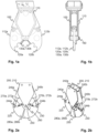
- One such speciality tool is the concrete demolition shears 100 according to fig. 1a-1b , which can be detachably attached to a utility machine, for example an excavator, and which can be moved and aligned with the aid of a utility machine.
- Jaws 112a, 112b have been connected to the frame 110 of the concrete shears 100, which jaws comprise subsequent blades 120a, 120b meant for crushing concrete and blades 130a, 130b meant for cutting metal, which move with the same center point in relation to a central axis 160. This means that concrete to be demolished ends up between the metal cutting blades 130a, 130b, which dulls the blades.
- the opening directions of the jaws 112a, 112b are downwards or nearly straight downwards, which makes it difficult to align the concrete shears 100 with an excavator.
- the excavator When demolishing an edge beam of a bridge, due to the straight downwards opening jaws 112a, 112b, the excavator must work with its boom extended, whereby the center of gravity of the excavator moves closer to the equilibrium point. Having the centrer of gravity move close to the equilibrium point and working at the maximum reach of the machine slows down the work and makes it harder to control the movements. Additionally, the working area of a stationary excavator becomes smaller.
- One object of the invention is to eliminate the above-mentioned problems of currently used concrete shears meant for demolishing reinforced concrete.
- a demolition device for demolishing a concrete structure has a crushing blade for crushing concrete, a cutting blade for cutting metal or a pulverizing blade for grinding concrete, and a combination blade.
- the device can be attached to the utility machine in a detachable manner.
- the crushing and cutting/pulverizing blade are separate blades from each other.
- the combination blade is fitted to be used for crushing concrete with the crushing blade.
- the combination blade is fitted to be used for cutting metal with the cutting blade or for grinding concrete with the pulverizing blade.
- the combination blade has abutment surface parts for the crushing and cutting/pulverizing blade.
- the abutment surface part of the cutting/pulverizing blade makes possible a power transmission between the cutting/pulverizing and combination blade when using a combination blade for crushing concrete.
- the abutment surface part of the crushing blade makes possible a power transmission between the crushing and combination blade when using a combination blade for cutting metal and grinding concrete.
- a utility machine comprises the demolition device, which is in accordance with the previous device embodiment.
- Fig. 1a-1b are described in connection with the background of the invention.
- Fig. 2a-2b show straight from the side and diagonally from the side a demolition device 200 for demolishing a concrete structure, for example reinforced concrete, which demolition device can be attached to a utility machine, for example an excavator, in a detachable manner.
- a demolition device 200 for demolishing a concrete structure for example reinforced concrete
- which demolition device can be attached to a utility machine, for example an excavator, in a detachable manner.
- the device 200 comprises a separate crushing blade (crushing jaw) 220 meant for breaking and/or crushing concrete, which is equipped with a tooth 280a meant for breaking concrete, and a separate cutting blade (cutting jaw) 230 meant for cutting metal.
- the device further has as a third separate blade a combination blade (combination jaw) 250, which is equipped with a tooth 280b corresponding to tooth 280a.
- the combination blade 250 is used for breaking and/or crushing concrete together with a crushing blade 220 and/or for cutting metal together with a cutting blade 230.
- the device 200 comprises moving means 240a, 240b connected to the frame 210 by means of axes 242a, 242b, for example hydraulic or pneumatic cylinders, or hydraulic or electromechanical linear moving units (motors), which are connected by means of axes 244a, 244b in their ends to the crushing and cutting blades 220, 230.
- the means 240a, 240b, to which the utility machine user gives for example electronically or hydraulically transmittable control commands from the utility machine's cab, are fitted to move the crushing, cutting and combination blades 220, 230, 250 around the central axis 260 belonging to the frame 210.
- the device 200 meant for demolishing concrete attached to which has crushing, cutting and combination blades 220, 230, 250 fitted to move around the same center axis.
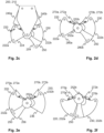
- Fig. 2c-2d and 2e-2f show from the side how the combination blade 250 of the device 200 is utilized both in crushing concrete and cutting metal.
- Fig. 2c shows how the crushing blade 220 forms a first crushing jaw 222a, and the combination blade 250, which is attached in connection with the cutting blade 230, and the cutting blade 230 together form a second crushing jaw 222b.
- crushing jaws 222a, 222b When in accordance to fig. 2c open crushing jaws 222a, 222b are pressed together with means 240a, 240b, for example to crush a piece of concrete between the jaws 222a, 222b, the jaws 222a, 222b turn towards each other in relation to the axis 260 and simultaneously break the piece of concrete with their teeth 280a, 280b and the edges 224, 254 meant for crushing concrete, i.e. the actual blade parts.
- the pressing can be realized by giving the cylinders 240a, 240b a control command, with which they perform the positive movement.
- the jaws turn away from each other in relation to the axis 260. This can be realized by giving the cylinders 240a, 240b a control command, with which they perform the negative movement.
- the movement paths of the the crushing blade 220 and the cutting blade 230 in relation to the center axis 260 are fitted to run so that when pushing, i.e. pressing, the jaws 222a, 222b, the crushing and cutting blades 220, 230 move in opposite directions toward each other on the same path and the movement path of the combination blade 250 is fitted to run in the same direction as the cutting blade 230, but in an interlocking manner in relation to both the crushing blade 220 and the cutting blade 230 (so-called "cross bite").
- This increases the efficiency of the press compared to jaws according to e.g. fig. 1a-1b , which just come straight toward each other.
- the device 200 meant for demolishing concrete attached to which has crushing and cutting blades 220, 230, the movement paths of which are fitted to run towards each other in opposite directions. Additionally, the movement path of the combination blade 250 is fitted to run in an interlocking manner in relation to the movement paths of the crushing and cutting blades 220, 230.
- Fig. 2d the frame 210 has been left out, whereby the moving and locking means 252a, 252b, 270a, 270b, 272a, 272b of the combination blade 250 belonging to the device 200 are better visible, which means are fitted to move the combination blade 250 and lock it in connection with the cutting blade 230, whereby it is possible to crush concrete with the crushing and combination blades 220, 250, i.e. the jaws 222a, 222b.
- the means 252a, 252b, 270a, 270b, 272a, 272b comprise locking slots 252a, 252b in the combination blade 250, a first hydraulic or pneumatic cylinder 270a equipped with a cross-directional locking peg 272a connected to the crushing blade 220 and a second hydraulic or pneumatic cylinder 270b equipped with a cross-directional locking peg 272b easily seen in fig. 2b connected to the cutting blade 230.
- the cylinders 270a, 270b can be realized also with hydraulic or electromechanical linear moving units.
- the cylinders 270a, 270b are cross-linked, so when the cylinder 270a makes a negative movement, i.e. the piston of the cylinder 270a pushes into it, then the cylinder 270b thus makes a positive movement, i.e. the piston of the cylinder 270b pushes out of the cylinder, and vice versa.
- the cylinder 270b When locking the combination blade 250 to the cutting blade 230 to form jaws 222a, 222b, the cylinder 270b is guided to make a positive movement, whereby the piston of the cylinder 270b pushes out and simultaneously pushes the locking peg 272b in the end of the cylinder 270b piston into the corner of the slot 252b of the combination blade 250, turning the combination blade 250 to attach to the cutting blade 230 in an interlocking manner and locking them together in a detachable manner, whereby a jaw 222b is formed and the crushing blade 220 which remains separate forms a jaw 222a in accordance with fig. 2d .
- the combination blade 250 is detached from the cutting blade 230 correspondingly by guiding the cylinder 270b to make a negative movement, whereby its piston pushes back into the cylinder 270b and simultaneously lifts the locking peg 272b in the end of the piston out of the slot 252b, whereby the combination blade 250 detaches from the crushing blade 230.
- Fig. 2e shows how the crushing blade 220 and the thereto attached combination blade 250 form a first cutting jaw 232a and the cutting blade 230 forms a second cutting jaw 232b for cutting and/or breaking metal.
- the device 200 meant for demolishing concrete attached to which additionally has moving and locking means 252a, 252b, 270a, 270b, 272a, 272b, which are fitted to move the combination blade 250 and lock it in connection with the cutting blade 230, whereby it is possible to crush concrete with the crushing and combination blade 220, 250, i.e. the jaws 222a, 222b. Additionally, they are fitted to move the combination blade 250 and lock it in connection with the crushing blade 220, whereby it is possible to cut metal with the cutting and combination blades 230, 250, i.e. the jaws 232a, 232b.
- FIG. 2f shows when the blades 220, 230 are pressed against each other and an unattached combination blade 250 is "loose” between them, but if it is desired to open the pressed-together jaws 232a, 232b with the means 240a, 240b, they turn away from each other in relation to the axis 260.
- Fig. 2e-2f shows means 252a, 252b, 270a, 270b, 272a, 272b, which are fitted to move the combination blade 250 and lock it in connection with the crushing blade 220, whereby it is possible to cut metal with the cutting and combination blades 230, 250, i.e. the jaws 232a, 232b.
- the piston of the cylinder 270a pushes out and simultaneously pushes the locking peg 272a in the end of the cylinder 270a piston into the corner of the slot 252a of the combination blade 250, turning the combination blade 250 to attach to the crushing blade 220 in an interlocking manner and locking them together in a detachable manner, whereby a jaw 232a is formed and the cutting blade 230 which remains separate forms a jaw 232b in accordance with fig. 2e .
- the combination blade 250 is correspondingly detached from the crushing blade 220 by guiding the cylinder 270a to make a negative movement, whereby its piston pushes back into the cylinder 270a and simultaneously lifts the locking peg 272a in the end of the piston out of the slot 252a, whereby the combination blade 250 detaches from the crushing blade 230.
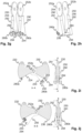
- Fig. 2g-2h show an alternative combination blade 250, which can be used in the device 200 instead of the combination blade 250 presented in connection with the preceding figures.
- the combination blade 250 is to its shape a U profile 290, which is formed of two blade parts 291, 292 and between them of an abutment surface part 293 for the crushing blade 220 and an abutment surface part 294 for the cutting blade 230, which can be attached in a detachable manner and which combine the blade parts 291, 292.
- Both blade parts 291, 292 comprise an edge 254 equipped with a tooth 280b used for crushing and an edge 256 used for cutting.
- the abutment surface 293 makes possible a power transmission between the crushing and combination blade 220, 250 when using a combination blade 250 attached to a crushing blade 220 for cutting metal together with a cutting blade 230.
- the abutment surface 294 makes possible a power transmission between the cutting and combination blade 230, 250 when using a combination blade 250 attached to a cutting blade 230 for crushing concrete together with a crushing blade 220.
- the abutment surfaces 293, 294 are situated at a distance from the axis 260 of the crushing and cutting blades 220, 230, so that the cutting forces caused by the transferred power remain small.
- the power needed for the demolition is transferred to the combination blade 250 with a structure close to the axis 260, a large cutting force forms in the used support structure, which requires a massive support structure in order to endure. Additionally, the structure of the combination blade 250 must be capable of transferring power caused by the demolition work from its tip to the support structure near the axis 260, which also requires a massive and heavy combination blade 250, which is not advantageous in demolition devices.
- Fig. 2i shows how in the device's 200 concrete crushing position the abutment surface 294 is supported against the edge 236 of the cutting blade 230.
- the combination blade 250 attaches to the cutting blade 230 with locking means 252a, 252b, 270a, 270b, 272a, 272b when locking so that the cutting blade 230 pushes into the U profile 290 formed by the blade parts 291, 292 and the abutment surfaces 293, 294 against the abutment surface 294.
- the crushing blade 220 and its edge 224 can push into the U profile 290 all the way to the abutment surface 293, when the crushing blade 220 and the blades 250, 220 attached together are pressed together.
- the movement path of the crushing blade 220 is fitted to run toward (against) the cutting blade 230 and the movement path of the combination blade 250 is fitted to run so that its blade parts 291, 292 interlock in relation to the cutting blade 230 and the abutment surfaces in turn go towards the cutting blade 230.
- Fig. 2j shows how in the metal cutting position, the abutment surface 293 in turn is supported against the edge 224 of the crushing blade 220.
- the combination blade 250 attaches to the crushing blade 220 when locking so that the crushing blade 220 pushes into the U profile 290 against the abutment surface 294.
- the cutting blade (further processing blade) 230 and its edge 236 can push into the U profile 290 all the way against the abutment surface 294, when the blades 220, 250 attached together and the cutting blade 230 are pressed together.
- the movement path of the cutting blade 220 can in turn be toward the crushing blade 220 and the movement path of the combination blade 250 is also such that the blade parts 291, 292 interlock in relation to the crushing blade 220 and the abutment surfaces in turn go toward the crushing blade 220.
- the crushing and cutting blade 220, 230 can as opposed to the figures be fixed, i.e. a part of the frame 210 of the device 200, so that the fixed blade is not set on an axis and does not move in relation to the frame 210.
- the fixed blade can for example be the cutting blade 230.
- the power of the device 200 is produced to the moving blade and the possibly thereto attached combination blade with the aid of a moving means 240a, for example a hydraulic cylinder.
- the crushing and cutting blades 220, 230 can be realized so that they move around separate axes and the combination blade 250 can be without an axis, attaching to the crushing or cutting blade 220, 230.
- a cutting blade 230 can instead of a cutting blade 230 be a pulverizing blade (further processing blade) meant for grinding concrete, whereby it can be used for grinding (pulverizing) crushed concrete in addition to crushing concrete.
- a device 200 equipped with a pulverizing blade is otherwise the same as the device 200 shown in the preceding figures, but it has a pulverizing blade in the jaw 222b, the structure of the edge meant for pulverizing of which differs from the edge 236 of the metal blade 230, and in the same way in the combination blade 250 the structure of the edge meant for pulverizing differs from the edge 256 meant for cutting metal.
- the device 200 makes possible the cutting of metal and crushing of concrete efficiently without changing jaws or concrete to be demolished ending up in the blades meant for cutting metal.
- the device 200 is well suited for example for demolishing edge beams of bridges and for demolishing other corresponding structures below an excavator.
- the working area of an excavator grows without moving the excavator and at the same time it can be used for cutting reinforcement steel, railings built of quite large steel profiles and for crushing concrete. Additionally, the balance and manoeuvrability of the excavator are improved, because the excavator can work with a shorter boom, whereto the device 200 is attached in a detachable manner.
- the utility machine to which the device 200 meant for demolishing a concrete structure, for example reinforced concrete, can be attached in a detachable manner, can be an excavator, which can be a rotating excavator set on a wheel or tracked chassis, a backhoe loader or a mini excavator.
- the utility machine can have a boom, in the end of which there are attaching means and control connecting means, to which the device 200 can be attached in a detachable manner by means of attaching and connecting means in its frame 210.
- the device 200 can be connected to for example the electric or hydraulic system of the utility machine, so that the device 200 and the operation of its moving means 240a, 240b can be controlled from the utility machine.
- the attached and connected device 200 can turn and rotate at the end of the boom of the utility machine, and it can be guided to perform for example one of the following procedures: a pressing movement, an opening movement, a blade transfer, a blade attachment and a blade detachment.
Landscapes
- Engineering & Computer Science (AREA)
- Mechanical Engineering (AREA)
- Architecture (AREA)
- Structural Engineering (AREA)
- Civil Engineering (AREA)
- General Engineering & Computer Science (AREA)
- Mining & Mineral Resources (AREA)
- Food Science & Technology (AREA)
- Chemical & Material Sciences (AREA)
- Chemical Kinetics & Catalysis (AREA)
- Electrochemistry (AREA)
- Working Measures On Existing Buildindgs (AREA)
- Crushing And Grinding (AREA)
Applications Claiming Priority (2)
| Application Number | Priority Date | Filing Date | Title |
|---|---|---|---|
| FI20165900A FI127105B (fi) | 2016-11-25 | 2016-11-25 | Purkulaite ja työkone betonirakenteen purkamiseksi |
| PCT/FI2017/050821 WO2018096220A1 (en) | 2016-11-25 | 2017-11-24 | Demolition device and utility machine for demolishing a concrete structure |
Publications (3)
| Publication Number | Publication Date |
|---|---|
| EP3545137A1 EP3545137A1 (en) | 2019-10-02 |
| EP3545137A4 EP3545137A4 (en) | 2020-06-03 |
| EP3545137B1 true EP3545137B1 (en) | 2024-02-21 |
Family
ID=60269555
Family Applications (1)
| Application Number | Title | Priority Date | Filing Date |
|---|---|---|---|
| EP17874066.8A Active EP3545137B1 (en) | 2016-11-25 | 2017-11-24 | Demolition device and utility machine for demolishing a concrete structure |
Country Status (7)
| Country | Link |
|---|---|
| US (1) | US11638921B2 (pl) |
| EP (1) | EP3545137B1 (pl) |
| DK (1) | DK3545137T3 (pl) |
| ES (1) | ES2988788T3 (pl) |
| FI (1) | FI127105B (pl) |
| PL (1) | PL3545137T3 (pl) |
| WO (1) | WO2018096220A1 (pl) |
Families Citing this family (2)
| Publication number | Priority date | Publication date | Assignee | Title |
|---|---|---|---|---|
| FI130556B (fi) * | 2017-02-28 | 2023-11-17 | Savonlinnan Pr Urakointi Oy | Kaksitoiminen purkulaite ja työkone rakenteiden purkamiseksi |
| DE102023116503A1 (de) * | 2023-06-22 | 2024-12-24 | Max Wild Gmbh | Werkzeug zum Verarbeiten von armiertem Beton |
Family Cites Families (11)
| Publication number | Priority date | Publication date | Assignee | Title |
|---|---|---|---|---|
| US4519135A (en) * | 1982-09-13 | 1985-05-28 | Labounty Roy E | Metal demolition shear |
| FR2637303B1 (fr) | 1988-09-30 | 1990-12-14 | Ameca Sa | Pince brise-beton |
| DE9210292U1 (de) * | 1992-07-31 | 1992-10-22 | Mieger, Rolf, 7951 Kirchdorf | Werkzeug für Arbeitsmaschinen |
| AT403491B (de) * | 1996-02-15 | 1998-02-25 | Wimmer Alois Ing | Betonbrechzange mit schneidschere |
| JP3173656B2 (ja) * | 1999-04-28 | 2001-06-04 | 優 岡崎 | 構造物用破砕機 |
| JP3553514B2 (ja) * | 2001-03-12 | 2004-08-11 | 優 岡崎 | 廃材用切断装置 |
| AU2003258897B2 (en) * | 2002-08-06 | 2008-04-10 | Simon Robert Ward | Cutting implement |
| EP2801671B1 (en) * | 2012-06-07 | 2018-09-05 | Caterpillar Work Tools B. V. | A jaw assembly for a demolition tool |
| EP3149248B1 (en) * | 2014-05-27 | 2020-07-01 | Savonlinnan Pr-urakointi OY | Apparatus for pulling a concrete structure down |
| CN104972477B (zh) * | 2015-07-21 | 2017-02-01 | 北京工业大学 | 一种六杆机构的多功能工程属具 |
| FI130556B (fi) * | 2017-02-28 | 2023-11-17 | Savonlinnan Pr Urakointi Oy | Kaksitoiminen purkulaite ja työkone rakenteiden purkamiseksi |
-
2016
- 2016-11-25 FI FI20165900A patent/FI127105B/fi active IP Right Grant
-
2017
- 2017-11-24 US US16/463,899 patent/US11638921B2/en active Active
- 2017-11-24 ES ES17874066T patent/ES2988788T3/es active Active
- 2017-11-24 WO PCT/FI2017/050821 patent/WO2018096220A1/en not_active Ceased
- 2017-11-24 EP EP17874066.8A patent/EP3545137B1/en active Active
- 2017-11-24 PL PL17874066.8T patent/PL3545137T3/pl unknown
- 2017-11-24 DK DK17874066.8T patent/DK3545137T3/da active
Also Published As
| Publication number | Publication date |
|---|---|
| EP3545137A1 (en) | 2019-10-02 |
| EP3545137A4 (en) | 2020-06-03 |
| FI20165900A7 (fi) | 2017-11-15 |
| FI127105B (fi) | 2017-11-15 |
| ES2988788T3 (es) | 2024-11-21 |
| PL3545137T3 (pl) | 2024-06-24 |
| US20190283033A1 (en) | 2019-09-19 |
| WO2018096220A1 (en) | 2018-05-31 |
| DK3545137T3 (en) | 2024-05-27 |
| US11638921B2 (en) | 2023-05-02 |
Similar Documents
| Publication | Publication Date | Title |
|---|---|---|
| US4951886A (en) | Concrete crusher | |
| US5183216A (en) | Demolishing apparatus | |
| EP1218600B1 (en) | Cutting or crushing apparatus | |
| CA2096450C (en) | Tool for implements | |
| US7306177B2 (en) | Cutting or crushing implement | |
| EP3545137B1 (en) | Demolition device and utility machine for demolishing a concrete structure | |
| JP4546832B2 (ja) | 一つのあごセットの複数のツールのアタッチメント装置 | |
| EP3121340B1 (en) | Replaceable tip for a demolition tool | |
| CA2875260A1 (en) | Interlocking tip for demolition and construction equipment | |
| EP2001627B1 (de) | Abbruchzange | |
| US20090145274A1 (en) | Demolition shears | |
| EP3589789B1 (en) | Double acting demolition device and utility machine for demolishing structures | |
| KR101816455B1 (ko) | 다기능 어태치먼트 및 이를 포함하는 건설장비 | |
| EP3149248B1 (en) | Apparatus for pulling a concrete structure down | |
| KR101816456B1 (ko) | 다기능 어태치먼트 및 이를 포함하는 건설장비 | |
| JP2010133109A (ja) | 破砕機及びこの破砕機を備えた建設機械 | |
| FI125691B (fi) | Laite ja työkone betonirakenteen purkamiseksi | |
| KR200267832Y1 (ko) | 굴착기의 선단장치 | |
| JP3174918U (ja) | 切断・挟持併用解体機 | |
| US9044815B2 (en) | Keyless coupling arrangement | |
| CN218611472U (zh) | 一种应用于建筑体钢筋头的切断器 | |
| DE20218497U1 (de) | Hydraulikanbaugerät | |
| EP2963189A1 (en) | Work tool and method for operating the work tool | |
| NZ538103A (en) | A cutting implement | |
| UA119730U (uk) | Гідроножиці інтенсивної дії |
Legal Events
| Date | Code | Title | Description |
|---|---|---|---|
| STAA | Information on the status of an ep patent application or granted ep patent |
Free format text: STATUS: THE INTERNATIONAL PUBLICATION HAS BEEN MADE |
|
| PUAI | Public reference made under article 153(3) epc to a published international application that has entered the european phase |
Free format text: ORIGINAL CODE: 0009012 |
|
| STAA | Information on the status of an ep patent application or granted ep patent |
Free format text: STATUS: REQUEST FOR EXAMINATION WAS MADE |
|
| 17P | Request for examination filed |
Effective date: 20190624 |
|
| AK | Designated contracting states |
Kind code of ref document: A1 Designated state(s): AL AT BE BG CH CY CZ DE DK EE ES FI FR GB GR HR HU IE IS IT LI LT LU LV MC MK MT NL NO PL PT RO RS SE SI SK SM TR |
|
| AX | Request for extension of the european patent |
Extension state: BA ME |
|
| DAV | Request for validation of the european patent (deleted) | ||
| DAX | Request for extension of the european patent (deleted) | ||
| A4 | Supplementary search report drawn up and despatched |
Effective date: 20200507 |
|
| RIC1 | Information provided on ipc code assigned before grant |
Ipc: E02F 3/96 20060101AFI20200429BHEP Ipc: E04G 23/08 20060101ALI20200429BHEP Ipc: B02C 1/10 20060101ALI20200429BHEP Ipc: B23D 17/00 20060101ALI20200429BHEP Ipc: B23D 35/00 20060101ALI20200429BHEP Ipc: E02F 9/28 20060101ALI20200429BHEP |
|
| STAA | Information on the status of an ep patent application or granted ep patent |
Free format text: STATUS: EXAMINATION IS IN PROGRESS |
|
| 17Q | First examination report despatched |
Effective date: 20210713 |
|
| GRAP | Despatch of communication of intention to grant a patent |
Free format text: ORIGINAL CODE: EPIDOSNIGR1 |
|
| STAA | Information on the status of an ep patent application or granted ep patent |
Free format text: STATUS: GRANT OF PATENT IS INTENDED |
|
| INTG | Intention to grant announced |
Effective date: 20231018 |
|
| GRAS | Grant fee paid |
Free format text: ORIGINAL CODE: EPIDOSNIGR3 |
|
| GRAA | (expected) grant |
Free format text: ORIGINAL CODE: 0009210 |
|
| STAA | Information on the status of an ep patent application or granted ep patent |
Free format text: STATUS: THE PATENT HAS BEEN GRANTED |
|
| AK | Designated contracting states |
Kind code of ref document: B1 Designated state(s): AL AT BE BG CH CY CZ DE DK EE ES FI FR GB GR HR HU IE IS IT LI LT LU LV MC MK MT NL NO PL PT RO RS SE SI SK SM TR |
|
| REG | Reference to a national code |
Ref country code: GB Ref legal event code: FG4D |
|
| REG | Reference to a national code |
Ref country code: CH Ref legal event code: EP |
|
| REG | Reference to a national code |
Ref country code: IE Ref legal event code: FG4D |
|
| REG | Reference to a national code |
Ref country code: DE Ref legal event code: R096 Ref document number: 602017079427 Country of ref document: DE |
|
| REG | Reference to a national code |
Ref country code: SE Ref legal event code: TRGR |
|
| REG | Reference to a national code |
Ref country code: DK Ref legal event code: T3 Effective date: 20240522 |
|
| REG | Reference to a national code |
Ref country code: LT Ref legal event code: MG9D |
|
| REG | Reference to a national code |
Ref country code: NL Ref legal event code: FP |
|
| PG25 | Lapsed in a contracting state [announced via postgrant information from national office to epo] |
Ref country code: IS Free format text: LAPSE BECAUSE OF FAILURE TO SUBMIT A TRANSLATION OF THE DESCRIPTION OR TO PAY THE FEE WITHIN THE PRESCRIBED TIME-LIMIT Effective date: 20240621 |
|
| PG25 | Lapsed in a contracting state [announced via postgrant information from national office to epo] |
Ref country code: LT Free format text: LAPSE BECAUSE OF FAILURE TO SUBMIT A TRANSLATION OF THE DESCRIPTION OR TO PAY THE FEE WITHIN THE PRESCRIBED TIME-LIMIT Effective date: 20240221 |
|
| PG25 | Lapsed in a contracting state [announced via postgrant information from national office to epo] |
Ref country code: GR Free format text: LAPSE BECAUSE OF FAILURE TO SUBMIT A TRANSLATION OF THE DESCRIPTION OR TO PAY THE FEE WITHIN THE PRESCRIBED TIME-LIMIT Effective date: 20240522 |
|
| PG25 | Lapsed in a contracting state [announced via postgrant information from national office to epo] |
Ref country code: RS Free format text: LAPSE BECAUSE OF FAILURE TO SUBMIT A TRANSLATION OF THE DESCRIPTION OR TO PAY THE FEE WITHIN THE PRESCRIBED TIME-LIMIT Effective date: 20240521 Ref country code: HR Free format text: LAPSE BECAUSE OF FAILURE TO SUBMIT A TRANSLATION OF THE DESCRIPTION OR TO PAY THE FEE WITHIN THE PRESCRIBED TIME-LIMIT Effective date: 20240221 |
|
| PG25 | Lapsed in a contracting state [announced via postgrant information from national office to epo] |
Ref country code: RS Free format text: LAPSE BECAUSE OF FAILURE TO SUBMIT A TRANSLATION OF THE DESCRIPTION OR TO PAY THE FEE WITHIN THE PRESCRIBED TIME-LIMIT Effective date: 20240521 Ref country code: NO Free format text: LAPSE BECAUSE OF FAILURE TO SUBMIT A TRANSLATION OF THE DESCRIPTION OR TO PAY THE FEE WITHIN THE PRESCRIBED TIME-LIMIT Effective date: 20240521 Ref country code: LT Free format text: LAPSE BECAUSE OF FAILURE TO SUBMIT A TRANSLATION OF THE DESCRIPTION OR TO PAY THE FEE WITHIN THE PRESCRIBED TIME-LIMIT Effective date: 20240221 Ref country code: IS Free format text: LAPSE BECAUSE OF FAILURE TO SUBMIT A TRANSLATION OF THE DESCRIPTION OR TO PAY THE FEE WITHIN THE PRESCRIBED TIME-LIMIT Effective date: 20240621 Ref country code: HR Free format text: LAPSE BECAUSE OF FAILURE TO SUBMIT A TRANSLATION OF THE DESCRIPTION OR TO PAY THE FEE WITHIN THE PRESCRIBED TIME-LIMIT Effective date: 20240221 Ref country code: GR Free format text: LAPSE BECAUSE OF FAILURE TO SUBMIT A TRANSLATION OF THE DESCRIPTION OR TO PAY THE FEE WITHIN THE PRESCRIBED TIME-LIMIT Effective date: 20240522 Ref country code: FI Free format text: LAPSE BECAUSE OF FAILURE TO SUBMIT A TRANSLATION OF THE DESCRIPTION OR TO PAY THE FEE WITHIN THE PRESCRIBED TIME-LIMIT Effective date: 20240221 Ref country code: BG Free format text: LAPSE BECAUSE OF FAILURE TO SUBMIT A TRANSLATION OF THE DESCRIPTION OR TO PAY THE FEE WITHIN THE PRESCRIBED TIME-LIMIT Effective date: 20240221 |
|
| PG25 | Lapsed in a contracting state [announced via postgrant information from national office to epo] |
Ref country code: PT Free format text: LAPSE BECAUSE OF FAILURE TO SUBMIT A TRANSLATION OF THE DESCRIPTION OR TO PAY THE FEE WITHIN THE PRESCRIBED TIME-LIMIT Effective date: 20240621 |
|
| PG25 | Lapsed in a contracting state [announced via postgrant information from national office to epo] |
Ref country code: PT Free format text: LAPSE BECAUSE OF FAILURE TO SUBMIT A TRANSLATION OF THE DESCRIPTION OR TO PAY THE FEE WITHIN THE PRESCRIBED TIME-LIMIT Effective date: 20240621 Ref country code: LV Free format text: LAPSE BECAUSE OF FAILURE TO SUBMIT A TRANSLATION OF THE DESCRIPTION OR TO PAY THE FEE WITHIN THE PRESCRIBED TIME-LIMIT Effective date: 20240221 |
|
| PG25 | Lapsed in a contracting state [announced via postgrant information from national office to epo] |
Ref country code: SM Free format text: LAPSE BECAUSE OF FAILURE TO SUBMIT A TRANSLATION OF THE DESCRIPTION OR TO PAY THE FEE WITHIN THE PRESCRIBED TIME-LIMIT Effective date: 20240221 |
|
| REG | Reference to a national code |
Ref country code: AT Ref legal event code: UEP Ref document number: 1659232 Country of ref document: AT Kind code of ref document: T Effective date: 20240221 |
|
| PG25 | Lapsed in a contracting state [announced via postgrant information from national office to epo] |
Ref country code: CZ Free format text: LAPSE BECAUSE OF FAILURE TO SUBMIT A TRANSLATION OF THE DESCRIPTION OR TO PAY THE FEE WITHIN THE PRESCRIBED TIME-LIMIT Effective date: 20240221 Ref country code: EE Free format text: LAPSE BECAUSE OF FAILURE TO SUBMIT A TRANSLATION OF THE DESCRIPTION OR TO PAY THE FEE WITHIN THE PRESCRIBED TIME-LIMIT Effective date: 20240221 |
|
| PG25 | Lapsed in a contracting state [announced via postgrant information from national office to epo] |
Ref country code: SK Free format text: LAPSE BECAUSE OF FAILURE TO SUBMIT A TRANSLATION OF THE DESCRIPTION OR TO PAY THE FEE WITHIN THE PRESCRIBED TIME-LIMIT Effective date: 20240221 |
|
| PG25 | Lapsed in a contracting state [announced via postgrant information from national office to epo] |
Ref country code: SM Free format text: LAPSE BECAUSE OF FAILURE TO SUBMIT A TRANSLATION OF THE DESCRIPTION OR TO PAY THE FEE WITHIN THE PRESCRIBED TIME-LIMIT Effective date: 20240221 Ref country code: SK Free format text: LAPSE BECAUSE OF FAILURE TO SUBMIT A TRANSLATION OF THE DESCRIPTION OR TO PAY THE FEE WITHIN THE PRESCRIBED TIME-LIMIT Effective date: 20240221 Ref country code: RO Free format text: LAPSE BECAUSE OF FAILURE TO SUBMIT A TRANSLATION OF THE DESCRIPTION OR TO PAY THE FEE WITHIN THE PRESCRIBED TIME-LIMIT Effective date: 20240221 Ref country code: EE Free format text: LAPSE BECAUSE OF FAILURE TO SUBMIT A TRANSLATION OF THE DESCRIPTION OR TO PAY THE FEE WITHIN THE PRESCRIBED TIME-LIMIT Effective date: 20240221 Ref country code: CZ Free format text: LAPSE BECAUSE OF FAILURE TO SUBMIT A TRANSLATION OF THE DESCRIPTION OR TO PAY THE FEE WITHIN THE PRESCRIBED TIME-LIMIT Effective date: 20240221 |
|
| REG | Reference to a national code |
Ref country code: ES Ref legal event code: FG2A Ref document number: 2988788 Country of ref document: ES Kind code of ref document: T3 Effective date: 20241121 |
|
| REG | Reference to a national code |
Ref country code: DE Ref legal event code: R097 Ref document number: 602017079427 Country of ref document: DE |
|
| PLBE | No opposition filed within time limit |
Free format text: ORIGINAL CODE: 0009261 |
|
| STAA | Information on the status of an ep patent application or granted ep patent |
Free format text: STATUS: NO OPPOSITION FILED WITHIN TIME LIMIT |
|
| 26N | No opposition filed |
Effective date: 20241122 |
|
| PG25 | Lapsed in a contracting state [announced via postgrant information from national office to epo] |
Ref country code: SI Free format text: LAPSE BECAUSE OF FAILURE TO SUBMIT A TRANSLATION OF THE DESCRIPTION OR TO PAY THE FEE WITHIN THE PRESCRIBED TIME-LIMIT Effective date: 20240221 |
|
| REG | Reference to a national code |
Ref country code: CH Ref legal event code: PL |
|
| PG25 | Lapsed in a contracting state [announced via postgrant information from national office to epo] |
Ref country code: MC Free format text: LAPSE BECAUSE OF FAILURE TO SUBMIT A TRANSLATION OF THE DESCRIPTION OR TO PAY THE FEE WITHIN THE PRESCRIBED TIME-LIMIT Effective date: 20240221 |
|
| PG25 | Lapsed in a contracting state [announced via postgrant information from national office to epo] |
Ref country code: LU Free format text: LAPSE BECAUSE OF NON-PAYMENT OF DUE FEES Effective date: 20241124 |
|
| REG | Reference to a national code |
Ref country code: CH Ref legal event code: PL |
|
| GBPC | Gb: european patent ceased through non-payment of renewal fee |
Effective date: 20241124 |
|
| PG25 | Lapsed in a contracting state [announced via postgrant information from national office to epo] |
Ref country code: CH Free format text: LAPSE BECAUSE OF NON-PAYMENT OF DUE FEES Effective date: 20241130 |
|
| PG25 | Lapsed in a contracting state [announced via postgrant information from national office to epo] |
Ref country code: GB Free format text: LAPSE BECAUSE OF NON-PAYMENT OF DUE FEES Effective date: 20241124 |
|
| PG25 | Lapsed in a contracting state [announced via postgrant information from national office to epo] |
Ref country code: IE Free format text: LAPSE BECAUSE OF NON-PAYMENT OF DUE FEES Effective date: 20241124 |
|
| PGFP | Annual fee paid to national office [announced via postgrant information from national office to epo] |
Ref country code: NL Payment date: 20251121 Year of fee payment: 9 |
|
| PGFP | Annual fee paid to national office [announced via postgrant information from national office to epo] |
Ref country code: DE Payment date: 20251118 Year of fee payment: 9 |
|
| PGFP | Annual fee paid to national office [announced via postgrant information from national office to epo] |
Ref country code: AT Payment date: 20251118 Year of fee payment: 9 |
|
| PGFP | Annual fee paid to national office [announced via postgrant information from national office to epo] |
Ref country code: IT Payment date: 20251121 Year of fee payment: 9 Ref country code: DK Payment date: 20251120 Year of fee payment: 9 |
|
| PGFP | Annual fee paid to national office [announced via postgrant information from national office to epo] |
Ref country code: FR Payment date: 20251117 Year of fee payment: 9 |
|
| PGFP | Annual fee paid to national office [announced via postgrant information from national office to epo] |
Ref country code: BE Payment date: 20251121 Year of fee payment: 9 |
|
| PGFP | Annual fee paid to national office [announced via postgrant information from national office to epo] |
Ref country code: SE Payment date: 20251121 Year of fee payment: 9 |
|
| PGFP | Annual fee paid to national office [announced via postgrant information from national office to epo] |
Ref country code: PL Payment date: 20251024 Year of fee payment: 9 |
|
| PGFP | Annual fee paid to national office [announced via postgrant information from national office to epo] |
Ref country code: ES Payment date: 20251208 Year of fee payment: 9 |
|
| PG25 | Lapsed in a contracting state [announced via postgrant information from national office to epo] |
Ref country code: HU Free format text: LAPSE BECAUSE OF FAILURE TO SUBMIT A TRANSLATION OF THE DESCRIPTION OR TO PAY THE FEE WITHIN THE PRESCRIBED TIME-LIMIT; INVALID AB INITIO Effective date: 20171124 |