EP3543793A1 - Image forming apparatus and cartridge - Google Patents
Image forming apparatus and cartridge Download PDFInfo
- Publication number
- EP3543793A1 EP3543793A1 EP18209121.5A EP18209121A EP3543793A1 EP 3543793 A1 EP3543793 A1 EP 3543793A1 EP 18209121 A EP18209121 A EP 18209121A EP 3543793 A1 EP3543793 A1 EP 3543793A1
- Authority
- EP
- European Patent Office
- Prior art keywords
- cartridge
- drive transmission
- transmission member
- image forming
- forming apparatus
- Prior art date
- Legal status (The legal status is an assumption and is not a legal conclusion. Google has not performed a legal analysis and makes no representation as to the accuracy of the status listed.)
- Withdrawn
Links
Images













Classifications
-
- G—PHYSICS
- G03—PHOTOGRAPHY; CINEMATOGRAPHY; ANALOGOUS TECHNIQUES USING WAVES OTHER THAN OPTICAL WAVES; ELECTROGRAPHY; HOLOGRAPHY
- G03G—ELECTROGRAPHY; ELECTROPHOTOGRAPHY; MAGNETOGRAPHY
- G03G21/00—Arrangements not provided for by groups G03G13/00 - G03G19/00, e.g. cleaning, elimination of residual charge
- G03G21/16—Mechanical means for facilitating the maintenance of the apparatus, e.g. modular arrangements
- G03G21/18—Mechanical means for facilitating the maintenance of the apparatus, e.g. modular arrangements using a processing cartridge, whereby the process cartridge comprises at least two image processing means in a single unit
- G03G21/1839—Means for handling the process cartridge in the apparatus body
- G03G21/1857—Means for handling the process cartridge in the apparatus body for transmitting mechanical drive power to the process cartridge, drive mechanisms, gears, couplings, braking mechanisms
-
- G—PHYSICS
- G03—PHOTOGRAPHY; CINEMATOGRAPHY; ANALOGOUS TECHNIQUES USING WAVES OTHER THAN OPTICAL WAVES; ELECTROGRAPHY; HOLOGRAPHY
- G03G—ELECTROGRAPHY; ELECTROPHOTOGRAPHY; MAGNETOGRAPHY
- G03G21/00—Arrangements not provided for by groups G03G13/00 - G03G19/00, e.g. cleaning, elimination of residual charge
- G03G21/16—Mechanical means for facilitating the maintenance of the apparatus, e.g. modular arrangements
- G03G21/18—Mechanical means for facilitating the maintenance of the apparatus, e.g. modular arrangements using a processing cartridge, whereby the process cartridge comprises at least two image processing means in a single unit
- G03G21/1839—Means for handling the process cartridge in the apparatus body
- G03G21/1857—Means for handling the process cartridge in the apparatus body for transmitting mechanical drive power to the process cartridge, drive mechanisms, gears, couplings, braking mechanisms
- G03G21/186—Axial couplings
-
- G—PHYSICS
- G03—PHOTOGRAPHY; CINEMATOGRAPHY; ANALOGOUS TECHNIQUES USING WAVES OTHER THAN OPTICAL WAVES; ELECTROGRAPHY; HOLOGRAPHY
- G03G—ELECTROGRAPHY; ELECTROPHOTOGRAPHY; MAGNETOGRAPHY
- G03G15/00—Apparatus for electrographic processes using a charge pattern
- G03G15/06—Apparatus for electrographic processes using a charge pattern for developing
- G03G15/08—Apparatus for electrographic processes using a charge pattern for developing using a solid developer, e.g. powder developer
- G03G15/0806—Apparatus for electrographic processes using a charge pattern for developing using a solid developer, e.g. powder developer on a donor element, e.g. belt, roller
- G03G15/0818—Apparatus for electrographic processes using a charge pattern for developing using a solid developer, e.g. powder developer on a donor element, e.g. belt, roller characterised by the structure of the donor member, e.g. surface properties
-
- G—PHYSICS
- G03—PHOTOGRAPHY; CINEMATOGRAPHY; ANALOGOUS TECHNIQUES USING WAVES OTHER THAN OPTICAL WAVES; ELECTROGRAPHY; HOLOGRAPHY
- G03G—ELECTROGRAPHY; ELECTROPHOTOGRAPHY; MAGNETOGRAPHY
- G03G21/00—Arrangements not provided for by groups G03G13/00 - G03G19/00, e.g. cleaning, elimination of residual charge
- G03G21/16—Mechanical means for facilitating the maintenance of the apparatus, e.g. modular arrangements
- G03G21/1642—Mechanical means for facilitating the maintenance of the apparatus, e.g. modular arrangements for connecting the different parts of the apparatus
- G03G21/1647—Mechanical connection means
-
- G—PHYSICS
- G03—PHOTOGRAPHY; CINEMATOGRAPHY; ANALOGOUS TECHNIQUES USING WAVES OTHER THAN OPTICAL WAVES; ELECTROGRAPHY; HOLOGRAPHY
- G03G—ELECTROGRAPHY; ELECTROPHOTOGRAPHY; MAGNETOGRAPHY
- G03G21/00—Arrangements not provided for by groups G03G13/00 - G03G19/00, e.g. cleaning, elimination of residual charge
- G03G21/16—Mechanical means for facilitating the maintenance of the apparatus, e.g. modular arrangements
- G03G21/18—Mechanical means for facilitating the maintenance of the apparatus, e.g. modular arrangements using a processing cartridge, whereby the process cartridge comprises at least two image processing means in a single unit
- G03G21/1803—Arrangements or disposition of the complete process cartridge or parts thereof
- G03G21/1814—Details of parts of process cartridge, e.g. for charging, transfer, cleaning, developing
-
- G—PHYSICS
- G03—PHOTOGRAPHY; CINEMATOGRAPHY; ANALOGOUS TECHNIQUES USING WAVES OTHER THAN OPTICAL WAVES; ELECTROGRAPHY; HOLOGRAPHY
- G03G—ELECTROGRAPHY; ELECTROPHOTOGRAPHY; MAGNETOGRAPHY
- G03G21/00—Arrangements not provided for by groups G03G13/00 - G03G19/00, e.g. cleaning, elimination of residual charge
- G03G21/16—Mechanical means for facilitating the maintenance of the apparatus, e.g. modular arrangements
- G03G21/18—Mechanical means for facilitating the maintenance of the apparatus, e.g. modular arrangements using a processing cartridge, whereby the process cartridge comprises at least two image processing means in a single unit
- G03G21/1839—Means for handling the process cartridge in the apparatus body
- G03G21/1842—Means for handling the process cartridge in the apparatus body for guiding and mounting the process cartridge, positioning, alignment, locks
-
- G—PHYSICS
- G03—PHOTOGRAPHY; CINEMATOGRAPHY; ANALOGOUS TECHNIQUES USING WAVES OTHER THAN OPTICAL WAVES; ELECTROGRAPHY; HOLOGRAPHY
- G03G—ELECTROGRAPHY; ELECTROPHOTOGRAPHY; MAGNETOGRAPHY
- G03G21/00—Arrangements not provided for by groups G03G13/00 - G03G19/00, e.g. cleaning, elimination of residual charge
- G03G21/16—Mechanical means for facilitating the maintenance of the apparatus, e.g. modular arrangements
- G03G21/18—Mechanical means for facilitating the maintenance of the apparatus, e.g. modular arrangements using a processing cartridge, whereby the process cartridge comprises at least two image processing means in a single unit
- G03G21/1839—Means for handling the process cartridge in the apparatus body
- G03G21/1857—Means for handling the process cartridge in the apparatus body for transmitting mechanical drive power to the process cartridge, drive mechanisms, gears, couplings, braking mechanisms
- G03G21/1864—Means for handling the process cartridge in the apparatus body for transmitting mechanical drive power to the process cartridge, drive mechanisms, gears, couplings, braking mechanisms associated with a positioning function
-
- G—PHYSICS
- G03—PHOTOGRAPHY; CINEMATOGRAPHY; ANALOGOUS TECHNIQUES USING WAVES OTHER THAN OPTICAL WAVES; ELECTROGRAPHY; HOLOGRAPHY
- G03G—ELECTROGRAPHY; ELECTROPHOTOGRAPHY; MAGNETOGRAPHY
- G03G15/00—Apparatus for electrographic processes using a charge pattern
- G03G15/75—Details relating to xerographic drum, band or plate, e.g. replacing, testing
- G03G15/757—Drive mechanisms for photosensitive medium, e.g. gears
-
- G—PHYSICS
- G03—PHOTOGRAPHY; CINEMATOGRAPHY; ANALOGOUS TECHNIQUES USING WAVES OTHER THAN OPTICAL WAVES; ELECTROGRAPHY; HOLOGRAPHY
- G03G—ELECTROGRAPHY; ELECTROPHOTOGRAPHY; MAGNETOGRAPHY
- G03G21/00—Arrangements not provided for by groups G03G13/00 - G03G19/00, e.g. cleaning, elimination of residual charge
- G03G21/16—Mechanical means for facilitating the maintenance of the apparatus, e.g. modular arrangements
- G03G21/1604—Arrangement or disposition of the entire apparatus
- G03G21/1623—Means to access the interior of the apparatus
- G03G21/1633—Means to access the interior of the apparatus using doors or covers
-
- G—PHYSICS
- G03—PHOTOGRAPHY; CINEMATOGRAPHY; ANALOGOUS TECHNIQUES USING WAVES OTHER THAN OPTICAL WAVES; ELECTROGRAPHY; HOLOGRAPHY
- G03G—ELECTROGRAPHY; ELECTROPHOTOGRAPHY; MAGNETOGRAPHY
- G03G2221/00—Processes not provided for by group G03G2215/00, e.g. cleaning or residual charge elimination
- G03G2221/16—Mechanical means for facilitating the maintenance of the apparatus, e.g. modular arrangements and complete machine concepts
- G03G2221/18—Cartridge systems
- G03G2221/183—Process cartridge
- G03G2221/1853—Process cartridge having a submodular arrangement
- G03G2221/1869—Cartridge holders, e.g. intermediate frames for placing cartridge parts therein
Definitions
- the present invention relates to a cartridge and an image forming apparatus using the cartridge.
- the cartridge is dismountable from a main assembly of the image forming apparatus.
- One example is a process cartridge.
- the process cartridge is a cartridge that is integrated with a photosensitive member and process mans actable on the photosensitive member into a cartridge which is dismountably mountable to a main assembly of an electrophotographic image forming apparatus.
- the photosensitive member and at least one of a developing means, a charging means, and a cleaning means as the above-mentioned process means are integrally assembled into a cartridge.
- An image forming apparatus in the present application is an electrophotographic image forming apparatus for forming an image on a recording medium by using an electrophotographic image forming process.
- Examples of the electrophotographic image forming apparatus include an electrophotographic copying machine, an electrophotographic printer (LED printer, laser beam printer, etc.), a facsimile machine, a word processor, and the like.
- an electrophotographic photosensitive member generally a drum type image bearing member, that is, a photosensitive drum (electrophotographic photosensitive drum) is uniformly charged. Subsequently, the charged photosensitive drum is selectively exposed to form an electrostatic latent image (electrostatic image) on the photosensitive drum. Next, the electrostatic latent image formed on the photosensitive drum is developed into a toner image with toner as developer.
- a toner image formed on the photosensitive drum is transferred onto a recording material such as a recording sheet, a plastic sheet, and further heat and pressure are applied to the toner image transferred onto the recording material, by which the toner image is fixed on the recording material, thus performing image recording operation.
- a recording material such as a recording sheet, a plastic sheet
- Such an image forming apparatus generally requires toner replenishment and maintenance of various process means.
- a process cartridge which is dismountable to a main assembly of the image forming apparatus by integrating the photosensitive drum, the charging means, the developing means, the cleaning means and the like inside the frame into a cartridge is in practical use.
- this process cartridge system According to this process cartridge system, a part of the maintenance of the apparatus can be performed by the user himself/herself without relying on a service person in charge of after-sales service. Therefore, an operability of the apparatus can be remarkably improved, and an image forming apparatus excellent in usability can be provided. Therefore, this process cartridge system is widely used in image forming apparatuses.
- Japanese Patent Application Laid-open No. 8-328449 discloses a drive transmission member for transmitting driving force (drive) from the main assembly of the image forming apparatus to the process cartridge.
- a coupling is provided at a free end of the drive transmission member, and the drive transmission member is urged toward the process cartridge side by a spring.
- the drive transmission member of this image forming apparatus When an opening and closing door of the image forming apparatus main assembly is closed, the drive transmission member of this image forming apparatus is pressed by the spring and moves toward the process cartridge. By doing so, the drive transmission member engages (couples) with the coupling of the process cartridge, and the driving force can be transmitted to the process cartridge.
- the drive transmission member moves in a direction away from the process cartridge against the spring by a cam. By doing so, the engagement (coupling) of the drive transmission member with the coupling of the process cartridge is released, and the process cartridge can be dismounted from the image forming apparatus main assembly.
- a representative structure according to the present application is an image forming apparatus comprising (i) a cartridge; and (ii) a main assembly to which said cartridge is mounted; said main assembly including, (ii-i) a drive output member configured to transmit a driving force to said cartridge, said drive output member being movable between an advanced position advanced toward said cartridge and a retracted position retracted from the advanced position, and (ii-ii) an inclination imparting portion for inclining said drive output member with movement of said drive output member from the advanced position to the retracted position.
- a rotational axis direction of an electrophotographic photosensitive drum is referred to as a longitudinal direction.
- a side on which an electrophotographic photosensitive drum receives the driving force from a main assembly of an image forming apparatus is referred as a driving side, and the opposite side thereof is referred to as a non-driving side.
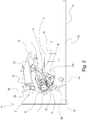
- FIG. 2 is a sectional view of the apparatus main assembly (electrophotographic image forming apparatus main assembly, image forming apparatus main assembly) A and the process cartridge (hereinafter referred to as cartridge B) of the electrophotographic image forming apparatus according to Embodiment 1 of the present invention.
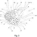
- Figure 3 is a sectional view of the cartridge B.
- the apparatus main assembly A is a part of the electrophotographic image forming apparatus excluding the cartridge B.
- An electrophotographic image forming apparatus (image forming apparatus) shown in Figure 2 is a laser beam printer using an electrophotographic technique in which the cartridge B is dismountably mounted to the apparatus main assembly A.
- An exposure device 3 laser scanner unit
- a sheet tray 4 containing recording materials (hereinafter referred to as sheet materials PA) to be subjected to image formation is provided below the cartridge B.
- the electrophotographic photosensitive drum 62 is a photosensitive member (electrophotographic photosensitive member) for forming an electrophotographic image.
- the fixing device 9 comprises a heating roller 9a and a pressure roller 9b.
- the electrophotographic photosensitive drum (hereinafter referred to as photosensitive drum 62 or simply drum 62) is rotationally driven in the direction of arrow R at a predetermined circumferential speed (process speed).
- the charging roller (charging member) 66 to which the bias voltage is applied contacts with an outer peripheral surface of the drum 62 to uniformly charge the outer peripheral surface of the drum 62.
- An exposure device 3 outputs a laser beam L in accordance with image information.
- the laser beam L passes through a laser opening 71h provided in a cleaning frame 71 of the cartridge B and scans and exposes the outer peripheral surface of the drum 62.
- An electrostatic latent image corresponding to image information is formed on the outer peripheral surface of the drum 62.
- the toner T in a toner chamber 29 is stirred and fed by rotation of a feeding member (stirring member) 43, and is fed to a toner supply chamber 28.
- the toner T is carried on a surface of a developing roller 32 by a magnetic force of the magnet roller 34 (fixed magnet).
- the developing roller 32 is a developer carrying member that carries a developer (toner T) on the surface thereof in order to develop a latent image formed on the drum 62.
- the toner T is triboelectrically charged by a developing blade 42, a layer thickness of the toner on the peripheral surface of the developing roller 32 as the developer carrying member is regulated.
- the toner T is supplied to the drum 62 in accordance with the electrostatic latent image to develop the latent image.
- the drum 62 is an image bearing member that carries a latent image and an image (toner image, developer image) formed with toner on the surface thereof.
- the sheet material PA stored in the lower portion of the apparatus main assembly A is fed out of the sheet tray 4 by the pickup roller 5a and the feeding roller pair 5b in timed relation with the output timing of the laser beam L.
- the sheet material PA is fed to the transfer position between the drum 62 and the transfer roller 7 by way of the transfer guide 6. At this transfer position, the toner image is sequentially transferred from the drum 62 onto the sheet material PA.
- the sheet material PA onto which the toner image has been transferred is separated from the drum 62 and fed to the fixing device 9 along the conveyance guide 8. And, the sheet material PA passes through the nip portion between a heating roller 9a and a pressure roller 9b constituting the fixing device 9. Pressure and heat fixing process are performed in this nip portion, and the toner image is fixed on the sheet material PA.
- the sheet material PA subjected to the fixing process of the toner image is fed to the discharge roller pair 10 and is discharged to the discharge tray 11.
- the cleaning unit 60 is a unit including the photosensitive drum 62.
- the charging roller 66, the developing roller 32, the transfer roller 7, and the cleaning blade 77 functions as a process means acting on the drum 62.
- Figure 3 is a sectional view of the cartridge B
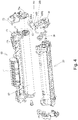
- Figures 4 and 5 are perspective views illustrating the structure of the cartridge B.
- the screws for joining the parts will be omitted for simplicity.
- the cartridge B includes a cleaning unit (photosensitive member holding unit, drum holding unit, image bearing member holding unit, first unit) 60 and a developing unit (developer carrying member holding unit, second unit) 20.
- the process cartridge is a process cartridge in which at least one of the electrophotographic photosensitive member and the process means acting thereon is integrated into a cartridge, and the process cartridge is detachably mountable to the main assembly (apparatus main assembly) of the electrophotographic image forming apparatus.
- process means include charging means, developing means and cleaning means.
- the cleaning unit 60 includes the drum 62, the charging roller 66, the cleaning member 77, and the cleaning frame 71 for supporting them.
- a drive side drum flange 63 provided on the drive side is rotatably supported by a hole 73a of a drum bearing 73.
- the drum bearing 73 and the cleaning frame 71 can be collectively called a cleaning frame.
- a hole portion (not shown) of a non-driving side drum flange is rotatably supported by a drum shaft 78 press-fitted in a hole portion 71c provided in the cleaning frame 71 on the non-driving side.
- Each drum flange is a supported portion rotatably supported by the bearing portion.
- the charging roller 66 and the cleaning member 77 are disposed in contact with the outer peripheral surface of the drum 62.
- the cleaning member 77 includes a rubber blade 77a which is a blade-shaped elastic member formed of rubber material as an elastic material, and a support member 77b which supports the rubber blade.
- the rubber blade 77a is in contact with the drum 62 in the counter direction with respect to the rotational direction of the drum 62. That is, the rubber blade 77a is in contact with the drum 62 so that its free end portion faces the upstream side in the rotational direction of the drum 62.
- the waste toner removed from the surface of the drum 62 by the cleaning member 77 is stored in the waste toner chamber 71b formed by the cleaning frame 71 and the cleaning member 77.
- a scooping sheet 65 for preventing the waste toner from leaking from the cleaning frame 71 is provided at the edge of the cleaning frame 71 so as to be in contact with the drum 62.
- the charging roller 66 is rotatably mounted to the cleaning unit 60 via charging roller bearings (not shown) at opposite end portions with respect to the longitudinal direction of the cleaning frame 71.
- the longitudinal direction of the cleaning frame 71 (the longitudinal direction of the cartridge B) is substantially parallel to the direction (the axial direction) in which the rotation axis of the drum 62 extends. Therefore, the axial direction of the drum 62 is intended in the case of merely longitudinal direction or simply axial direction is referred to without particular notice.
- the charging roller 66 is pressed against the drum 62 as the charging roller bearing 67 is pressed toward the drum 62 by the urging member 68.
- the charging roller 66 is rotationally driven by the rotation of the drum 62.
- the developing unit 20 includes a developing roller 32, a developing container 23 that supports the developing roller 32, a developing blade 42, and the like.
- the developing roller 32 is rotatably mounted to the developing container 23 by bearing members 27 ( Figure 5 ) and 37 ( Figure 4 ) provided at the opposite end portions.
- a magnet roller 34 is provided inside the developing roller 32.
- a developing blade 42 for regulating the toner layer on the developing roller 32 is disposed.
- a gap maintaining member 38 is mounted to the developing roller 32 at opposite end portions of the developing roller 32, and by the contact of the gap maintaining member 38 with the drum 62, the developing roller 32 is held with a small gap from the drum 62.
- a blowing prevention sheet 33 for preventing toner from leaking from the developing unit 20 is provided at the edge of the bottom member 22 so as to abut against the developing roller 32.
- a feeding member 43 is provided in the toner chamber 29 formed by the developing container 23 and the bottom member 22. The feeding member 43 stirs the toner accommodated in the toner chamber 29 and conveys the toner to the toner supply chamber 28.
- the cartridge B is formed by combining the cleaning unit 60 and the developing unit 20 with each other.
- the center of the first developing supporting boss 26a of the bearing member 26 with respect to the first suspending hole 71i on the driving side of the cleaning frame 71, and the center of the developing second supporting boss 27a with respect to the second suspending hole 71j on the non-driving side are first aligned with each other. More specifically, by moving the developing unit 20 in the direction of the arrow G, the first developing supporting boss 26a and the developing second supporting boss 27a are fitted in the first suspending hole 71i and the second suspending hole 71j. By this, the developing unit 20 is movably connected to the cleaning unit 60. More specifically, the developing unit 20 is connected to the cleaning unit 60 so as to be rotatable relative to each other. Thereafter, the cartridge B is constructed by assembling the drum bearing 73 with the cleaning unit 60.
- first end 46Rb of the driving side urging member 46R is fixed to the surface 26b of the bearing member 26, and the second end 46Ra abuts against the surface 71k which is a part of the cleaning unit.
- first end portion 46Ra of the non-driving side urging member 46R is fixed to the surface 23k of the developing container 23, and the second end portion 46Rb abuts against the surface 711 which is a part of the cleaning unit.
- the driving side urging member 46L ( Figure 5 ) and the non-driving side urging member 46R ( Figure 4 ) are in the form of compression springs.
- the driving side urging member 46L and the non-driving side urging member 46R urges the developing unit 20 against the cleaning unit 60, thereby reliably pressing the developing roller 32 toward the drum 62.
- the developing roller 32 is held at a predetermined gap from the drum 62 by the gap maintaining members 38 mounted on the opposite end portions of the developing roller 32.
- Part (a) and part (b) of Figure 1 are perspective views of cartridges for explaining the shape around the drive transmission portion.
- Part (a) of Figure 6 is a perspective view of a cylindrical cam
- part (b) of Figure 6 is a perspective view of the first side plate as viewed from the outside of the apparatus main assembly A
- part (c) of Figure 6 is a sectional view (a direction of an arrow in part (b) of Figure 6 ) in which a cylindrical cam is mounted to the first side plate.
- Part (a) of Figure 7 is a sectional view of an image forming apparatus link portion for explaining a link structure
- part (b) of Figure 7 is a cross sectional view of the image forming apparatus driving for explaining movement of the drive transmission member.
- Part (a) of Figure 8 is a cross-sectional view of the driving side guide portion of the image forming apparatus for explaining the mounting of the cartridge
- part (b) of Figure 8 is a cross-sectional view of the non-driving side guide portion of the image forming apparatus for explaining the mounting of the cartridge
- Figure 9 is an illustration of the image forming apparatus driving train portion for explaining the positional relationship of the drive train before closing the opening/closing door
- Part (a) of Figure 10 is an illustration of the image forming apparatus positioning portion (just before fitting) for explaining the positioning of the process cartridge B in the longitudinal direction.
- Part (b) of Figure 10 is an illustration (after fitting) of the image forming apparatus positioning portion for explaining the positioning of the process cartridge B in the longitudinal direction.
- Part (a) of Figure 11 is a drive-side cross-sectional view of the image forming apparatus for explaining the positioning of the cartridge.
- Part (b) of Figure 11 is a non-driving side sectional view of the image forming apparatus for explaining the positioning of the cartridge.
- Part (a) of Figure 12 is a cross-sectional view of the image forming apparatus link portion for explaining the link structure
- part (b) of Figure 12 is a cross-sectional view of the image forming apparatus drive portion for explaining the movement of the drive transmission member.
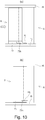
- Part (a) of Figure 13 is a perspective view of the drive transmission member for explaining the shape of the drive transmission member.
- Part (b) of Figure 13 is an illustration of the drive transmission portion of the main assembly A for explaining the drive transmission portion.
- Figure 15 is a perspective view of a drive portion of the image forming apparatus for explaining the engagement space of the drive transmission portion.
- Figure 16 is a cross-sectional view of the drive transmission member for explaining the engagement space of the drive transmission member.
- Figure 17 is a sectional view of the drive transmission member for explaining the engagement of the drive transmission member.
- the apparatus main assembly A is provided with the opening/closing door 13, the cylindrical cam link 85, the cylindrical cam 86, the cartridge pressing members 1, 2, the cartridge pressing springs 19, 21, and a front plate 18.
- the main assembly A is provided with a drive transmission member bearing 83, a drive transmission member 81, and a drive transmission member urging spring 84.
- the apparatus main assembly A is provided with a first side plate 15 provided on the driving side, and a side plate 16 ( Figure 10a ) provided on the non-driving side.
- the opening/closing door 13 is for opening and closing a mounting portion (a space for accommodating the cartridge) for mounting the cartridge B.
- the opening/closing door 13 is rotatably mounted to the first side plate 15 and the side plate 16.
- the cylindrical cam 86 is mounted to the first side plate 15 so as to be rotatable and movable in the longitudinal direction AM. It has two inclined portions 86a, 86b and has one end portion 86c continuous to the inclined portion on the non-driving side in the longitudinal direction.
- the first side plate 15 has two inclined surface portions 15d, 15e opposed to the two inclined surface portions 86a, 86b and an end surface 15f opposed to the one end portion 86c of the cylindrical cam 86.
- the cylindrical cam link 85 has bosses 85a, 85b at the opposite end portions.
- the bosses 85a, 85b are rotatably mounted in the mounting hole 13a provided in the opening/closing door 13 and in the mounting hole 86e provided in the cylindrical cam 86, respectively.
- the rotating cam link 85 moves in interrelation with the opening/closing door 13.
- the cylindrical cam 86 is rotated so that the inclined surface portions 86a and 86b first contact the inclined surface portions 15d and 15e provided on the first side plate 15, respectively.
- one end (fixed end 81c) of the drive side in the axial direction of the drive transmission member 81 is fitted to the drive transmission member bearing 83 and supported so as to be rotatable and movable in the axial direction.
- the center portion 81d in the longitudinal direction of the drive transmission member 81 is provided with a gap M with respect to the first side plate 15.
- the drive transmission member 81 has an abutment surface 81e, and the cylindrical cam 86 has the other end portion 86d opposite to the abutment surface 81e.
- the drive transmission member spring 84 is a compression spring, and one end portion 84a is in contact with a spring seat 83a provided on the drive transmission member bearing 83, and the other end portion 84b is in contact with a spring seat 81f provided on the drive transmission member 81.
- the drive transmission member 81 is urged to the non-drive side in the axial direction (the left side in part (b) of Figure 7 ).
- the abutment surface 81e of the drive transmission member 81 and the other end portion 86d of the cylindrical cam 86 are in contact with each other by this urging.
- the cylindrical cam 86 is a retracting member (retracting mechanism) for moving the drive transmitting member 81 to the retracted position in interrelation with the movement of the opening/closing door 13 to the open position.
- the first side plate 15 has an upper guide rail 15 g and a guide rail 15h
- the side plate 16 is an upper guide rail 16d and a guide rail 16e, as a guide.
- the drum bearing 73 provided on the driving side of the cartridge B has a guided portion (portion to be guided) 73 g and a rotation stopped portion (portion to be stopped) 73c.
- the guided portion 73 g and the rotation stopped portion 73c are disposed on the upstream side (arrow AO side in Figure 16 ) of the axis of the coupling projection 63b (part (a) in Figure 1 , the details will be described hereinafter).
- the mounting direction of the cartridge B is a direction substantially perpendicular to the axis of the drum 62.
- upstream or downstream in the mounting direction they are defined in the moving direction of the cartridge B just before the mounting thereof to the apparatus main assembly A is completed.
- the cleaning frame 71 is provided with a positioned portion (position to be positioned) 71d and a rotation stopping portion 71 g on the non-drive side in the longitudinal direction.
- the guided portion 73 g and the rotation stopping portion 73c of the cartridge B are guided by the upper guide rail 15 g and the guide rail 15h of the apparatus main assembly A, at the driving side of the cartridge B.
- the positioned portion 71d of the cartridge B and the rotation stopping portion 71 g are guided by the guide rail 16d and the guide rail 16e of the apparatus main assembly A.
- a developing roller gear (developing gear) 30 is provided at the end portion of the developing roller 32 ( Figure 9 and part (b) of Figure 13 ). That is, the developing roller gear 30 is mounted to the shaft portion (shaft) of the developing roller 32.
- the developing roller 32 and the developing roller gear 30 are coaxial with each other, and rotate about the axis Ax2 shown in Figure 9 .
- the developing roller 32 is arranged such that the axis Ax2 thereof is substantially parallel to the axis Ax1 of the axis of the drum 62. Therefore, the axial direction of the axial direction (developing roller gear 30) of the developing roller 32 is substantially the same as the axial direction of the drum 62.
- the developing roller gear 30 is a drive input gear (a cartridge side gear, a drive input member) to which a driving force (rotational force) is inputted from the outside of the cartridge B (that is, the apparatus main assembly A).
- the developing roller 32 is rotated by the driving force received by the developing roller gear 30.
- a space 87 opened so as to expose the developing roller gear 30 and the coupling projection 63b is provided on the drum 62 side with respect to the developing roller gear 30.
- the coupling projection 63b is formed on the drive side drum flange 63 mounted to the end of the drum ( Figure 9 ).
- the coupling projection 63b is a coupling portion (a drum side coupling portion, a cartridge side coupling portion, a photosensitive member side coupling portion, an input coupling portion, or a drive input portion) to which a driving force (rotational force) is inputted from the outside of the cartridge B (that is, the apparatus main assembly A) ( Figure 9 ).
- the coupling projection 63b is disposed coaxially with the drum 62. That is, the coupling projection 63b rotates about the axis Ax1.
- the drive side drum flange 63 including the coupling projection 63b is also referred to as a coupling member (a drum side coupling member, a cartridge side coupling member, a photosensitive member side coupling member, a drive input coupling member, an input coupling member).
- the side on which the coupling projection 63b is provided corresponds to the drive side, and the opposite side corresponds to the non-drive side.
- the developing roller gear 30 has a gear portion (input gear portion, cartridge side gear portion, developing side gear portion) 30a and an end surface 30a1 provided on the driving side of the gear portion (parts (a) and part (b) of Figure 1 , and Figure 9 ).
- Teeth (gear teeth) formed on the outer periphery of the gear portion 30a are helical teeth inclined with respect to the axis of the developing roller gear 30. That is, the developing roller gear 30 is a helical tooth gear (part (a) of Figure 1 ).
- the "helical tooth” also includes a shape in which a plurality of projections 232a are arranged along a line inclined with respect to the axis of the gear to substantially form the helical tooth portion 232b ( Figure 14 ).
- the gear 232 has a large number of projections 232b on its circumferential surface.
- the set of five projections 232b can be regarded as forming a row inclined with respect to the axis of the gear. Each of the rows of these five projections 232b corresponds to the teeth of the aforementioned gear portion 30a.
- the drive transmission member (drive output member, main assembly side drive member) 81 has a gear portion (main assembly side gear portion, output gear portion) 81a for driving the developing roller gear 30.
- the gear portion 81a has an end surface 81a1 at the end on the non-driving side (parts (a) and part (b) of Figure 13 ).
- the teeth (gear teeth) formed on the gear portion 81a are also helical teeth inclined with respect to the axis of the drive transmission member 81. That is, the drive transmission member 81 is also provided with a portion of the helical tooth gear.
- the drive transmission member 81 is provided with a coupling recess 81b.
- the coupling recess 81b is a coupling portion (main assembly side coupling portion, output coupling portion) provided in the device main assembly side.
- the coupling recess 81b is a recess which can be coupled with a coupling projection 63b provided on the drum side and which is formed in the projection (cylindrical portion) provided at the free end of the drive transmission member 81.
- the space (space) 87 ( Figure 1 ) constituted so that the gear portion 30a and the coupling projection 63b are exposed is for placing the gear portion 81a of the drive transmission member 81 when the cartridge B is mounted in the apparatus main assembly A. Therefore, the space 87 is larger than the gear portion 81a of the drive transmission member 81 ( Figure 15 ).
- the drive transmission member 81 does not interfere with the cartridge B when the cartridge B is mounted to the apparatus main assembly A. As shown in Figure 15 , the space 87 allows the cartridge B to be mounted on the apparatus main assembly A by disposing the drive transmission member 81 therein.
- the gear teeth formed in the gear portion 30a are arranged in a position close to the peripheral surface of the drum 62.
- the gear portion 30a of the developing roller gear 30 is exposed from the driving side developing side member 26, the gear portion 81a meshes with the gear portion 30a without interfering with the driving side developing side member 26, and therefore, the driving transmission is enabled.
- the exposed portion of the gear portion 30a is disposed more outside (drive side) of the cartridge B than the leading end 63b1 of the coupling projection 63b and faces the axis of the drum ( Figure 1 , Figure 9 ).
- the gear teeth disposed on the exposed portion 30a3 of the gear portion 30a faces the rotational axis Ax1 of the drum 62 (rotational axis of the coupling portion 63b) Ax1.
- the axis Ax1 of the drum 62 is above the exposed portion 30a3 of the gear portion 30a.
- the gear portion 30a of the developing roller gear 30 and the gear portion 81a of the drive transmission member 81 can mesh with each other in the process of mounting the above-described cartridge B to the apparatus main assembly A.
- the center (axis) of the gear portion 30a is disposed on the upstream side (the side of the arrow AO in Figure 16 ) of the center (axis) of the drum 62.
- the drum bearing 73 has a fitted portion 73h as a portion to be positioned (position portion, axial aligned part) in the longitudinal direction (axial direction).
- the first side plate 15 of the apparatus main assembly A has a fitting portion 15j that can be fitted with the fitted portion 73h.
- the fitted portion 73h of the cartridge B is fitted to the fitting portion 15j of the apparatus main assembly A in the above-described mounting process, by which the position in the longitudinal direction (axial direction) of the cartridge B is determined (b)).
- the fitted portion 73h is in the form of a slit (groove) (part (b) of Figure 1 ).
- the first side plate 15 has an upper positioning portion 15a, a lower positioning portion 15b and a rotation stopping portion 15c
- the side plate 16 has a positioning portion 16a and a rotation stopping portion 16c.
- the drum bearings 73 is provided with an upper positioned portion (first positioned portion, first projection, first projecting portion) 73d and the lower positioned portion (second positioned portion, second projection, second overhang portion) 73f.
- the cartridge pressing members 1, 2 are rotatably mounted on the opposite both end portions, in the axial direction, of the opening/closing door 13, respectively.
- the cartridge pressing springs 19, 21 are mounted on the opposite end portions, in the longitudinal direction, of the front plate provided in the image forming apparatus A, respectively.
- the drum bearing 73 has the pressed portion 73e as an urging force receiving portion, and the cleaning frame 71 has a pressed portion 71o on the non-driving side ( Figure 3 ).
- the cartridge B and the drum 62 are positioned on the drive side.
- the positioned portion 71d of the cartridge B and the rotation-stopped portion 71 g come into contact with the positioning portion 16a and the rotation stopping portion 16c of the apparatus main assembly A, respectively.
- the cartridge B and the drum 62 are positioned on the non-driving side.
- the upper positioned portion 73d and the lower positioned member 73f are disposed in the neighborhood of the drum 62.
- the upper positioned portion 73d and the lower positioned member 73f are arranged along the rotational direction of the drum 62.
- the drum bearing 73 it is necessary to assure a space (circular-arc shaped recess) 731 for disposing the transfer roller 7 ( Figure 11 ) between the upper positioned portion 73d and the lower positioned member 73f. Therefore, the upper positioned portion 73d and the lower positioned member 73f are arranged apart from each other.
- the upper positioned portion 73d and the lower positioned member 73f are in the form of projections projecting inward in the axial direction from the drum bearing 73. As described above, it is necessary to assure the space 87 around the coupling projection 63b. Therefore, the upper positioned portion 73d and the lower positioned member 73f do not project outward in the axial direction, but instead project inward to assure the space 87.
- the upper positioned portion 73d and the lower positioned member 73f are disposed so as to partially cover the driving side drum flange 63 provided at the end of the photosensitive drum 62.
- the upper positioned portion 73d and the driving side drum flange 63 are projected on the axis of the drum 62, at least a part of the projected areas of the upper positioned portion 73d and the driving side drum flange 63 overlap each other.
- the lower positioned portion 73f is also the same as the upper positioned portion 73d ( Figure 11 ).
- the pressed portions 73e and 71o are projecting portions of the frame of the cleaning unit provided on one end side (drive side) and the other end side (non-drive side) of the cartridge B in the longitudinal direction, respectively.
- the pressed portion 73e is provided on the drum bearing 73.
- the pressed portions 73e and 71o are projected in a direction crossing with the axial direction of the drum 62 away from the drum 62.
- the drive side drum flange 63 has a coupling projection 63b on the drive side, a free end portion 63b1 at the free end of the coupling projection 63b.
- the drive transmission member 81 has a coupling recess 81b and a free end portion 81b1 of the coupling recess 81b on the non-driving side.
- the drive transmission member 81 present at the retracted position moves to the non-drive side (the side approaching the cartridge B) in the longitudinal direction by the drive transmission member spring 84. Since the gear teeth of the gear portion 81a and the gear portion 30a are inclined with respect to the moving direction of the drive transmission member 81, the gear teeth of the gear portion 81a abuts to the gear teeth of the gear portion 30a by the movement of the drive transmission member 81. At this point of time, the movement of the drive transmission member 81 to the non-drive side is stopped.
- the drum bearing 73 has a recess bottom surface 73i.
- the drive transmitting member 81 has a bottom portion 81b2 as a positioning portion on the bottom of the coupling recess 81b.
- the coupling recess 81b of the drive transmission member 81 is a hole having a substantially triangular cross section.
- the gear portion 81a of the drive transmission member 81 is a helical gear having gear teeth twisted in the counterclockwise direction N as going to the drive side as viewed from the non-drive side (cartridge side).
- the gear portion 81a and the coupling recess portion 81b are arranged so that the axis of the gear portion 81a and the axis of the coupling recess portion 81b overlap the axis of the drive transmission member 81. That is, the gear portion 81a and the coupling recess portion 81b are disposed coaxially (concentrically).
- the coupling projection 63b of the drive side drum flange 63 has a substantially triangular cross section and is a projection shape (projection, projection).
- the coupling projection 63b is twisted in the counterclockwise direction O in the direction from the drive side (the free end side of the coupling projection 63b) toward the non-drive side (the bottom side of the coupling projection 63b) ( Figure 1 ). That is, the coupling projection 63b is inclined (twisted) in the counterclockwise direction (the direction of rotation of the drum) as going from the outside toward the inside of the cartridge in the axial direction.
- a portion (ridge line) forming a corner of the triangular prism (a apex of the triangle) is a driving force receiving portion that actually receives the driving force (rotational force) from the coupling recess portion 81b.
- the driving force receiving portion is inclined toward the rotational direction of the drum as going inward from the outside of the cartridge in the axial direction.
- the inner surface (inner peripheral surface) of the coupling recessed portion 81b serves as a driving force applying portion for applying a driving force to the coupling projection 63b.
- the shape of the cross sections of the coupling projection 63b and the coupling recess portion 81b is not the exact triangles (polygons) in that corners being collapsed or rounded, but they are called substantial triangles (polygons). That is, the coupling projection 63b has a shape of a projection which is substantially a twisted triangular prism (square prism). However, the shape of the coupling projection 63b is not limited to such a shape.
- the shape of the coupling projection 63b may be changed as long as it can be coupled with the coupling recess 81b, that is, if the engaging and driving can be performed.
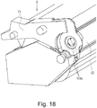
- three bosses 163a may be arranged at the apexes of a triangle, and each boss 163a may be twisted around the axis of the drum 62 ( Figure 18 ).
- the gear portion 30a of the developing roller gear 30 is a helical gear and has a shape twisted (inclined) in the clockwise direction P from the drive side to the non-drive side ( Figure 1 ). That is, the gear teeth (helical teeth) of the gear portion 30a are inclined (twisted) in the clockwise direction P (rotational direction of the developing roller and developing roller gear) in the axial direction of the gear portion 30a from the outside toward the inside of the cartridge. That is, the gear 30a is inclined (twisted) in the direction opposite to the rotational direction of the drum 62 as going from the outside toward the inside in the axial direction.
- the drive transmission member 81 rotates clockwise CW (reverse direction of arrow N in Figure 13 ) as viewed from the non-drive side (cartridge side) by a motor (not shown). Then, a thrust force (a force generated in the axial direction) is produced by the engagement of the helical teeth of the gear portion 81a of the drive transmission member 81 with the gear portion 30a of the developing roller gear 30.
- the force FA in the axial direction (longitudinal direction) is applied to the drive transmission member 81, and the drive transmission member 81 tends to move to the non-drive side (the side closer to the cartridge) in the longitudinal direction. That is, the drive transmission member 81 approaches and contacts to the coupling projection 63b.
- the force FC directed toward the non-driving side in the longitudinal direction acts on the drive transmission member 81.
- This force FC and the above-described force FA together make the drive transmission member 81 move further toward the non-drive side (the side approaching the cartridge) in the longitudinal direction. That is, the coupling projection 63 makes the drive transmission member 81 close to the coupling projection 63b of the cartridge B.
- the drive transmission member 81 drawn by the coupling projection 63b is positioned in the longitudinal direction (axial direction) by the free end portion 81b1 of the drive transmission member 81 contacting the recess bottom surface 73i of the drum bearing 73.
- reaction force FB of the force FC acts on the drum 62, and by this reaction force (drag) FB, the drum 62 moves in the longitudinal direction toward the drive side (the side approaching the drive transmission member 81, the outside of the cartridge B). That is, the drum 62 and the coupling projection 63b are drawn to the side of the drive transmission member 81. By this, the front end portion 63b1 of the coupling projection 63b of the drum 62 abuts against the bottom portion 81b2 of the coupling recess portion 81b. By this, the drum 62 is also positioned in the axial direction (longitudinal direction).
- the coupling projection 63b and the coupling recess portion 81b are attracted to each other, so that the positions in the axial direction of the drum 62 and the drive transmission member 81 are determined.
- the drive transmitting member 81 is in the driving position (advanced position). In other words, the drive transmitting member 81 is in the position for transmitting the driving forces to the coupling projection 63b and the gear portion 30b, respectively, and is in the position advanced to the cartridge.
- the center of the free end of the drive transmission member 81 is determined with respect to the drive side drum flange 63 by the alignment action of triangular shape of the coupling recess 81b. That is, the drive transmission member 81 is centered or aligned with respect to the drum flange 63, and the drive transmission member 81 and the photosensitive member become coaxial. By this, the drive can be transmitted from the drive transmission member 81 to the developing roller gear 30 and the driving side drum flange 63 with high accuracy.
- the coupling recess 81b and the coupling projection 63b engaging with the coupling recess 81b can also be deemed as an alignment portion. That is, by engaging the coupling recess portion 81b and the coupling projection 63b with each other, the drive transmission member 81 and the drum become coaxial with each other.
- the coupling recessed portion 81b is referred to as a main assembly side alignment portion (image forming device side alignment portion), and the coupling projection 63b is referred to as a cartridge side alignment portion.
- the engagement of the couplings is assisted by the force FA and the force FC toward the non-driving side acting on the drive transmission member 81.
- the positional accuracy of the drive transmission member 81 with respect to the cartridge B can be enhanced.
- the positional accuracy in the longitudinal direction between the gear portion 30a of the developing roller gear 30 and the gear portion 81a of the drive transmission member 81 is improved, and therefore, the width of the gear portion 30a of the developing roller gear 30 can be made small. It is possible to downsize the cartridge B and the apparatus main assembly A to which the cartridge B is mounted can be downsized.
- the gear portion 81a of the drive transmission member 81 and the gear portion 30a of the developing roller gear 30 have helical teeth.
- the helix teeth have higher contact ratios of the gears than a spur gear.
- the direction in which the helical teeth of the gear portion 30a and the gear portion 81a are twisted is determined so that the force (force FA and force FB) that the gear portion 30a and the gear portion 81a are attracted to each other is produced. That is, when the gear portion 30a and the gear portion 81a rotate in a state of meshing engagement, the force of attracting the coupling recess 81b provided on the drive transmission member 81 and the coupling projection 63b provided on the end portion of the photosensitive drum 62 to each other is produced. By this, the drive transmission member 81 moves toward the cartridge B side, and the coupling recess portion 81b approaches the coupling projection 63b. By this, the coupling (coupling) between the coupling recess 81b and the coupling projection 63b is assisted.
- the drive transmission member 81 is urged toward the coupling projection 63b by the elastic member (drive transmission member spring 84) (part (a) of Figure 7 ).
- the force of the drive transmission member spring 84 can be weakened correspondingly to the force FA and the force FC produced (part (b) of Figure 13 ). Then, the frictional force between the drive transmission member spring 84 and the drive transmission member 81, which occurs when the drive transmission member 81 rotates, is also reduced, and therefore, the torque required to rotate the drive transmission member 81 decreases.
- the load applied to the motor for rotating the drive transmission member 81 can also be reduced.
- the sliding noise between the drive transmission member 81 and the drive transmission member spring 84 can also be reduced.
- the drive transmission member 81 is urged by the elastic member (spring 84), but the elastic member is not necessarily required. If the gear portion 81a and the gear portion 30a at least partly overlap each other in the axial direction, and the gear portion 81a and the gear portion 30a mesh with each other when the cartridge B is mounted to the apparatus main assembly A, the elastic member can be eliminated. That is, in such a case, when the gear portion 81a rotates, a force for attracting the coupling projection 63b and the coupling recess portion 81b to each other is produced due to the engagement between the gear portion 81a and the gear portion 30a.
- the drive transmission member 81 approaches to the cartridge B due to the force generated by the meshing of the gears.
- the coupling recess portion 81b can be engaged with the coupling projection 63b.
- the helical gear is used for the developing roller gear 30 engaged with the drive transmission member 81, but another gear may be used as long as drive transmission is possible.
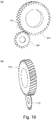
- a spur gear 230 which can enter a gap 81e between the teeth of the drive transmission member 81 is usable.
- the thickness of the spur tooth is 1 mm or less.
- the gear portion 81a of the drive transmission member 81 has helical teeth, and therefore, a force for directing the drive transmitting member 81 toward the non-driving side is produced by engagement between the gear portion 81a and the spur gear 230 ( Figure 19 ).
- the member which applies the load of the developing roller to the gear portion 81a of the drive transmission member 81 may not be the developing roller gear.
- Figure 20 discloses a drive input gear 88 that meshes with the drive transmission member 81, a developing roller gear 80 provided on the developing roller, idler gears 101 and 102, and a feeding gear (stirring gear, developer feeding gear) 103.
- the driving force is transmitted from the drive input gear 88 to the developing roller gear 80 by way of one idler gear 101.
- the idler gear 101 and the developing roller gear 80 constitutes a drive transmission mechanism (a cartridge side drive transmission mechanism, a development side drive transmission mechanism) for transmitting a driving force from the drive input gear 88 to the developing roller 32.
- the idler gear 102 is a gear which transmits the driving force from the drive input gear 88 to the stirring gear 103.
- the feeding gear 103 is mounted on the feeding member 43 ( Figure 3 ), and the feeding member 43 is rotated by the driving force received by the feeding gear 103.
- the load applied to the gear portion 81a of the drive transmission member 81 may not be the load of the developing roller.
- the driving force received by the drive input gear 88 is transmitted to only the feeding member 43 ( Figure 3 ) by way of the idler gear 102 without being transmitted to the developing roller 32.
- the cartridge B needs a gear 162a and the like for transmitting the driving force from the drum 62 to the developing roller gear 30.
- a cylindrical boss (projection) 363b may be provided on one of the drive transmission member 381 and the drive-side drum flange 363 and a hole 381b to be fitted with the boss may be provided on the other of them. Even with such a structure, the axis of the drive transmission member 381 and the axis of the drum 62 can be aligned.
- the alignment of the drive transmission member 81 is effected in a triangular shape of the coupling projection and recess portions 81b, 63b, but may be effected by other shapes.
- the drive transmission member 181 shown in Figure 23 has a projection (boss) 181c at the center of the coupling recess 181b.
- the projection 181c is arranged so as to overlap with the axis of the drive transmission member 181 and is a projection projecting along its axis.
- the coupling projection shown in Figure 23 has a recess (recess) for engaging with the projection 181c at the center thereof.
- the recess is arranged so as to overlap with the rotation axis of the drum 62 and is a hollow recessed along this axis.
- the drum 62 is driven by the engagement of the drive transmission member 81 and the coupling projection 63b.
- the driving of the drum 62 can be accomplished through the gears 330b, 95b provided inside the cartridge.
- the developing roller gear 330 is provided with not only the gear portion (input gear portion) 330a for receiving drive from the gear portion 81a of the drive transmission member 81 but also a gear portion 330b (output gear portion) for outputting driving force toward the drum 62.
- the drum flange 95 fixed to the end of the drum 62 does not have a coupling projection.
- the drum flange 95 has a cylindrical portion 95a.
- the cylindrical portion 95a provided at the end portion of the drum 62 is engaged with the coupling recess portion 81b provided at the free end of the drive transmission member 81, thereby functioning as the positioning of the drive transmission member 81.
- the recessed portion 81b and the cylindrical portion 95a function as an alignment portion for aligning the axis of the drive transmission member 81 and the axis of the drum 62.
- Figure 25 shows a modified example of such a shape of the alignment portion.
- Figure 25 shows a state in which a cylindrical portion 95a is provided on the drum flange 63.
- the shape of the alignment portion 195b constitutes only a part of a circle. If the arc portion 195c of the alignment portion 195b is sufficiently larger than the arc shape of the lightening portion 81b3 ( Figure 13 ), the alignment portion 195b has a centering action.
- Both structures can be regarded as aligning portions that are substantially coaxial with the drum. That is, each of the alignment portions 95a, 195b, 295c is disposed so as to be centered on the axis of the drum.
- the coupling projection 63b is fixed to the drum 62, but it is also possible to provide a movable coupling projection.
- the coupling 263b shown in Figure 26 is movable in the axial direction with respect to the drum 62, and is biased by a spring 94 toward the driving side in a state in which no external force is applied.
- the coupling projection 263b can retract toward the non-drive side (away from the drive transmission member 81) while contracting the spring 94, by the force received from the drive transmission member 81.
- the end portion 263a of the coupling projection 263b is an inclined portion (inclined surface, chamfered surface).
- the present invention is not limited to such a structure.
- the contact portion on the drive transmission member 81 side contacting the coupling projection 263b may be inclined.
- the cylindrical portion 95a is provided on the drum 62.
- the alignment portion such as the cylindrical portion 95a may be provided on the frame (more particularly, the drum bearing 73) of the cleaning unit 60.
- an arcuate projection 173a for contacting with the periphery of the cylindrical portion 81i is provided on the drum bearing 173.
- the projection 173a is engaged with the cylindrical portion 81i so as to correspond to the alignment portion for aligning the drive transmission member 81.
- the inner circumferential surface of the projection 173a facing the axis side of the drum is the alignment portion.
- the center of the aligning portion is arranged so as to overlap the axis of the drum. That is, the projection 173a is disposed so as to be substantially coaxial with the drum. In addition, a taper (inclined portion) is provided at the edge of the free end of the projection 173a so that when the free end of the projection 173a abuts to the cylindrical portion 81i, the cylindrical portion 81i can be easily guided into an internal space of the projection 173a.
- Part (a) of Figure 28 is a cross-sectional view of the image forming apparatus drive portion as viewed from the driving side for explaining the gap of the coupling section.
- Part (b) of Figure 28 is a cross-sectional view of the image forming apparatus driving portion as viewed from the drive side for explaining the gap of the coupling portion.
- Part (c) of Figure 28 is a sectional view illustrating the meshing force.
- the drum bearing 73 has a restricting portion 73j, as an inclination restricting regulating portion (movement regulating portion, position regulating portion, stopper) for regulating (suppressing) the inclination of the drive transmission member 81 by regulating the movement of the drive transmission member 81.
- the drive transmitting member 81 has a cylindrical portion 81i (part (b) of Figure 28 ) on the non-driving side (the side closer to the cartridge B).
- the cylindrical portion 81i is a cylindrical portion (projection) in which the coupling recess 81b is formed (part (a) of Figure 13 ).
- the gear portion 81a of the drive transmission member 81 and the gear portion 30a of the developing roller gear 30 mesh with each other as shown in Figure 9 when the drive transmission member 81 starts to rotate.
- the coupling recess 81b and the coupling projection 63b are not coupled, or the coupling therebetween is insufficient. Therefore, when the gear portion 81a transmits the driving force to the gear portion 30a, the meshing force FD (part (a) of Figure 28 ) is generated in the gear portion 81a due to the engagement between the gears.
- the drive transmission member 81 is inclined (part (c) of Figure 28 ). That is, the drive transmission member 81 is supported only by the fixed end 81c (end portion on the side remote from the cartridge B in part (b) of Figure 7 ) which is the end portion on the drive side as described above, and therefore, the drive transmission member 81 is inclined with the drive side end portion 81c (fixed end) as a fulcrum. Then, the end (free end, free end) of the drive transmission member 81 on the side where the coupling recess 81b is provided moves.
- the restricting portion 73j is provided in the cartridge B, so that the inclination of the drive transmitting member 81 is restricted (regulated) within a certain range. That is, when the drive transmission member 81 is inclined, the restriction portion 73j supports the drive transmission member 81, thereby suppressing increase of the inclination.
- the regulating portion 73j of the drum bearing 73 is an arcuate curved surface portion arranged so as to face the axis of the drum 62 (the axis of the coupling projection 63b).
- the restricting portion 73j can be regarded as a projecting portion projecting so as to cover the drum axis.
- the structure is such that between the regulating portion 73j and the drum axis is a space in which no constituent element of the process cartridge B is provided, and the drive transmission member 81 is disposed in this space.
- the regulating portion 73j faces the space 87 shown in Figure 1 , and the regulating portion 73j forms the edge (outer edge) of the space 87.
- the restricting portion 73j is disposed at a position where it is possible to suppress the movement (inclination) of the drive transmission member 81 by the meshing force FD.
- the direction in which the meshing force FD is generated is determined by the transverse pressure angle ⁇ of the gear portion 81a (that is, the transverse pressure angle ⁇ of the developing roller gear 30).
- the direction in which the meshing force FD is generated is inclined by (90 + ⁇ ) degrees toward the upstream AK in the rotating direction of the photosensitive drum 62, with respect to an arrow (half line) LN extending from the center 62a of the photosensitive drum (that is, the center of the drive transmission member 81) toward the center 30b of the developing roller gear 30.
- the restricting portion 73j is disposed on this line FDa, and it will suffice if the restricting portion 73j is disposed close to the half line FDa. More specifically, it is desirable that at least a portion of the regulating portion 73j is disposed somewhere in the range of plus or minus 15 ° with respect to the half line FDa.
- the half line FDa is a line obtained by rotating the half straight line LN to the upstream side in the rotational direction of the (90 + ⁇ ) degree drum 62. Therefore, the regulating portion 73j is preferably in the range of (75 + ⁇ ) degrees to (105 + ⁇ ) degrees on the upstream side in the drum rotational direction relative to the half straight line LN with the center of the drum 62 as the origin.
- a plurality of restricting portions 73j may be disposed separately on both sides of the half line FDa so as to sandwich the half straight line FDa therebetween ( Figure 29 ).
- the restricting portion 73j can be regarded as being arranged across the line FDa.
- / /the regulating portion 73j is disposed on the upstream side AO ( Figure 16 ) in the cartridge mounting direction C (part (a) of Figure 11 ) with respect to the center (axis) of the coupling projection 63b. This is to prevent the restriction portion 73j from hindering the mounting of the cartridge B.
- the shortest gap V between the couplings satisfies the following.
- the shortest gap V between the coupling portions also changes. That is, if the phases of the coupling portions are not matched, the shortest gap V between the coupling projection 63b and the coupling recess 81b is smaller than the misalignment amount AB.
- the coupling projection 63b and the coupling recess portion 81b are engaged. This is because the coupling recess 81b contacts the coupling projection 63b while rotating. It can be engaged (coupled) with the coupling projection 63b at the timing when the coupling recess 81b has rotated to such an angle as to satisfy "V > AB".
- the regulating portion 73j and the tooth tips of the drive transmission member 81a do not come into contact with each other during image formation. That is, the distance BB from the center of the drum 62 to the restricting portion 73j (the distance spaced in the direction perpendicular to the axis of the drum) needs to be longer than the radius BF to the tooth free end of the gear portion 81a of the drive transmission member 81. From the above analysis, BB > BF is to be satisfied.
- the restricting portion 73j is formed as a continuous surface. More specifically, the regulating portion 73j is a continuous curved surface (arcuate surface) which is opened toward the axis of the drum 62 and is curved in a bow shape. In other words, it has a bay shape (bay portion) opened to the axis side of the drum 62.
- the restricting portion 89j may be formed by a plurality of portions (plural surfaces 89j) intermittent in the rotational direction of the drum 62.
- the regulating portion can be regarded as forming a bay shape (bay portion) which opens to the axis side of the drum 62.
- the regulating portion shown in Figure 1 and the regulating portion shown in Figure 29 both have a bow shape (a bay shape, a curved surface portion, a curved portion) which opens to the axis side of the drum 62.
- the drive transmission member 81 has the gear portion 81a and the coupling recess 81b on the free end side thereof. And, the drive transmission member 81 is movable forward and backward and can be inclined (inclinable). It is preferable that when the drive transmitting member 81 rotates and advances toward the cartridge side to engage the coupling recess 81b with the coupling projection 63b, the inclination angle of the drive transmission member 81 with respect to the drum 62 is made small. Therefore, as described above, the regulating portion 73j is provided in the cartridge to suppress the inclination angle of the drive transmission member 81 when the drive transmission member 81 is driven.
- the drive transmission member 81 In order to incline the drive transmission member 81 to separate the gear portion 81a from the gear portion 30a, it is preferable that the drive transmission member 81 is inclined so as not to contact with the restriction portion 73j at the time of dismounting the cartridge.
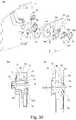
- Part (a) of Figure 30 is a perspective view illustrating the supporting structure of the drive transmission member.
- Part (b) of Figure 30 is a sectional view in the axial direction around the drive transmission member for illustrating the support structure of the drive transmission member when the driving force is applied.
- Part (c) of Figure 30 is a sectional view in the axial direction for illustrating the support structure around the drive transmission member when no driving force is applied.
- Figure 31 is a perspective view illustrating the shape of the first bearing.
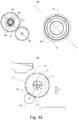
- Part (a) of Figure 32 is a perspective view as viewed from the drive side for illustrating the support structure of the drive side around the drive transmission member.
- Part (b) of Figure 32 is a sectional view taken along a direction perpendicular to the axis for illustrating the supporting structure of the drive side around the drive transmission member.
- Part (c) of Figure 32 is a sectional view taken along the direction perpendicular to the axis for illustrating the supporting structure on the non-drive side around the drive transmission member.
- a second side plate 93 supports a first bearing 94.
- the first bearing 94 supports the outer diameter portion of a second bearing 95 at its inner diameter portion.
- a gap is provided between the first bearing 94 and the second bearing 95, and the first bearing 94 supports the second bearing 95 so that the second bearing 95 can incline. Therefore, the second bearing 95 is supported by the second side plate 93 so as to be inclinable.
- a second side plate (second driving side plate) 93 is provided on the driving side of the apparatus main assembly A.
- the second side plate 93 is a sheet metal (plate-like metal), and a hole portion 93a is provided by drawing this sheet metal.
- the second bearing 95 and the first bearing 94 for supporting the second bearing 95 are fitted in the hole portion 93a of the second side plate 93.
- the drive transmission member 81 is rotatably supported by the second bearing 95. That is, the rear end side of the drive transmission member 81 is supported by the first bearing 94 by way of the second bearing 95.
- the first bearing 94 is a bearing support portion (support portion) for supporting the second bearing 95.
- two first bearings 94 and two second bearings 95 are provided in the hole portion 93a to support the drive transmission member 81.
- the two bearings 94, 95 fitted with a gap provided between them one of them can incline largely (inclinable) with respect to the other, so that the drive transmission member 81 can be more smoothly inclined.
- a V-shaped portion 94a is provided on the inner periphery of the first bearing 94.
- the V-shaped portion 94a is constituted by two projecting portions (projecting portions) projecting from the inner peripheral portion of the first bearing 94.
- the two projecting portions form a V shape, and therefore, these are collectively referred to as V-shaped portion 94a.
- the second bearing 95 When the drive transmission member 81 is driven, the second bearing 95 is held in a substantially horizontal state by bring the second bearing 95 into contact with a V-shaped portion 94a provided by two projecting portions (projecting portions), and by this second bearing 95, the drive transmission member 81 is accurately supported in a substantially horizontal state.
- the V-shaped portion 94a is an attitude determining portion (attitude holding portion) for keeping the attitude of the drive transmission member 81.
- the first bearing 94 is provided with a hole 94b as a rotation stopper.
- the second side plate 93 is provided with a projection 93b.
- the second side plate 93 is provided with three holes 93e around the hole 93g.
- the downstream side of each hole 93e in the rotational direction of the drive transmission member 81 has a width in the radial direction smaller than the width on the upstream side.
- a leg portion 95a is provided on the outer peripheral surface of the second bearing 95.
- the leg portion 95a extends outward in the radial direction from the bearing 95, the free end side thereof is bent and extends along the axial direction toward the non-driving side, and the extreme free end portion further bends and extends radially outward. That is, the leg portion 95a is bent into a crank shape.
- Three such legs 95a are provided at positions corresponding to the three holes 93e, respectively.
- the three leg portions 95a of the second bearing 95 are inserted into the wide area the three hole portions 93e of the second side plate 93. Thereafter, when the second bearing 95 is rotated with respect to the second side plate 93 in the rotational direction of the drive transmission member 81, the three leg portions 95a enter the area where the width of the hole portion 93e is narrowed, the free end portions 95a of the leg portion 95a is locked to the second side plate 93.
- the free end of the foot portion 95a is bent in a crank shape and extends toward the outside in the radial direction. Therefore, the free end of the leg portion 95a contacts the second side plate 93, whereby the movement of the second bearing 95 in the axial direction is restricted.
- the second bearing 95 is fixed in the axial direction. Meanwhile, the play is provided between the leg portion 95a of the second bearing 95 and the hole portion 93e of the second side plate 93, and therefore, the second bearing 95 can be inclined with respect to the second side plate 93 within the range of this gap.
- the second bearing 95 has a boss portion 95b, and a fixed end side thereof extends in the radial direction from the outer peripheral surface, and a free end side thereof bends with respect to the fixed end side and extends toward the non-driving side along the axial direction. This is the rotation stopper of the second bearing 95.
- the second side plate 93 is provided with a hole portion 93f as a rotation stopper at a position corresponding to the boss portion 95b. When the boss portion 95b enters the hole portion 93f, the rotation of the second bearing 95 relative to the second side plate 93 is restricted. That is, the second bearing 95 is fixed in the rotational direction.
- the second side plate 93 is provided with the drive idler gear (gear member) 96 for transmitting drive from a motor (not shown) to the drive transmission member 81.
- the V-shaped portion 94a is provided near the center in the axial direction of the first bearing 94 and is provided in the neighborhood of the second gear portion 81j of the drive transmission member 81 in the axial direction.
- the second bearing 95 (the drive transmission member 91) is inclined with the V-shaped portion 94a as a fulcrum. Therefore, the inclination fulcrum of the drive transmission member 81 and the second gear portion 81j of the drive transmission member 81 are positioned close to each other in the axial direction.
- the V-shaped portion 94a has a small length HB in the axial direction, and in this embodiment, it is about 0.5 mm in this embodiment.
- the phase of the V-shaped portion 94a is located at a position where the drive transmission member 81 can be stably held, when the meshing force CG (part (a) in Figure 32 ) is produced by the meshing engaging between the idler gear 96 and the second gear portion 81j of the drive transmission member 81. That is, when the drive transmission member 81 receives the meshing force CG, the second bearing 95 supporting the drive transmission member 81 tends to move in the direction of the meshing force CG. By disposing the V-shaped portion 94a on the downstream side in the CG direction, the second bearing 95 is abutted against the V-shaped portion 94a of the first bearing 94.
- the second bearing 95 is stably held by the first bearing 94, and the drive transmission member 81 is also stably held via the second bearing 95.
- the position in the radial direction of the V-shaped portion 94a is such that when the second bearing 95 abuts against the V-shaped portion 94a, the inter-axis distance between the drive idler gear 96 and the second gear portion 81j of the drive transmission member 81 is proper. That is, the drive transmission member 81 is held at a position where the idler gear 96 and the drive transmission member 81 can mesh with each other.
- the drive transmission member 81 can incline within the play by gravity with the V-shaped portion 94a as a fulcrum.
- the second bearing 95 is urged to the V-shaped portion 94a by the meshing force of the drive transmission member 81, so that the drive transmission member 81 takes the first attitude in which the distance between the second gear portion 81j and the drive idler gear 96 is accurately determined. By this, it is possible to transmit rotational force with high accuracy.
- the drive transmission member 81 is supported together with a play between the drive transmission member 81 and the hole portion 15k by a hole portion 15k provided in the first side plate (first drive side plate) 15.
- the drive transmission member 81 can take the second attitude in which the axis thereof is inclined.
- the hole portion 15k of the first side plate 15 is provided with a V-shaped portion 15m as a bearing (holding portion) of the drive transmission member 81 when the cartridge B is not mounted.
- the V-shaped portion 15m is disposed below the hole portion 15k of the first side plate 15. It is to support the drive transmission member 81 which is inclined by the gravity.
- the V-shaped portion 15m is not disposed at the lowermost portion of the hole portion 15k in the gravitational direction (vertical direction) CN, and the drive transmission member 81 is inclined in a direction different from the direction of gravity, by being held in the V-shaped portion 15m.
- the drive transmission member 81 is held by the V-shaped portion 15m so that the free end side thereof is inclined in the direction toward the lower right part.
- the phase of the V-shaped portion 15m is determined so as to place the center of the first gear portion 81a of the drive transmission member 81 in a predetermined range when the drive transmission member 81 abuts against the V-shaped portion 15m. That is, the V-shaped portion 15m is provided such that the center of the first gear portion 81a is placed on an arc CI having a radius CH equal to the distance between the center of the developing roller 32 and the center of the drum 62 around the developing roller 32.
- the play of the drive transmitting member 81 and the hole portion 15k of the side plate 15 other than the V-shaped receiving portion 15m is about 1 mm at the time of image formation.
- the drive transmission member 81 abuts against the V-shaped portion 15m by its own weight in a state where no driving is applied, and the distance between the developing roller gear 30 and the gear portion 81a of the drive transmission member 81 is appropriately set.
- the drive transmission member 81 can stably make the meshing engagement with the developing roller gear 30.
- the drive transmission member 81 is inclined by using the own weight of the drive transmission member 81 and placed at a predetermined position.
- the drive transmission member 81 may be urged toward the V-shaped portion 15m side by a spring 97.
- the spring 97 is an inclination imparting portion (urging member, elastic member) that inclines the drive transmission member 81 by applying a force to the drive transmission member 81 to urge it.
- the drive transmission member 81 urged by the spring 97 is supported by the V-shaped portion 15m, whereby the drive transmission member 81 is held at the predetermined inclination angle.
- the spring 97 can be regarded as a holding portion for holding the drive transmission member 81 in an inclined state in a predetermined direction.
- one of the V-shaped portion 15m and the spring 97 may be referred to as first holding portion and second holding portion, respectively.
- the V-shaped portion 15m and the spring 97 may be collectively referred to as a holding portion in some cases.
- Part (a) of Figure 34 is a sectional view perpendicular to the axis concerning the structure of the periphery of the drive transmission member, and shows a cross-section as viewed from the drive side in a state where the drive transmission member is in the retracted position.
- Part (b) of Figure 34 is a sectional view illustrating a state in which the driving member is in the driving position (advanced position).
- Part (c) of Figure 34 is a sectional view as viewed from the drive side for explaining the movement of the drive transmission member when removing the cartridge out.
- the second side plate 93 is provided with a projection 93c extending toward the non-driving side at a position opposed to a portion having a smaller diameter than the tooth bottom portion of the second gear portion 81j of the drive transmission member 81.
- This projection 93c has a height HH enough to contact with the drive transmission member 81 when the opening/closing door 13 is opened and the drive transmission member 81 retracts to leave the cartridge (see part (c) of Figure 30 ).
- the height HH is about 2.1 mm.
- the projection 93c is provided on the second side plate 93 in the regulating portion 73j ( Figure 8 ) side with respect to the center of the drive transmitting member 81.
- the second side plate 93 is provided with a recessed portion 93d as a relief portion (withdrawal portion) so as not to obstruct the inclination of the drive transmission member 81 when the drive transmission member 81 abuts against the projection 93c in the opposite phase to the projection (projection, projecting portion) 93c.
- the gear portion 81a of the drive transmission member 81 can be inclined in a direction opposite to the projection 93c, that is, in a direction away from the restricting portion 73j. In this embodiment, it is inclined at about 3.9 ° and takes the second attitude.
- the projection 93c is an inclination imparting portion (contact portion) which contacts with the drive transmission member 81 and inclines the drive transmission member 81 when the drive transmission member 81 retracts away from the cartridge.
- the projection 93c is also a projecting portion projecting toward the drive transmission member 81.
- the drive transmission member 81 engaged with the gear portion 30a can move in the direction of the arrow CK away from the gear portion 30a by the force received from the gear portion 30a without contacting the regulating portion 73j. Then, as shown in part (c) of Figure 34 , the engagement between the gear portion 81a and the gear portion 30a is released, and the cartridge can be removed.
- the amount of engagement AH (part (b) of Figure 34 ) between the gear portion 81a of the drive transmission member 81 and the gear 30a of the developing roller gear 30 is smaller than the distance (gap) CL (part (a) in Figure 34 ) between the gear portion 81a of the drive transmission member 81 and the regulating portion 73j when the cartridge is removed.
- the distance CL is measured along the direction CK extending from the center of the drum 62 toward the center of the developing roller 32.
- the engagement amount AH is the distance measured along the radial direction of the gear portion 81a.
- the drive transmission member 81 when the drive transmission member 81 is in the drive position (part (b) of Figure 34 ), the distance (gap) between the restricting portion 73j and the gear portion 81a of the drive transmission member 81 measured along the CK direction is CM.
- the increase in the gap due to the movement of the drive transmission member 81 from the drive position to the retracted position is CN (part (a) in Figure 34 ).
- AH is about 1.3 mm
- CM is about 0.5 mm
- CN is about 2.2 mm.
- the inclination of the drive transmission member 81 due to the meshing force of the drive before the coupling engagement is regulated for the gear portion 81a of the drive transmission member 81.
- the position of the drive transmission member to be restricted is not limited to this structure.
- the inclination of the outer peripheral surface 91i at the free end of the drive transmission member 91 may be regulated. Even when the restricted places are different, it is necessary to open the opening/closing door 13 to incline the drive transmission member 91 in a direction away from the developing roller gear 30, so that both of the rotation accuracy and the operability can be improved.
- the drive transmission member 81 is inclined by abutting against the projection 93c of the second side plate 93, but it may be inclined by another method.
- a slope portion (inclined portion) 98c may be provided on the second side plate 98.
- the height of slope (inclined surface portion) 98c selected so that the regulating portion 73j ( Figure 8 ) side is higher.
- the upper portion of the inclined surface portion 98c corresponds to the projection (projecting portion) 93c illustrated in Part (c) of Figure 30
- the lower portion of the inclined surface portion 98c corresponds to the relief (recessed portion) 93d.
- the inclined surface portion 98c is an inclination imparting portion (contact portion) which contacts the retracting drive transmission member 81 and inclines the drive transmission member 81.
- an inclined surface portion 99d may be provided on the end surface on the driving side of a cylindrical cam 99, as shown in Figure 37 .
- the inclined surface portion 99d is provided on the driving side so that the height of the inclined surface portion 99d is lower on the regulating portion 73j side.
- the projecting portion 93c may be provided on the second side plate 93 and the inclined surface portion 99d may be further provided on the cylindrical cam 99.
- the projection 93c of the second side plate 93 is provided such that the height of the inclined surface portion 99d on the non-driving side is larger on the regulating portion 73j side.
- the inclined surface portion 99d of the cylindrical cam 99 is provided on the drive side so that the height of the inclined surface portion 99d is lower on the regulation portion 73j side, and is an inclined surface portion 99d having an angle CM which is substantially the same as the line CL connecting the projection 93c of the second side plate 93 and the recess 93d.
- the drive transmission member 81 can be pushed toward the non-drive side on the entire inclined surface portion 99d of the cylindrical cam 99, and the drive transmission member 81 can be inclined efficiently.
- the inclination of the drive transmission member 81 in this modification is summarized as follows.
- the first transmission 94 and the second bearing 95 hold the drive transmission member 81 so that the drive transmission member 81 can be more smoothly inclined.
- the drive transmission member 81 When the cartridge B is dismounted from the apparatus main assembly, the free end of the drive transmission member 81 is held by the V-shaped portion 15m or the drive transmission member 81 is urged by the spring 97, by which the drive transmission member 81 is inclined. This inclining direction is not the same as the direction of gravity.
- the drive transmission member 81 When the cartridge is mounted to the main assembly of the device, the drive transmission member 81 is held in an inclined attitude (second attitude: part (c) of Figure 30 ) in which the gear portion 81a of the drive transmission member 81 can be smoothly brought into engagement with the gear portion 30a of the developing roller gear 30.
- the drive transmission member 81 is inclined as shown in part (c) of Figure 30 , the positions of the centers (rotation axes) of the coupling recess portion 81b of the drive transmission member 81 and the coupling projection 63b of the drive side drum flange 63 are offset as shown in part (b) of Figure 32 . If the centers (rotation axes) are significantly offset beyond the play between the couplings, the coupling recess portion 81b and the coupling projection 63b cannot engage with each other. By this, as shown in part (a) of Figure 28 or part (b) of Figure 28 , the drive transmission member 81 is inclined in a pressure angle direction.
- the amount of misalignment AB between the coupling recess portion 81b of the drive transmission member 81 and the coupling projection 63b becomes smaller as the drive transmission member 81 abuts against the restricting portion 73j, and the coupling recess 81b and the coupling projection 63b can be engaged. That is, the angle formed by the axis of rotation of the coupling recess 81b and the axis of rotation of the coupling projection 63b is small enough to allow engagement of the coupling recess 81b and the coupling projection 63b.
- the driving force transmitting member 81 is swung by the meshing engagement force of the gear with the cartridge B, and the inclination angle of the drive transmitting member 81 is regulated by the restricting portion 73j of the cartridge B.
- the drive transmission member 81 is withdrawn so that and the coupling recess 81a disengages with the coupling projection 63a, the inclination imparting portion (projection or inclined portion) inclines the drive transmission member 81.
- the drive transmitting member 81 is inclined so as to move away from the restricting portion 73j in order to separate the gear portion 81a of the drive transmission member 81 from the gear portion 30a of the developing roller gear 30.
- the drive transmission member 81 moves so that the meshing engagement between the gears is released, it is possible to avoid the contact of the drive transmission member 81 with the regulating portion 73j. Or, even if the drive transmission member 81 comes into contact with the restricting portion 73j, it can be prevented to affect the removal of the cartridge.
- Part (a) of Figure 39 is a sectional view in the axial direction around a drive transmission member for explaining the support structure of the drive transmission member when the drive is applied.
- Part (b) of Figure 39 is a sectional view in the axial direction for explaining the support structure around the drive transmission member when no drive is applied.
- Figure 40 is a perspective view illustrating the shape of a bearing.
- annular rib 194a provided in a first bearing 194 has a shape for increasing the accuracy of the distance between a drive idler gear 96 and a second gear portion 81j of a drive transmission member 81 while allowing the drive transmission member 81 to incline.
- the annular rib 194a is a portion corresponding to the first bearing 94 in Embodiment 1.
- the annular rib 194a in this embodiment particularly those different from the first bearing 94 in Embodiment 1 will be described in detail.
- An annular rib 194a is provided on an outer periphery of the first bearing 194, and the annular rib 194a is fitted to a second side plate. And, a rear end side of the drive transmission member 81 is rotatably fitted with the first bearing 194 and is supported thereby.
- the drive transmission member 81 in a state where no driving is applied, can be inclined by gravity with an apex 194a1 of a circular arc of the annular rib 194a as a fulcrum.
- an axial position of the annular rib 194a is in the neighborhood of the second gear portion 81j of the drive transmission member 81.
- the inclination fulcrum of the drive transmission member 81 and the second gear portion 81j of the drive transmission member 81 are positioned with respect to the axial direction.
- the change in the distance between the drive idler gear 96 and the second gear portion 81j of the drive transmission member 81 when the drive transmission member 81 is inclined can be reduced.
- the annular rib 194 a is connected in the circumferential direction, but as shown in Figure 41 , even if the annular rib 294 a is discrete type, the drive transmission member 81 can be inclined in the same manner, and the accuracy of rotation by the drive idler gear 96 is high.
- the annular rib 194 a is provided on the first bearing 194.
- the drive transmission member can incline similarly.
- the image forming apparatus includes a cartridge and an image forming apparatus main assembly.
- An image forming apparatus main assembly includes a drive output member for transmitting the driving force to the cartridge.
- the drive output member is movable between an advanced position and a retracted position.
- An image forming apparatus main assembly includes an inclination imparting portion for inclining the drive output member as the drive output member moves from the advanced position to the retracted position.
Landscapes
- Physics & Mathematics (AREA)
- General Physics & Mathematics (AREA)
- Engineering & Computer Science (AREA)
- Computer Vision & Pattern Recognition (AREA)
- Electrophotography Configuration And Component (AREA)
Abstract
Description
- The present invention relates to a cartridge and an image forming apparatus using the cartridge.
- Here, the cartridge is dismountable from a main assembly of the image forming apparatus. One example is a process cartridge. The process cartridge is a cartridge that is integrated with a photosensitive member and process mans actable on the photosensitive member into a cartridge which is dismountably mountable to a main assembly of an electrophotographic image forming apparatus.
- For example, the photosensitive member and at least one of a developing means, a charging means, and a cleaning means as the above-mentioned process means are integrally assembled into a cartridge. An image forming apparatus in the present application is an electrophotographic image forming apparatus for forming an image on a recording medium by using an electrophotographic image forming process.
- Examples of the electrophotographic image forming apparatus include an electrophotographic copying machine, an electrophotographic printer (LED printer, laser beam printer, etc.), a facsimile machine, a word processor, and the like.
- In the electrophotographic image forming apparatus (hereinafter simply referred to as image forming apparatus), an electrophotographic photosensitive member, generally a drum type image bearing member, that is, a photosensitive drum (electrophotographic photosensitive drum) is uniformly charged. Subsequently, the charged photosensitive drum is selectively exposed to form an electrostatic latent image (electrostatic image) on the photosensitive drum. Next, the electrostatic latent image formed on the photosensitive drum is developed into a toner image with toner as developer. And, a toner image formed on the photosensitive drum is transferred onto a recording material such as a recording sheet, a plastic sheet, and further heat and pressure are applied to the toner image transferred onto the recording material, by which the toner image is fixed on the recording material, thus performing image recording operation.
- Such an image forming apparatus generally requires toner replenishment and maintenance of various process means. In order to facilitate toner replenishment and maintenance, a process cartridge, which is dismountable to a main assembly of the image forming apparatus by integrating the photosensitive drum, the charging means, the developing means, the cleaning means and the like inside the frame into a cartridge is in practical use.
- According to this process cartridge system, a part of the maintenance of the apparatus can be performed by the user himself/herself without relying on a service person in charge of after-sales service. Therefore, an operability of the apparatus can be remarkably improved, and an image forming apparatus excellent in usability can be provided. Therefore, this process cartridge system is widely used in image forming apparatuses.
- In addition, as the above-described image forming apparatus, there is one described in Japanese Patent Application Laid-Open No.
H09-229871 8-328449 - When an opening and closing door of the image forming apparatus main assembly is closed, the drive transmission member of this image forming apparatus is pressed by the spring and moves toward the process cartridge. By doing so, the drive transmission member engages (couples) with the coupling of the process cartridge, and the driving force can be transmitted to the process cartridge. In addition, when the opening/closing door of the image forming apparatus main assembly is opened, the drive transmission member moves in a direction away from the process cartridge against the spring by a cam. By doing so, the engagement (coupling) of the drive transmission member with the coupling of the process cartridge is released, and the process cartridge can be dismounted from the image forming apparatus main assembly.
- A representative structure according to the present application is an image forming apparatus comprising (i) a cartridge; and (ii) a main assembly to which said cartridge is mounted; said main assembly including, (ii-i) a drive output member configured to transmit a driving force to said cartridge, said drive output member being movable between an advanced position advanced toward said cartridge and a retracted position retracted from the advanced position, and (ii-ii) an inclination imparting portion for inclining said drive output member with movement of said drive output member from the advanced position to the retracted position.
- Further features of the present description will be apparent from the following description of the example with reference to the mounted drawings.
-
- Parts (a) and (b) of
Figure 1 are illustrations of a drive transmission portion of a process cartridge according to anEmbodiment 1. -
Figure 2 is a sectional view of an image forming apparatus main assembly and a process cartridge of an electrophotographic image forming apparatus according toEmbodiment 1. -
Figure 3 is a cross-sectional view of the process cartridge according toEmbodiment 1. -
Figure 4 is a perspective view of the image forming apparatus main assembly in a state in which an opening and closing door of the electrophotographic image forming apparatus according toEmbodiment 1 is opened. -
Figure 5 is a perspective view of a driving side positioning portion of the process cartridge and the image forming apparatus main assembly in a state in which the process cartridge is mounted to the main assembly of the electrophotographic image forming apparatus according toEmbodiment 1. - Parts (a), (b) and (c) of
Figure 6 are illustrations of a link portion of the electrophotographic image forming apparatus according toEmbodiment 1. - Parts (a) and (b) of
Figure 7 is an illustration of a link portion of the electrophotographic image forming apparatus according toEmbodiment 1. - Parts (a) and (b) of
Figure 8 is a cross-sectional view of a guide portion of the electrophotographic image forming apparatus according toEmbodiment 1. -
Figure 9 are illustrations of a driving train portion of the electrophotographic image forming apparatus according toEmbodiment 1. - Parts (a) and (b) of
Figure 10 are illustrations of a positioning portion, for the longitudinal direction, of the electrophotographic image forming apparatus according toEmbodiment 1. - Parts (a) and (b) of
Figure 11 are cross-sectional views of the positioning portion of the electrophotographic image forming apparatus according toEmbodiment 1. - Parts (a) and (b) of
Figure 12 are cross-sectional views of the drive transmission portion of the electrophotographic image forming apparatus according toEmbodiment 1. - Parts (a) and (b) of
Figure 13 are a perspective view and a side views of the drive transmission portion of the electrophotographic image forming apparatus according toEmbodiment 1. -
Figure 14 is a perspective view of a developing roller gear of the electrophotographic image forming apparatus according toEmbodiment 1. -
Figure 15 is a perspective view of the drive transmission portion of the electrophotographic image forming apparatus according toEmbodiment 1. -
Figure 16 is a cross-sectional view of the drive transmission portion of the electrophotographic image forming apparatus according toEmbodiment 1. -
Figure 17 is a cross-sectional view of the drive transmission portion of the electrophotographic image forming apparatus according toEmbodiment 1. -
Figure 18 is a perspective view of the drive transmission portion of the process cartridge according toEmbodiment 1. - Parts (a) and (b) of
Figure 19 are perspective views of the developing roller gear of the process cartridge according toEmbodiment 1. -
Figure 20 is an illustration of the drive train of the process cartridge according toEmbodiment 1. -
Figure 21 is an illustration of the drive train of the process cartridge according toEmbodiment 1. -
Figure 22 is an illustration of the drive transmission portion of the electrophotographic image forming apparatus according toEmbodiment 1. -
Figure 23 is an illustration of the drive transmission portion of the electrophotographic image forming apparatus according toEmbodiment 1. - Parts (a) and (b) of
Figure 24 are illustrations of the drive transmission portion of the electrophotographic image forming apparatus according toEmbodiment 1. -
Figure 25 is an illustration of a drive transmission portion centering portion according toEmbodiment 1. -
Figure 26 is a cross-sectional view of the drive transmission portion of the electrophotographic image forming apparatus according toEmbodiment 1. - Parts (a) and (b) of
Figure 27 are illustrations of the drive transmission portion of the electrophotographic image forming apparatus according toEmbodiment 1. - Parts (a), (b) and (c) of
Figure 28 are illustrations of a regulating portion of the electrophotographic image forming apparatus according toEmbodiment 1. - Parts (a) and (b) of
Figure 29 are illustrations of the regulating portion of the electrophotographic image forming apparatus according toEmbodiment 1. - Parts (a), (b) and (c) of
Figure 30 are illustrations of the drive transmission portion of the electrophotographic image forming apparatus according toEmbodiment 1. -
Figure 31 is a perspective view of a bearing of the electrophotographic image forming apparatus according toEmbodiment 1. - Parts (a) and (b) of
Figure 32 are illustrations of the drive transmission portion of the electrophotographic image forming apparatus according toEmbodiment 1. -
Figure 33 is an illustration of the drive transmission portion of the electrophotographic image forming apparatus according toEmbodiment 1. - Parts (a), (b) and (c) of
Figure 34 are cross-sectional views of the drive transmission portion of the electrophotographic image forming apparatus according toEmbodiment 1. -
Figure 35 is an illustration of the regulating portion of the electrophotographic image forming apparatus according toEmbodiment 1. -
Figure 36 is a perspective view illustrating a modification ofEmbodiment 1. -
Figure 37 is a perspective view illustrating the modification ofEmbodiment 1. -
Figure 38 is a perspective view illustrating the modification ofEmbodiment 1. - Parts (a) and (b) of
Figure 39 are cross-sectional views of a structure according toEmbodiment 2. -
Figure 40 is an illustration of the structure according toEmbodiment 2. -
Figure 41 is a perspective view illustrating a modification ofEmbodiment 2. -
Figure 42 is a perspective view illustrating the modification ofEmbodiment 2. - In the following, embodiments of the present invention will be described in detail in conjunction with the accompanying drawings.
- Here, a rotational axis direction of an electrophotographic photosensitive drum is referred to as a longitudinal direction.
- In the longitudinal direction, a side on which an electrophotographic photosensitive drum receives the driving force from a main assembly of an image forming apparatus is referred as a driving side, and the opposite side thereof is referred to as a non-driving side.
- Referring to
Figures 2 and3 , an overall structure and an image forming process will be described. -
Figure 2 is a sectional view of the apparatus main assembly (electrophotographic image forming apparatus main assembly, image forming apparatus main assembly) A and the process cartridge (hereinafter referred to as cartridge B) of the electrophotographic image forming apparatus according toEmbodiment 1 of the present invention. -
Figure 3 is a sectional view of the cartridge B. - Here, the apparatus main assembly A is a part of the electrophotographic image forming apparatus excluding the cartridge B.
- An electrophotographic image forming apparatus (image forming apparatus) shown in
Figure 2 is a laser beam printer using an electrophotographic technique in which the cartridge B is dismountably mounted to the apparatus main assembly A. An exposure device 3 (laser scanner unit) for forming a latent image on an electrophotographicphotosensitive drum 62 as an image bearing member of the cartridge B when the cartridge B is mounted in the apparatus main assembly A is provided. In addition, asheet tray 4 containing recording materials (hereinafter referred to as sheet materials PA) to be subjected to image formation is provided below the cartridge B. The electrophotographicphotosensitive drum 62 is a photosensitive member (electrophotographic photosensitive member) for forming an electrophotographic image. - In the main assembly A, there are sequentially provided a
pickup roller 5a, a feedingroller pair 5b, atransfer guide 6, atransfer roller 7, a conveyance guide 8, a fixing device 9, adischarge roller pair 10, a discharge tray 11 and the like. Here, the fixing device 9 comprises aheating roller 9a and apressure roller 9b. - The image forming process will be briefly explained. Based on the print start signal, the electrophotographic photosensitive drum (hereinafter referred to as
photosensitive drum 62 or simply drum 62) is rotationally driven in the direction of arrow R at a predetermined circumferential speed (process speed). - The charging roller (charging member) 66 to which the bias voltage is applied contacts with an outer peripheral surface of the
drum 62 to uniformly charge the outer peripheral surface of thedrum 62. - An
exposure device 3 outputs a laser beam L in accordance with image information. The laser beam L passes through alaser opening 71h provided in acleaning frame 71 of the cartridge B and scans and exposes the outer peripheral surface of thedrum 62. An electrostatic latent image corresponding to image information is formed on the outer peripheral surface of thedrum 62. - As shown in
Figure 3 , in a developingunit 20 as a developing device, the toner T in atoner chamber 29 is stirred and fed by rotation of a feeding member (stirring member) 43, and is fed to atoner supply chamber 28. - The toner T is carried on a surface of a developing
roller 32 by a magnetic force of the magnet roller 34 (fixed magnet). The developingroller 32 is a developer carrying member that carries a developer (toner T) on the surface thereof in order to develop a latent image formed on thedrum 62. - While the toner T is triboelectrically charged by a developing
blade 42, a layer thickness of the toner on the peripheral surface of the developingroller 32 as the developer carrying member is regulated. - The toner T is supplied to the
drum 62 in accordance with the electrostatic latent image to develop the latent image. By this, the latent image is visualized into a toner image. Thedrum 62 is an image bearing member that carries a latent image and an image (toner image, developer image) formed with toner on the surface thereof. In addition, as shown inFigure 2 , the sheet material PA stored in the lower portion of the apparatus main assembly A is fed out of thesheet tray 4 by thepickup roller 5a and the feedingroller pair 5b in timed relation with the output timing of the laser beam L. And, the sheet material PA is fed to the transfer position between thedrum 62 and thetransfer roller 7 by way of thetransfer guide 6. At this transfer position, the toner image is sequentially transferred from thedrum 62 onto the sheet material PA. - The sheet material PA onto which the toner image has been transferred is separated from the
drum 62 and fed to the fixing device 9 along the conveyance guide 8. And, the sheet material PA passes through the nip portion between aheating roller 9a and apressure roller 9b constituting the fixing device 9. Pressure and heat fixing process are performed in this nip portion, and the toner image is fixed on the sheet material PA. The sheet material PA subjected to the fixing process of the toner image is fed to thedischarge roller pair 10 and is discharged to the discharge tray 11. - On the other hand, as shown in
Figure 3 , residual toner on the outer circumferential surface of thedrum 62 after the transfer is removed by acleaning blade 77 and thedrum 62 is used again for the image forming process. The toner removed from thedrum 62 is then stored in awaste toner chamber 71b of atoner cleaning unit 60. Thecleaning unit 60 is a unit including thephotosensitive drum 62. - In the above description, the charging
roller 66, the developingroller 32, thetransfer roller 7, and thecleaning blade 77 functions as a process means acting on thedrum 62. - Referring to
Figures 3 ,4 and5 , the overall structure of the cartridge B will be described.Figure 3 is a sectional view of the cartridge B, andFigures 4 and5 are perspective views illustrating the structure of the cartridge B. Here, in this embodiment, the screws for joining the parts will be omitted for simplicity. - The cartridge B includes a cleaning unit (photosensitive member holding unit, drum holding unit, image bearing member holding unit, first unit) 60 and a developing unit (developer carrying member holding unit, second unit) 20.
- Generally, the process cartridge is a process cartridge in which at least one of the electrophotographic photosensitive member and the process means acting thereon is integrated into a cartridge, and the process cartridge is detachably mountable to the main assembly (apparatus main assembly) of the electrophotographic image forming apparatus. Examples of process means include charging means, developing means and cleaning means.
- As shown in
Figure 3 , thecleaning unit 60 includes thedrum 62, the chargingroller 66, the cleaningmember 77, and thecleaning frame 71 for supporting them. On the drive side of thedrum 62, a driveside drum flange 63 provided on the drive side is rotatably supported by ahole 73a of adrum bearing 73. In a broad sense, the drum bearing 73 and thecleaning frame 71 can be collectively called a cleaning frame. - As shown in
Figure 5 , a hole portion (not shown) of a non-driving side drum flange is rotatably supported by adrum shaft 78 press-fitted in ahole portion 71c provided in thecleaning frame 71 on the non-driving side. - Each drum flange is a supported portion rotatably supported by the bearing portion.
- In the
cleaning unit 60, the chargingroller 66 and the cleaningmember 77 are disposed in contact with the outer peripheral surface of thedrum 62. - The cleaning
member 77 includes arubber blade 77a which is a blade-shaped elastic member formed of rubber material as an elastic material, and asupport member 77b which supports the rubber blade. Therubber blade 77a is in contact with thedrum 62 in the counter direction with respect to the rotational direction of thedrum 62. That is, therubber blade 77a is in contact with thedrum 62 so that its free end portion faces the upstream side in the rotational direction of thedrum 62. - As shown in
Figure 3 , the waste toner removed from the surface of thedrum 62 by the cleaningmember 77 is stored in thewaste toner chamber 71b formed by thecleaning frame 71 and the cleaningmember 77. - In addition, as shown in
Figure 3 , a scoopingsheet 65 for preventing the waste toner from leaking from thecleaning frame 71 is provided at the edge of thecleaning frame 71 so as to be in contact with thedrum 62. - The charging
roller 66 is rotatably mounted to thecleaning unit 60 via charging roller bearings (not shown) at opposite end portions with respect to the longitudinal direction of thecleaning frame 71. - Here, the longitudinal direction of the cleaning frame 71 (the longitudinal direction of the cartridge B) is substantially parallel to the direction (the axial direction) in which the rotation axis of the
drum 62 extends. Therefore, the axial direction of thedrum 62 is intended in the case of merely longitudinal direction or simply axial direction is referred to without particular notice. - The charging
roller 66 is pressed against thedrum 62 as the chargingroller bearing 67 is pressed toward thedrum 62 by the urgingmember 68. The chargingroller 66 is rotationally driven by the rotation of thedrum 62. - As shown in
Figure 3 , the developingunit 20 includes a developingroller 32, a developingcontainer 23 that supports the developingroller 32, a developingblade 42, and the like. The developingroller 32 is rotatably mounted to the developingcontainer 23 by bearing members 27 (Figure 5 ) and37 (Figure 4 ) provided at the opposite end portions. - In addition, a
magnet roller 34 is provided inside the developingroller 32. In the developingunit 20, a developingblade 42 for regulating the toner layer on the developingroller 32 is disposed. As shown inFigure 4 andFigure 5 , agap maintaining member 38 is mounted to the developingroller 32 at opposite end portions of the developingroller 32, and by the contact of thegap maintaining member 38 with thedrum 62, the developingroller 32 is held with a small gap from thedrum 62. As shown inFigure 3 , ablowing prevention sheet 33 for preventing toner from leaking from the developingunit 20 is provided at the edge of thebottom member 22 so as to abut against the developingroller 32. Further, in thetoner chamber 29 formed by the developingcontainer 23 and thebottom member 22, a feedingmember 43 is provided. The feedingmember 43 stirs the toner accommodated in thetoner chamber 29 and conveys the toner to thetoner supply chamber 28. - As shown in
Figures 4 and5 , the cartridge B is formed by combining thecleaning unit 60 and the developingunit 20 with each other. - When joining the developing unit and cleaning unit with each other, the center of the first developing supporting
boss 26a of the bearingmember 26 with respect to the first suspendinghole 71i on the driving side of thecleaning frame 71, and the center of the developing second supportingboss 27a with respect to the second suspendinghole 71j on the non-driving side are first aligned with each other. More specifically, by moving the developingunit 20 in the direction of the arrow G, the first developing supportingboss 26a and the developing second supportingboss 27a are fitted in the first suspendinghole 71i and the second suspendinghole 71j. By this, the developingunit 20 is movably connected to thecleaning unit 60. More specifically, the developingunit 20 is connected to thecleaning unit 60 so as to be rotatable relative to each other. Thereafter, the cartridge B is constructed by assembling the drum bearing 73 with thecleaning unit 60. - In addition, the first end 46Rb of the driving
side urging member 46R is fixed to thesurface 26b of the bearingmember 26, and the second end 46Ra abuts against thesurface 71k which is a part of the cleaning unit. - In addition, the first end portion 46Ra of the non-driving
side urging member 46R is fixed to thesurface 23k of the developingcontainer 23, and the second end portion 46Rb abuts against thesurface 711 which is a part of the cleaning unit. - In this embodiment, the driving
side urging member 46L (Figure 5 ) and the non-drivingside urging member 46R (Figure 4 ) are in the form of compression springs. By the urging force of these spring, the drivingside urging member 46L and the non-drivingside urging member 46R urges the developingunit 20 against thecleaning unit 60, thereby reliably pressing the developingroller 32 toward thedrum 62. And, the developingroller 32 is held at a predetermined gap from thedrum 62 by thegap maintaining members 38 mounted on the opposite end portions of the developingroller 32. - Referring to part (a) of
Figure 1 , part (b) ofFigure 1 , part (a) ofFigure 6 , part (b) ofFigure 6 , part (c) ofFigure 6 , part (a) ofFigure 7 , part (b) ofFigure 7 , part (a) ofFigure 8 , part (b) ofFigure 8 ,Figure 9 , part (a) ofFigure 10 , part (b) ofFigure 10 , part (a) ofFigure 11 , part (b) ofFigure 11 , part (a) ofFigure 12 , part (b) ofFigure 12 , part (a) ofFigure 13 , part (b) ofFigure 13 ,Figure 14 ,Figure 15 ,Figure 16 , andFigure 17 , the mounting of cartridge will be described in detail. Part (a) and part (b) ofFigure 1 are perspective views of cartridges for explaining the shape around the drive transmission portion. Part (a) ofFigure 6 is a perspective view of a cylindrical cam, and part (b) ofFigure 6 is a perspective view of the first side plate as viewed from the outside of the apparatus main assembly A, and, part (c) ofFigure 6 is a sectional view (a direction of an arrow in part (b) ofFigure 6 ) in which a cylindrical cam is mounted to the first side plate. Part (a) ofFigure 7 is a sectional view of an image forming apparatus link portion for explaining a link structure, part (b) ofFigure 7 is a cross sectional view of the image forming apparatus driving for explaining movement of the drive transmission member. Part (a) ofFigure 8 is a cross-sectional view of the driving side guide portion of the image forming apparatus for explaining the mounting of the cartridge, part (b) ofFigure 8 is a cross-sectional view of the non-driving side guide portion of the image forming apparatus for explaining the mounting of the cartridge.Figure 9 is an illustration of the image forming apparatus driving train portion for explaining the positional relationship of the drive train before closing the opening/closing door. Part (a) ofFigure 10 is an illustration of the image forming apparatus positioning portion (just before fitting) for explaining the positioning of the process cartridge B in the longitudinal direction. Part (b) ofFigure 10 is an illustration (after fitting) of the image forming apparatus positioning portion for explaining the positioning of the process cartridge B in the longitudinal direction. Part (a) ofFigure 11 is a drive-side cross-sectional view of the image forming apparatus for explaining the positioning of the cartridge. Part (b) ofFigure 11 is a non-driving side sectional view of the image forming apparatus for explaining the positioning of the cartridge. Part (a) ofFigure 12 is a cross-sectional view of the image forming apparatus link portion for explaining the link structure, and part (b) ofFigure 12 is a cross-sectional view of the image forming apparatus drive portion for explaining the movement of the drive transmission member. Part (a) ofFigure 13 is a perspective view of the drive transmission member for explaining the shape of the drive transmission member. Part (b) ofFigure 13 is an illustration of the drive transmission portion of the main assembly A for explaining the drive transmission portion.Figure 15 is a perspective view of a drive portion of the image forming apparatus for explaining the engagement space of the drive transmission portion.Figure 16 is a cross-sectional view of the drive transmission member for explaining the engagement space of the drive transmission member.Figure 17 is a sectional view of the drive transmission member for explaining the engagement of the drive transmission member. - First, the structure and operation from the opened state to the closed state of the opening/closing
door 13 of the apparatus main assembly A will be described. As shown in part (a) ofFigure 7 , the apparatus main assembly A is provided with the opening/closingdoor 13, thecylindrical cam link 85, thecylindrical cam 86, thecartridge pressing members cartridge pressing springs front plate 18. In addition, as shown in part (b) ofFigure 7 , the main assembly A is provided with a drive transmission member bearing 83, adrive transmission member 81, and a drive transmissionmember urging spring 84. Furthermore, the apparatus main assembly A is provided with afirst side plate 15 provided on the driving side, and a side plate 16 (Figure 10a ) provided on the non-driving side. - The opening/closing
door 13 is for opening and closing a mounting portion (a space for accommodating the cartridge) for mounting the cartridge B. - The opening/closing
door 13 is rotatably mounted to thefirst side plate 15 and theside plate 16. As shown in part (a) ofFigure 6 , part (b) ofFigure 6 , part (c) ofFigure 6 , thecylindrical cam 86 is mounted to thefirst side plate 15 so as to be rotatable and movable in the longitudinal direction AM. It has twoinclined portions end portion 86c continuous to the inclined portion on the non-driving side in the longitudinal direction. Thefirst side plate 15 has two inclinedsurface portions inclined surface portions end surface 15f opposed to the oneend portion 86c of thecylindrical cam 86. As shown in part (a) ofFigure 7 , thecylindrical cam link 85 hasbosses bosses hole 13a provided in the opening/closingdoor 13 and in the mountinghole 86e provided in thecylindrical cam 86, respectively. When the opening/closingdoor 13 is rotated and opened, the rotatingcam link 85 moves in interrelation with the opening/closingdoor 13. By the movement of therotating cam link 85, thecylindrical cam 86 is rotated so that theinclined surface portions inclined surface portions first side plate 15, respectively. When thecylindrical cam 86 rotates, theinclined surfaces inclined surface portions cylindrical cam 86 moves to the driving side in the longitudinal direction. Finally, thecylindrical cam 86 moves until the oneend portion 86c of thecylindrical cam 86 abuts against theend surface 15f of thefirst side plate 15. - Here, as shown in part (b) of
Figure 7 , one end (fixedend 81c) of the drive side in the axial direction of thedrive transmission member 81 is fitted to the drive transmission member bearing 83 and supported so as to be rotatable and movable in the axial direction. In addition, thecenter portion 81d in the longitudinal direction of thedrive transmission member 81 is provided with a gap M with respect to thefirst side plate 15. In addition, thedrive transmission member 81 has anabutment surface 81e, and thecylindrical cam 86 has theother end portion 86d opposite to theabutment surface 81e. The drivetransmission member spring 84 is a compression spring, and oneend portion 84a is in contact with aspring seat 83a provided on the drive transmission member bearing 83, and theother end portion 84b is in contact with aspring seat 81f provided on thedrive transmission member 81. By this, thedrive transmission member 81 is urged to the non-drive side in the axial direction (the left side in part (b) ofFigure 7 ). Theabutment surface 81e of thedrive transmission member 81 and theother end portion 86d of thecylindrical cam 86 are in contact with each other by this urging. - When the
cylindrical cam 86 moves in the longitudinal direction to the drive side (the right side in part (b) ofFigure 7 ) as described above, thedrive transmission member 81 is pushed by thecylindrical cam 86 and moves to the drive side. By this, thedrive transmission member 81 takes the retracted position. That is, in interrelation with the movement of the opening/closingdoor 13 to the open position, thedrive transmission member 81 is retracted from the movement path of the cartridge B. By this, a space for mounting the cartridge B is reserved in the image forming apparatus main assembly A. - The
cylindrical cam 86 is a retracting member (retracting mechanism) for moving thedrive transmitting member 81 to the retracted position in interrelation with the movement of the opening/closingdoor 13 to the open position. - The installation of cartridge B will be described. As shown in part (a) of
Figure 8 and part (b) ofFigure 8 , thefirst side plate 15 has anupper guide rail 15 g and aguide rail 15h, theside plate 16 is anupper guide rail 16d and aguide rail 16e, as a guide. In addition, the drum bearing 73 provided on the driving side of the cartridge B has a guided portion (portion to be guided) 73 g and a rotation stopped portion (portion to be stopped) 73c. In the mounting direction of the cartridge B (the arrow C), the guidedportion 73 g and the rotation stoppedportion 73c are disposed on the upstream side (arrow AO side inFigure 16 ) of the axis of thecoupling projection 63b (part (a) inFigure 1 , the details will be described hereinafter). - Here, the mounting direction of the cartridge B is a direction substantially perpendicular to the axis of the
drum 62. In addition, as regards upstream or downstream in the mounting direction, they are defined in the moving direction of the cartridge B just before the mounting thereof to the apparatus main assembly A is completed. - In addition, the
cleaning frame 71 is provided with a positioned portion (position to be positioned) 71d and a rotation stopping portion 71 g on the non-drive side in the longitudinal direction. When the cartridge B is installed from thecartridge insertion opening 17 of the main assembly A of the apparatus, the guidedportion 73 g and therotation stopping portion 73c of the cartridge B are guided by theupper guide rail 15 g and theguide rail 15h of the apparatus main assembly A, at the driving side of the cartridge B. On the non-driving side of the cartridge B, the positionedportion 71d of the cartridge B and the rotation stopping portion 71 g are guided by theguide rail 16d and theguide rail 16e of the apparatus main assembly A. By this, the cartridge B is mounted in the apparatus main assembly A. - Here, a developing roller gear (developing gear) 30 is provided at the end portion of the developing roller 32 (
Figure 9 and part (b) ofFigure 13 ). That is, the developingroller gear 30 is mounted to the shaft portion (shaft) of the developingroller 32. - The developing
roller 32 and the developingroller gear 30 are coaxial with each other, and rotate about the axis Ax2 shown inFigure 9 . The developingroller 32 is arranged such that the axis Ax2 thereof is substantially parallel to the axis Ax1 of the axis of thedrum 62. Therefore, the axial direction of the axial direction (developing roller gear 30) of the developingroller 32 is substantially the same as the axial direction of thedrum 62. - The developing
roller gear 30 is a drive input gear (a cartridge side gear, a drive input member) to which a driving force (rotational force) is inputted from the outside of the cartridge B (that is, the apparatus main assembly A). The developingroller 32 is rotated by the driving force received by the developingroller gear 30. - As shown in parts (a) and part (b) thereof of
Figure 1 , in the side surface on the driving side of the cartridge B, aspace 87 opened so as to expose the developingroller gear 30 and thecoupling projection 63b is provided on thedrum 62 side with respect to the developingroller gear 30. - The
coupling projection 63b is formed on the driveside drum flange 63 mounted to the end of the drum (Figure 9 ). Thecoupling projection 63b is a coupling portion (a drum side coupling portion, a cartridge side coupling portion, a photosensitive member side coupling portion, an input coupling portion, or a drive input portion) to which a driving force (rotational force) is inputted from the outside of the cartridge B (that is, the apparatus main assembly A) (Figure 9 ). Thecoupling projection 63b is disposed coaxially with thedrum 62. That is, thecoupling projection 63b rotates about the axis Ax1. - The drive
side drum flange 63 including thecoupling projection 63b is also referred to as a coupling member (a drum side coupling member, a cartridge side coupling member, a photosensitive member side coupling member, a drive input coupling member, an input coupling member). - In addition, in the longitudinal direction of the cartridge B, the side on which the
coupling projection 63b is provided corresponds to the drive side, and the opposite side corresponds to the non-drive side. - In addition, as shown in
Figure 9 , the developingroller gear 30 has a gear portion (input gear portion, cartridge side gear portion, developing side gear portion) 30a and an end surface 30a1 provided on the driving side of the gear portion (parts (a) and part (b) ofFigure 1 , andFigure 9 ). Teeth (gear teeth) formed on the outer periphery of thegear portion 30a are helical teeth inclined with respect to the axis of the developingroller gear 30. That is, the developingroller gear 30 is a helical tooth gear (part (a) ofFigure 1 ). - Here, the "helical tooth" also includes a shape in which a plurality of
projections 232a are arranged along a line inclined with respect to the axis of the gear to substantially form thehelical tooth portion 232b (Figure 14 ). In the structure shown inFigure 14 , thegear 232 has a large number ofprojections 232b on its circumferential surface. And, the set of fiveprojections 232b can be regarded as forming a row inclined with respect to the axis of the gear. Each of the rows of these fiveprojections 232b corresponds to the teeth of theaforementioned gear portion 30a. - The drive transmission member (drive output member, main assembly side drive member) 81 has a gear portion (main assembly side gear portion, output gear portion) 81a for driving the developing
roller gear 30. Thegear portion 81a has an end surface 81a1 at the end on the non-driving side (parts (a) and part (b) ofFigure 13 ). - The teeth (gear teeth) formed on the
gear portion 81a are also helical teeth inclined with respect to the axis of thedrive transmission member 81. That is, thedrive transmission member 81 is also provided with a portion of the helical tooth gear. - In addition, the
drive transmission member 81 is provided with acoupling recess 81b. Thecoupling recess 81b is a coupling portion (main assembly side coupling portion, output coupling portion) provided in the device main assembly side. Thecoupling recess 81b is a recess which can be coupled with acoupling projection 63b provided on the drum side and which is formed in the projection (cylindrical portion) provided at the free end of thedrive transmission member 81. - The space (space) 87 (
Figure 1 ) constituted so that thegear portion 30a and thecoupling projection 63b are exposed is for placing thegear portion 81a of thedrive transmission member 81 when the cartridge B is mounted in the apparatus main assembly A. Therefore, thespace 87 is larger than thegear portion 81a of the drive transmission member 81 (Figure 15 ). - Since the
space 87 exists, thedrive transmission member 81 does not interfere with the cartridge B when the cartridge B is mounted to the apparatus main assembly A. As shown inFigure 15 , thespace 87 allows the cartridge B to be mounted on the apparatus main assembly A by disposing thedrive transmission member 81 therein. - In addition, when sing the cartridge B along the axis of the drum 62 (the axis of the
coupling projection 63b), the gear teeth formed in thegear portion 30a are arranged in a position close to the peripheral surface of thedrum 62. - In the axial direction of the developing
roller gear 30, the gear teeth of thegear portion 30a have exposed portions exposed from the cartridge B (Figure 1 ). - If the
gear portion 30a of the developingroller gear 30 is exposed from the driving side developingside member 26, thegear portion 81a meshes with thegear portion 30a without interfering with the driving side developingside member 26, and therefore, the driving transmission is enabled. - And, at least a part of the exposed portion of the
gear portion 30a is disposed more outside (drive side) of the cartridge B than the leading end 63b1 of thecoupling projection 63b and faces the axis of the drum (Figure 1 ,Figure 9 ). InFigure 9 , the gear teeth disposed on the exposed portion 30a3 of thegear portion 30a faces the rotational axis Ax1 of the drum 62 (rotational axis of thecoupling portion 63b) Ax1. InFigure 9 , the axis Ax1 of thedrum 62 is above the exposed portion 30a3 of thegear portion 30a. - In
Figure 9 , at least a part of thegear portion 30a projects toward the driving side in the axial direction than thecoupling projection 63b, and therefore, thegear portion 30a overlaps thegear portion 81a of thedrive transmission member 81 in the axial direction. And, a part of thegear portion 30a is exposed so as to face the axis Ax1 of thedrum 62, and therefore, thegear portion 30a and thegear portion 81a of thedrive transmission member 81 can contact each other in a process of inserting the cartridge B into the main assembly A of the apparatus. - Because of the above arrangement relationship, the
gear portion 30a of the developingroller gear 30 and thegear portion 81a of thedrive transmission member 81 can mesh with each other in the process of mounting the above-described cartridge B to the apparatus main assembly A. - In the mounting direction C of the cartridge B, the center (axis) of the
gear portion 30a is disposed on the upstream side (the side of the arrow AO inFigure 16 ) of the center (axis) of thedrum 62. - As shown in part (a) of
Figure 10 and part (b) ofFigure 10 , the drum bearing 73 has a fittedportion 73h as a portion to be positioned (position portion, axial aligned part) in the longitudinal direction (axial direction). - The
first side plate 15 of the apparatus main assembly A has afitting portion 15j that can be fitted with the fittedportion 73h. The fittedportion 73h of the cartridge B is fitted to thefitting portion 15j of the apparatus main assembly A in the above-described mounting process, by which the position in the longitudinal direction (axial direction) of the cartridge B is determined (b)). Here, in this embodiment, the fittedportion 73h is in the form of a slit (groove) (part (b) ofFigure 1 ). - Next, the state of closing
door 13 will be explained. As shown in part (a) ofFigure 8 , part (b) ofFigure 8 , part (a) ofFigure 11 and part (b) ofFigure 11 , thefirst side plate 15 has anupper positioning portion 15a, alower positioning portion 15b and arotation stopping portion 15c, and theside plate 16 has apositioning portion 16a and arotation stopping portion 16c. Thedrum bearings 73 is provided with an upper positioned portion (first positioned portion, first projection, first projecting portion) 73d and the lower positioned portion (second positioned portion, second projection, second overhang portion) 73f. - In addition, the
cartridge pressing members door 13, respectively. Thecartridge pressing springs drum bearing 73 has the pressedportion 73e as an urging force receiving portion, and thecleaning frame 71 has a pressed portion 71o on the non-driving side (Figure 3 ). By closing the opening/closingdoor 13, the pressedportions 73e, 71o of the cartridge B are urged by thecartridge pressing members cartridge pressing springs Figure 11 ). - By this, on the driving side, the upper positioned
portion 73d, the lower positionedmember 73f, and therotation stopping member 73c of the cartridge B are contacted to theupper positioning portion 15a, thelower positioning portion 15b and therotation stopping portion 15c, respectively. By this, the cartridge B and thedrum 62 are positioned on the drive side. In addition, on the non-driving side, the positionedportion 71d of the cartridge B and the rotation-stopped portion 71 g come into contact with thepositioning portion 16a and therotation stopping portion 16c of the apparatus main assembly A, respectively. By this, the cartridge B and thedrum 62 are positioned on the non-driving side. - As shown in parts (a) and part (b) of
Figure 1 , the upper positionedportion 73d and the lower positionedmember 73f are disposed in the neighborhood of thedrum 62. In addition, the upper positionedportion 73d and the lower positionedmember 73f are arranged along the rotational direction of thedrum 62. - In addition, in the drum bearing 73, it is necessary to assure a space (circular-arc shaped recess) 731 for disposing the transfer roller 7 (
Figure 11 ) between the upper positionedportion 73d and the lower positionedmember 73f. Therefore, the upper positionedportion 73d and the lower positionedmember 73f are arranged apart from each other. - In addition, the upper positioned
portion 73d and the lower positionedmember 73f are in the form of projections projecting inward in the axial direction from thedrum bearing 73. As described above, it is necessary to assure thespace 87 around thecoupling projection 63b. Therefore, the upper positionedportion 73d and the lower positionedmember 73f do not project outward in the axial direction, but instead project inward to assure thespace 87. - In addition, the upper positioned
portion 73d and the lower positionedmember 73f are disposed so as to partially cover the drivingside drum flange 63 provided at the end of thephotosensitive drum 62. When the upper positionedportion 73d and the drivingside drum flange 63 are projected on the axis of thedrum 62, at least a part of the projected areas of the upper positionedportion 73d and the drivingside drum flange 63 overlap each other. In this regard, the lower positionedportion 73f is also the same as the upper positionedportion 73d (Figure 11 ). - The pressed
portions 73e and 71o are projecting portions of the frame of the cleaning unit provided on one end side (drive side) and the other end side (non-drive side) of the cartridge B in the longitudinal direction, respectively. In particular, the pressedportion 73e is provided on thedrum bearing 73. The pressedportions 73e and 71o are projected in a direction crossing with the axial direction of thedrum 62 away from thedrum 62. - On the other hand, as shown in part (a) of
Figure 12 and part (b) ofFigure 12 , the driveside drum flange 63 has acoupling projection 63b on the drive side, a free end portion 63b1 at the free end of thecoupling projection 63b. Thedrive transmission member 81 has acoupling recess 81b and a free end portion 81b1 of thecoupling recess 81b on the non-driving side. By closing the opening/closingdoor 13, theinclined surface portions cylindrical cam 86 rotate along theinclined surface portions first side plate 15 via the rotatingcam link 85, while moving in the longitudinal direction toward the non-drive side (approaching to the cartridge B). By this, thedrive transmission member 81 present at the retracted position moves to the non-drive side (the side approaching the cartridge B) in the longitudinal direction by the drivetransmission member spring 84. Since the gear teeth of thegear portion 81a and thegear portion 30a are inclined with respect to the moving direction of thedrive transmission member 81, the gear teeth of thegear portion 81a abuts to the gear teeth of thegear portion 30a by the movement of thedrive transmission member 81. At this point of time, the movement of thedrive transmission member 81 to the non-drive side is stopped. - Even after the
drive transmission member 81 stops, thecylindrical cam 86 further moves to the non-drive side, and thedrive transmission member 81 and thecylindrical cam 86 are separated. - Next, as shown in parts (a) and 17 in
Figures 1 and13 , the drum bearing 73 has arecess bottom surface 73i. Thedrive transmitting member 81 has a bottom portion 81b2 as a positioning portion on the bottom of thecoupling recess 81b. Thecoupling recess 81b of thedrive transmission member 81 is a hole having a substantially triangular cross section. When thecoupling recess 81b is viewed from the non-drive side (the cartridge side, the opening side of therecess 81b), it has a shape twisted in the counterclockwise direction N as it goes to the drive side (the back side of therecess 81b). Thegear portion 81a of thedrive transmission member 81 is a helical gear having gear teeth twisted in the counterclockwise direction N as going to the drive side as viewed from the non-drive side (cartridge side). - The
gear portion 81a and thecoupling recess portion 81b are arranged so that the axis of thegear portion 81a and the axis of thecoupling recess portion 81b overlap the axis of thedrive transmission member 81. That is, thegear portion 81a and thecoupling recess portion 81b are disposed coaxially (concentrically). - The
coupling projection 63b of the driveside drum flange 63 has a substantially triangular cross section and is a projection shape (projection, projection). Thecoupling projection 63b is twisted in the counterclockwise direction O in the direction from the drive side (the free end side of thecoupling projection 63b) toward the non-drive side (the bottom side of thecoupling projection 63b) (Figure 1 ). That is, thecoupling projection 63b is inclined (twisted) in the counterclockwise direction (the direction of rotation of the drum) as going from the outside toward the inside of the cartridge in the axial direction. - Here, in the
coupling projection 63b,a portion (ridge line) forming a corner of the triangular prism (a apex of the triangle) is a driving force receiving portion that actually receives the driving force (rotational force) from thecoupling recess portion 81b. The driving force receiving portion is inclined toward the rotational direction of the drum as going inward from the outside of the cartridge in the axial direction. In addition, the inner surface (inner peripheral surface) of the coupling recessedportion 81b serves as a driving force applying portion for applying a driving force to thecoupling projection 63b. - Here, the shape of the cross sections of the
coupling projection 63b and thecoupling recess portion 81b is not the exact triangles (polygons) in that corners being collapsed or rounded, but they are called substantial triangles (polygons). That is, thecoupling projection 63b has a shape of a projection which is substantially a twisted triangular prism (square prism). However, the shape of thecoupling projection 63b is not limited to such a shape. The shape of thecoupling projection 63b may be changed as long as it can be coupled with thecoupling recess 81b, that is, if the engaging and driving can be performed. For example, threebosses 163a may be arranged at the apexes of a triangle, and eachboss 163a may be twisted around the axis of the drum 62 (Figure 18 ). - The
gear portion 30a of the developingroller gear 30 is a helical gear and has a shape twisted (inclined) in the clockwise direction P from the drive side to the non-drive side (Figure 1 ). That is, the gear teeth (helical teeth) of thegear portion 30a are inclined (twisted) in the clockwise direction P (rotational direction of the developing roller and developing roller gear) in the axial direction of thegear portion 30a from the outside toward the inside of the cartridge. That is, thegear 30a is inclined (twisted) in the direction opposite to the rotational direction of thedrum 62 as going from the outside toward the inside in the axial direction. - As shown in
Figure 13 , thedrive transmission member 81 rotates clockwise CW (reverse direction of arrow N inFigure 13 ) as viewed from the non-drive side (cartridge side) by a motor (not shown). Then, a thrust force (a force generated in the axial direction) is produced by the engagement of the helical teeth of thegear portion 81a of thedrive transmission member 81 with thegear portion 30a of the developingroller gear 30. The force FA in the axial direction (longitudinal direction) is applied to thedrive transmission member 81, and thedrive transmission member 81 tends to move to the non-drive side (the side closer to the cartridge) in the longitudinal direction. That is, thedrive transmission member 81 approaches and contacts to thecoupling projection 63b. - And, when the triangle-shaped phases of the
coupling recess portion 81b and thecoupling projection 63b are matched by the rotation of thedrive transmission member 81, thecoupling projection 63b and thecoupling recess portion 81b are engaged (coupled) with each other. - And, when the
projection 63b and thecoupling recess portion 81b are engaged, a thrust force FC is newly produced, since both thecoupling recess 81b and thecoupling projection 63b are twisted (inclined) with respect to the axis. - That is, the force FC directed toward the non-driving side in the longitudinal direction (the side approaching the cartridge) acts on the
drive transmission member 81. This force FC and the above-described force FA together make thedrive transmission member 81 move further toward the non-drive side (the side approaching the cartridge) in the longitudinal direction. That is, thecoupling projection 63 makes thedrive transmission member 81 close to thecoupling projection 63b of the cartridge B. - The
drive transmission member 81 drawn by thecoupling projection 63b is positioned in the longitudinal direction (axial direction) by the free end portion 81b1 of thedrive transmission member 81 contacting therecess bottom surface 73i of thedrum bearing 73. - In addition, the reaction force FB of the force FC acts on the
drum 62, and by this reaction force (drag) FB, thedrum 62 moves in the longitudinal direction toward the drive side (the side approaching thedrive transmission member 81, the outside of the cartridge B). That is, thedrum 62 and thecoupling projection 63b are drawn to the side of thedrive transmission member 81. By this, the front end portion 63b1 of thecoupling projection 63b of thedrum 62 abuts against the bottom portion 81b2 of thecoupling recess portion 81b. By this, thedrum 62 is also positioned in the axial direction (longitudinal direction). - That is, the
coupling projection 63b and thecoupling recess portion 81b are attracted to each other, so that the positions in the axial direction of thedrum 62 and thedrive transmission member 81 are determined. - Therefore, the
drive transmitting member 81 is in the driving position (advanced position). In other words, thedrive transmitting member 81 is in the position for transmitting the driving forces to thecoupling projection 63b and thegear portion 30b, respectively, and is in the position advanced to the cartridge. - In addition, the center of the free end of the
drive transmission member 81 is determined with respect to the driveside drum flange 63 by the alignment action of triangular shape of thecoupling recess 81b. That is, thedrive transmission member 81 is centered or aligned with respect to thedrum flange 63, and thedrive transmission member 81 and the photosensitive member become coaxial. By this, the drive can be transmitted from thedrive transmission member 81 to the developingroller gear 30 and the drivingside drum flange 63 with high accuracy. - The
coupling recess 81b and thecoupling projection 63b engaging with thecoupling recess 81b can also be deemed as an alignment portion. That is, by engaging thecoupling recess portion 81b and thecoupling projection 63b with each other, thedrive transmission member 81 and the drum become coaxial with each other. The coupling recessedportion 81b is referred to as a main assembly side alignment portion (image forming device side alignment portion), and thecoupling projection 63b is referred to as a cartridge side alignment portion. - As has been descried in the foregoing, the engagement of the couplings is assisted by the force FA and the force FC toward the non-driving side acting on the
drive transmission member 81. - By positioning the
drive transmission member 81 by the drum bearing (bearing member) 73 provided in the cartridge B, the positional accuracy of thedrive transmission member 81 with respect to the cartridge B can be enhanced. - The positional accuracy in the longitudinal direction between the
gear portion 30a of the developingroller gear 30 and thegear portion 81a of thedrive transmission member 81 is improved, and therefore, the width of thegear portion 30a of the developingroller gear 30 can be made small. It is possible to downsize the cartridge B and the apparatus main assembly A to which the cartridge B is mounted can be downsized. - In summary of this embodiment, the
gear portion 81a of thedrive transmission member 81 and thegear portion 30a of the developingroller gear 30 have helical teeth. The helix teeth have higher contact ratios of the gears than a spur gear. By this, the rotation accuracy of the developingroller 30 is improved, and the developingroller 30 rotates smoothly. - In addition, the direction in which the helical teeth of the
gear portion 30a and thegear portion 81a are twisted is determined so that the force (force FA and force FB) that thegear portion 30a and thegear portion 81a are attracted to each other is produced. That is, when thegear portion 30a and thegear portion 81a rotate in a state of meshing engagement, the force of attracting thecoupling recess 81b provided on thedrive transmission member 81 and thecoupling projection 63b provided on the end portion of thephotosensitive drum 62 to each other is produced. By this, thedrive transmission member 81 moves toward the cartridge B side, and thecoupling recess portion 81b approaches thecoupling projection 63b. By this, the coupling (coupling) between thecoupling recess 81b and thecoupling projection 63b is assisted. - The
drive transmission member 81 is urged toward thecoupling projection 63b by the elastic member (drive transmission member spring 84) (part (a) ofFigure 7 ). According to this embodiment, the force of the drivetransmission member spring 84 can be weakened correspondingly to the force FA and the force FC produced (part (b) ofFigure 13 ). Then, the frictional force between the drivetransmission member spring 84 and thedrive transmission member 81, which occurs when thedrive transmission member 81 rotates, is also reduced, and therefore, the torque required to rotate thedrive transmission member 81 decreases. The load applied to the motor for rotating thedrive transmission member 81 can also be reduced. In addition, the sliding noise between thedrive transmission member 81 and the drivetransmission member spring 84 can also be reduced. - Here, in this embodiment, the
drive transmission member 81 is urged by the elastic member (spring 84), but the elastic member is not necessarily required. If thegear portion 81a and thegear portion 30a at least partly overlap each other in the axial direction, and thegear portion 81a and thegear portion 30a mesh with each other when the cartridge B is mounted to the apparatus main assembly A, the elastic member can be eliminated. That is, in such a case, when thegear portion 81a rotates, a force for attracting thecoupling projection 63b and thecoupling recess portion 81b to each other is produced due to the engagement between thegear portion 81a and thegear portion 30a. That is, even if there is no elastic member (spring 84), thedrive transmission member 81 approaches to the cartridge B due to the force generated by the meshing of the gears. By this, thecoupling recess portion 81b can be engaged with thecoupling projection 63b. - As described above, when no elastic member is provided, there is no frictional force between the elastic member and the
drive transmission member 81, and therefore, the required rotational torque of thedrive transmission member 81 is further reduced. In addition, it is possible to eliminate noise generated by sliding between thedrive transmission member 81 and the elastic member. In addition, the number of portions of the image forming apparatus can be reduced, and therefore, it is possible to simplify the structure of the image forming apparatus and to reduce the cost. - Here, in this embodiment, the helical gear is used for the developing
roller gear 30 engaged with thedrive transmission member 81, but another gear may be used as long as drive transmission is possible. For example, aspur gear 230 which can enter agap 81e between the teeth of thedrive transmission member 81 is usable. The thickness of the spur tooth is 1 mm or less. In this case also, thegear portion 81a of thedrive transmission member 81 has helical teeth, and therefore, a force for directing thedrive transmitting member 81 toward the non-driving side is produced by engagement between thegear portion 81a and the spur gear 230 (Figure 19 ). - In addition, the member which applies the load of the developing roller to the
gear portion 81a of thedrive transmission member 81 may not be the developing roller gear. -
Figure 20 discloses adrive input gear 88 that meshes with thedrive transmission member 81, a developingroller gear 80 provided on the developing roller, idler gears 101 and 102, and a feeding gear (stirring gear, developer feeding gear) 103. - In
Figure 20 , the driving force is transmitted from thedrive input gear 88 to the developingroller gear 80 by way of oneidler gear 101. Theidler gear 101 and the developingroller gear 80 constitutes a drive transmission mechanism (a cartridge side drive transmission mechanism, a development side drive transmission mechanism) for transmitting a driving force from thedrive input gear 88 to the developingroller 32. - On the other hand, the
idler gear 102 is a gear which transmits the driving force from thedrive input gear 88 to thestirring gear 103. Thefeeding gear 103 is mounted on the feeding member 43 (Figure 3 ), and the feedingmember 43 is rotated by the driving force received by thefeeding gear 103. - In addition, the load applied to the
gear portion 81a of thedrive transmission member 81 may not be the load of the developing roller. For example, as shown inFigure 21 , it is also possible to employ such a structure that the driving force received by thedrive input gear 88 is transmitted to only the feeding member 43 (Figure 3 ) by way of theidler gear 102 without being transmitted to the developingroller 32. However, when such a structure is employed for the cartridge including the developingroller 32, it is necessary to separately transmit the driving force to the developingroller 32. In this case, the cartridge B needs agear 162a and the like for transmitting the driving force from thedrum 62 to the developingroller gear 30. - In addition, in this embodiment, as a means for aligning the center of the
drive transmission member 81 with the center of thedrum 62, the triangle-shaped centering action of thecoupling projection 63b and thecoupling recess portion 81b is utilized. - However, as shown in part (a) of
Figure 22 and part (b) ofFigure 22 , a cylindrical boss (projection) 363b may be provided on one of thedrive transmission member 381 and the drive-side drum flange 363 and ahole 381b to be fitted with the boss may be provided on the other of them. Even with such a structure, the axis of thedrive transmission member 381 and the axis of thedrum 62 can be aligned. - In addition, in this embodiment, the alignment of the
drive transmission member 81 is effected in a triangular shape of the coupling projection andrecess portions Figure 23 , a modified example will be shown. Thedrive transmission member 181 shown inFigure 23 has a projection (boss) 181c at the center of thecoupling recess 181b. Theprojection 181c is arranged so as to overlap with the axis of thedrive transmission member 181 and is a projection projecting along its axis. On the other hand, the coupling projection shown inFigure 23 has a recess (recess) for engaging with theprojection 181c at the center thereof. The recess is arranged so as to overlap with the rotation axis of thedrum 62 and is a hollow recessed along this axis. By making thedrive transmission member 181 and the photosensitive drum coaxial with each other, the accuracy of the center-to-center distance (distance between the axes) between the gear portion 181a and thegear portion 30a can be easily maintained, and the driving force is stably transmitted to the developingroller gear 30. - In this embodiment, the
drum 62 is driven by the engagement of thedrive transmission member 81 and thecoupling projection 63b. However, as shown in part (b) ofFigure 24 , the driving of thedrum 62 can be accomplished through thegears Figure 24 and part (b) ofFigure 24 , the developingroller gear 330 is provided with not only the gear portion (input gear portion) 330a for receiving drive from thegear portion 81a of thedrive transmission member 81 but also agear portion 330b (output gear portion) for outputting driving force toward thedrum 62. In addition, thedrum flange 95 fixed to the end of thedrum 62 does not have a coupling projection. Instead, it has agear portion 95b (input gear portion) for receiving a driving force from thegear portion 330b. Further, thedrum flange 95 has acylindrical portion 95a. In this case, thecylindrical portion 95a provided at the end portion of thedrum 62 is engaged with thecoupling recess portion 81b provided at the free end of thedrive transmission member 81, thereby functioning as the positioning of thedrive transmission member 81. The recessedportion 81b and thecylindrical portion 95a function as an alignment portion for aligning the axis of thedrive transmission member 81 and the axis of thedrum 62. When thecoupling recess 81b and thecylindrical portion 95a are engaged with each other, the axes of thedrum 62 and thedrive transmission member 81 are substantially overlapped and they are coaxially arranged. That is, they are aligned. -
Figure 25 shows a modified example of such a shape of the alignment portion.Figure 25 shows a state in which acylindrical portion 95a is provided on thedrum flange 63. - In the first modification shown in
Figure 25 , the shape of thealignment portion 195b constitutes only a part of a circle. If the arc portion 195c of thealignment portion 195b is sufficiently larger than the arc shape of the lightening portion 81b3 (Figure 13 ), thealignment portion 195b has a centering action. - Both structures can be regarded as aligning portions that are substantially coaxial with the drum. That is, each of the
alignment portions coupling projection 63b is fixed to thedrum 62, but it is also possible to provide a movable coupling projection. For example, the coupling 263b shown inFigure 26 is movable in the axial direction with respect to thedrum 62, and is biased by aspring 94 toward the driving side in a state in which no external force is applied. When mounting the cartridge B in the main assembly A, theend portion 263a of the coupling 263b contacts thedrive transmission member 81. The coupling projection 263b can retract toward the non-drive side (away from the drive transmission member 81) while contracting thespring 94, by the force received from thedrive transmission member 81. With such a structure, it is not absolutely necessary to retract thedrive transmission member 81 to the extent that it does not contact the coupling projection 263b. That is, correspondingly to the amount of retraction of the coupling projection 263b, an amount of retraction of thedrive transmission member 81 interrelated with the opening of the opening/closing door 13 (Figure 2 ) can be reduced. That is, the main assembly A of the device can be downsized. Here, theend portion 263a of the coupling projection 263b is an inclined portion (inclined surface, chamfered surface). With such a structure, when theend portion 263a comes into contact with thedrive transmission member 81 at the time of mounting and dismounting the cartridge, theend portion 263a tends to receive a force for retracting the coupling projection 263b. However, the present invention is not limited to such a structure. For example, the contact portion on thedrive transmission member 81 side contacting the coupling projection 263b may be inclined. - In addition, in the structure shown in
Figure 24 , thecylindrical portion 95a is provided on thedrum 62. However, as shown inFigure 27 , the alignment portion such as thecylindrical portion 95a may be provided on the frame (more particularly, the drum bearing 73) of thecleaning unit 60. More specifically, anarcuate projection 173a for contacting with the periphery of thecylindrical portion 81i is provided on thedrum bearing 173. In this modified example, theprojection 173a is engaged with thecylindrical portion 81i so as to correspond to the alignment portion for aligning thedrive transmission member 81. More strictly, the inner circumferential surface of theprojection 173a facing the axis side of the drum (in other words, facing the radially inward of the drum) is the alignment portion. The center of the aligning portion is arranged so as to overlap the axis of the drum. That is, theprojection 173a is disposed so as to be substantially coaxial with the drum. In addition, a taper (inclined portion) is provided at the edge of the free end of theprojection 173a so that when the free end of theprojection 173a abuts to thecylindrical portion 81i, thecylindrical portion 81i can be easily guided into an internal space of theprojection 173a. - Referring to parts (a) of
Figures 1 ,9 and13 , parts (a) ofFigures 17 and28 , part (b) ofFigure 28 and part (c) ofFigure 28 , the conditions for the couplings to engage will be described in detail. Part (a) ofFigure 28 is a cross-sectional view of the image forming apparatus drive portion as viewed from the driving side for explaining the gap of the coupling section. Part (b) ofFigure 28 is a cross-sectional view of the image forming apparatus driving portion as viewed from the drive side for explaining the gap of the coupling portion. Part (c) ofFigure 28 is a sectional view illustrating the meshing force. - As shown in parts (a) of
Figure 1 andFigure 28 , and part (b) of Figure, the drum bearing 73 has a restrictingportion 73j, as an inclination restricting regulating portion (movement regulating portion, position regulating portion, stopper) for regulating (suppressing) the inclination of thedrive transmission member 81 by regulating the movement of thedrive transmission member 81. - The
drive transmitting member 81 has acylindrical portion 81i (part (b) ofFigure 28 ) on the non-driving side (the side closer to the cartridge B). Thecylindrical portion 81i is a cylindrical portion (projection) in which thecoupling recess 81b is formed (part (a) ofFigure 13 ). - As described above, the
gear portion 81a of thedrive transmission member 81 and thegear portion 30a of the developingroller gear 30 mesh with each other as shown inFigure 9 when thedrive transmission member 81 starts to rotate. On the other hand, thecoupling recess 81b and thecoupling projection 63b are not coupled, or the coupling therebetween is insufficient. Therefore, when thegear portion 81a transmits the driving force to thegear portion 30a, the meshing force FD (part (a) ofFigure 28 ) is generated in thegear portion 81a due to the engagement between the gears. - When this meshing force FD is applied to the
drive transmission member 81, thedrive transmission member 81 is inclined (part (c) ofFigure 28 ). That is, thedrive transmission member 81 is supported only by thefixed end 81c (end portion on the side remote from the cartridge B in part (b) ofFigure 7 ) which is the end portion on the drive side as described above, and therefore, thedrive transmission member 81 is inclined with the driveside end portion 81c (fixed end) as a fulcrum. Then, the end (free end, free end) of thedrive transmission member 81 on the side where thecoupling recess 81b is provided moves. - If the
drive transmission member 81 is greatly inclined, thecoupling recess 81b cannot be coupled with thecoupling projection 63b. In order to avoid this, the restrictingportion 73j is provided in the cartridge B, so that the inclination of thedrive transmitting member 81 is restricted (regulated) within a certain range. That is, when thedrive transmission member 81 is inclined, therestriction portion 73j supports thedrive transmission member 81, thereby suppressing increase of the inclination. - The regulating
portion 73j of the drum bearing 73 is an arcuate curved surface portion arranged so as to face the axis of the drum 62 (the axis of thecoupling projection 63b). The restrictingportion 73j can be regarded as a projecting portion projecting so as to cover the drum axis. The structure is such that between the regulatingportion 73j and the drum axis is a space in which no constituent element of the process cartridge B is provided, and thedrive transmission member 81 is disposed in this space. The regulatingportion 73j faces thespace 87 shown inFigure 1 , and the regulatingportion 73j forms the edge (outer edge) of thespace 87. - The restricting
portion 73j is disposed at a position where it is possible to suppress the movement (inclination) of thedrive transmission member 81 by the meshing force FD. - As shown in part (a) of
Figure 28 , the direction in which the meshing force FD is generated is determined by the transverse pressure angle α of thegear portion 81a (that is, the transverse pressure angle α of the developing roller gear 30). The direction in which the meshing force FD is generated is inclined by (90 + α) degrees toward the upstream AK in the rotating direction of thephotosensitive drum 62, with respect to an arrow (half line) LN extending from thecenter 62a of the photosensitive drum (that is, the center of the drive transmission member 81) toward thecenter 30b of the developingroller gear 30. - Here, it is not always necessary that the restricting
portion 73j is disposed on this line FDa, and it will suffice if the restrictingportion 73j is disposed close to the half line FDa. More specifically, it is desirable that at least a portion of the regulatingportion 73j is disposed somewhere in the range of plus or minus 15 ° with respect to the half line FDa. The half line FDa is a line obtained by rotating the half straight line LN to the upstream side in the rotational direction of the (90 + α)degree drum 62. Therefore, the regulatingportion 73j is preferably in the range of (75 + α) degrees to (105 + α) degrees on the upstream side in the drum rotational direction relative to the half straight line LN with the center of thedrum 62 as the origin. - In addition, in another example of the preferable arrangement of the restricting
portion 73j, a plurality of restrictingportions 73j may be disposed separately on both sides of the half line FDa so as to sandwich the half straight line FDa therebetween (Figure 29 ). In this case, too, the restrictingportion 73j can be regarded as being arranged across the line FDa. - In addition, it is preferable that / /the regulating
portion 73j is disposed on the upstream side AO (Figure 16 ) in the cartridge mounting direction C (part (a) ofFigure 11 ) with respect to the center (axis) of thecoupling projection 63b. This is to prevent therestriction portion 73j from hindering the mounting of the cartridge B. - In order for the coupling to engage even if the
drive transmission member 81 is inclined by the gap AA and the misalignment of amount AB occurs between the couplings, it will suffice if the shortest gap V between the couplings satisfies the following.

coupling projection 63b and thecoupling recess portion 81b, thecoupling projection 63b and thecoupling recess 81b can allow the misalignment amount AB, and therefore, they are engaged with each other. - Here, if the phase of the
coupling recess portion 81b with respect to thecoupling projection 63b changes, the shortest gap V between the coupling portions also changes. That is, if the phases of the coupling portions are not matched, the shortest gap V between thecoupling projection 63b and thecoupling recess 81b is smaller than the misalignment amount AB. - However, if there is at least one phase relationship that satisfies "V > AB" between the two coupling portions, the
coupling projection 63b and thecoupling recess portion 81b are engaged. This is because thecoupling recess 81b contacts thecoupling projection 63b while rotating. It can be engaged (coupled) with thecoupling projection 63b at the timing when thecoupling recess 81b has rotated to such an angle as to satisfy "V > AB". - Therefore, even if the
drive transmission member 81 is inclined by the meshing force, the coupling can be engaged, since the gap V between the couplings is larger than the misalignment AB between the coupling portions. - In addition, it is necessary that the regulating
portion 73j and the tooth tips of thedrive transmission member 81a do not come into contact with each other during image formation. That is, the distance BB from the center of thedrum 62 to the restrictingportion 73j (the distance spaced in the direction perpendicular to the axis of the drum) needs to be longer than the radius BF to the tooth free end of thegear portion 81a of thedrive transmission member 81.
From the above analysis,
- Here, in this embodiment, the restricting
portion 73j is formed as a continuous surface. More specifically, the regulatingportion 73j is a continuous curved surface (arcuate surface) which is opened toward the axis of thedrum 62 and is curved in a bow shape. In other words, it has a bay shape (bay portion) opened to the axis side of thedrum 62. - However, as shown in the illustrations of the cartridge of part (a) of
Figure 29 and part (b) ofFigure 29 , the restrictingportion 89j may be formed by a plurality of portions (plural surfaces 89j) intermittent in the rotational direction of thedrum 62. In this case, too, by connecting a plurality of intermittent portions, the regulating portion can be regarded as forming a bay shape (bay portion) which opens to the axis side of thedrum 62. - That is, although there is a difference between the restriction portions in whether it is one continuous portion or a plurality of intermittent portions, the regulating portion shown in
Figure 1 and the regulating portion shown inFigure 29 both have a bow shape (a bay shape, a curved surface portion, a curved portion) which opens to the axis side of thedrum 62. - As described above, the
drive transmission member 81 has thegear portion 81a and thecoupling recess 81b on the free end side thereof. And, thedrive transmission member 81 is movable forward and backward and can be inclined (inclinable). It is preferable that when thedrive transmitting member 81 rotates and advances toward the cartridge side to engage thecoupling recess 81b with thecoupling projection 63b, the inclination angle of thedrive transmission member 81 with respect to thedrum 62 is made small. Therefore, as described above, the regulatingportion 73j is provided in the cartridge to suppress the inclination angle of thedrive transmission member 81 when thedrive transmission member 81 is driven. - On the other hand, in order to remove the cartridge from the main assembly of the apparatus, it is necessary to release the meshing engagement of the
gear portion 81a of thedrive transmission member 81 with thegear portion 30a of the developingroller gear 30. In order to smoothly release this engagement, it is desirable that thedrive transmission member 81 can be inclined so that thegear portion 81a can be dismounted from thegear portion 30a. Therefore, if thedrive transmission member 81 itself is supported so as to be smoothly inclinable, the removal operation of the cartridge becomes further smooth. - In order to incline the
drive transmission member 81 to separate thegear portion 81a from thegear portion 30a, it is preferable that thedrive transmission member 81 is inclined so as not to contact with therestriction portion 73j at the time of dismounting the cartridge. - In addition, it is necessary to make it easy to incline the
drive transmitting member 81 in order to release the meshing engagement between the gears, whereas it is necessary for thegear portion 81a of thedrive transmission member 81 to reliably establish the meshing engagement with thegear portion 30a of the developingroller gear 30 when mounting the cartridge.
That is, when mounting the cartridge, it is desirable to hold thedrive transmission member 81 at a predetermined inclination angle so that the engagement between the gears is reliably carried out. - Based on these factors, a modified example of this embodiment will be described below. In this modified example, while supporting the
drive transmission member 81 so that thedrive transmission member 81 is inclined more easily, thedrive transmission member 81 is inclined to a suitable attitude and angle respectively when mounting or dismounting the cartridge. - Referring first to part (a) of
Figure 30 , part (b) ofFigure 30 , part (a) ofFigure 31 , parts (a) and (b) ofFigure 32 ), a supporting structure for thedrive transmission member 81 will be described. Part (a) ofFigure 30 is a perspective view illustrating the supporting structure of the drive transmission member. Part (b) ofFigure 30 is a sectional view in the axial direction around the drive transmission member for illustrating the support structure of the drive transmission member when the driving force is applied. Part (c) ofFigure 30 is a sectional view in the axial direction for illustrating the support structure around the drive transmission member when no driving force is applied.Figure 31 is a perspective view illustrating the shape of the first bearing. Part (a) ofFigure 32 is a perspective view as viewed from the drive side for illustrating the support structure of the drive side around the drive transmission member. Part (b) ofFigure 32 is a sectional view taken along a direction perpendicular to the axis for illustrating the supporting structure of the drive side around the drive transmission member. Part (c) ofFigure 32 is a sectional view taken along the direction perpendicular to the axis for illustrating the supporting structure on the non-drive side around the drive transmission member. - First, the rear end side (fixed end side, drive side) of the
drive transmission member 81 will be described. - As shown in part (a) of
Figure 30 and part (b) ofFigure 30 , asecond side plate 93 supports afirst bearing 94. In addition, thefirst bearing 94 supports the outer diameter portion of asecond bearing 95 at its inner diameter portion. A gap is provided between thefirst bearing 94 and thesecond bearing 95, and thefirst bearing 94 supports thesecond bearing 95 so that thesecond bearing 95 can incline. Therefore, thesecond bearing 95 is supported by thesecond side plate 93 so as to be inclinable. In the following, more detailed explanation will be made. - A second side plate (second driving side plate) 93 is provided on the driving side of the apparatus main assembly A. The
second side plate 93 is a sheet metal (plate-like metal), and ahole portion 93a is provided by drawing this sheet metal. Thesecond bearing 95 and thefirst bearing 94 for supporting thesecond bearing 95 are fitted in thehole portion 93a of thesecond side plate 93. And, thedrive transmission member 81 is rotatably supported by thesecond bearing 95. That is, the rear end side of thedrive transmission member 81 is supported by thefirst bearing 94 by way of thesecond bearing 95. Thefirst bearing 94 is a bearing support portion (support portion) for supporting thesecond bearing 95. - There is a play (gap) between the
first bearing 94 and thesecond bearing 95. In this embodiment, it is about 0.2 mm. As shown in part (c) ofFigure 30 , by this play, thedrive transmission member 81 can be inclined. - That is, in this modified example, in place of providing the bearing 83 (
Figure 17 ) described above in thehole portion 93a, twofirst bearings 94 and twosecond bearings 95 are provided in thehole portion 93a to support thedrive transmission member 81. In this modified example, by using the twobearings drive transmission member 81 can be more smoothly inclined. - As shown in
Figure 31 , a V-shapedportion 94a is provided on the inner periphery of thefirst bearing 94. The V-shapedportion 94a is constituted by two projecting portions (projecting portions) projecting from the inner peripheral portion of thefirst bearing 94. The two projecting portions form a V shape, and therefore, these are collectively referred to as V-shapedportion 94a. - As described above, there is a gap between the
first bearing 94 and thesecond bearing 95 to make thesecond bearing 95 inclinable relative to thefirst bearing 94. However, when thedrive transmission member 81 transmits the drive to the cartridge (Figure 17 ), it is necessary to align the axis of thedrive transmission member 81 and the axis of thephotosensitive drum 62 with each other. That is, when thedrive transmission member 81 is driven, thesecond bearing 95 needs to be accurately supported by thefirst bearing 94 without being inclined with respect to thefirst bearing 94. When thedrive transmission member 81 is driven, thesecond bearing 95 is held in a substantially horizontal state by bring thesecond bearing 95 into contact with a V-shapedportion 94a provided by two projecting portions (projecting portions), and by thissecond bearing 95, thedrive transmission member 81 is accurately supported in a substantially horizontal state. The V-shapedportion 94a is an attitude determining portion (attitude holding portion) for keeping the attitude of thedrive transmission member 81. - In order to determine the phase of the first bearing 94 (that is, to prevent the
first bearing 94 from rotating within the main assembly of the apparatus), thefirst bearing 94 is provided with ahole 94b as a rotation stopper. On the other hand, thesecond side plate 93 is provided with aprojection 93b. By fitting thehole 94b and theprojection 93b with each other, the phase of thefirst bearing 94 is fixed. That is, thefirst bearing 94 is fixed so as not to rotate relative to thesecond side plate 93. In addition, the phase of the V-shapedportion 94a provided in thefirst bearing 94 is also fixed. - In addition, the
second side plate 93 is provided with threeholes 93e around the hole 93g. The downstream side of eachhole 93e in the rotational direction of thedrive transmission member 81 has a width in the radial direction smaller than the width on the upstream side. On the other hand, aleg portion 95a is provided on the outer peripheral surface of thesecond bearing 95. Theleg portion 95a extends outward in the radial direction from thebearing 95, the free end side thereof is bent and extends along the axial direction toward the non-driving side, and the extreme free end portion further bends and extends radially outward. That is, theleg portion 95a is bent into a crank shape. Threesuch legs 95a are provided at positions corresponding to the threeholes 93e, respectively. The threeleg portions 95a of thesecond bearing 95 are inserted into the wide area the threehole portions 93e of thesecond side plate 93. Thereafter, when thesecond bearing 95 is rotated with respect to thesecond side plate 93 in the rotational direction of thedrive transmission member 81, the threeleg portions 95a enter the area where the width of thehole portion 93e is narrowed, thefree end portions 95a of theleg portion 95a is locked to thesecond side plate 93. Here, as described above, the free end of thefoot portion 95a is bent in a crank shape and extends toward the outside in the radial direction. Therefore, the free end of theleg portion 95a contacts thesecond side plate 93, whereby the movement of thesecond bearing 95 in the axial direction is restricted. That is, thesecond bearing 95 is fixed in the axial direction. Meanwhile, the play is provided between theleg portion 95a of thesecond bearing 95 and thehole portion 93e of thesecond side plate 93, and therefore, thesecond bearing 95 can be inclined with respect to thesecond side plate 93 within the range of this gap. - The
second bearing 95 has aboss portion 95b, and a fixed end side thereof extends in the radial direction from the outer peripheral surface, and a free end side thereof bends with respect to the fixed end side and extends toward the non-driving side along the axial direction. This is the rotation stopper of thesecond bearing 95. Thesecond side plate 93 is provided with ahole portion 93f as a rotation stopper at a position corresponding to theboss portion 95b. When theboss portion 95b enters thehole portion 93f, the rotation of thesecond bearing 95 relative to thesecond side plate 93 is restricted. That is, thesecond bearing 95 is fixed in the rotational direction. - As shown in part (a) of
Figure 32 , thesecond side plate 93 is provided with the drive idler gear (gear member) 96 for transmitting drive from a motor (not shown) to thedrive transmission member 81. As shown inFigure 31 , the V-shapedportion 94a is provided near the center in the axial direction of thefirst bearing 94 and is provided in the neighborhood of thesecond gear portion 81j of thedrive transmission member 81 in the axial direction. The second bearing 95 (the drive transmission member 91) is inclined with the V-shapedportion 94a as a fulcrum. Therefore, the inclination fulcrum of thedrive transmission member 81 and thesecond gear portion 81j of thedrive transmission member 81 are positioned close to each other in the axial direction. - It is possible to reduce changes in the axial distance between the drive
idler gear 96 and thesecond gear portion 81j of thedrive transmission member 81 and the alignment deviation of the tooth trace when thedrive transmission member 81 is inclined. By this, it is possible to stabilize the engagement of the gear at the start of the driving. - Here, when the axial length HB of the V-shaped
portion 94a is long, it is necessary to increase the play between thefirst bearing 94 and thesecond bearing 95, for thedrive transmission member 81 to incline, and therefore, the influence on gear meshing increases. Considering the balance with the gear engagement, it is preferable that the V-shapedportion 94a has a small length HB in the axial direction, and in this embodiment, it is about 0.5 mm in this embodiment. - As shown in part (a) of
Figure 32 , the phase of the V-shapedportion 94a is located at a position where thedrive transmission member 81 can be stably held, when the meshing force CG (part (a) inFigure 32 ) is produced by the meshing engaging between theidler gear 96 and thesecond gear portion 81j of thedrive transmission member 81. That is, when thedrive transmission member 81 receives the meshing force CG, thesecond bearing 95 supporting thedrive transmission member 81 tends to move in the direction of the meshing force CG. By disposing the V-shapedportion 94a on the downstream side in the CG direction, thesecond bearing 95 is abutted against the V-shapedportion 94a of thefirst bearing 94. By this, thesecond bearing 95 is stably held by thefirst bearing 94, and thedrive transmission member 81 is also stably held via thesecond bearing 95. In addition, the position in the radial direction of the V-shapedportion 94a is such that when thesecond bearing 95 abuts against the V-shapedportion 94a, the inter-axis distance between the driveidler gear 96 and thesecond gear portion 81j of thedrive transmission member 81 is proper. That is, thedrive transmission member 81 is held at a position where theidler gear 96 and thedrive transmission member 81 can mesh with each other. - By this, when the drive is not applied, the
drive transmission member 81 can incline within the play by gravity with the V-shapedportion 94a as a fulcrum. In addition, when driving is applied, thesecond bearing 95 is urged to the V-shapedportion 94a by the meshing force of thedrive transmission member 81, so that thedrive transmission member 81 takes the first attitude in which the distance between thesecond gear portion 81j and the driveidler gear 96 is accurately determined. By this, it is possible to transmit rotational force with high accuracy. - Next, the front end side (free end side, non-driving side) of the
drive transmission member 81 will be described. - As shown in part (b) of
Figure 30 , thedrive transmission member 81 is supported together with a play between thedrive transmission member 81 and thehole portion 15k by ahole portion 15k provided in the first side plate (first drive side plate) 15. By this, as shown in part (c) ofFigure 30 , thedrive transmission member 81 can take the second attitude in which the axis thereof is inclined. - In addition, as shown in part (b) of
Figure 32 , thehole portion 15k of thefirst side plate 15 is provided with a V-shapedportion 15m as a bearing (holding portion) of thedrive transmission member 81 when the cartridge B is not mounted. The V-shapedportion 15m is disposed below thehole portion 15k of thefirst side plate 15. It is to support thedrive transmission member 81 which is inclined by the gravity. However, the V-shapedportion 15m is not disposed at the lowermost portion of thehole portion 15k in the gravitational direction (vertical direction) CN, and thedrive transmission member 81 is inclined in a direction different from the direction of gravity, by being held in the V-shapedportion 15m. In the part (b) ofFigure 32 , thedrive transmission member 81 is held by the V-shapedportion 15m so that the free end side thereof is inclined in the direction toward the lower right part. - That is, as is different from simply inclining the free end side of the
drive transmission member 81 in the direction of the gravity, but it is inclined in a direction different from the direction of the gravity, such that thedrive transmission member 81 is held in a state in which thegear portion 81a can make meshing engagement with thegear portion 30a of the developing roller. - More specifically, the phase of the V-shaped
portion 15m is determined so as to place the center of thefirst gear portion 81a of thedrive transmission member 81 in a predetermined range when thedrive transmission member 81 abuts against the V-shapedportion 15m. That is, the V-shapedportion 15m is provided such that the center of thefirst gear portion 81a is placed on an arc CI having a radius CH equal to the distance between the center of the developingroller 32 and the center of thedrum 62 around the developingroller 32. In this embodiment, the play of thedrive transmitting member 81 and thehole portion 15k of theside plate 15 other than the V-shapedreceiving portion 15m is about 1 mm at the time of image formation. By this, thedrive transmission member 81 abuts against the V-shapedportion 15m by its own weight in a state where no driving is applied, and the distance between the developingroller gear 30 and thegear portion 81a of thedrive transmission member 81 is appropriately set. When the drive is started to be inputted to thedrive transmission member 81 in a state in which the cartridge is mounted in the apparatus main assembly, thedrive transmission member 81 can stably make the meshing engagement with the developingroller gear 30. - Here, in the present modification, the
drive transmission member 81 is inclined by using the own weight of thedrive transmission member 81 and placed at a predetermined position. However, as shown inFigure 33 , thedrive transmission member 81 may be urged toward the V-shapedportion 15m side by aspring 97. By this, it is possible to place thegear portion 81a of thedrive transmission member 81 at a predetermined position more reliably. Thespring 97 is an inclination imparting portion (urging member, elastic member) that inclines thedrive transmission member 81 by applying a force to thedrive transmission member 81 to urge it. - The
drive transmission member 81 urged by thespring 97 is supported by the V-shapedportion 15m, whereby thedrive transmission member 81 is held at the predetermined inclination angle. Not only the V-shapedportion 15m but also thespring 97 can be regarded as a holding portion for holding thedrive transmission member 81 in an inclined state in a predetermined direction.
In this case, one of the V-shapedportion 15m and thespring 97 may be referred to as first holding portion and second holding portion, respectively. The V-shapedportion 15m and thespring 97 may be collectively referred to as a holding portion in some cases. - Referring to part (a) of
Figure 6 , part (b) ofFigure 6 , part (c) ofFigure 6 ,Figure 7 , parts (b) ofFigure 30 , part (c) ofFigure 30 , parts (b) and (c) ofFigure 34 , the operation from the closed state to the open state of the opening/closingdoor 13 of the apparatus main assembly A will be described. - Part (a) of
Figure 34 is a sectional view perpendicular to the axis concerning the structure of the periphery of the drive transmission member, and shows a cross-section as viewed from the drive side in a state where the drive transmission member is in the retracted position. Part (b) ofFigure 34 is a sectional view illustrating a state in which the driving member is in the driving position (advanced position). Part (c) ofFigure 34 is a sectional view as viewed from the drive side for explaining the movement of the drive transmission member when removing the cartridge out. - First, referring to part (a) of
Figure 6 , part (b) ofFigure 6 , part (c) ofFigure 6 and part (a) ofFigure 7 , the description will be made the states until engagement of the coupling is removed. When the opening/closingdoor 13 is rotated and opened, thecylindrical cam 86 rotates by way of therotating cam link 85, and theinclined surface portions cylindrical cam 86 contact theinclined surface portions door 13 is opened, theinclined surface portions inclined surface portions cylindrical cam 86 moves to the driving side CO (part (b) ofFigure 7 ). By this movement, thecoupling projections door 13, thecoupling projection 63b and therecess portion 81b disengages. - Next, the description will be made as to the operation until the cartridge B is pulled out after the disengagement of the coupling.
- As shown in
Figure 30B , thesecond side plate 93 is provided with aprojection 93c extending toward the non-driving side at a position opposed to a portion having a smaller diameter than the tooth bottom portion of thesecond gear portion 81j of thedrive transmission member 81. Thisprojection 93c has a height HH enough to contact with thedrive transmission member 81 when the opening/closingdoor 13 is opened and thedrive transmission member 81 retracts to leave the cartridge (see part (c) ofFigure 30 ). In this embodiment, the height HH is about 2.1 mm. In addition, theprojection 93c is provided on thesecond side plate 93 in the regulatingportion 73j (Figure 8 ) side with respect to the center of thedrive transmitting member 81. Furthermore, thesecond side plate 93 is provided with a recessedportion 93d as a relief portion (withdrawal portion) so as not to obstruct the inclination of thedrive transmission member 81 when thedrive transmission member 81 abuts against theprojection 93c in the opposite phase to the projection (projection, projecting portion) 93c. By this, by further opening the opening/closingdoor 13 after the engagement of the coupling is released, the rotation of thecylindrical cam 86 causes thedrive transmission member 81 to move to the drive side and come into contact with theprojection 93c (part (c) ofFigures 7 and30 ). By this, thegear portion 81a of thedrive transmission member 81 can be inclined in a direction opposite to theprojection 93c, that is, in a direction away from the restrictingportion 73j. In this embodiment, it is inclined at about 3.9 ° and takes the second attitude. Theprojection 93c is an inclination imparting portion (contact portion) which contacts with thedrive transmission member 81 and inclines thedrive transmission member 81 when thedrive transmission member 81 retracts away from the cartridge. Theprojection 93c is also a projecting portion projecting toward thedrive transmission member 81. - In the following, the conditions required for the structure of the
projection 93c will be described in more detail. - As shown in part (c) of
Figure 34 , when taking the cartridge B out of the apparatus main assembly A, it is necessary that thegear portion 81a of thedrive transmission member 81 and thegear portion 30a of the developingroller gear 30 are disengaged from each other. However, as shown in part (b) ofFigure 34 , when thedrive transmission member 81 is in the drive position (advanced position) (when thecoupling recess 81b of thedrive transmission member 81 is engaged with the coupling projection 63a), the restrictingportion 73j is close to thedrive transmission member 81. When thedrive transmission member 81 moves in the direction of the arrow CK in an attempt to separate thegear 81a from thegear portion 30a in a state where thedrive transmission member 81 is kept close to the restrictingportion 73j, thedrive transmission member 81 results in contacting the restrictingportion 73j. Then, it may be difficult to smoothly release the meshing engagement between thegear portion 81a and thegear portion 30a. - There, in this modified example, when moving the
drive transmission member 81 to the retracted position (when disengaging thecoupling recess 81b from the coupling projection 63a), theprojection 93c inclines thedrive transmitting member 81 so as to move away from the restrictingportion 73j. This state is shown in part (a) ofFigure 34 . The solid line shows the state where thedrive transmission member 81 is in the retracted position, and the broken line shows the state where thedrive transmission member 81 is in the drive position (advanced position). It can be seen that the distance between thedrive transmitting member 81 and the regulatingportion 73j is widened as thedrive transmitting member 81 moves from the driving position to the retracted position. - Therefore, in order to remove the cartridge, the
drive transmission member 81 engaged with thegear portion 30a can move in the direction of the arrow CK away from thegear portion 30a by the force received from thegear portion 30a without contacting the regulatingportion 73j. Then, as shown in part (c) ofFigure 34 , the engagement between thegear portion 81a and thegear portion 30a is released, and the cartridge can be removed. - As described above, in order to release the meshing engagement between the
gear portion 81a and thegear portion 30a without contact between thedrive transmission member 81 and the regulatingportion 73j, the following conditions are required. - It is necessary that the amount of engagement AH (part (b) of
Figure 34 ) between thegear portion 81a of thedrive transmission member 81 and thegear 30a of the developingroller gear 30 is smaller than the distance (gap) CL (part (a) inFigure 34 ) between thegear portion 81a of thedrive transmission member 81 and the regulatingportion 73j when the cartridge is removed. Here, the distance CL is measured along the direction CK extending from the center of thedrum 62 toward the center of the developingroller 32. The engagement amount AH is the distance measured along the radial direction of thegear portion 81a. - This is expressed by

- Here, when the
drive transmission member 81 is in the drive position (part (b) ofFigure 34 ), the distance (gap) between the restrictingportion 73j and thegear portion 81a of thedrive transmission member 81 measured along the CK direction is CM. In addition, the increase in the gap due to the movement of thedrive transmission member 81 from the drive position to the retracted position is CN (part (a) inFigure 34 ). - Then,

- Therefore, the above equation can be expressed as follows:

- This is modified as

- In this embodiment, AH is about 1.3 mm, CM is about 0.5 mm, CN is about 2.2 mm.
- That is, it will suffice if the
projection 93c moves thedrive transmission member 81 beyond the distance CN which satisfies the above equation by inclining thedrive transmission member 81. - By this, as shown in part (a) of
Figure 34 , when the opening/closingdoor 13 is opened, thedrive transmission member 81 abuts to theprojection 93c of thesecond side plate 93 and is inclined. A gap CL where thedrive transmission member 81 can move by a distance equal to or more than the radial engagement AH between thegear portion 81a of thedrive transmission member 81 and thegear portion 30a of the developingroller gear 30 is generated. By this, when the cartridge B is removed out of the apparatus main assembly A, the engagement between thegears - Here, as another method of expanding the gap between the
drive transmission member 81 and the regulatingportion 73j, a method of increasing the play between the coupling projection portions 91b, 92b by reducing the diameter of the coupling projection 92b is conceivable. However, in such a case, there is a possibility that it is difficult to maintain the strength of the coupling projection 92b. - On the contrary, if the gap between the
gear portion 30a of the developingroller gear 30 and thegear portion 81a of thedrive transmission member 81 is widened by the method of this modification, there is no need to downsize the coupling projection 92b. Thus, it is possible to improve the operability at the time of withdrawing the cartridge B while maintaining the coupling strength. - Here, in this embodiment, the inclination of the
drive transmission member 81 due to the meshing force of the drive before the coupling engagement is regulated for thegear portion 81a of thedrive transmission member 81. However, the position of the drive transmission member to be restricted is not limited to this structure. For example, as shown inFigure 35 , the inclination of the outerperipheral surface 91i at the free end of thedrive transmission member 91 may be regulated. Even when the restricted places are different, it is necessary to open the opening/closingdoor 13 to incline thedrive transmission member 91 in a direction away from the developingroller gear 30, so that both of the rotation accuracy and the operability can be improved. - Here, in this embodiment, the
drive transmission member 81 is inclined by abutting against theprojection 93c of thesecond side plate 93, but it may be inclined by another method. For example, as shown inFigure 36 , a slope portion (inclined portion) 98c may be provided on the second side plate 98. At the non-driving side, the height of slope (inclined surface portion) 98c selected so that the regulatingportion 73j (Figure 8 ) side is higher. By this, thedrive transmission member 81 abuts against theinclined surface portion 98c of the second side plate 98, and is inclined following theinclined surface portion 98c, so that thefirst gear portion 81a of thedrive transmission member 81 is inclined in a direction away from the restrictingportion 73j. - In
Figure 36 , the upper portion of theinclined surface portion 98c corresponds to the projection (projecting portion) 93c illustrated in Part (c) ofFigure 30 , and the lower portion of theinclined surface portion 98c corresponds to the relief (recessed portion) 93d. Theinclined surface portion 98c is an inclination imparting portion (contact portion) which contacts the retractingdrive transmission member 81 and inclines thedrive transmission member 81. - Furthermore, as shown in
Figure 37 , aninclined surface portion 99d may be provided on the end surface on the driving side of acylindrical cam 99, as shown inFigure 37 . Theinclined surface portion 99d is provided on the driving side so that the height of theinclined surface portion 99d is lower on the regulatingportion 73j side. By this, when the opening/closingdoor 13 is opened, theinclined surface portion 99d of thecylindrical cam 99 abuts against thedrive transmission member 81, by which thedrive transmission member 81 is inclined along theinclined surface portion 99d. By this, it is possible to improve operability while maintaining the coupling strength as described above. - In addition, as shown in
Figure 38 , the projectingportion 93c may be provided on thesecond side plate 93 and theinclined surface portion 99d may be further provided on thecylindrical cam 99. Theprojection 93c of thesecond side plate 93 is provided such that the height of theinclined surface portion 99d on the non-driving side is larger on the regulatingportion 73j side. Theinclined surface portion 99d of thecylindrical cam 99 is provided on the drive side so that the height of theinclined surface portion 99d is lower on theregulation portion 73j side, and is aninclined surface portion 99d having an angle CM which is substantially the same as the line CL connecting theprojection 93c of thesecond side plate 93 and therecess 93d. By this, when the opening/closingdoor 13 is opened, in the above example, the neighborhood of theprojection 93c of thedrive transmission member 81 is pushed by thecylindrical cam 99 to incline it. In contrast, in this example, thedrive transmission member 81 can be pushed toward the non-drive side on the entireinclined surface portion 99d of thecylindrical cam 99, and thedrive transmission member 81 can be inclined efficiently. - As described above, the inclination of the
drive transmission member 81 in this modification is summarized as follows. Thefirst transmission 94 and thesecond bearing 95 hold thedrive transmission member 81 so that thedrive transmission member 81 can be more smoothly inclined. - When the cartridge B is dismounted from the apparatus main assembly, the free end of the
drive transmission member 81 is held by the V-shapedportion 15m or thedrive transmission member 81 is urged by thespring 97, by which thedrive transmission member 81 is inclined. This inclining direction is not the same as the direction of gravity. When the cartridge is mounted to the main assembly of the device, thedrive transmission member 81 is held in an inclined attitude (second attitude: part (c) ofFigure 30 ) in which thegear portion 81a of thedrive transmission member 81 can be smoothly brought into engagement with thegear portion 30a of the developingroller gear 30. - On the other hand, if the
drive transmission member 81 is inclined as shown in part (c) ofFigure 30 , the positions of the centers (rotation axes) of thecoupling recess portion 81b of thedrive transmission member 81 and thecoupling projection 63b of the driveside drum flange 63 are offset as shown in part (b) ofFigure 32 . If the centers (rotation axes) are significantly offset beyond the play between the couplings, thecoupling recess portion 81b and thecoupling projection 63b cannot engage with each other. By this, as shown in part (a) ofFigure 28 or part (b) ofFigure 28 , thedrive transmission member 81 is inclined in a pressure angle direction. Furthermore, the amount of misalignment AB between thecoupling recess portion 81b of thedrive transmission member 81 and thecoupling projection 63b becomes smaller as thedrive transmission member 81 abuts against the restrictingportion 73j, and thecoupling recess 81b and thecoupling projection 63b can be engaged. That is, the angle formed by the axis of rotation of thecoupling recess 81b and the axis of rotation of thecoupling projection 63b is small enough to allow engagement of thecoupling recess 81b and thecoupling projection 63b. - And, as shown in part (b) of
Figure 13 , due to the meshing engagement force FC in the thrust direction of thegear portion 81a of thedrive transmission member 81, thedrive transmission member 81 moves toward thedrum 62 and the coupling is actually accomplished. - That is, the driving
force transmitting member 81 is swung by the meshing engagement force of the gear with the cartridge B, and the inclination angle of thedrive transmitting member 81 is regulated by the restrictingportion 73j of the cartridge B. By this, even in the case of the apparatus main assembly A in which thedrive transmitting member 81 is inclined, it is possible to reduce the misalignment between the couplings so that the two couplings can be properly engaged. - On the other hand, in the case that as the opening/closing
door 13 is opened, thedrive transmission member 81 is withdrawn so that and thecoupling recess 81a disengages with the coupling projection 63a, the inclination imparting portion (projection or inclined portion) inclines thedrive transmission member 81. This is because thedrive transmitting member 81 is inclined so as to move away from the restrictingportion 73j in order to separate thegear portion 81a of thedrive transmission member 81 from thegear portion 30a of the developingroller gear 30. When thedrive transmission member 81 moves so that the meshing engagement between the gears is released, it is possible to avoid the contact of thedrive transmission member 81 with the regulatingportion 73j. Or, even if thedrive transmission member 81 comes into contact with the restrictingportion 73j, it can be prevented to affect the removal of the cartridge. - The functions, materials, shapes and relative arrangements, etc. Of the constituent portions described in connection with this embodiment and each modification described above are not intended to limit the scope of the present invention only to those unless otherwise specified.
- Referring to part (a) of
Figure 39 and part (b) ofFigure 39 ,Figure 40 ,Embodiment 2 of the present invention will be described. Part (a) ofFigure 39 is a sectional view in the axial direction around a drive transmission member for explaining the support structure of the drive transmission member when the drive is applied. Part (b) ofFigure 39 is a sectional view in the axial direction for explaining the support structure around the drive transmission member when no drive is applied.Figure 40 is a perspective view illustrating the shape of a bearing. Here, in this embodiment, portions different from the above-described embodiment will be described in detail. In particular, materials, shapes and the like are the same as in the above-mentioned embodiment unless otherwise stated. For such common portions, the same numbers will be given and detailed explanation will be omitted. - As shown in part (a) of
Figure 39 , part (b) ofFigure 39 ,Figure 40 , anannular rib 194a provided in afirst bearing 194 has a shape for increasing the accuracy of the distance between a driveidler gear 96 and asecond gear portion 81j of adrive transmission member 81 while allowing thedrive transmission member 81 to incline. Theannular rib 194a is a portion corresponding to thefirst bearing 94 inEmbodiment 1. In the following, theannular rib 194a in this embodiment, particularly those different from thefirst bearing 94 inEmbodiment 1 will be described in detail. - An
annular rib 194a is provided on an outer periphery of thefirst bearing 194, and theannular rib 194a is fitted to a second side plate. And, a rear end side of thedrive transmission member 81 is rotatably fitted with thefirst bearing 194 and is supported thereby. By this, as shown in part (b) ofFigure 39 , in a state where no driving is applied, thedrive transmission member 81 can be inclined by gravity with an apex 194a1 of a circular arc of theannular rib 194a as a fulcrum. - In addition, an axial position of the
annular rib 194a is in the neighborhood of thesecond gear portion 81j of thedrive transmission member 81. By this, the inclination fulcrum of thedrive transmission member 81 and thesecond gear portion 81j of thedrive transmission member 81 are positioned with respect to the axial direction. The change in the distance between the driveidler gear 96 and thesecond gear portion 81j of thedrive transmission member 81 when thedrive transmission member 81 is inclined can be reduced. In addition, it is possible to reduce the change in the misalignment of the tooth trace. By this, it is possible to stabilize the engagement of the driving gears 81j, 96. - On the other hand, in a state where driving force is applied, the
annular rib 194a of thefirst bearing 194 and thehole 193b of thesecond side plate 193 are fitted. Therefore, the precision of the axial distance between the driveidler gear 96 and thesecond gear portion 81j of thedrive transmission member 81 is high, and the rotation accuracy is high like the bearing in which the entire longitudinal region is fitted. - In this embodiment, the
annular rib 194 a is connected in the circumferential direction, but as shown inFigure 41 , even if theannular rib 294 a is discrete type, thedrive transmission member 81 can be inclined in the same manner, and the accuracy of rotation by the driveidler gear 96 is high. - In the embodiments of the present invention, the
annular rib 194 a is provided on thefirst bearing 194. However, as shown inFigure 42 , even if theannular rib 293 a is provided on thesecond side plate 293, the drive transmission member can incline similarly. - The function, material, shape and relative arrangement of the components described in the embodiments or its modifications are intended to limit the scope of the present invention only to those unless otherwise specified Absent.
- While the present invention has been described with reference to exemplary embodiments, it is to be understood that the invention is not limited to the disclosed exemplary embodiments. The scope of the following claims is to be accorded the broadest interpretation so as to encompass all such modifications and equivalent structures and functions.
- The image forming apparatus includes a cartridge and an image forming apparatus main assembly. An image forming apparatus main assembly includes a drive output member for transmitting the driving force to the cartridge. The drive output member is movable between an advanced position and a retracted position. An image forming apparatus main assembly includes an inclination imparting portion for inclining the drive output member as the drive output member moves from the advanced position to the retracted position.
Claims (25)
- An image forming apparatus, comprising:(i) a cartridge; and(ii) a main assembly to which said cartridge is mounted;said main assembly including,(ii-i) a drive output member configured to transmit a driving force to said cartridge, said drive output member being movable between an advanced position advanced toward said cartridge and a retracted position retracted from the advanced position, and(ii-ii) an inclination imparting portion for inclining said drive output member with movement of said drive output member from the advanced position to the retracted position.
- An image forming apparatus according to claim 1, wherein said cartridge includes an input coupling portion, wherein said driving output member includes an output coupling portion Configured to transmit the driving force to said input coupling portion, and said drive output member causes said output coupling portion to engage with said input coupling portion in the advanced position and causes said output coupling portion to disengage from said input coupling portion in the retracted position
- An image forming apparatus according to claim 2, wherein said cartridge has a regulating portion configured to regulate the inclination of said drive output member so as to enable said output coupling portion to be engaged with said input coupling portion, and said inclination imparting portion inclines said driving output member so as to move away from the regulating portion.
- An image forming apparatus according to claim 2 or 3, wherein said cartridge has a photosensitive member, said input coupling portion receives the driving force for rotating said photosensitive member.
- An image forming apparatus according to any one of claims 2 to 4, wherein said cartridge including an input gear portion, wherein said drive output member includes an output gear portion provided coaxially with said input coupling portion and capable of meshing engagement with said input gear portion.
- An image forming apparatus according to claim 5, wherein said output gear portion is capable of meshing engagement with said input gear portion when said driving output member is positioned in either the retracted position or the advanced position.
- An image forming apparatus according to claim 5, wherein said cartridge includes a developing roller, said input gear portion receives a driving force for rotating said developing roller.
- An image forming apparatus according to any one of claims 1 to 7, wherein said main assembly includes, an opening and closing member for opening and closing a mounting portion for said cartridge, wherein said drive output member moves to the retracted position with opening of said mounting portion by said opening and closing member.
- An image forming apparatus according to any one of claims 1 to 8, wherein said inclination imparting portion projects toward said driving output member.
- An image forming apparatus according to any one of claims 1 to 9, wherein said main assembly includes, a bearing configured to rotatably support said driving output member, and a bearing support portion for inclinably supporting said bearing, wherein a gap is provided between said bearing and said bearing support portion to permit inclination of said bearing.
- An image forming apparatus according to claim 10, wherein said bearing support portion includes an attitude determining portion configured to contact said bearing to determine an attitude of said bearing when said drive output member rotates, wherein said main assembly includes a gear member for transmitting a rotational force to said drive output member, and wherein said bearing is urged toward the attitude determining portion by a force produced when said gear member transmits the rotational force to said drive output member.
- An image forming apparatus comprising:(i) a cartridge including an input gear portion; and(ii) a main assembly to which said cartridge is dismountably mounted,said main assembly including,(ii-i) a drive output member including an output gear portion engageable with said input gear portion, and(ii-ii) a holding portion configured to hold said drive output member in a state of being inclined in a predetermined direction so that said output gear portion is capable of being engaged with said input gear portion when said cartridge is going to be mounted in said main assembly.
- An image forming apparatus according to claim 12, wherein said holding portion holds said driving output member in a state of being inclined in a direction different from the direction of gravity.
- An image forming apparatus according to claim 12 or 13, wherein said cartridge includes an input coupling portion, wherein said drive output member includes an output coupling portion engageable with said input coupling portion and coaxial with said output gear portion, wherein said drive output member is movable between (a) an advanced position in which said output coupling portion is engaged with said input coupling portion and (b) a retracted position in which said output coupling portion is disengaged from said input coupling portion, wherein by transmitting a rotational force to said input gear portion by said output gear portion in a state that said drive output member is in the retracted position, (a) an inclination angle of said drive output member relative to said input coupling decreases, and (b) said drive output member moves from the retracted position to the advanced position.
- An image forming apparatus according to claim 14, wherein said output gear portion is a helical gear, and wherein using the force generated when said output gear portion makes meshing engagement with said input gear portion, said driving output member (a) advances toward said cartridge and (b) decreases the inclination angle relative to said input coupling.
- An image forming apparatus according to claim 14 or 15, wherein said cartridge includes a photosensitive member, wherein said input coupling receives the rotational force for rotating said photosensitive member.
- An image forming apparatus according to any one of claims 12 to 16, wherein said cartridge includes a developing roller, wherein said input gear portion receives the rotational force for rotating said developing roller.
- An image forming apparatus according to any one of claims 12 to 17, wherein said holding portion includes said urging member configured to hold said drive output member in an inclined state by urging said drive output member.
- An image forming apparatus according to any one of claims 12 to 17, wherein said holding portion includes a first holding portion configured to urge said drive output member, and a second holding portion configured to support said drive output member urged by said first holding portion.
- A cartridge detachably mountable to a main assembly of an image forming apparatus including a drive output member, said cartridge comprising:(1) an input coupling portion capable of receiving a driving force by being engaged with an output coupling provided on said driving output member; and(2) an input gear portion capable of receiving a driving force by being in meshing engagement with an output gear portion provided coaxially with said output coupling portion on said drive output member,wherein said input gear portion is capable of meshing engagement with said output gear portion to receive a rotational force from said drive output member in a state that said drive output member is retracted so that said output coupling portion is in a direction away from said input coupling portion and said drive output member is inclined, and
wherein by said input gear portion receiving the driving force from said output gear portion, (a) an inclination angle of said drive output member relative to said input coupling portion is decreased, and (b) said drive output member is advanced toward said input coupling portion so that said output coupling portion engages with said input coupling portion. - The cartridge according to claim 20, further comprising a photosensitive member, wherein said input coupling portion receives the driving force for rotating said photosensitive member.
- A cartridge according to claim 20 or 21, further comprising a developing roller, wherein said input gear portion receives the driving force for rotating said developing roller.
- A cartridge according to any one of claims 20 to 22, wherein said input gear portion is a helical gear, wherein using a force produced when said input gear portion makes meshing engagement with said output gear portion, (a) an inclination angle of said drive output member relative to said input coupling portion is decreased, and (b) said drive output member is advanced toward said input coupling so that said output coupling portion engages with said input coupling.
- A cartridge according to any one of claims 20 to 23, further comprising a regulating portion for regulating an inclination angle of said driving output member with respect to said input coupling portion.
- An image forming apparatus according to any one of claims 20 to 24, comprising said apparatus main assembly including said drive output member.
Priority Applications (1)
| Application Number | Priority Date | Filing Date | Title |
|---|---|---|---|
| EP19175313.6A EP3567437A1 (en) | 2017-12-13 | 2018-11-29 | Image forming apparatus and cartridge |
Applications Claiming Priority (1)
| Application Number | Priority Date | Filing Date | Title |
|---|---|---|---|
| JP2017238455A JP7058992B2 (en) | 2017-12-13 | 2017-12-13 | Image forming equipment and cartridge |
Related Child Applications (2)
| Application Number | Title | Priority Date | Filing Date |
|---|---|---|---|
| EP19175313.6A Division-Into EP3567437A1 (en) | 2017-12-13 | 2018-11-29 | Image forming apparatus and cartridge |
| EP19175313.6A Division EP3567437A1 (en) | 2017-12-13 | 2018-11-29 | Image forming apparatus and cartridge |
Publications (1)
| Publication Number | Publication Date |
|---|---|
| EP3543793A1 true EP3543793A1 (en) | 2019-09-25 |
Family
ID=64559520
Family Applications (2)
| Application Number | Title | Priority Date | Filing Date |
|---|---|---|---|
| EP19175313.6A Withdrawn EP3567437A1 (en) | 2017-12-13 | 2018-11-29 | Image forming apparatus and cartridge |
| EP18209121.5A Withdrawn EP3543793A1 (en) | 2017-12-13 | 2018-11-29 | Image forming apparatus and cartridge |
Family Applications Before (1)
| Application Number | Title | Priority Date | Filing Date |
|---|---|---|---|
| EP19175313.6A Withdrawn EP3567437A1 (en) | 2017-12-13 | 2018-11-29 | Image forming apparatus and cartridge |
Country Status (6)
| Country | Link |
|---|---|
| US (2) | US10678184B2 (en) |
| EP (2) | EP3567437A1 (en) |
| JP (1) | JP7058992B2 (en) |
| KR (1) | KR102329086B1 (en) |
| CN (1) | CN109917629B (en) |
| MA (2) | MA49437A (en) |
Families Citing this family (13)
| Publication number | Priority date | Publication date | Assignee | Title |
|---|---|---|---|---|
| CN116184786B (en) | 2017-12-13 | 2026-01-27 | 佳能株式会社 | Box and image forming apparatus |
| US10627780B2 (en) | 2018-01-23 | 2020-04-21 | Canon Kabushiki Kaisha | Cartridge and image forming apparatus |
| JP7179475B2 (en) * | 2018-03-29 | 2022-11-29 | キヤノン株式会社 | Detachable unit set and electrophotographic image forming apparatus |
| MX2021015203A (en) | 2019-06-12 | 2022-01-18 | Canon Kk | Drum unit, drive transmission unit, cartridge, and electronic photo image forming device. |
| KR20260009383A (en) | 2019-06-12 | 2026-01-19 | 캐논 가부시끼가이샤 | Cartridge, attachment, and mounting kit |
| US11294320B2 (en) | 2019-09-30 | 2022-04-05 | Canon Kabushiki Kaisha | Image forming apparatus |
| JP7822723B2 (en) | 2020-08-31 | 2026-03-03 | キヤノン株式会社 | Photosensitive unit, cartridge, electrophotographic image forming apparatus |
| KR20220033679A (en) | 2020-09-10 | 2022-03-17 | 휴렛-팩커드 디벨롭먼트 컴퍼니, 엘.피. | Connection structure for coupling with toner cartridge |
| KR20220041478A (en) | 2020-09-25 | 2022-04-01 | 휴렛-팩커드 디벨롭먼트 컴퍼니, 엘.피. | Connection structure for coupling with toner cartridge |
| KR20240001712A (en) | 2021-05-13 | 2024-01-03 | 니뽄 다바코 산교 가부시키가이샤 | Non-combustible heated flavor aspiration article and non-combustible heated flavor aspiration system |
| JP7802484B2 (en) | 2021-10-12 | 2026-01-20 | キヤノン株式会社 | Process cartridge |
| JP2024002824A (en) | 2022-06-24 | 2024-01-11 | キヤノン株式会社 | Cartridge and image forming apparatus |
| WO2024074152A1 (en) * | 2022-10-08 | 2024-04-11 | 珠海超俊科技有限公司 | Developer replenishing box and processing cartridge |
Citations (4)
| Publication number | Priority date | Publication date | Assignee | Title |
|---|---|---|---|---|
| JPH08328449A (en) | 1995-03-27 | 1996-12-13 | Canon Inc | Electrophotographic image forming apparatus, process cartridge, driving force transmitting component, and electrophotographic photosensitive drum |
| JPH09229871A (en) | 1996-02-26 | 1997-09-05 | Casio Comput Co Ltd | Method and apparatus for detecting fine particles |
| EP2362274A2 (en) * | 2010-01-28 | 2011-08-31 | Brother Kogyo Kabushiki Kaisha | Driving force transmission mechanism and image forming apparatus |
| EP3470931A1 (en) * | 2016-06-14 | 2019-04-17 | Canon Kabushiki Kaisha | Process cartridge and electrophotographic image formation device |
Family Cites Families (66)
| Publication number | Priority date | Publication date | Assignee | Title |
|---|---|---|---|---|
| US5007880A (en) * | 1990-05-09 | 1991-04-16 | Walker Stanley L | Bevel splined articulated joint |
| JPH0572829A (en) * | 1991-09-12 | 1993-03-26 | Mita Ind Co Ltd | Image forming device |
| JP2000034026A (en) * | 1998-07-17 | 2000-02-02 | Canon Inc | Sheet loading device and image forming apparatus |
| JP3679665B2 (en) | 1999-11-19 | 2005-08-03 | キヤノン株式会社 | Gap assurance member, developing device, charging device, and process cartridge |
| JP3780171B2 (en) | 2000-03-03 | 2006-05-31 | キヤノン株式会社 | Process cartridge and electrophotographic image forming apparatus |
| JP3715879B2 (en) | 2000-10-12 | 2005-11-16 | キヤノン株式会社 | Process cartridge and electrophotographic image forming apparatus |
| US6703094B2 (en) | 2000-11-08 | 2004-03-09 | Canon Kasei Kabushiki Kaisha | Charging member, process cartridge and electrophotographic apparatus |
| JP3566697B2 (en) | 2001-02-09 | 2004-09-15 | キヤノン株式会社 | Process cartridge, electrophotographic image forming apparatus, and separation mechanism |
| JP2003255804A (en) | 2001-12-07 | 2003-09-10 | Canon Inc | Process cartridge remanufacturing method and developing device remanufacturing method |
| JP2003241606A (en) | 2002-02-20 | 2003-08-29 | Canon Inc | Process cartridge and cleaning device |
| JP2003307931A (en) | 2002-04-17 | 2003-10-31 | Canon Inc | Process cartridge and electrophotographic image forming apparatus |
| JP2003337504A (en) * | 2002-05-17 | 2003-11-28 | Murata Mach Ltd | Image forming apparatus |
| JP3809402B2 (en) | 2002-05-17 | 2006-08-16 | キヤノン株式会社 | Process cartridge and electrophotographic image forming apparatus |
| US20040028429A1 (en) | 2002-08-09 | 2004-02-12 | Canon Kabushiki Kaisha | Development apparatus and process cartridge using the same |
| JP3970161B2 (en) | 2002-11-08 | 2007-09-05 | キヤノン株式会社 | Process cartridge remanufacturing method |
| JP3548564B2 (en) | 2002-11-08 | 2004-07-28 | キヤノン株式会社 | Developing roller assembly method |
| JP2004205950A (en) | 2002-12-26 | 2004-07-22 | Canon Inc | Cleaning device, process cartridge and image forming device |
| JP2004317995A (en) | 2003-04-21 | 2004-11-11 | Canon Inc | Toner seal member and process cartridge |
| US7072603B2 (en) | 2003-08-01 | 2006-07-04 | Canon Kabushiki Kaisha | Process cartridge and holding member |
| JP4681833B2 (en) | 2003-09-19 | 2011-05-11 | 株式会社リコー | Image forming apparatus |
| JP4378221B2 (en) | 2003-10-08 | 2009-12-02 | キヤノン株式会社 | Process cartridge and electrophotographic image forming apparatus |
| JP3673795B2 (en) | 2003-10-24 | 2005-07-20 | キヤノン株式会社 | Developing device, process cartridge, and image forming apparatus |
| JP3789122B2 (en) | 2003-11-28 | 2006-06-21 | キヤノン株式会社 | Process cartridge remanufacturing method |
| JP4086766B2 (en) | 2003-11-28 | 2008-05-14 | キヤノン株式会社 | Process cartridge and process cartridge assembling method |
| JP4387933B2 (en) * | 2003-12-09 | 2009-12-24 | キヤノン株式会社 | Process cartridge and electrophotographic image forming apparatus |
| JP4071199B2 (en) | 2004-01-27 | 2008-04-02 | シャープ株式会社 | Image forming apparatus |
| JP2005242255A (en) | 2004-02-27 | 2005-09-08 | Canon Inc | Process cartridge, developing cartridge, and gripping member component |
| JP4250555B2 (en) | 2004-03-09 | 2009-04-08 | キヤノン株式会社 | Electrophotographic image forming apparatus and spacing member |
| JP4494137B2 (en) * | 2004-09-07 | 2010-06-30 | 株式会社リコー | Process cartridge and image forming apparatus having the process cartridge |
| JP4710476B2 (en) * | 2004-10-28 | 2011-06-29 | ブラザー工業株式会社 | Image forming apparatus |
| JP4817682B2 (en) | 2004-12-13 | 2011-11-16 | キヤノン株式会社 | Cleaning unit, process cartridge, and image forming apparatus |
| JP4865341B2 (en) | 2005-02-04 | 2012-02-01 | キヤノン株式会社 | Process cartridge and electrophotographic image forming apparatus |
| JP4349352B2 (en) | 2005-09-26 | 2009-10-21 | ブラザー工業株式会社 | Image forming apparatus, process unit, and developing cartridge |
| JP4386034B2 (en) | 2005-12-27 | 2009-12-16 | ブラザー工業株式会社 | Image forming apparatus |
| JP5393001B2 (en) | 2006-06-26 | 2014-01-22 | キヤノン株式会社 | Process cartridge, process cartridge assembly method, and disassembly method |
| JP4440295B2 (en) | 2007-10-31 | 2010-03-24 | キヤノン株式会社 | Process cartridge remanufacturing method |
| JP4968957B2 (en) | 2008-03-31 | 2012-07-04 | キヤノン株式会社 | Frame body unit, developing device and process cartridge, and frame body unit, developing device and process cartridge manufacturing method |
| JP5127565B2 (en) | 2008-05-23 | 2013-01-23 | キヤノン株式会社 | Cartridge and image forming apparatus |
| JP5004870B2 (en) | 2008-05-23 | 2012-08-22 | キヤノン株式会社 | Process cartridge and electrophotographic image forming apparatus |
| JP5328230B2 (en) * | 2008-06-10 | 2013-10-30 | キヤノン株式会社 | Cartridge and electrophotographic image forming apparatus using the cartridge |
| JP4562206B2 (en) | 2008-09-29 | 2010-10-13 | キヤノン株式会社 | Electrophotographic image forming apparatus |
| JP5506236B2 (en) * | 2009-04-30 | 2014-05-28 | キヤノン株式会社 | Cartridge and electrophotographic image forming apparatus |
| JP2012003243A (en) | 2010-05-19 | 2012-01-05 | Canon Inc | Process cartridge and electrophotographic image forming device |
| JP5539038B2 (en) | 2010-06-02 | 2014-07-02 | キヤノン株式会社 | Electrophotographic image forming apparatus |
| US8737882B2 (en) | 2010-10-29 | 2014-05-27 | Zhuhai Seine Technology Limited | Driving force transmission mechanism and process cartridge containing the same |
| JP6065399B2 (en) * | 2012-03-28 | 2017-01-25 | ブラザー工業株式会社 | Image forming apparatus |
| JP5954007B2 (en) * | 2012-07-13 | 2016-07-20 | ブラザー工業株式会社 | Image forming apparatus |
| JP6140962B2 (en) | 2012-09-27 | 2017-06-07 | キヤノン株式会社 | Cartridge, process cartridge, and image forming apparatus |
| JP6053428B2 (en) | 2012-09-27 | 2016-12-27 | キヤノン株式会社 | Developer container, developer cartridge, process cartridge, and image forming apparatus |
| JP5975823B2 (en) | 2012-09-28 | 2016-08-23 | キヤノン株式会社 | Cartridge and image forming apparatus |
| JP6245932B2 (en) | 2012-11-06 | 2017-12-13 | キヤノン株式会社 | Cartridge, developing cartridge, process cartridge, and image forming apparatus |
| JP6370039B2 (en) | 2013-01-31 | 2018-08-08 | キヤノン株式会社 | Storage container, developing device, process cartridge, and image forming apparatus |
| US9182733B2 (en) | 2013-02-07 | 2015-11-10 | Canon Kabushiki Kaisha | Developer supply cartridge, process cartridge and image forming apparatus |
| JP6070237B2 (en) * | 2013-02-08 | 2017-02-01 | ブラザー工業株式会社 | Image forming apparatus |
| JP6289172B2 (en) | 2013-05-23 | 2018-03-07 | キヤノン株式会社 | Developer container, developer cartridge, process cartridge, and image forming apparatus |
| JP6112974B2 (en) | 2013-05-31 | 2017-04-12 | キヤノン株式会社 | Developer container, developer cartridge, process cartridge, and image forming apparatus |
| JP6173069B2 (en) | 2013-06-27 | 2017-08-02 | キヤノン株式会社 | Developer container, developer cartridge, process cartridge, and image forming apparatus |
| JP6415198B2 (en) * | 2013-09-12 | 2018-10-31 | キヤノン株式会社 | cartridge |
| JP5915945B2 (en) * | 2014-01-23 | 2016-05-11 | 株式会社リコー | Cleaning device and image forming apparatus |
| JP6111225B2 (en) * | 2014-08-19 | 2017-04-05 | 京セラドキュメントソリューションズ株式会社 | Drive transmission mechanism and image forming apparatus having the same |
| MY189053A (en) * | 2015-02-05 | 2022-01-23 | Canon Kk | Cartridge, photosensitive member unit and electrophotographic image forming apparatus |
| JP6632408B2 (en) * | 2015-03-20 | 2020-01-22 | キヤノン株式会社 | Drive transmission device and image forming apparatus |
| JP6604533B2 (en) * | 2015-04-02 | 2019-11-13 | 株式会社リコー | Driving device and image forming apparatus |
| CN111258196B (en) * | 2015-09-30 | 2022-11-29 | 佳能株式会社 | Drum unit, process cartridge, and image forming apparatus |
| JP6398956B2 (en) * | 2015-11-26 | 2018-10-03 | 京セラドキュメントソリューションズ株式会社 | Drive transmission mechanism and image forming apparatus having the same |
| JP6584462B2 (en) * | 2017-09-04 | 2019-10-02 | キヤノン株式会社 | Process cartridge |
-
2017
- 2017-12-13 JP JP2017238455A patent/JP7058992B2/en active Active
-
2018
- 2018-11-29 MA MA049437A patent/MA49437A/en unknown
- 2018-11-29 EP EP19175313.6A patent/EP3567437A1/en not_active Withdrawn
- 2018-11-29 EP EP18209121.5A patent/EP3543793A1/en not_active Withdrawn
- 2018-11-29 MA MA049862A patent/MA49862A/en unknown
- 2018-12-12 US US16/217,308 patent/US10678184B2/en active Active
- 2018-12-13 KR KR1020180161402A patent/KR102329086B1/en active Active
- 2018-12-13 CN CN201811521247.2A patent/CN109917629B/en active Active
-
2020
- 2020-04-30 US US16/863,163 patent/US10901366B2/en active Active
Patent Citations (4)
| Publication number | Priority date | Publication date | Assignee | Title |
|---|---|---|---|---|
| JPH08328449A (en) | 1995-03-27 | 1996-12-13 | Canon Inc | Electrophotographic image forming apparatus, process cartridge, driving force transmitting component, and electrophotographic photosensitive drum |
| JPH09229871A (en) | 1996-02-26 | 1997-09-05 | Casio Comput Co Ltd | Method and apparatus for detecting fine particles |
| EP2362274A2 (en) * | 2010-01-28 | 2011-08-31 | Brother Kogyo Kabushiki Kaisha | Driving force transmission mechanism and image forming apparatus |
| EP3470931A1 (en) * | 2016-06-14 | 2019-04-17 | Canon Kabushiki Kaisha | Process cartridge and electrophotographic image formation device |
Also Published As
| Publication number | Publication date |
|---|---|
| US20200257242A1 (en) | 2020-08-13 |
| US10678184B2 (en) | 2020-06-09 |
| KR102329086B1 (en) | 2021-11-18 |
| CN109917629B (en) | 2022-05-17 |
| US20190179257A1 (en) | 2019-06-13 |
| JP2019105750A (en) | 2019-06-27 |
| JP7058992B2 (en) | 2022-04-25 |
| MA49862A (en) | 2020-06-17 |
| CN109917629A (en) | 2019-06-21 |
| EP3567437A1 (en) | 2019-11-13 |
| KR20190070892A (en) | 2019-06-21 |
| MA49437A (en) | 2020-04-29 |
| US10901366B2 (en) | 2021-01-26 |
Similar Documents
| Publication | Publication Date | Title |
|---|---|---|
| EP3543793A1 (en) | Image forming apparatus and cartridge | |
| JP7721731B2 (en) | Process cartridge and electrophotographic image forming apparatus | |
| EP3258323A1 (en) | Electrophotographic image forming apparatus | |
| US12560889B2 (en) | Image forming apparatus and process cartridge | |
| CN209281158U (en) | Image forming apparatus | |
| JP7483543B2 (en) | Image forming device |
Legal Events
| Date | Code | Title | Description |
|---|---|---|---|
| PUAI | Public reference made under article 153(3) epc to a published international application that has entered the european phase |
Free format text: ORIGINAL CODE: 0009012 |
|
| STAA | Information on the status of an ep patent application or granted ep patent |
Free format text: STATUS: THE APPLICATION HAS BEEN PUBLISHED |
|
| AK | Designated contracting states |
Kind code of ref document: A1 Designated state(s): AL AT BE BG CH CY CZ DE DK EE ES FI FR GB GR HR HU IE IS IT LI LT LU LV MC MK MT NL NO PL PT RO RS SE SI SK SM TR |
|
| AX | Request for extension of the european patent |
Extension state: BA ME |
|
| STAA | Information on the status of an ep patent application or granted ep patent |
Free format text: STATUS: REQUEST FOR EXAMINATION WAS MADE |
|
| 17P | Request for examination filed |
Effective date: 20200325 |
|
| RAV | Requested validation state of the european patent: fee paid |
Extension state: KH Effective date: 20200325 Extension state: MA Effective date: 20200325 Extension state: MD Effective date: 20200325 Extension state: TN Effective date: 20200325 |
|
| RAX | Requested extension states of the european patent have changed |
Extension state: BA Payment date: 20200325 Extension state: ME Payment date: 20200325 |
|
| RBV | Designated contracting states (corrected) |
Designated state(s): AL AT BE BG CH CY CZ DE DK EE ES FI FR GB GR HR HU IE IS IT LI LT LU LV MC MK MT NL NO PL PT RO RS SE SI SK SM TR |
|
| STAA | Information on the status of an ep patent application or granted ep patent |
Free format text: STATUS: EXAMINATION IS IN PROGRESS |
|
| 17Q | First examination report despatched |
Effective date: 20211109 |
|
| STAA | Information on the status of an ep patent application or granted ep patent |
Free format text: STATUS: THE APPLICATION HAS BEEN WITHDRAWN |
|
| 18W | Application withdrawn |
Effective date: 20220608 |