JP5393001B2 - Process cartridge, process cartridge assembly method, and disassembly method - Google Patents
Process cartridge, process cartridge assembly method, and disassembly method Download PDFInfo
- Publication number
- JP5393001B2 JP5393001B2 JP2007149155A JP2007149155A JP5393001B2 JP 5393001 B2 JP5393001 B2 JP 5393001B2 JP 2007149155 A JP2007149155 A JP 2007149155A JP 2007149155 A JP2007149155 A JP 2007149155A JP 5393001 B2 JP5393001 B2 JP 5393001B2
- Authority
- JP
- Japan
- Prior art keywords
- frame
- support
- process cartridge
- supported
- temporary
- Prior art date
- Legal status (The legal status is an assumption and is not a legal conclusion. Google has not performed a legal analysis and makes no representation as to the accuracy of the status listed.)
- Expired - Fee Related
Links
Images


Classifications
-
- G—PHYSICS
- G03—PHOTOGRAPHY; CINEMATOGRAPHY; ANALOGOUS TECHNIQUES USING WAVES OTHER THAN OPTICAL WAVES; ELECTROGRAPHY; HOLOGRAPHY
- G03G—ELECTROGRAPHY; ELECTROPHOTOGRAPHY; MAGNETOGRAPHY
- G03G21/00—Arrangements not provided for by groups G03G13/00 - G03G19/00, e.g. cleaning, elimination of residual charge
- G03G21/16—Mechanical means for facilitating the maintenance of the apparatus, e.g. modular arrangements
- G03G21/18—Mechanical means for facilitating the maintenance of the apparatus, e.g. modular arrangements using a processing cartridge, whereby the process cartridge comprises at least two image processing means in a single unit
- G03G21/1803—Arrangements or disposition of the complete process cartridge or parts thereof
- G03G21/1817—Arrangements or disposition of the complete process cartridge or parts thereof having a submodular arrangement
- G03G21/1825—Pivotable subunit connection
-
- G—PHYSICS
- G03—PHOTOGRAPHY; CINEMATOGRAPHY; ANALOGOUS TECHNIQUES USING WAVES OTHER THAN OPTICAL WAVES; ELECTROGRAPHY; HOLOGRAPHY
- G03G—ELECTROGRAPHY; ELECTROPHOTOGRAPHY; MAGNETOGRAPHY
- G03G15/00—Apparatus for electrographic processes using a charge pattern
- G03G15/06—Apparatus for electrographic processes using a charge pattern for developing
- G03G15/08—Apparatus for electrographic processes using a charge pattern for developing using a solid developer, e.g. powder developer
- G03G15/0822—Arrangements for preparing, mixing, supplying or dispensing developer
-
- G—PHYSICS
- G03—PHOTOGRAPHY; CINEMATOGRAPHY; ANALOGOUS TECHNIQUES USING WAVES OTHER THAN OPTICAL WAVES; ELECTROGRAPHY; HOLOGRAPHY
- G03G—ELECTROGRAPHY; ELECTROPHOTOGRAPHY; MAGNETOGRAPHY
- G03G15/00—Apparatus for electrographic processes using a charge pattern
- G03G15/06—Apparatus for electrographic processes using a charge pattern for developing
- G03G15/08—Apparatus for electrographic processes using a charge pattern for developing using a solid developer, e.g. powder developer
- G03G15/0896—Arrangements or disposition of the complete developer unit or parts thereof not provided for by groups G03G15/08 - G03G15/0894
-
- G—PHYSICS
- G03—PHOTOGRAPHY; CINEMATOGRAPHY; ANALOGOUS TECHNIQUES USING WAVES OTHER THAN OPTICAL WAVES; ELECTROGRAPHY; HOLOGRAPHY
- G03G—ELECTROGRAPHY; ELECTROPHOTOGRAPHY; MAGNETOGRAPHY
- G03G2221/00—Processes not provided for by group G03G2215/00, e.g. cleaning or residual charge elimination
- G03G2221/16—Mechanical means for facilitating the maintenance of the apparatus, e.g. modular arrangements and complete machine concepts
- G03G2221/1651—Mechanical means for facilitating the maintenance of the apparatus, e.g. modular arrangements and complete machine concepts for connecting the different parts
- G03G2221/1654—Locks and means for positioning or alignment
-
- G—PHYSICS
- G03—PHOTOGRAPHY; CINEMATOGRAPHY; ANALOGOUS TECHNIQUES USING WAVES OTHER THAN OPTICAL WAVES; ELECTROGRAPHY; HOLOGRAPHY
- G03G—ELECTROGRAPHY; ELECTROPHOTOGRAPHY; MAGNETOGRAPHY
- G03G2221/00—Processes not provided for by group G03G2215/00, e.g. cleaning or residual charge elimination
- G03G2221/16—Mechanical means for facilitating the maintenance of the apparatus, e.g. modular arrangements and complete machine concepts
- G03G2221/18—Cartridge systems
- G03G2221/183—Process cartridge
- G03G2221/1853—Process cartridge having a submodular arrangement
- G03G2221/1861—Rotational subunit connection
-
- G—PHYSICS
- G03—PHOTOGRAPHY; CINEMATOGRAPHY; ANALOGOUS TECHNIQUES USING WAVES OTHER THAN OPTICAL WAVES; ELECTROGRAPHY; HOLOGRAPHY
- G03G—ELECTROGRAPHY; ELECTROPHOTOGRAPHY; MAGNETOGRAPHY
- G03G2221/00—Processes not provided for by group G03G2215/00, e.g. cleaning or residual charge elimination
- G03G2221/16—Mechanical means for facilitating the maintenance of the apparatus, e.g. modular arrangements and complete machine concepts
- G03G2221/18—Cartridge systems
- G03G2221/183—Process cartridge
- G03G2221/1853—Process cartridge having a submodular arrangement
- G03G2221/1876—Process cartridge having a submodular arrangement for production purposes, e.g. manufacture or mass production
Landscapes
- Physics & Mathematics (AREA)
- General Physics & Mathematics (AREA)
- Engineering & Computer Science (AREA)
- Computer Vision & Pattern Recognition (AREA)
- Electrophotography Configuration And Component (AREA)
- Dry Development In Electrophotography (AREA)
Description
本発明は、画像形成装置本体に着脱可能なプロセスカートリッジ、プロセスカートリッジの組み立て方法、及び分解方法に関するものである。 The present invention is a process cartridge detachably mountable to an image forming apparatus main body, the assembly method of the profile processes cartridge, and a disassembly method ones.
従来、電子写真画像形成プロセスを用いた電子写真画像形成装置が知られている。この電子写真画像形成装置においては、電子写真感光体及び前記電子写真感光体に作用するプロセス手段を一体的にカートリッジ化して、このカートリッジを画像形成装置本体に着脱可能とするプロセスカートリッジ方式が採用されている。このプロセスカートリッジ方式によれば、装置のメンテナンスをサービスマンによらずユーザ自身で行うことができるので、格段に操作性を向上させることができた。そのため、このプロセスカートリッジ方式は画像形成装置において広く用いられている。 Conventionally, an electrophotographic image forming apparatus using an electrophotographic image forming process is known. In this electrophotographic image forming apparatus, a process cartridge system is adopted in which the electrophotographic photosensitive member and the process means acting on the electrophotographic photosensitive member are integrally formed into a cartridge and the cartridge can be attached to and detached from the main body of the image forming apparatus. ing. According to this process cartridge system, since the user can perform maintenance of the apparatus by himself / herself without depending on the service person, the operability can be remarkably improved. For this reason, this process cartridge system is widely used in image forming apparatuses.
このようなプロセスカートリッジにおいては、電子写真感光体を有する感光体ユニットが、現像手段を有する現像ユニットを揺動可能に支持し、現像手段が電子写真感光体に当接する方向に付勢手段を設ける構成が用いられている。そして、プロセス手段としての現像手段を電子写真感光体に対して所定の間隙あるいは接触圧を持って当接するよう構成されている。 In such a process cartridge, the photosensitive unit having the electrophotographic photosensitive member supports the developing unit having the developing means in a swingable manner, and the urging means is provided in a direction in which the developing means comes into contact with the electrophotographic photosensitive member. Configuration is used. The developing means as the process means is configured to contact the electrophotographic photosensitive member with a predetermined gap or contact pressure.
感光体ユニットに対する現像ユニットの支持方法としては、現像ユニットの長手両端部に設けられた腕部の突起部を感光体ユニットに設けられた凹部に嵌合し、現像ユニットを感光体ユニットに付勢するためのバネ部材を有する結合部材により結合する方法が提案されている。(特許文献1参照)
また、現像ユニットの長手両端部に設けられた腕部とクリーニング枠体に各々設けられた穴部に嵌入軸を圧入する方法も一般的に用いられている。(特許文献2参照)
In addition, a method is generally used in which a fitting shaft is press-fitted into an arm provided at both ends of the developing unit and a hole provided in the cleaning frame. (See Patent Document 2)
本発明は前述した従来の技術を発展させたものであり、本発明の目的は、プロセスカートリッジの部品点数を削減することにある。また、本発明の他の目的は、組み立て容易なプロセスカートリッジの提供にある。また、本発明の他の目的は、分解容易なプロセスカートリッジの提供にある。 The present invention is a development of the above-described conventional technique, and an object of the present invention is to reduce the number of parts of a process cartridge. Another object of the present invention is to provide a process cartridge that can be easily assembled. Another object of the present invention is to provide a process cartridge that can be easily disassembled.
本出願に係る第一の発明は、画像形成装置に着脱可能なプロセスカートリッジにおいて、
電子写真感光体と、前記電子写真感光体に形成された静電潜像を現像するために現像剤を担持する現像剤担持体と、前記現像剤担持体の長手方向の一端部及び他端部を回転可能に支持する現像枠体であって、前記プロセスカートリッジの長手方向の一端側に一端被支持部と前記プロセスカートリッジの長手方向の他端側に他端被支持部を有する現像枠体と、前記一端側において前記電子写真感光体を回転可能に支持して、前記一端側において前記現像枠体を揺動可能に支持する感光体枠体であって、前記電子写真感光体を回転可能に支持する感光体支持部と、前記一端被支持部を揺動可能に支持するための一端支持部を有する感光体枠体と、前記他端側において前記感光体枠体に取り付けられた支持部材であって、前記他端側において前記電子写真感光体を回転可能に支持する第二支持部を有して、前記他端側において前記現像枠体を揺動可能に支持するための第一支持部を有する支持部材と、を有し、前記現像枠体は一時的被支持部を前記他端側に有し、前記感光体枠体は一時的支持部を前記他端側に有しており、前記プロセスカートリッジを組み立てるために前記感光体枠体に前記現像枠体を支持させた際に、前記一時的支持部は前記一時的被支持部を一時的に支持し、前記プロセスカートリッジを組み立てるために前記感光体枠体に前記現像枠体を支持させて前記感光体枠体に前記支持部材を取り付けた際に、前記一時的支持部に前記一時的被支持部を支持させないようにして、かつ、前記第一支持部に前記他端被支持部を支持させるために、前記一時的被支持部と前記一時的支持部との間の遊びは、前記他端被支持部と前記第一支持部との間の遊びよりも大きく構成されていることを特徴とする。
A first invention according to the present application is a process cartridge that is detachable from an image forming apparatus.
An electrophotographic photosensitive member, a developer carrying member for carrying a developer for developing an electrostatic latent image formed on the electrophotographic photosensitive member, and one end portion and the other end portion in the longitudinal direction of the developer carrying member A developing frame having a supported end at one end in the longitudinal direction of the process cartridge and a supported end at the other end in the longitudinal direction of the process cartridge; A photosensitive frame that rotatably supports the electrophotographic photosensitive member on the one end side and swingably supports the developing frame on the one end side, wherein the electrophotographic photosensitive member is rotatable. A photosensitive member supporting portion, a photosensitive member frame having one end supporting portion for swingably supporting the one end supported portion, and a supporting member attached to the photosensitive member frame on the other end side. And at the other end, the power A second support portion that rotatably supports the photoconductor, and a support member that has a first support portion for swingably supporting the developing frame on the other end side, The developing frame has a temporary supported portion on the other end side, and the photosensitive frame has a temporary supporting portion on the other end side, and the photoconductor for assembling the process cartridge. When the developing frame is supported by a frame, the temporary support portion temporarily supports the temporary supported portion, and the developing device frame is attached to the photosensitive frame to assemble the process cartridge. When the support member is attached to the photosensitive member frame body, the temporary support portion is not supported by the temporary support portion, and the first support portion is supported by the other end cover. In order to support the support portion, the temporary supported portion and the temporary support portion Play between the support portion is characterized by being composed greater than the play between the second-end supported portion and the first support portion.
また、本出願に係る第二の発明は、画像形成装置に着脱可能なプロセスカートリッジにおいて、電子写真感光体と、前記電子写真感光体に形成された静電潜像を現像するために現像剤を担持する現像剤担持体と、前記現像剤担持体の長手方向の一端部及び他端部を回転可能に支持する現像枠体であって、前記プロセスカートリッジの長手方向の一端側に一端被支持部と前記プロセスカートリッジの長手方向の他端側に他端被支持部を有する現像枠体と、前記一端側において前記電子写真感光体を回転可能に支持して、前記一端側において前記現像枠体を揺動可能に支持する感光体枠体であって、前記電子写真感光体を回転可能に支持する感光体支持部と、前記一端被支持部を揺動可能に支持するための一端支持部を有する感光体枠体と、前記他端側において前記感光体枠体に取り付けられた支持部材であって、前記他端側において前記電子写真感光体を回転可能に支持する第二支持部を有して、前記他端側において前記現像枠体を揺動可能に支持するための第一支持部を有する支持部材と、を有し、前記現像枠体は一時的被支持部を前記他端側に有し、前記感光体枠体は一時的支持部を前記他端側に有しており、前記プロセスカートリッジを分解するために前記プロセスカートリッジから前記支持部材を取り外した際に、前記一時的支持部は前記一時的被支持部を一時的に支持し、前記プロセスカートリッジを分解するために前記プロセスカートリッジから前記支持部材を取り外す前に、前記一時的支持部に前記一時的被支持部を支持させないようにして、かつ、前記第一支持部に前記他端被支持部を支持させるために、前記一時的被支持部と前記一時的支持部との間の遊びは、前記他端被支持部と前記第一支持部との間の遊びよりも大きく構成されていることを特徴とする。 According to a second aspect of the present application, in a process cartridge that is detachable from the image forming apparatus, an electrophotographic photosensitive member and a developer for developing the electrostatic latent image formed on the electrophotographic photosensitive member are provided. A developer carrier to be carried, and a developing frame that rotatably supports one end portion and the other end portion in the longitudinal direction of the developer carrier, and one end supported portion on one end side in the longitudinal direction of the process cartridge And a developing frame having a supported end at the other end in the longitudinal direction of the process cartridge, the electrophotographic photosensitive member rotatably supported at the one end, and the developing frame at the one end. A photoconductor frame for swingably supporting, comprising: a photoconductor support for rotatably supporting the electrophotographic photoconductor; and an end support for swingably supporting the one end supported portion. A photoreceptor frame, and A support member attached to the photoconductor frame on the end side, and having a second support portion for rotatably supporting the electrophotographic photoconductor on the other end side, and the development on the other end side A support member having a first support portion for swingably supporting the frame body, the developing frame body has a temporary supported portion on the other end side, and the photoconductor frame body is A temporary support portion on the other end side, and when the support member is removed from the process cartridge in order to disassemble the process cartridge, the temporary support portion temporarily holds the temporary supported portion; And supporting the temporary support portion so that the temporary support portion does not support the temporary support portion before removing the support member from the process cartridge to disassemble the process cartridge. Part In order to support the other end supported part, the play between the temporary supported part and the temporary support part is more than the play between the other end supported part and the first support part. It is characterized by being large .
また、本出願に係る第三の発明は、画像形成装置に着脱可能なプロセスカートリッジであって、電子写真感光体と、前記電子写真感光体に形成された静電潜像を現像するために現像剤を担持する現像剤担持体と、前記現像剤担持体の長手方向の一端部と他端部とを支持する現像枠体であって、前記プロセスカートリッジの長手方向の一端側に一端被支持部と前記プロセスカートリッジの長手方向の他端側に他端被支持部を有する現像枠体と、前記電子写真感光体を回転可能に支持する感光体支持部と、前記一端被支持部を揺動可能に支持するための一端支持部を有する感光体枠体と、前記他端側において前記感光体枠体に取り付けられた支持部材であって、前記他端側において前記電子写真感光体を回転可能に支持する第二支持部を有して、前記他端側において前記現像枠体を揺動可能に支持するための第一支持部を有する支持部材と、を有し、前記現像枠体は一時的被支持部を前記他端側に有し、前記感光体枠体は一時的支持部を前記他端側に有しており、前記プロセスカートリッジを組み立てるために前記感光体枠体に前記現像枠体を支持させた際に、前記一時的支持部は前記一時的被支持部を一時的に支持し、前記プロセスカートリッジを組み立てるために前記感光体枠体に前記現像枠体を支持させて前記感光体枠体に前記支持部材を取り付けた際に、前記一時的支持部に前記一時的被支持部を支持させないようにして、かつ、前記第一支持部に前記他端被支持部を支持させるために、前記一時的被支持部と前記一時的支持部との間の遊びは、前記他端被支持部と前記第一支持部との間の遊びよりも大きく構成されているプロセスカートリッジの組み立て方法において、前記一端側において前記現像枠体を前記感光体枠体に揺動可能に支持させて、前記他端側において前記現像枠体を前記感光体枠体に一時的に支持させる枠体支持工程と、前記他端側において前記現像枠体を前記感光体枠体に支持させないようにして、かつ、前記他端側において前記現像枠体を前記支持部材に揺動可能に支持させるために、前記支持部材を前記感光体枠体に取り付ける支持部材取り付け工程と、を有すること特徴とする。 According to a third aspect of the present invention, there is provided a process cartridge that is detachable from the image forming apparatus, and is developed to develop the electrophotographic photosensitive member and the electrostatic latent image formed on the electrophotographic photosensitive member. A developer carrier that supports the developer, and a developing frame that supports one end and the other end in the longitudinal direction of the developer carrier , and one end supported portion at one end in the longitudinal direction of the process cartridge. And a developing frame having a second end supported portion on the other end side in the longitudinal direction of the process cartridge, a photosensitive member supporting portion for rotatably supporting the electrophotographic photosensitive member, and a swingable one end supported portion. And a support member attached to the photoconductor frame on the other end side, the electrophotographic photoconductor being rotatable on the other end side. Having a second support to support, In serial other end having a support member having a first support portion for supporting said development frame member swingably, the developing frame will have a temporary supported portion at the other end The photosensitive frame has a temporary support on the other end side, and the temporary support is provided when the developing device is supported by the photosensitive frame for assembling the process cartridge. A portion temporarily supports the temporarily supported portion, and when the process member is assembled, the developing device frame is supported by the photoconductor frame and the support member is attached to the photoconductor frame. In order to prevent the temporary supported portion from supporting the temporary supported portion and to allow the first supported portion to support the other supported portion, the temporary supported portion and the temporary supported portion Play between the support portion and the other end supported portion and the first support In assembling method of a process cartridge is configured larger than the play between the parts, the development frame body swingably is supported on said photosensitive member frame member at the first end side, the developer at the other side a frame body supporting step for temporarily supporting the frame on the photosensitive member frame member, said development frame member so as not to be supported on said photosensitive member frame member at the other end, and said at the other end And a supporting member attaching step for attaching the supporting member to the photosensitive member frame body in order to support the developing frame member to be swingable on the supporting member.
また、本出願に係る第四の発明は、画像形成装置に着脱可能なプロセスカートリッジであって、電子写真感光体と、前記電子写真感光体に形成された静電潜像を現像するために現像剤を担持する現像剤担持体と、前記現像剤担持体の長手方向の一端部と他端部とを支持する現像枠体であって、前記プロセスカートリッジの長手方向の一端側に一端被支持部と前記プロセスカートリッジの長手方向の他端側に他端被支持部を有する現像枠体と、前記一端側において前記電子写真感光体を回転可能に支持して、前記一端側において前記現像枠体を揺動可能に支持する感光体枠体と、前記他端側において前記感光体枠体に取り付けられた支持部材であって、前記他端側において前記電子写真感光体を回転可能に支持する第二支持部を有して、前記他端側において前記現像枠体を揺動可能に支持するための第一支持部を有する支持部材と、を有し、前記現像枠体は一時的被支持部を前記他端側に有し、前記感光体枠体は一時的支持部を前記他端側に有しており、前記プロセスカートリッジを分解するために前記プロセスカートリッジから前記支持部材を取り外した際に、前記一時的支持部は前記一時的被支持部を一時的に支持し、前記プロセスカートリッジを分解するために前記プロセスカートリッジから前記支持部材を取り外す前に、前記一時的支持部に前記一時的被支持部を支持させないようにして、かつ、前記第一支持部に前記他端被支持部を支持させるために、前記一時的被支持部と前記一時的支持部との間の遊びは、前記他端被支持部と前記第一支持部との間の遊びよりも大きく構成されているプロセスカートリッジの分解方法であって、前記他端側において前記現像枠体及び前記電子写真感光体から前記支持部材を離間させることにより、前記他端側において前記現像枠体を前記感光体枠体に一時的に支持させて、前記他端側において前記感光体枠体から前記支持部材を取り外す支持部材取り外し工程と、前記一端側及び前記他端側において前記感光体枠体から前記現像枠体を取り外す枠体取り外し工程と、を有すること特徴とする。 According to a fourth aspect of the present invention, there is provided a process cartridge that is detachable from the image forming apparatus, and is developed to develop an electrophotographic photosensitive member and an electrostatic latent image formed on the electrophotographic photosensitive member. A developer carrier that supports the developer, and a developing frame that supports one end and the other end in the longitudinal direction of the developer carrier , and one end supported portion at one end in the longitudinal direction of the process cartridge. And a developing frame having a supported end at the other end in the longitudinal direction of the process cartridge, the electrophotographic photosensitive member rotatably supported at the one end , and the developing frame at the one end. A photoconductor frame that is swingably supported, and a support member that is attached to the photoconductor frame on the other end side, and is a second member that rotatably supports the electrophotographic photoconductor on the other end side. Having a support part, the other A support member having a first support portion for supporting said development frame member swingably on the side, was closed, the developing frame has a temporary supported portion at the other end, the photosensitive The body frame has a temporary support portion on the other end side, and the temporary support portion is attached to the temporary cover when the support member is removed from the process cartridge in order to disassemble the process cartridge. Temporarily supporting a support part, and before removing the support member from the process cartridge in order to disassemble the process cartridge, the temporary support part is not allowed to support the temporary supported part; and In order to allow the first support portion to support the other end supported portion, the play between the temporary supported portion and the temporary support portion is the other end supported portion and the first support portion. Bigger than play between A decomposition method of a process cartridge has been made, by separating the support member from said development frame member and said electrophotographic photosensitive member at the other end, the photosensitive said development frame member at the other end and temporarily supported on the body frame, said developing and supporting member dismounting step of removing the supporting member from said photosensitive member frame member at the other end, from said photosensitive member frame member at the one end and the other end And a frame body removing step for removing the frame body.
以上説明したように、本発明によれば、プロセスカートリッジの部品点数を削減することができる。また、本発明によれば、プロセスカートリッジを容易に組み立てることができる。また、本発明によれば、プロセスカートリッジを容易に分解することができる。 As described above, according to the present invention, the number of parts of the process cartridge can be reduced. Further, according to the present invention, the process cartridge can be easily assembled. Further, according to the present invention, the process cartridge can be easily disassembled.
(実施例1)
次に本発明の一実施形態に係るプロセスカートリッジ及び前記プロセスカートリッジを着脱可能な電子写真画像形成装置について図面を参照して説明する。
Example 1
Next, a process cartridge according to an embodiment of the present invention and an electrophotographic image forming apparatus to which the process cartridge can be attached and detached will be described with reference to the drawings.
なお、本実施形態において、電子写真方式の画像形成プロセスを用いて電子写真感光体に画像を形成する電子写真画像形成装置及びこれに取外し可能に装着されるプロセスカートリッジを例示している。 In the present exemplary embodiment, an electrophotographic image forming apparatus that forms an image on an electrophotographic photosensitive member using an electrophotographic image forming process and a process cartridge that is detachably mounted on the electrophotographic photosensitive member are illustrated.
(電子写真画像形成装置の全体説明)
まず、電子写真画像形成装置の全体構成について図2、3を用いて説明する。
(Overall description of electrophotographic image forming apparatus)
First, the overall configuration of the electrophotographic image forming apparatus will be described with reference to FIGS.
尚、図2は本実施形態を適用可能なプロセスカートリッジを画像形成装置に装着した状態を示す側断面図である。また、図3は本実施形態を適用可能なプロセスカートリッジを示す側断面図である。 FIG. 2 is a side sectional view showing a state in which a process cartridge to which this embodiment can be applied is mounted on the image forming apparatus. FIG. 3 is a side sectional view showing a process cartridge to which this embodiment can be applied.
本実施形態における電子写真画像形成装置の画像形成について説明する。まず、図2に示すように、ドラム形状で感光層を有する電子写真感光体(以下、「感光体ドラム」と称す。)7に、光学系1から画像情報に基づいたレーザー光像が照射される。それによって、感光体ドラム7に静電潜像が形成される。そして、現像剤tを担持する現像剤担持体としての現像ローラ10dに電圧が印加されることにより、現像ローラ10dから感光体ドラム7に現像剤tが移動する。これによって、感光体ドラム7上に現像剤tの像が形成される。そして前記現像剤像の形成と同期して記録媒体(記録シート、OHPシート等)としての被記録材2がカセット3aから搬送手段3bによって搬送される。そして、プロセスカートリッジ(以下、単に「カートリッジ」という)Bとしてカートリッジ化された画像形成部において感光体ドラム7に形成された現像剤像が、転写手段としての転写ローラ4に電圧が印加されることによって、被記録材2に転写される。そして、その被記録材2がガイド板3f2でガイドされて定着手段5へと搬送される。定着手段5は、駆動ローラ5a及びヒータ5bを内蔵する定着ローラ5cを有する。定着手段5を通過した被記録材2は、排出ローラ対3dで搬送され、反転搬送路を通して排出部6へと排出される。尚、この画像形成装置は図示しない手差しトレイ及びローラによって手差し給送も可能である。
Image formation of the electrophotographic image forming apparatus in this embodiment will be described. First, as shown in FIG. 2, a drum-shaped electrophotographic photosensitive member (hereinafter referred to as “photosensitive drum”) 7 is irradiated with a laser beam image based on image information from an
(カートリッジの構成)
カートリッジBは、感光体ドラム7と、少なくともプロセス手段として、感光体ドラム7に形成された静電潜像を現像する現像ローラ10dと、を備える。
(Configuration of cartridge)
The cartridge B includes a photosensitive drum 7 and a developing
図3に示すように、本実施形態のカートリッジBを用いて画像を形成する際には、感光体ドラム7が矢印R方向に回転する。そして、感光体ドラム7の表面は、帯電手段としての帯電ローラ8によって一様に帯電される。そして、光学系1からの光が、感光体枠体としてのクリーニング枠体11の有する露光開口部9bを通過して感光体ドラム7の周面を露光する。そして、感光体ドラム7に静電潜像が形成される。また、現像容器10には、現像剤規制部材(現像ブレード)10eと現像ローラ10dとが設けられている。また、現像容器10は、現像ローラ10dへ供給するための現像剤tを収納する現像剤収納部10fを有する。そして、現像ローラ10d上の現像剤tが現像ブレード10eによって規制されることにより、現像ローラ10d上に均一な現像剤層が形成される。そして、現像ローラ10dに現像バイアスを印加することにより、現像剤tを前記潜像に応じて感光体ドラム7に転移させる。これによって前記潜像に応じた現像剤像が感光体ドラム7上に形成される。そしてその現像剤像が、転写ローラ4に転写バイアスが印加されることよって被記録材2に転写される。そして前記現像剤像が被記録材2に転写された後に感光体ドラム7に残留した現像剤tは、クリーニング手段としてのクリーニングブレード11aによって除去される。そして除去された現像剤tは、除去現像剤収納部11cに集められる。
As shown in FIG. 3, when an image is formed using the cartridge B of the present embodiment, the photosensitive drum 7 rotates in the arrow R direction. The surface of the photosensitive drum 7 is uniformly charged by a charging
またクリーニング枠体11には、感光体ドラム7を保護する目的で保護シャッタ12が取付けられている。この保護シャッタ12は、カートリッジの非使用時に感光体ドラム7を覆い隠す保護位置と、カートリッジの使用時(装置本体への装着時)に、図3に示すように感光体ドラム7をカートリッジ表面から露出させる露出位置と、の間を回動可能に設けられている。
A
図4に示すように、カートリッジBは、第一ユニットとしての感光体ユニットvと、第二ユニットとしての現像ユニットuと、支持部材13とを有する。感光体ユニットvは、クリーニング枠体11と感光体ドラム7と帯電ローラ8とクリーニングブレード11aを有する。現像ユニットuは、現像枠体と現像ローラとを有する。ここで、前記現像枠体は、現像容器10と、端部部材81、82とを有する。端部部材81、82は、現像容器10の長手両端部に固定されており、現像ローラ10dを支持している。言い換えると、前記現像枠体(現像容器10及び端部部材81、82)は、現像ローラ10dの長手方向の一端部及び他端部を回転可能に支持している。また、支持部材13は、クリーニング枠体11とともに感光体ドラム7及び現像ユニットuを回転可能に支持する。
As shown in FIG. 4, the cartridge B includes a photosensitive unit v as a first unit, a developing unit u as a second unit, and a
次に、感光体ユニットvに対する現像ユニットuの支持構成を説明する。図4に示すように、現像ユニットuは、現像容器10と端部部材81、82を有する。そして、前記長手方向の一端部と他端部において、端部部材81、82が、現像容器10にそれぞれ取り付けられている。更に、端部部材81、82にはそれぞれアーム部81a、82aが設けられている。ここで、アーム部81a、82aは、感光体ユニットvに向かって(現像容器10の長手方向と交差する交差方向に向かって)突出している。そして、アーム部81a、82aの先端には、それぞれ、一端被支持部としての一端揺動軸81b、他端被支持部としての他端揺動軸82bが設けられている。本実施例では、両揺動軸81b、82bは円筒形状である。
Next, the support structure of the developing unit u with respect to the photoreceptor unit v will be described. As shown in FIG. 4, the developing unit u includes a developing
また、前記一端部において、感光体ドラム7は、クリーニング枠体11に設けられた感光体支持部としてのドラム軸14に回転可能に支持されている。また、前記他端部において、感光体ドラム7は、第二支持部としての軸受部13hに回転可能に支持されている。ここで、支持部材13が軸受部13hを有している。また、前記一端部において、ドラム軸14がクリーニング枠体11に設けられている。ドラム軸14は、第一被ガイド部11fに設けられた穴部(不図示)に圧入されている。ここで、第一被ガイド部11fは、クリーニング枠体11の前記一端部に設けられている。また、前記他端部において、支持部材13は、クリーニング枠体11に取付けられている。まとめると、感光体枠体としてのクリーニング枠体11は、前記一端部において感光体ドラム7を回転可能に支持している。その一方、支持部材13は、前記他端部において感光体ドラム7を回転可能に支持している。
At the one end, the photosensitive drum 7 is rotatably supported by a
そして、前記一端部において、クリーニング枠体11は、一端支持部としての嵌合穴11eを有している。また、図4に示すように、支持部材13は、第一支持部としての嵌合穴13cを有する。そして、各嵌合穴11e、13cに、各揺動軸81b、82bが嵌入される。これにより、前記一端部において、嵌合穴11eが各揺動軸81bを回転可能に支持しており、前記他端部において、嵌合穴13cが揺動軸82bを揺動可能に支持する(前記他端部において、支持部材13が前記現像枠体を揺動可能に支持する)。即ち、感光体ユニットvに現像ユニットuが回転(揺動)可能に支持される。この際、前記他端部においてクリーニング枠体11に設けられた長手規制部11jと、支持部材13に設けられた規制部としてのアーム突き当て部13iと、の間で、被規制部としてのアーム部82aの長手位置が規制される。これにより、感光体ユニットvに対する現像ユニットuの長手方向の位置が規制される。
At the one end, the
また、図5に示すように、付勢部材としての圧縮コイルバネ85の内径を、端部部材81、82に各々設けられたバネ掛け84に嵌入する。そして、バネ85が端部部材81、82とクリーニング枠体11との間に配置(縮設)される。これにより現像ユニットuが感光体ドラム7の方向へ付勢され、現像ローラ10cの両端に配設されたリング状の隙間保持部材10cが感光体ドラム7と接触する。これにより現像ローラ10cと感光体ドラム7とが所定の間隙をもって対向する。
Further, as shown in FIG. 5, the inner diameter of the
上記のように構成することで、本実施例によれば、結合ピン等を用いることなく感光体ユニットvが現像ユニットuを揺動可能に支持することが可能となる。また、前記他端部においては、感光体ドラム7と現像ユニットu(揺動軸82b)とを支持部材13で共に保持する。このため、感光体ドラム7と、現像ユニットuに保持された現像ローラ10cとの相対位置が精度良く決まる。
With the configuration described above, according to the present embodiment, the photosensitive unit v can support the developing unit u in a swingable manner without using a coupling pin or the like. At the other end, the photosensitive drum 7 and the developing unit u (swinging
さらに、装置本体Aからの駆動力を感光体ドラム7に入力するために、前記他端部において感光体ドラム7にドラムギア7aが取り付けられている。また、装置本体Aからの駆動力を現像ローラ10cに入力するために、前記長手方向において現像ローラ10cの他端部側に現像ローラギア(不図示)が取り付けられている。また、前記現像ローラギア10dからの駆動力を現像剤搬送部材90(図3参照)の搬送ギア(不図示)に伝達するためのアイドラギア(不図示)が、前記他端部側に設けられている。そして、端部部材82は、前記現像ローラギア、前記搬送ギア、前記アイドラギアからなるギアトレイン(不図示)を覆っている。
Further, a
(カートリッジのガイド手段の構成)
次に、図6、図7を用いて、カートリッジBを装置本体Aに着脱する際のガイド手段についての構成を説明する。なお、図6、図7はそれぞれカートリッジBが装置本体Aに装着された状態のプロセスカートリッジBと本体ガイド部材G1、G2との右後方斜視図、左側面図である。
(Configuration of cartridge guide means)
Next, the configuration of the guide means when the cartridge B is attached to and detached from the apparatus main body A will be described with reference to FIGS. 6 and 7 are a right rear perspective view and a left side view of the process cartridge B and the main body guide members G1 and G2 in a state where the cartridge B is mounted on the apparatus main body A, respectively.
カートリッジBの長手方向の両外側面には、カートリッジBを装置本体Aに着脱するときにガイドされる被ガイド手段が設けられている。この被ガイド手段は、位置決め部としての第一被ガイド部11f、回転規制部としての第二被ガイド部11g、位置決め部としての第三被ガイド部13a、及び、回転規制部としての第四被ガイド部13bである。ここで、第一被ガイド部11f及び第二被ガイド部11gは、前記長手方向においてクリーニング枠体11の一端部に設けられている。また、第三被ガイド部13a、第四被ガイド部13bは、支持部材13に設けられている。装置本体Aには、前記被ガイド手段をガイドするカートリッジ装着ガイドG1及びG2が設けられている。
On both outer side surfaces of the cartridge B in the longitudinal direction, guided means for guiding when the cartridge B is attached to and detached from the apparatus main body A is provided. The guided means includes a first guided
第一被ガイド部11f及び第三被ガイド部13aは、円筒形状部であり、感光体ユニットvの側面に設けられている。また、第一被ガイド部11f及び第三被ガイド部13aは、感光体ドラム7の中心軸と同軸で外方へ突出している。第二被ガイド部11g及び第四被ガイド部13bも感光体ユニットvの側面から外方へ突出している。そして、カートリッジBを装置本体Aへ装着する際には、第一被ガイド部11fと第二被ガイド部11gが本体ガイドG2のガイド溝G21、G22へ、第三被ガイド部13aと第四被ガイド部13bが本体ガイドG2のガイド溝G11、G22に各々ガイドされる。これによってカートリッジBが装着位置へガイドされる。前記装着位置においては、感光体ドラム7と同軸である第一被ガイド部11g及び第三被ガイド部13aが装置本体内で回転可能に位置決めされる。そして、回転規制部としての第四被ガイド部13bがガイド溝G11に突き当たる。これによりカートリッジBの回転が規制される。そして、カートリッジBの装置本体内での装着姿勢が決まる。
The first guided
(プロセスカートリッジの組み立て方法)
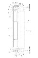
次に、図1、8を用いてプロセスカートリッジの組み立て手順について詳述する。まず、現像ユニットuの長手方向の両端部には、各端部部材81、82が設けられている。各端部部材81、82には、各揺動軸81b、82bが設けられている。各揺動軸81b、82bは、クリーニング枠体11に設けられた嵌合穴11eと、支持部材13に設けられた嵌合穴13とに各々嵌合する。これによって現像ユニットuは、クリーニング枠体11に揺動可能に支持される。
(Process cartridge assembly method)
Next, the assembly procedure of the process cartridge will be described in detail with reference to FIGS. First,
組み立ての際の手順を以下に示す。 The procedure for assembly is shown below.
i)感光体支持工程
まず、前記一端部において感光体ドラム1をクリーニング枠体11に回転可能に支持させる。
i) Photoreceptor Supporting Step First, the
ii)枠体支持工程I
クリーニング枠体11に対して図1に示す正規位置より長手方向他端部側に前記現像枠体をずらした位置において、前記現像枠体とクリーニング枠体11とを前記長手方向と交差する交差方向に互いに近づける。これにより、アーム81a、82aがクリーニング枠体11に設けられた凹部11p,11qに侵入する。
ii) Frame support process I
An intersecting direction in which the developing frame and the
iii)枠体支持工程II
次に、現像ユニットuを前記他端部から前記一端部へスライドさせる。これによって、前記一端部において、揺動軸81bがクリーニング枠体11の嵌合穴11eへ嵌合する。これによって、嵌合穴11eが揺動軸81bを揺動可能に支持する。そして、端部部材82に設けられた一時的被支持部としてのガイドボス86が、前記他端部において感光体ユニットvに設けられた一時的支持部としてのガイド穴11iに一時的に支持される。これにより現像ユニットuが感光体ユニットvに対する正規位置に移動する。即ち、支持部材13をクリーニング枠体11に取り付けるだけで、嵌合穴13cが揺動軸82bを、かつ、軸受部13hが軸部7a1を支持できるように、感光体ユニットvに対して現像ユニットuの位置決めがされる。ここで、他端揺動軸82bの揺動中心と同軸上にガイドボス86が設けられている。また、ガイドボス86の外径とガイド穴11iの内径との間隙(遊び)は、揺動軸81bの外径と嵌合穴11eの内径との間隙(遊び)よりも大きくしている。これにより、感光体ユニットvに現像ユニットuを支持させ易くしている。
iii) Frame support process II
Next, the developing unit u is slid from the other end to the one end. As a result, the
iv)支持部材取り付け工程
その後、前記他端部において、支持部材13をクリーニング枠体11に取付ける。この際、嵌合穴13cに揺動軸82bが嵌合する。即ち、前記他端部において、嵌合穴13cが揺動軸82bを揺動可能に支持する。そして、軸受部13hにドラムギア7aの軸部7a1が嵌合する。即ち、前記他端部において、軸受部13hが軸部7a1を回転可能に支持する。尚、支持部材13は、ビス止め、リモネン結合、樹脂結合等を用いてクリーニング枠体11固定される。ここで、ガイドボス86の外径とガイド穴11iの内径との間隙(遊び)は、揺動軸82bの外径と嵌合穴13cの内径との間隙(遊び)よりも大きくしている。これにより、ガイド穴11iにガイドボス86を支持させないようにして、かつ、嵌合穴13cに揺動軸82bを支持させることができる。ここで、揺動軸82bの外径と嵌合穴13cの内径との間隙は0の場合も含む。つまり、ガイドボス86とガイド穴11iは、支持部材13がクリーニング枠体13に取付けられるまでの前記現像枠体の外れ防止(組付け性向上)の機能を有する。そして、支持部材13がクリーニング枠体11に組付けられた際には、ガイドボス86とガイド穴11iは間隙を有して位置する。即ち、ガイドボス86がガイド穴11iを支持しているのが解除される。これによって、ガイドボス86とガイド穴11iは、支持部材13がクリーニング枠体13に取付けられるまで仮位置決めとしての機能を果たすことができる。即ち、ガイドボス86がガイド穴11iを一時的に支持する。この際、ガイドボス86及びガイド穴11iのいずれか一方に、又は双方にモルトプレーン等の弾性部材(不図示)を設けても良い。この場合は、揺動軸82bと嵌合穴13cとは接触した状態を保っているが、前述した仮位置決めとしての機能を果たすことができる。
iv) Support member attaching step Thereafter, the
一方、図9に示すように、支持部材13には、付勢バネ20が取付けられる。付勢バネ20は、感光体ユニットvに取付けられた保護シャッタ12を感光体ドラム7を保護する保護位置へ付勢する。本実施例では、付勢バネ20はねじりコイルバネである。そして、付勢バネ20は、支持部材13に設けられたボス13dと2つのバネ掛け部13e、13fに弾性力が蓄積された状態で取付けられる。そして、現像ユニットuが取付けられた状態のクリーニング枠体11に支持部材13が取付けられる。また、保護シャッタ12がクリーニングユニットuに対して回動可能に取付けられる。この状態で保護シャッタ12を感光体ドラム7を露出させる方向へ移動させる。これにより、保護シャッタ12のバネ掛け部12aが付勢バネ20に当接する。そして、付勢バネ20を支持部材13のバネ掛け13dから開放することにより保護シャッタ12が付勢される。また、バネ掛け部12aは付勢バネ20を長手中央方向へ移動させる方向に傾斜が設けられている。このため、保護シャッタ12の開閉動作で支持部材13のバネ掛け部13fから開放されることとなる。
On the other hand, as shown in FIG. 9, a biasing
(プロセスカートリッジの分解方法)
プロセスカートリッジBの分解方法について図11、12を用いて説明する。
(Process cartridge disassembly method)
A method for disassembling the process cartridge B will be described with reference to FIGS.
i)支持部材取り外し工程
本実施の形態においては、まず、支持部材13を感光体ユニットv(クリーニング枠体11)から取り外す。即ち、前記他端部において揺動軸82bから嵌合穴13cを離間させ、前記他端部において感光体ドラム7から軸受部13hを離間させる。これにより、ガイドボス86をガイド穴11iに係合させて、前記他端部において前記現像枠体をクリーニング枠体11に一時的に支持させた状態にする(即ち、現像枠体は前述した正規位置に位置する)。これによって、感光体ユニットv(クリーニング枠体11)と現像ユニットu(前記現像枠体)は取外し可能な状態になる。従って、クリーニング枠体11に対して支持部材13をビス止め等で取外し可能に構成した場合は、ビス等を外すことで容易に分解できる。一方、強度を要する場合等で、リモネン結合や樹脂結合を用いた場合は、図11に示す矢印部分近傍で、支持部材13が一体的に固定されたクリーニング枠体11を切断し、取り外す。これによって、クリーニング枠体11と前記現像枠体とが取外し可能となる。そして図12に示すように、感光体ドラム7、帯電ローラ8、クリーニングブレード11aの取外しも容易に可能となるよう構成されている。
i) Support Member Removal Step In the present embodiment, first, the
ii)枠体取り外し工程
次に、クリーニング枠体11に対して前記現像枠体を前記長手方向に沿って前記一端部から前記他端部へスライドさせる。これにより前記一端部において揺動軸81bを嵌合穴11eから離間させ、前記他端部においてガイドボス86をガイド穴11iから離間させる。そして(クリーニング枠体11)前記長手方向に対して交差する交差方向に向かって、現像ユニットu(前記現像枠体)を感光体ユニットvから取り外す。
ii) Frame body removal step Next, the developing frame body is slid from the one end portion to the other end portion along the longitudinal direction with respect to the
iii)感光体取り外し工程
その後、前記一端部において感光体ユニットuから感光体ドラム7を取り外す。
iii) Photoreceptor removing step Thereafter, the photoreceptor drum 7 is removed from the photoreceptor unit u at the one end.
以上説明したように、本実施例によれば、現像ユニットの長手両端部に設けられた揺動軸を、クリーニングユニットを構成するクリーニング枠体と支持部材とで揺動支持する。これにより、結合ピン等を用いることなくプロセスカートリッジを簡易に構成できる。また支持部材により現像ユニットの長手位置を決める。これにより、支持部材の取り外しにより容易にプロセスカートリッジが分解可能となる。 As described above, according to the present embodiment, the swinging shafts provided at both longitudinal ends of the developing unit are swingably supported by the cleaning frame body and the support member constituting the cleaning unit. Thereby, the process cartridge can be simply configured without using a coupling pin or the like. Further, the longitudinal position of the developing unit is determined by the support member. Thereby, the process cartridge can be easily disassembled by removing the support member.
本実施例によれば、現像手段を有する第二ユニットに設けられた被支持部を、電子写真感光体を有する第一ユニットと支持部材とで、回転可能に支持することができる。 According to this embodiment, the supported portion provided in the second unit having the developing means can be rotatably supported by the first unit having the electrophotographic photosensitive member and the support member.
また、本実施例によれば、部品点数を増やすことなく簡易な構成が可能となる。 Further, according to the present embodiment, a simple configuration can be achieved without increasing the number of parts.
また、本実施例によれば、支持部材を取り外すことにより、プロセスカートリッジの分解が可能であり、主要部品のリサイクル時の作業性が向上する。また、本実施例によれば結合ピン等を用いる必要がない。 Further, according to the present embodiment, the process cartridge can be disassembled by removing the support member, and the workability at the time of recycling the main parts is improved. Further, according to the present embodiment, there is no need to use a coupling pin or the like.
A 画像形成装置
B プロセスカートリッジ
G1、G2 本体ガイド
7 感光体ドラム
7a ドラムギア
8 帯電ローラ
10 現像容器
10d 現像ローラ
10e 現像ブレード
11 クリーニング枠体
11a クリーニングブレード
11e 嵌合穴
11f 第一被ガイド部
11g 第二被ガイド部
11i ガイド穴
11j 長手規制部
12 保護シャッタ
12a バネ掛け部
13 支持部材
13a 第三被ガイド部
13b 第四被ガイド部
13c 嵌合穴
13d ボス
13h 軸受部
13i アーム突き当て部
14 ドラム軸
20 付勢バネ
81 端部部材
82 アーム部
83 揺動軸
84 バネ掛け
85 圧縮コイルバネ
86 ガイドボス
u 現像ユニット
v クリーニングユニット
t 現像剤
A Image forming apparatus B Process cartridge G1, G2 Main body guide 7
Claims (12)
電子写真感光体と、An electrophotographic photoreceptor;
前記電子写真感光体に形成された静電潜像を現像するために現像剤を担持する現像剤担持体と、A developer carrying member for carrying a developer for developing the electrostatic latent image formed on the electrophotographic photosensitive member;
前記現像剤担持体の長手方向の一端部及び他端部を回転可能に支持する現像枠体であって、前記プロセスカートリッジの長手方向の一端側に一端被支持部と前記プロセスカートリッジの長手方向の他端側に他端被支持部を有する現像枠体と、A developing frame that rotatably supports one end and the other end in the longitudinal direction of the developer carrier, wherein one end supported portion and one end of the process cartridge in the longitudinal direction of the process cartridge A developing frame having the other end supported portion on the other end side;
前記一端側において前記電子写真感光体を回転可能に支持して、前記一端側において前記現像枠体を揺動可能に支持する感光体枠体であって、前記電子写真感光体を回転可能に支持する感光体支持部と、前記一端被支持部を揺動可能に支持するための一端支持部を有する感光体枠体と、A photosensitive member frame that rotatably supports the electrophotographic photosensitive member at the one end side and rotatably supports the developing frame at the one end side, and rotatably supports the electrophotographic photosensitive member. A photosensitive member supporting part, and a photosensitive member frame having an end supporting part for swingably supporting the one end supported part,
前記他端側において前記感光体枠体に取り付けられた支持部材であって、前記他端側において前記電子写真感光体を回転可能に支持する第二支持部を有して、前記他端側において前記現像枠体を揺動可能に支持するための第一支持部を有する支持部材と、A support member attached to the photoconductor frame on the other end side, and having a second support portion for rotatably supporting the electrophotographic photoconductor on the other end side; A support member having a first support portion for swingably supporting the developing frame;
を有し、Have
前記現像枠体は一時的被支持部を前記他端側に有し、前記感光体枠体は一時的支持部を前記他端側に有しており、前記プロセスカートリッジを組み立てるために前記感光体枠体に前記現像枠体を支持させた際に、前記一時的支持部は前記一時的被支持部を一時的に支持し、前記プロセスカートリッジを組み立てるために前記感光体枠体に前記現像枠体を支持させて前記感光体枠体に前記支持部材を取り付けた際に、前記一時的支持部に前記一時的被支持部を支持させないようにして、かつ、前記第一支持部に前記他端被支持部を支持させるために、前記一時的被支持部と前記一時的支持部との間の遊びは、前記他端被支持部と前記第一支持部との間の遊びよりも大きく構成されていることを特徴とするプロセスカートリッジ。The developing frame has a temporary supported portion on the other end side, and the photosensitive frame has a temporary supporting portion on the other end side, and the photoconductor for assembling the process cartridge. When the developing frame is supported by a frame, the temporary support portion temporarily supports the temporary supported portion, and the developing device frame is attached to the photosensitive frame to assemble the process cartridge. When the support member is attached to the photosensitive member frame body, the temporary support portion is not supported by the temporary support portion, and the first support portion is supported by the other end cover. In order to support the support portion, the play between the temporarily supported portion and the temporary support portion is configured to be larger than the play between the other end supported portion and the first support portion. A process cartridge characterized by comprising:
電子写真感光体と、An electrophotographic photoreceptor;
前記電子写真感光体に形成された静電潜像を現像するために現像剤を担持する現像剤担持体と、A developer carrying member for carrying a developer for developing the electrostatic latent image formed on the electrophotographic photosensitive member;
前記現像剤担持体の長手方向の一端部及び他端部を回転可能に支持する現像枠体であって、前記プロセスカートリッジの長手方向の一端側に一端被支持部と前記プロセスカートリッジの長手方向の他端側に他端被支持部を有する現像枠体と、A developing frame that rotatably supports one end and the other end in the longitudinal direction of the developer carrier, wherein one end supported portion and one end of the process cartridge in the longitudinal direction of the process cartridge A developing frame having the other end supported portion on the other end side;
前記一端側において前記電子写真感光体を回転可能に支持して、前記一端側において前記現像枠体を揺動可能に支持する感光体枠体であって、前記電子写真感光体を回転可能に支持する感光体支持部と、前記一端被支持部を揺動可能に支持するための一端支持部を有する感光体枠体と、A photosensitive member frame that rotatably supports the electrophotographic photosensitive member at the one end side and rotatably supports the developing frame at the one end side, and rotatably supports the electrophotographic photosensitive member. A photosensitive member supporting part, and a photosensitive member frame having an end supporting part for swingably supporting the one end supported part,
前記他端側において前記感光体枠体に取り付けられた支持部材であって、前記他端側において前記電子写真感光体を回転可能に支持する第二支持部を有して、前記他端側において前記現像枠体を揺動可能に支持するための第一支持部を有する支持部材と、A support member attached to the photoconductor frame on the other end side, and having a second support portion for rotatably supporting the electrophotographic photoconductor on the other end side; A support member having a first support portion for swingably supporting the developing frame;
を有し、Have
前記現像枠体は一時的被支持部を前記他端側に有し、前記感光体枠体は一時的支持部を前記他端側に有しており、前記プロセスカートリッジを分解するために前記プロセスカートリッジから前記支持部材を取り外した際に、前記一時的支持部は前記一時的被支持部を一時的に支持し、前記プロセスカートリッジを分解するために前記プロセスカートリッジから前記支持部材を取り外す前に、前記一時的支持部に前記一時的被支持部を支持させないようにして、かつ、前記第一支持部に前記他端被支持部を支持させるために、前記一時的被支持部と前記一時的支持部との間の遊びは、前記他端被支持部と前記第一支持部との間の遊びよりも大きく構成されていることを特徴とするプロセスカートリッジ。The developing frame has a temporary supported portion on the other end side, and the photosensitive frame has a temporary supporting portion on the other end side, and the process cartridge is disassembled to disassemble the process cartridge. When the support member is removed from the cartridge, the temporary support portion temporarily supports the temporary supported portion, and before removing the support member from the process cartridge in order to disassemble the process cartridge, The temporary supported portion and the temporary support so that the temporary supported portion is not supported by the temporary supported portion and the first supported portion is supported by the other end supported portion. The process cartridge is configured such that the play between the first and second support portions is larger than the play between the other-end supported portion and the first support portion.
前記一端側において前記現像枠体を前記感光体枠体に揺動可能に支持させて、前記他端側において前記現像枠体を前記感光体枠体に一時的に支持させる枠体支持工程と、
前記他端側において前記現像枠体を前記感光体枠体に支持させないようにして、かつ、前記他端側において前記現像枠体を前記支持部材に揺動可能に支持させるために、前記支持部材を前記感光体枠体に取り付ける支持部材取り付け工程と、
を有するプロセスカートリッジの組み立て方法。 A process cartridge that is detachable from an image forming apparatus , comprising: an electrophotographic photosensitive member; a developer carrying member that carries a developer for developing an electrostatic latent image formed on the electrophotographic photosensitive member; A developing frame for supporting one end and the other end in the longitudinal direction of the agent carrier , the one end being supported on one end in the longitudinal direction of the process cartridge and the other end in the longitudinal direction of the process cartridge A developing frame having a supported portion at the other end, a photosensitive member supporting portion for rotatably supporting the electrophotographic photosensitive member, and a photosensitive member having a one end supporting portion for swingably supporting the one end supported portion. A frame and a support member attached to the photoconductor frame on the other end side, and having a second support portion for rotatably supporting the electrophotographic photoconductor on the other end side, The developing frame on the other end side Comprises a support member having a first support portion for rotatably supporting the said developing frame are have a temporary supported portion at the other end, it said photosensitive member frame member includes a temporary supporting portion At the other end side, and when the developing device frame is supported by the photosensitive frame for assembling the process cartridge, the temporary support portion temporarily sets the temporary supported portion. When the developing frame is supported by the photoconductor frame and the support member is attached to the photoconductor frame to assemble the process cartridge, the temporary cover is attached to the temporary support portion. In order not to support the support portion and to allow the first support portion to support the other end supported portion, play between the temporary supported portion and the temporary support portion is the other Larger than the play between the end support part and the first support part In assembling method of a process cartridge has been,
A frame body supporting step in which the developing frame body is swingably supported on the one end side and swingable on the photosensitive body frame, and the developing frame body is temporarily supported on the photosensitive body frame on the other end side ;
It said development frame member so as not to be supported on said photosensitive member frame member at the other side, and said development frame member at the other side in order to swingably supported on said support member, said support member A support member attaching step for attaching the photoconductor frame to the photoconductor frame;
A process cartridge assembly method comprising:
前記支持部材取り付け工程において、前記他端部において前記電子写真感光体を前記支持部材に回転可能に支持させることを特徴とする請求項9に記載のプロセスカートリッジの組み立て方法。 Anda photoreceptor supporting step of rotatably supporting said electrophotographic photosensitive member to said photosensitive member frame member at the first end,
Wherein the supporting member mounting step, the assembling method of the process cartridge according to claim 9, wherein the benzalkonium the electrophotographic photosensitive member is rotatably supported by the supporting member at the other end.
前記他端側において前記現像枠体及び前記電子写真感光体から前記支持部材を離間させることにより、前記他端側において前記現像枠体を前記感光体枠体に一時的に支持させて、前記他端側において前記感光体枠体から前記支持部材を取り外す支持部材取り外し工程と、
前記一端側及び前記他端側において前記感光体枠体から前記現像枠体を取り外す枠体取り外し工程と、
を有すること特徴とするプロセスカートリッジの分解方法。 A process cartridge that is detachable from an image forming apparatus, comprising: an electrophotographic photosensitive member; a developer carrying member that carries a developer for developing an electrostatic latent image formed on the electrophotographic photosensitive member; A developing frame for supporting one end and the other end in the longitudinal direction of the agent carrier , the one end being supported on one end in the longitudinal direction of the process cartridge and the other end in the longitudinal direction of the process cartridge A developing device frame having a supported portion at the other end, a photoconductor frame that rotatably supports the electrophotographic photosensitive member on the one end side , and supports the developing frame on the one end side in a swingable manner; A support member attached to the photoconductor frame on the other end side, and having a second support portion for rotatably supporting the electrophotographic photoconductor on the other end side; The developing frame can be swung. A support member having a first support portion for supporting a possess the said developing frame has a temporary supported portion at the other end, said photosensitive member frame member includes a temporary supporting portion The temporary support part temporarily supports the temporary supported part when the support member is removed from the process cartridge in order to disassemble the process cartridge. Before removing the support member from the process cartridge in order to disassemble the process cartridge, the temporary support portion is not supported by the temporary support portion, and the first support portion is supported by the other end cover. In order to support the support portion, the play between the temporarily supported portion and the temporary support portion is configured to be larger than the play between the other end supported portion and the first support portion. process cartridge it is A decomposition method,
Wherein by separating the said supporting member from said development frame member and said electrophotographic photosensitive member at the other end, said the development frame member temporarily supported on said photosensitive member frame member at the other side, the other A support member removing step of removing the support member from the photoconductor frame on the end side ;
A frame removing step of removing the developing frame from the photoreceptor frame at the one end side and the other end side ;
A process cartridge disassembling method characterized by comprising:
Priority Applications (13)
| Application Number | Priority Date | Filing Date | Title |
|---|---|---|---|
| JP2007149155A JP5393001B2 (en) | 2006-06-26 | 2007-06-05 | Process cartridge, process cartridge assembly method, and disassembly method |
| US12/302,589 US8311449B2 (en) | 2006-06-26 | 2007-06-26 | Process cartridge, supporting member, process cartridge assembling method, and process cartridge disassembling method |
| BRPI0713379-0A BRPI0713379B1 (en) | 2006-06-26 | 2007-06-26 | PROCESSING CARTRIDGE, SUPPORTING MEMBER FOR USE WITH A PROCESSING CARTRIDGE, AND METHODS FOR ASSEMBLING AND DISASSEMBLING A PROCESSING CARTRIDGE |
| EP07745567.3A EP2041629B1 (en) | 2006-06-26 | 2007-06-26 | Process cartridge, supporting member, process cartridge assembling method, and process cartridge disassembling method |
| RU2009102235/28A RU2403604C2 (en) | 2006-06-26 | 2007-06-26 | Process cartridge, carrier element, method of assembling process cartridge and method of dismantling process cartridge |
| MYPI20085313 MY151786A (en) | 2006-06-26 | 2007-06-26 | Process cartridge, supporting member, process cartridge assembling method, and process cartridge disassembling method |
| KR1020087031711A KR101027877B1 (en) | 2006-06-26 | 2007-06-26 | Process cartridge, supporting member, process cartridge assembling method, and process cartridge disassembling method |
| PCT/JP2007/063200 WO2008001925A1 (en) | 2006-06-26 | 2007-06-26 | Process cartridge, supporting member, process cartridge assembling method, and process cartridge disassembling method |
| MX2008015773A MX2008015773A (en) | 2006-06-26 | 2007-06-26 | Process cartridge, supporting member, process cartridge assembling method, and process cartridge disassembling method. |
| CN201310073406.8A CN103149825B (en) | 2006-06-26 | 2007-06-26 | Handle box, support component, handle box assemble method and process cartridge disassembling method |
| CN2007800242901A CN101479674B (en) | 2006-06-26 | 2007-06-26 | Process cartridge, supporting member, process cartridge assembling method, and process cartridge disassembling method |
| TW096123105A TWI373695B (en) | 2006-06-26 | 2007-06-26 | Process cartridge, supporting member, process cartridge assembling method, and process cartridge disassembling method |
| HK13112362.0A HK1184865A1 (en) | 2006-06-26 | 2009-09-03 | Process cartridge, supporting member, process cartridge assembling method, and process cartridge disassembling method |
Applications Claiming Priority (3)
| Application Number | Priority Date | Filing Date | Title |
|---|---|---|---|
| JP2006175567 | 2006-06-26 | ||
| JP2006175567 | 2006-06-26 | ||
| JP2007149155A JP5393001B2 (en) | 2006-06-26 | 2007-06-05 | Process cartridge, process cartridge assembly method, and disassembly method |
Related Child Applications (1)
| Application Number | Title | Priority Date | Filing Date |
|---|---|---|---|
| JP2013111303A Division JP5559397B2 (en) | 2006-06-26 | 2013-05-27 | Process cartridge, support member, and process cartridge assembly method |
Publications (3)
| Publication Number | Publication Date |
|---|---|
| JP2008033271A JP2008033271A (en) | 2008-02-14 |
| JP2008033271A5 JP2008033271A5 (en) | 2010-07-15 |
| JP5393001B2 true JP5393001B2 (en) | 2014-01-22 |
Family
ID=38521084
Family Applications (1)
| Application Number | Title | Priority Date | Filing Date |
|---|---|---|---|
| JP2007149155A Expired - Fee Related JP5393001B2 (en) | 2006-06-26 | 2007-06-05 | Process cartridge, process cartridge assembly method, and disassembly method |
Country Status (12)
| Country | Link |
|---|---|
| US (1) | US8311449B2 (en) |
| EP (1) | EP2041629B1 (en) |
| JP (1) | JP5393001B2 (en) |
| KR (1) | KR101027877B1 (en) |
| CN (2) | CN103149825B (en) |
| BR (1) | BRPI0713379B1 (en) |
| HK (1) | HK1184865A1 (en) |
| MX (1) | MX2008015773A (en) |
| MY (1) | MY151786A (en) |
| RU (1) | RU2403604C2 (en) |
| TW (1) | TWI373695B (en) |
| WO (1) | WO2008001925A1 (en) |
Families Citing this family (21)
| Publication number | Priority date | Publication date | Assignee | Title |
|---|---|---|---|---|
| JP5393001B2 (en) * | 2006-06-26 | 2014-01-22 | キヤノン株式会社 | Process cartridge, process cartridge assembly method, and disassembly method |
| JP4440295B2 (en) * | 2007-10-31 | 2010-03-24 | キヤノン株式会社 | Process cartridge remanufacturing method |
| JP5344538B2 (en) * | 2008-05-27 | 2013-11-20 | キヤノン株式会社 | Process cartridge assembling method, process cartridge disassembling method, process cartridge remanufacturing method, and process cartridge |
| JP2011123348A (en) * | 2009-12-11 | 2011-06-23 | Canon Inc | Process cartridge and method for disassembling process cartridge |
| JP5503281B2 (en) * | 2009-12-25 | 2014-05-28 | キヤノン株式会社 | Developing device and process cartridge |
| JP5136582B2 (en) | 2010-03-24 | 2013-02-06 | ブラザー工業株式会社 | Developer cartridge |
| US9063472B2 (en) * | 2011-03-17 | 2015-06-23 | Ricoh Company, Limited | Image forming apparatus and belt tensioning unit |
| CN102262376A (en) * | 2011-08-02 | 2011-11-30 | 珠海天威飞马打印耗材有限公司 | Developer assembly and development box |
| JP5975823B2 (en) | 2012-09-28 | 2016-08-23 | キヤノン株式会社 | Cartridge and image forming apparatus |
| JP6004176B2 (en) * | 2012-10-10 | 2016-10-05 | 村田機械株式会社 | Recording device |
| JP6138181B2 (en) | 2014-04-15 | 2017-05-31 | キヤノン株式会社 | Resin molded product and cartridge used for image forming apparatus, method for manufacturing movable member used for image forming apparatus, and method for manufacturing cartridge |
| US9285758B1 (en) * | 2014-12-19 | 2016-03-15 | Lexmark International, Inc. | Positional control features between replaceable units of an electrophotographic image forming device |
| JP6602126B2 (en) * | 2015-09-16 | 2019-11-06 | キヤノン株式会社 | Cartridge and member used for cartridge |
| JP7058992B2 (en) | 2017-12-13 | 2022-04-25 | キヤノン株式会社 | Image forming equipment and cartridge |
| CN116184782A (en) | 2017-12-13 | 2023-05-30 | 佳能株式会社 | Cartridge and image forming apparatus |
| US10627780B2 (en) | 2018-01-23 | 2020-04-21 | Canon Kabushiki Kaisha | Cartridge and image forming apparatus |
| JP7057191B2 (en) | 2018-03-30 | 2022-04-19 | キヤノン株式会社 | Manufacturing method of image-carrying unit and manufacturing method of cartridge |
| JP7059072B2 (en) | 2018-03-30 | 2022-04-25 | キヤノン株式会社 | Manufacturing method of image-carrying unit and manufacturing method of cartridge |
| US11086267B2 (en) * | 2018-09-25 | 2021-08-10 | Canon Kabushiki Kaisha | Image forming apparatus and developing cartridge |
| JP7494069B2 (en) | 2020-09-16 | 2024-06-03 | キヤノン株式会社 | Cartridge and method for disassembling cartridge |
| JP2023057884A (en) | 2021-10-12 | 2023-04-24 | キヤノン株式会社 | process cartridge |
Family Cites Families (15)
| Publication number | Priority date | Publication date | Assignee | Title |
|---|---|---|---|---|
| JPS62187376A (en) * | 1986-02-13 | 1987-08-15 | Konishiroku Photo Ind Co Ltd | Recorder |
| SG43303A1 (en) | 1991-04-10 | 1997-10-17 | Canon Kk | Process cartridge recording apparatus and method for assembling process cartridge |
| JPH08152781A (en) | 1994-11-25 | 1996-06-11 | Ricoh Co Ltd | Image forming device |
| JP3397590B2 (en) | 1996-07-04 | 2003-04-14 | キヤノン株式会社 | Process cartridge assembling method, process cartridge, and electrophotographic image forming apparatus |
| JPH09120251A (en) | 1996-10-11 | 1997-05-06 | Canon Inc | Process cartridge, recording device and assembly of process cartridge |
| JP3320399B2 (en) * | 1999-05-20 | 2002-09-03 | キヤノン株式会社 | Process cartridge, method of assembling process cartridge, and electrophotographic image forming apparatus |
| JP3564080B2 (en) * | 2001-04-27 | 2004-09-08 | キヤノン株式会社 | Process cartridge remanufacturing method |
| JP3840063B2 (en) * | 2001-04-27 | 2006-11-01 | キヤノン株式会社 | Process cartridge |
| JP2003307931A (en) | 2002-04-17 | 2003-10-31 | Canon Inc | Process cartridge and electrophotographic image forming apparatus |
| JP2004117697A (en) | 2002-09-25 | 2004-04-15 | Canon Inc | Image forming apparatus, process cartridge and electrode member |
| JP3542588B2 (en) * | 2002-09-30 | 2004-07-14 | キヤノン株式会社 | Developing cartridge, mounting method of one end side cover, mounting method of other end side cover, and electrophotographic image forming apparatus |
| JP2004317995A (en) | 2003-04-21 | 2004-11-11 | Canon Inc | Toner seal member and process cartridge |
| JP4250555B2 (en) | 2004-03-09 | 2009-04-08 | キヤノン株式会社 | Electrophotographic image forming apparatus and spacing member |
| JP2006058705A (en) * | 2004-08-20 | 2006-03-02 | Ricoh Co Ltd | Process cartridge and image forming apparatus having the same |
| JP5393001B2 (en) * | 2006-06-26 | 2014-01-22 | キヤノン株式会社 | Process cartridge, process cartridge assembly method, and disassembly method |
-
2007
- 2007-06-05 JP JP2007149155A patent/JP5393001B2/en not_active Expired - Fee Related
- 2007-06-26 WO PCT/JP2007/063200 patent/WO2008001925A1/en active Application Filing
- 2007-06-26 MY MYPI20085313 patent/MY151786A/en unknown
- 2007-06-26 EP EP07745567.3A patent/EP2041629B1/en active Active
- 2007-06-26 BR BRPI0713379-0A patent/BRPI0713379B1/en active IP Right Grant
- 2007-06-26 CN CN201310073406.8A patent/CN103149825B/en active Active
- 2007-06-26 MX MX2008015773A patent/MX2008015773A/en active IP Right Grant
- 2007-06-26 US US12/302,589 patent/US8311449B2/en active Active
- 2007-06-26 TW TW096123105A patent/TWI373695B/en not_active IP Right Cessation
- 2007-06-26 RU RU2009102235/28A patent/RU2403604C2/en active
- 2007-06-26 CN CN2007800242901A patent/CN101479674B/en not_active Expired - Fee Related
- 2007-06-26 KR KR1020087031711A patent/KR101027877B1/en active IP Right Grant
-
2009
- 2009-09-03 HK HK13112362.0A patent/HK1184865A1/en not_active IP Right Cessation
Also Published As
| Publication number | Publication date |
|---|---|
| CN101479674B (en) | 2013-04-10 |
| KR20090018168A (en) | 2009-02-19 |
| MX2008015773A (en) | 2009-01-12 |
| MY151786A (en) | 2014-07-14 |
| US8311449B2 (en) | 2012-11-13 |
| WO2008001925A1 (en) | 2008-01-03 |
| US20090238603A1 (en) | 2009-09-24 |
| BRPI0713379A2 (en) | 2012-03-20 |
| RU2009102235A (en) | 2010-08-10 |
| CN103149825B (en) | 2016-02-03 |
| HK1184865A1 (en) | 2014-01-30 |
| RU2403604C2 (en) | 2010-11-10 |
| TW200817850A (en) | 2008-04-16 |
| EP2041629A1 (en) | 2009-04-01 |
| EP2041629B1 (en) | 2019-09-04 |
| CN103149825A (en) | 2013-06-12 |
| TWI373695B (en) | 2012-10-01 |
| JP2008033271A (en) | 2008-02-14 |
| KR101027877B1 (en) | 2011-04-07 |
| CN101479674A (en) | 2009-07-08 |
| BRPI0713379B1 (en) | 2019-09-17 |
Similar Documents
| Publication | Publication Date | Title |
|---|---|---|
| JP5393001B2 (en) | Process cartridge, process cartridge assembly method, and disassembly method | |
| EP2721448B1 (en) | Process cartridge, electrophotographic image forming apparatus, and assembly method of process cartridge | |
| US7890025B2 (en) | Process cartridge and image forming apparatus including drum and shaft coupling members transmitting driving forces to a photosensitive drum and a developing roller, respectively | |
| US10353339B2 (en) | Cartridge with restriction member for restricting relative movement of toner cartridge and process cartridge | |
| EP1843216B1 (en) | Method of mounting a photosensitive drum for printer cartridge | |
| JP2009109848A (en) | Reproduction method for process cartridge | |
| JP2012088689A (en) | Cartridge and image forming apparatus | |
| EP1316852B1 (en) | Developing device, process cartridge and image forming apparatus using pressure between developing roller and photosensitive drum independently from the amount of developer in a toner container | |
| US20160231698A1 (en) | Main body of image forming apparatus | |
| JPH10240102A (en) | Process cartridge | |
| JP5901692B2 (en) | Process cartridge, support member, process cartridge assembly method, and disassembly method | |
| JP2011191560A (en) | Cleaning device, cartridge and image forming apparatus | |
| JP7305717B2 (en) | cartridge unit | |
| JP5522993B2 (en) | Process cartridge | |
| JP4856891B2 (en) | Developing roller, developing device, and process cartridge | |
| JP2006349936A (en) | Process cartridge | |
| JPH11184353A (en) | Process cartridge and electrophotographic image forming device | |
| JP2003131542A (en) | Process cartridge and electrophotographic image forming device | |
| JPH11311934A (en) | Process cartridge and electrophotographic image forming device | |
| JPH08305249A (en) | Process cartridge and image forming device | |
| JP2000098856A (en) | Process cartridge and electrophotographic image forming device | |
| JP2000356939A (en) | Process cartridge and image forming device | |
| JP2002311756A (en) | Electrophotographic photoreceptor unit, process cartridge and electrophotographic image forming device | |
| JP2001042752A (en) | Processing cartridge |
Legal Events
| Date | Code | Title | Description |
|---|---|---|---|
| RD04 | Notification of resignation of power of attorney |
Free format text: JAPANESE INTERMEDIATE CODE: A7424 Effective date: 20100201 |
|
| A521 | Request for written amendment filed |
Free format text: JAPANESE INTERMEDIATE CODE: A523 Effective date: 20100528 |
|
| A621 | Written request for application examination |
Free format text: JAPANESE INTERMEDIATE CODE: A621 Effective date: 20100528 |
|
| RD01 | Notification of change of attorney |
Free format text: JAPANESE INTERMEDIATE CODE: A7421 Effective date: 20100630 |
|
| A131 | Notification of reasons for refusal |
Free format text: JAPANESE INTERMEDIATE CODE: A131 Effective date: 20130326 |
|
| A521 | Request for written amendment filed |
Free format text: JAPANESE INTERMEDIATE CODE: A523 Effective date: 20130527 |
|
| TRDD | Decision of grant or rejection written | ||
| A01 | Written decision to grant a patent or to grant a registration (utility model) |
Free format text: JAPANESE INTERMEDIATE CODE: A01 Effective date: 20130917 |
|
| A61 | First payment of annual fees (during grant procedure) |
Free format text: JAPANESE INTERMEDIATE CODE: A61 Effective date: 20131015 |
|
| LAPS | Cancellation because of no payment of annual fees |