JP4250555B2 - Electrophotographic image forming apparatus and spacing member - Google Patents
Electrophotographic image forming apparatus and spacing member Download PDFInfo
- Publication number
- JP4250555B2 JP4250555B2 JP2004066364A JP2004066364A JP4250555B2 JP 4250555 B2 JP4250555 B2 JP 4250555B2 JP 2004066364 A JP2004066364 A JP 2004066364A JP 2004066364 A JP2004066364 A JP 2004066364A JP 4250555 B2 JP4250555 B2 JP 4250555B2
- Authority
- JP
- Japan
- Prior art keywords
- unit
- electrical contact
- main body
- image forming
- forming apparatus
- Prior art date
- Legal status (The legal status is an assumption and is not a legal conclusion. Google has not performed a legal analysis and makes no representation as to the accuracy of the status listed.)
- Expired - Lifetime
Links
- 238000000926 separation method Methods 0.000 claims description 82
- 238000000034 method Methods 0.000 claims description 52
- 239000000758 substrate Substances 0.000 claims description 4
- 230000015572 biosynthetic process Effects 0.000 claims 2
- 101100545272 Caenorhabditis elegans zif-1 gene Proteins 0.000 description 37
- 239000000463 material Substances 0.000 description 11
- 238000012546 transfer Methods 0.000 description 8
- 238000004140 cleaning Methods 0.000 description 6
- 238000003860 storage Methods 0.000 description 6
- 238000003780 insertion Methods 0.000 description 5
- 230000037431 insertion Effects 0.000 description 5
- 238000012856 packing Methods 0.000 description 5
- 238000011161 development Methods 0.000 description 4
- 238000004806 packaging method and process Methods 0.000 description 4
- 108091008695 photoreceptors Proteins 0.000 description 3
- 230000005489 elastic deformation Effects 0.000 description 2
- 230000006870 function Effects 0.000 description 2
- 238000012423 maintenance Methods 0.000 description 2
- 239000002184 metal Substances 0.000 description 2
- 230000004308 accommodation Effects 0.000 description 1
- 239000011247 coating layer Substances 0.000 description 1
- 238000004891 communication Methods 0.000 description 1
- 230000008878 coupling Effects 0.000 description 1
- 238000010168 coupling process Methods 0.000 description 1
- 238000005859 coupling reaction Methods 0.000 description 1
- 238000000605 extraction Methods 0.000 description 1
- 239000004744 fabric Substances 0.000 description 1
- 238000009434 installation Methods 0.000 description 1
- 239000010410 layer Substances 0.000 description 1
- WABPQHHGFIMREM-UHFFFAOYSA-N lead(0) Chemical compound [Pb] WABPQHHGFIMREM-UHFFFAOYSA-N 0.000 description 1
- 238000004519 manufacturing process Methods 0.000 description 1
- 230000002093 peripheral effect Effects 0.000 description 1
- 238000003825 pressing Methods 0.000 description 1
- 239000011347 resin Substances 0.000 description 1
- 229920005989 resin Polymers 0.000 description 1
- 238000003756 stirring Methods 0.000 description 1
- 239000002699 waste material Substances 0.000 description 1
Images


Classifications
-
- A—HUMAN NECESSITIES
- A63—SPORTS; GAMES; AMUSEMENTS
- A63H—TOYS, e.g. TOPS, DOLLS, HOOPS OR BUILDING BLOCKS
- A63H33/00—Other toys
- A63H33/04—Building blocks, strips, or similar building parts
- A63H33/046—Building blocks, strips, or similar building parts comprising magnetic interaction means, e.g. holding together by magnetic attraction
-
- G—PHYSICS
- G03—PHOTOGRAPHY; CINEMATOGRAPHY; ANALOGOUS TECHNIQUES USING WAVES OTHER THAN OPTICAL WAVES; ELECTROGRAPHY; HOLOGRAPHY
- G03G—ELECTROGRAPHY; ELECTROPHOTOGRAPHY; MAGNETOGRAPHY
- G03G21/00—Arrangements not provided for by groups G03G13/00 - G03G19/00, e.g. cleaning, elimination of residual charge
- G03G21/16—Mechanical means for facilitating the maintenance of the apparatus, e.g. modular arrangements
- G03G21/1642—Mechanical means for facilitating the maintenance of the apparatus, e.g. modular arrangements for connecting the different parts of the apparatus
- G03G21/1652—Electrical connection means
-
- B—PERFORMING OPERATIONS; TRANSPORTING
- B21—MECHANICAL METAL-WORKING WITHOUT ESSENTIALLY REMOVING MATERIAL; PUNCHING METAL
- B21D—WORKING OR PROCESSING OF SHEET METAL OR METAL TUBES, RODS OR PROFILES WITHOUT ESSENTIALLY REMOVING MATERIAL; PUNCHING METAL
- B21D51/00—Making hollow objects
- B21D51/02—Making hollow objects characterised by the structure of the objects
- B21D51/08—Making hollow objects characterised by the structure of the objects ball-shaped objects
-
- G—PHYSICS
- G03—PHOTOGRAPHY; CINEMATOGRAPHY; ANALOGOUS TECHNIQUES USING WAVES OTHER THAN OPTICAL WAVES; ELECTROGRAPHY; HOLOGRAPHY
- G03G—ELECTROGRAPHY; ELECTROPHOTOGRAPHY; MAGNETOGRAPHY
- G03G21/00—Arrangements not provided for by groups G03G13/00 - G03G19/00, e.g. cleaning, elimination of residual charge
- G03G21/16—Mechanical means for facilitating the maintenance of the apparatus, e.g. modular arrangements
- G03G21/18—Mechanical means for facilitating the maintenance of the apparatus, e.g. modular arrangements using a processing cartridge, whereby the process cartridge comprises at least two image processing means in a single unit
- G03G21/1839—Means for handling the process cartridge in the apparatus body
- G03G21/1867—Means for handling the process cartridge in the apparatus body for electrically connecting the process cartridge to the apparatus, electrical connectors, power supply
-
- G—PHYSICS
- G09—EDUCATION; CRYPTOGRAPHY; DISPLAY; ADVERTISING; SEALS
- G09B—EDUCATIONAL OR DEMONSTRATION APPLIANCES; APPLIANCES FOR TEACHING, OR COMMUNICATING WITH, THE BLIND, DEAF OR MUTE; MODELS; PLANETARIA; GLOBES; MAPS; DIAGRAMS
- G09B19/00—Teaching not covered by other main groups of this subclass
Landscapes
- Engineering & Computer Science (AREA)
- Physics & Mathematics (AREA)
- General Physics & Mathematics (AREA)
- Business, Economics & Management (AREA)
- Computer Vision & Pattern Recognition (AREA)
- Mechanical Engineering (AREA)
- Entrepreneurship & Innovation (AREA)
- Educational Administration (AREA)
- Educational Technology (AREA)
- Theoretical Computer Science (AREA)
- Electrophotography Configuration And Component (AREA)
Description
本発明はユニットを着脱可能な電子写真画像形成装置及びそれらに用いる離間部材に関
するものである。
The present invention relates to an electrophotographic image forming apparatus to which a unit can be attached and detached and a separation member used for them.
従来、電子写真画像形成プロセスを用いて記録媒体に画像形成する電子写真画像形成装置においては、電子写真感光体及び前記電子写真感光体に作用するプロセス手段を一体的にカートリッジ化して、このカートリッジを電子写真画像形成装置本体に着脱可能とするカートリッジ方式が採用されている。このカートリッジ方式によれば、装置のメンテナンスをサービスマンによらずにユーザ自身で行うことができるので、格段に操作性を向上させることができる。そのため、このカートリッジ方式は、電子写真画像形成装置において広く用いられている。 Conventionally, in an electrophotographic image forming apparatus for forming an image on a recording medium using an electrophotographic image forming process, an electrophotographic photosensitive member and process means acting on the electrophotographic photosensitive member are integrally formed into a cartridge, and this cartridge is A cartridge system that can be attached to and detached from the electrophotographic image forming apparatus main body is employed. According to this cartridge system, the maintenance of the apparatus can be performed by the user himself / herself without depending on the service person, so that the operability can be remarkably improved. For this reason, this cartridge system is widely used in electrophotographic image forming apparatuses.
こうした電子写真画像形成装置においては、カートリッジの電子写真感光体(以下、感光体)を帯電するための帯電手段や、現像手段などに電圧を印加する必要がある。 In such an electrophotographic image forming apparatus, it is necessary to apply a voltage to a charging unit for charging an electrophotographic photosensitive member (hereinafter referred to as a photosensitive member) of a cartridge, a developing unit, or the like.
このため電子写真画像形成装置においては、カートリッジを電子写真画像形成装置本体に装着すると、本体電気接点とカートリッジ電気接点が接触することによって電気的に接続される。そして画像形成装置本体からカートリッジに電圧が印加される。 For this reason, in the electrophotographic image forming apparatus, when the cartridge is mounted on the main body of the electrophotographic image forming apparatus, the main body electrical contacts and the cartridge electrical contacts are electrically connected to each other. A voltage is applied to the cartridge from the image forming apparatus main body.
また、近年種々のサービス情報やプロセス情報を記憶するメモリ(記憶素子)をカートリッジに搭載した製品が実現されている。電子写真画像形成装置はこのカートリッジのメモリ情報を活用することにより、画質やカートリッジのメンテナンスをより一層向上させている。そして、電子写真画像形成装置本体に設けられたコネクタとの間で電気的接続を行う。これにより、カートリッジのメモリと電気通信を行っているものがある。 In recent years, products in which a memory (storage element) that stores various service information and process information is mounted on a cartridge have been realized. The electrophotographic image forming apparatus further improves image quality and cartridge maintenance by utilizing the memory information of the cartridge. Then, an electrical connection is made with a connector provided in the electrophotographic image forming apparatus main body. Thus, some are in electrical communication with the cartridge memory.
このように、電子写真画像形成装置とプロセスカートリッジとの間には種々の電気接点が設けられている。そのため、運搬中の電気接点同士の摩耗や変形を防ぐため、一般的には、電子写真画像形成装置本体にプロセスカートリッジを装着せずに、電子写真画像形成装置とプロセスカートリッジを別々に梱包する場合が多い。そのため、一つの梱包箱内に装置本体とカートリッジが別々に梱包された状態で運搬される。そのため梱包箱が大きくなり、運搬コストが高くなる。 As described above, various electrical contacts are provided between the electrophotographic image forming apparatus and the process cartridge. Therefore, in order to prevent wear and deformation of electrical contacts during transportation, in general, when the electrophotographic image forming apparatus and the process cartridge are packed separately without attaching the process cartridge to the main body of the electrophotographic image forming apparatus. There are many. Therefore, the apparatus main body and the cartridge are conveyed separately in a single packing box. Therefore, a packing box becomes large and a conveyance cost becomes high.
そこで、特許文献1には、画像形成部から搬送されたシートを収容するシート収容空間に、トナーカートリッジを梱包した状態で挿入配置した画像形成装置の梱包具について開示されている。 In view of this, Japanese Patent Application Laid-Open No. H10-228688 discloses a packaging tool for an image forming apparatus in which a toner cartridge is inserted and arranged in a sheet accommodation space that accommodates a sheet conveyed from an image forming unit.
しかしながら、上記特許文献1に開示された技術では、トナーカートリッジを画像形成装置のシート収容部内に挿入して装着するための梱包具を必要とする。また、画像形成装置の外側にシートが排出される画像形成装置や、前記シート収容空間がトナーカートリッジよりも狭い画像形成装置の場合についてはこの技術は適用することができない。
本発明は上記従来技術を鑑みなされたものである。 The present invention has been made in view of the above prior art.
本発明の目的は、電子写真画像形成装置本体内にユニットを装着したままの状態で、電子写真画像形成装置を運搬することである。
An object of the present invention, in a state of mounting the unit to the electrophotographic image forming apparatus main body, and to carry the electrophotographic image forming apparatus.
本発明の他の目的は、ユニットと電子写真画像形成装置の運搬効率を高めることである。
Another object of the present invention is to increase the transport efficiency of the unit and an electrophotographic image forming apparatus.
本発明の他の目的は、電子写真画像形成装置本体にユニットを装着した状態であっても、ユニットに設けられた電気接点と、装置本体に設けられた電気接点を離間させることである。
Another object of the present invention, even in a state of mounting the unit to the main assembly of an electrophotographic image forming apparatus is to spaced electrical contacts provided on the unit, the electrical contact points provided on the apparatus main body.
また、本発明の他の目的は、電子写真画像形成装置本体内にユニットを装着した状態で運搬した際に、電気接点の損傷を防止することである。
Another object of the present invention, upon carrying while wearing the unit to the electrophotographic image forming apparatus main body, and to prevent damage to the electrical contacts.
上記目標を達成するために、本発明における代表的な構成は、
記録媒体に画像を形成する電子写真画像形成装置であって、ユニットを装着した状態で運搬可能な電子写真画像形成装置において、
(i)前記電子写真画像形成装置の装置本体に移動可能に設けられた可動部材と、
(ii)前記可動部材に設けられた本体電気接点と、
(iii)前記ユニットを取り外し可能に装着する装着部と、
(iv)前記装着部に装着された前記ユニットであって、前記ユニットが前記装置本体に装着されて、前記記録媒体に画像を形成する画像形成時において、前記本体電気接点と接触可能なユニット電気接点を有する前記ユニットと、
(v)前記ユニットを装着した状態で前記電子写真画像形成装置を運搬する際に、前記可動部材及び前記ユニットと当接することで、前記本体電気接点と前記ユニット電気接点との間に隙間を設けて、前記本体電気接点と前記ユニット電気接点とを離間させる離間部材と、
を有することを特徴とする電子写真画像形成装置である。
In order to achieve the above goal, a typical configuration in the present invention is:
An electrophotographic image forming apparatus for forming an image on a recording medium, wherein the electrophotographic image forming apparatus can be transported in a state where the unit is mounted.
(I) a movable member movably provided in the main body of the electrophotographic image forming apparatus;
(Ii) a main body electrical contact provided on the movable member;
(Iii) a mounting portion for detachably mounting the unit;
(Iv) The unit mounted on the mounting unit, wherein the unit is mounted on the apparatus main body and can be brought into contact with the main body electrical contact when forming an image on the recording medium. The unit having contacts;
(V) When transporting the electrophotographic image forming apparatus with the unit mounted, a gap is formed between the main body electrical contact and the unit electrical contact by contacting the movable member and the unit. A separating member for separating the main body electrical contact and the unit electrical contact;
An electrophotographic image forming apparatus comprising:
本発明によれば、電子写真画像形成装置本体にユニットを装着した状態であっても、ユニットに設けられた電気接点と、装置本体に設けられた電気接点を離間することができる。
According to the present invention, even when the unit is mounted on the electrophotographic image forming apparatus main body, the electrical contact provided on the unit and the electrical contact provided on the apparatus main body can be separated.
また、電子写真画像形成装置本体内にユニットを装着した状態で電子写真画像形成装置本体を運搬した際に電気接点の破損を防止することができる。そして、ユニットを梱包する梱包箱を別途必要としないから運搬効率を上げることができる。 Further, when the electrophotographic image forming apparatus main body is transported with the unit mounted in the electrophotographic image forming apparatus main body, it is possible to prevent the electrical contacts from being damaged. And since the packaging box which packs a unit is not required separately, conveyance efficiency can be raised.
以下に図面及び実施例を参照して、この発明を実施するための最良の形態を例示的に詳しく説明する。ただし、この実施例に記載されている構成部品の大きさ、材質、形状、機能、その相対配置などは、特に特定的な記載がない限りは、この発明の範囲をそれらのみに限定する趣旨のものではない。また、以下の説明で一度説明した部材についての材質、形状などは、特に改めて記載しない限り初めの説明と同様のものである。 The best mode for carrying out the present invention will be exemplarily described in detail below with reference to the drawings and embodiments. However, the size, material, shape, function, relative arrangement, etc. of the components described in this embodiment are intended to limit the scope of the present invention only to those unless otherwise specified. It is not a thing. Further, the materials, shapes, etc. of the members once described in the following description are the same as those in the first description unless otherwise described.
本発明の実施例1について図面に基づいて説明する。
(電子写真画像形成装置及びプロセスカートリッジの構成)
プロセスカートリッジを装置本体に着脱可能に装着する電子写真画像形成装置の全体構成及びプロセスカートリッジ構成について図3及び図4を参照して説明する。
(Configuration of electrophotographic image forming apparatus and process cartridge)
The overall configuration of the electrophotographic image forming apparatus in which the process cartridge is detachably attached to the apparatus main body and the process cartridge configuration will be described with reference to FIGS.
図3は電子写真画像形成装置の一例であるレーザビームプリンタの概略構成断面図、図4はレーザビームプリンタに着脱可能なプロセスカートリッジ及び電気接点の概略構成断面図である。 3 is a schematic sectional view of a laser beam printer as an example of an electrophotographic image forming apparatus, and FIG. 4 is a schematic sectional view of a process cartridge and electrical contacts that can be attached to and detached from the laser beam printer.
まず、シート材Sの流れに沿って概略的な構成を説明する。レーザビームプリンタ(以下、装置本体と称す)Eは電子写真方式によって画像を形成し、搬送手段によってシート材Sを画像形成部2へ搬送してトナー画像を転写する。そして、そのシート材Sを定着手段へ搬送してトナー画像をシート材Sに定着した後、排出部へと排出する。
First, a schematic configuration will be described along the flow of the sheet material S. A laser beam printer (hereinafter referred to as an apparatus main body) E forms an image by an electrophotographic method, conveys a sheet material S to an
具体的には、装置本体Eの下部にシート材Sを積載収納するカセット111が装着されている。カセット111内に積載収納されているシート材Sが、反時計回り方向に回転する給送ローラ112によって最上位のシートから順に繰り出され、搬送ローラ対113、114により画像形成部2に送られる。
Specifically, a
画像形成部2ではレーザスキャナ121によって、画像情報に応じたレーザー光が回転している感光体151上に照射される。そして、感光体151に静電潜像が形成される。この静電潜像はプロセスカートリッジ(以下、カートリッジと称す)P内の現像部にてトナーにより現像される。
In the
現像部2にて現像された画像は転写ローラ124によりシート材Sに転写される。そして、定着部3に送られる。定着部3を通過して定着処理を終えたシート材Sは搬送ローラ対133により排出部へ排出される。
The image developed by the developing
なお、図3に示す電装部4は、装置の電源部及び装置を制御する制御基板を有する。 3 includes a power supply unit of the apparatus and a control board that controls the apparatus.
カートリッジPは、回転可能に支持する感光体151と、その表面に電圧を印加することで感光体151の表面を一様に帯電する帯電手段としての帯電ローラ152とを有する。
The cartridge P includes a
装置本体Eに設けられた電装部4で発生した電圧は、本体帯電接点125を介して、カートリッジPに設けられたカートリッジ帯電接点153、帯電ローラ152へと給電される。次いでレーザスキャナ121からの画像情報に応じたレーザー光を感光体151へ照射して潜像を形成する。そしてこの潜像をトナーを用いて現像手段によって現像する。
The voltage generated in the
さらに説明すると、帯電ローラ152は感光体151に接触して設けられており、感光体151の帯電を行う。この帯電ローラ152は、感光体151に対して従動回転する。また、現像手段は、感光体151の現像領域へトナーを供給して、感光体151に形成された潜像を現像する。
More specifically, the
上記現像手段は、トナー収納容器154内のトナーを攪拌部材155の回転によって現像室156に送り出す。そして、マグネットローラ(固定磁石)を内蔵した現像ローラ157を回転させるとともに、現像ブレード158によって摩擦帯電電荷を付与したトナー層を現像ローラ157の表面に形成する。そして、現像ローラ157に電圧印加し、現像ローラ上のトナーを潜像に応じて感光体151へ転移させる。これによってトナー像を形
成して現像を行う。電圧は前記電装部4より現像接点126を介して、カートリッジPに設けられたカートリッジ現像接点165、現像ローラ157へと給電される。
The developing unit sends the toner in the
現像ブレード158は、現像ローラ157の周面上のトナー量を規定すると共に摩擦帯電電荷を付与する。
The developing
転写ローラ124によってトナー画像をシート材Sに転写した後の感光体151は、クリーニング手段によって感光体151上に残留したトナーを除去される。そして次の画像形成プロセスに供される。クリーニング手段は、感光体151に当接して設けられた弾性クリーニングブレード159によって感光体151上の残留トナーを掻き落として廃トナー溜め160へと集める。
After the toner image is transferred to the sheet material S by the
カートリッジPの表面には情報記憶媒体であるメモリタグ6が取り付けられている。そしてこのメモリタグ6は装置本体に設けられた側のコネクタ7に設けられている本体電気接点72(第1電気接点)と電気的接続を行う。そして装置本体Eと通信を行う。
A
ドラムシャッタ161はカートリッジP非装着時にはドラム保護のために閉じた状態であり、装置本体Eに装着されると開いた状態となる(図3、図4参照)。
The
次にプロセスカートリッジ枠体について説明する。 Next, the process cartridge frame will be described.
図4に示すように、感光体151、帯電ローラ152及び弾性クリーニングブレード159は、カートリッジ枠体の一つであるドラム枠体162に取り付けられ、一体的な感光体ユニット100を構成している。
As shown in FIG. 4, the
一方、現像ユニット200は、トナーを収容しているトナー収納容器154と、現像ローラ157や現像ブレード158を保持する現像枠体164とにより構成されている。
On the other hand, the developing
そして、感光体ユニット100と現像手段ユニット200をピン結合(不図示)によって互いに回動可能に結合することによってカートリッジPを構成する。
The
(プロセスカートリッジの着脱構成及び装着部)
カートリッジPの着脱ガイド、装着部構成について図5〜図10を参照して説明する。図5はプロセスカートリッジ着脱の際にカートリッジアクセスドアを開けた状態の装置本体概略斜視図、図6、図7は装置本体のプロセスカートリッジ装着手段部斜視図、図8、図9はプロセスカートリッジ略斜視図、図10はプロセスカートリッジ装着・取り出し軌跡説明図である。
(Process cartridge mounting and dismounting part)
The mounting / demounting guide and mounting portion configuration of the cartridge P will be described with reference to FIGS. 5 is a schematic perspective view of the apparatus main body with the cartridge access door opened when the process cartridge is attached / detached, FIGS. 6 and 7 are perspective views of the process cartridge mounting means of the apparatus main body, and FIGS. 8 and 9 are schematic perspective views of the process cartridge. FIG. 10 and FIG. 10 are explanatory views of a process cartridge loading / unloading locus.
図5に示すように、カートリッジPは装置本体EのカートリッジアクセスドアDを開いてユーザによって装置本体Eに設けたカートリッジ装着部185、189(図6、図7参照)に対して取り外し可能に装着される。
As shown in FIG. 5, the cartridge P is detachably mounted on the
まず、カートリッジPに設けられたガイド部材等を説明する。図8、図9に示すように、カートリッジPの両外側面の略円筒部190、192によりカートリッジガイド部が構成される。また、装置本体Eに装着した際の上方向位置でかつ両端部にカートリッジPの回転を規制する当接部191、193が設けられている。
First, guide members and the like provided on the cartridge P will be described. As shown in FIGS. 8 and 9, the cartridge guide portion is constituted by the substantially
次に装置本体Eに設けられたガイド部材について説明する。装置本体Eに設けられたガイド手段はガイド部材181〜184、186、187で構成される(図6、図7参照)。ガイド部材181、186はカートリッジP装着方向に対して斜めの斜面181a、186aを有する。そして、ガイド部材181、186は円弧部を有する装着部185、189にそれぞれつながっている。そしてカートリッジPはガイド部192、190が前記ガイド部材181、186にガイドされて装置本体E内へ挿入される。
Next, the guide member provided in the apparatus main body E will be described. Guide means provided in the apparatus main body E includes
また、ガイド部材182、183、187も同様に前記装着方向に対して斜めの斜面182a、183a、187aを有する。そして、前記当接部193、191が斜面182a、183a、187aに沿ってそれぞれ挿入される。またドラムシャッタ161は円筒部194が前記ガイド部材182、184に沿ってガイドされることで開閉する。
Similarly, the
次に、カートリッジPを装置本体Eに挿入し、あるいは、装置本体Eから取り出す際の移動の軌跡について図10を参照して説明する。カートリッジPの装着初期は水平方向に近い角度で挿入される。そして、最終的には転写ローラ124が感光体151に対して転写バネ127によって付勢される方向と近い方向から転写ローラ124の上方より挿入される。挿入後はカートリッジ押さえバネ188によりカートリッジPの円筒部190が押さえられる。
Next, the movement trajectory when the cartridge P is inserted into or removed from the apparatus main body E will be described with reference to FIG. When the cartridge P is initially mounted, it is inserted at an angle close to the horizontal direction. Finally, the
本実施例においては、上述のようにカートリッジPを装置本体E内に装着した状態で、装置本体Eが梱包箱に梱包される。そしてこの状態でエンドユーザまで運搬される。 In the present embodiment, the apparatus main body E is packed in the packing box with the cartridge P mounted in the apparatus main body E as described above. And it is conveyed to an end user in this state.
(メモリタグ及び装置本体側のコネクタ構成)
メモリタグ及び装置本体側のコネクタ構成について図4、図11、図12、図13を参照して説明する。まずメモリタグの構成について説明する。
(Memory tag and device body connector configuration)
The connector configuration on the memory tag and the apparatus main body side will be described with reference to FIGS. 4, 11, 12, and 13. FIG. First, the configuration of the memory tag will be described.
図4に示すように、カートリッジPのドラム枠体162の外表面にはメモリタグ6が取り付けられている。メモリタグ6は図11に示すように、記憶素子部61とユニット電気接点部62(第2電気接点)と当接部63とを基板(プリント基板)64上に配置した板状部材である。
As shown in FIG. 4, the
記憶素子部61はプリント基板64の中央に配置され、記憶素子(不図示)を樹脂によるコーティング層(保護部)で保護している。また、接点部62は記憶素子部61と同一面で、かつ記憶素子部の両側に並設されている。さらに、当接部63は後述する本体電気接点支持部材であるコネクタ7の当接部71が当接する。そして、接点部62の近傍には、図12に示す当接部71が当接する当接部63が並んで設けられている。
The
図13に示すように、コネクタ7には弾性変形することで接触圧を生じる導電性(例えば、金属製)の電気接点72(第1電気接点)が設けられている。そして、当接部71がメモリタグ6の当接部63と当接することで、電気接点72のたわみ量が一定となる。従ってメモリタグ6の接点部62に対する接触圧を所定の接点圧とし、電気導通を安定させることができる。
As shown in FIG. 13, the
次に取り付け構成について説明する。メモリタグ6の一側縁には、長手方向で接点部62の間に凹形状の溝部6aが設けられている。一方、カートリッジPには、メモリタグ6の長手方向に直交する接点位置決め部であるリブ68aが設けられている。そして前記溝部6aをリブ68aに嵌合させる。これによってカートリッジPの長手方向位置決めを行っている(6a部)。また、短手方向は、カートリッジPの位置決め部へメモリタグ6の突き当て部を突き当てることで位置決めを行う(6b部)。
Next, the mounting configuration will be described. On one side edge of the
次にメモリタグ6を取り付ける取り付け位置近傍のカートリッジ枠体162の構成について説明する。カートリッジ枠体162は、本体Eに設けられたコネクタホルダ8(後述)の長手方向を位置決めする位置決め部67と、メモリタグ6を取り付ける取り付け部6
8の長手両側端部近傍に、カートリッジPの装着時に装置本体Eに設けられた電気接点72がメモリタグ6の接点部62以外(プロセスカートリッジ枠体やメモリタグ6の接点部62以外の個所)に当たらないようにするために設けられた突き当て部65a、66aを有する。
Next, the configuration of the
In the vicinity of both ends of the longitudinal side of 8, an
次に、装置本体Eに設けられたコネクタ構成を説明する。図12に示すように、コネクタ7には弾性変形することで接触圧を生じる導電性(例えば、金属製)の電気接点72(第1電気接点)が設けられている。電気接点72をメモリタグ6の接点部62の1個に対して、1つないしは2つ配置してある。また、この電気接点72の端部近傍には前記当接部63に当接する当接部71が長手方向両端近傍に設けてある。電気接点72のメモリタグ6との接触するのとは反対側には、リード線が繋げられており、装置本体Eの制御部(不図示)と接続されている。
Next, the connector configuration provided in the apparatus main body E will be described. As shown in FIG. 12, the
コネクタホルダ8は、回転軸81と、コネクタ取付部82と、カートリッジPに対して、コネクタ7の長手位置方向の決めを行うための位置決め部83と、回転規制部80と、カートリッジPの着脱時に電気接点72がメモリタグ6の接点部62以外(プロセスカートリッジ枠体やメモリタグ6の接点部62以外の個所)に当たらないようにするために設けられたガイドリブ部84、85を有する。
The
コネクタ7はコネクタホルダ8にスナップフィット86、ネジ(不図示)等によって固定されている。また、可動部材であるコネクタホルダ8は前述のように、回転軸81上で回動可能である。また、前記回転軸81は、軸受部87で長手方向(矢印A方向)にスライド可能に装置本体Eに保持されている。また、ホルダ8はバネ(不図示)によって矢印B方向へ付勢されており、回転規制部80が装置本体Eに突き当たることにより回転規制されている。
The
(メモリタグ部の動き)
次にカートリッジPを装置本体Eに装着する動作にしたがって、コネクタ7とメモリタグ6とが接触する様子を説明する。
(Movement of memory tag part)
Next, the manner in which the
カートリッジPを挿入していくと、前記長手方向(図中A方向)に移動可能に配置されたホルダ8の前記位置決め部83が、カートリッジ枠体162に設けられた本体コネクタホルダ8の長手方向位置決め部67に入り、コネクタ7の長手方向位置決めが行われる。
When the cartridge P is inserted, the positioning
次にカートリッジPに設けられた突き当て部65a、66aに、ホルダ8に設けられたガイドリブ部84、85が当接する。この当接状態においては前記の第1電気接点72及び当接部71は、メモリタグ6及びメモリタグ6を保持しているカートリッジ枠体に接触しない。この当接した状態でカートリッジPがさらに挿入され、装置本体Eの所定位置に装着される直前に、前記ガイドリブ部84、85が突き当て部65a、66aから外れる。そして、ガイドリブ部84、85は、突き当て部65a、66aのカートリッジ挿入方向奥側に設けられた逃げ部65b、66bに位置して、カートリッジ枠体162から離間する。この際に前記当接部71が前記当接部63に当接する。これによって第1電気接点72がメモリタグ6の電気接点部62(第2電気接点)に所定圧で当接し、電気的に導通する。
Next, the
(離間部材構成及びプロセスカートリッジ装着時の動作)
カートリッジPを装置本体Eに装着した状態において、前記電気接点72(第1電気接点)と前記電気接点部(第2電気接点)62を接触させないように離間するための離間部材の構成及び離間部材装着状態におけるカートリッジPを装置本体Eに装着した際の動作について図1及び図2を用いて説明する。
(Separation member configuration and operation when the process cartridge is mounted)
In the state where the cartridge P is mounted on the apparatus main body E, the configuration of the separation member and the separation member for separating the electrical contact 72 (first electrical contact) and the electrical contact portion (second electrical contact) 62 so as not to contact each other The operation when the cartridge P in the mounted state is mounted on the apparatus main body E will be described with reference to FIGS.
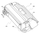
図1は離間部材を装着した際の、タグ取り付け部近傍の斜視図、図2は離間部材装着時における装置本体へのプロセスカートリッジ装着時の略断面図である。 FIG. 1 is a perspective view of the vicinity of the tag mounting portion when the spacing member is mounted, and FIG. 2 is a schematic cross-sectional view when the process cartridge is mounted on the apparatus main body when the spacing member is mounted.
はじめに、取り付け部68近傍の構成及び離間部材9の構成について説明する。カートリッジ枠体としてのドラム枠体162には離間部材9(後述)を取り付けるための取り付け部68、69a、69bが設けられている(図11参照)。これら取り付け部68、69a、69bはカートリッジ装着方向Xと交差する方向、より詳細には、装着方向Xと略直行する方向となるように設けられている。
First, the configuration in the vicinity of the
離間部材9は、前記ドラム枠体162に取り外し可能に係合する係合部と、装置本体Eの運搬時におけるコネクタホルダ8とカートリッジPとの距離を、装置本体Eの使用時におけるコネクタホルダ8とカートリッジPとの距離より広げる離間部93と、を有する。
The separation member 9 is a distance between the engagement portion detachably engaged with the
本実施例では、係合部として、ドラム枠体162に取り外し可能となるように係合する係合部91と、離間部93を挟んで係合部91と反対側に位置し、ドラム枠体162取り外し可能となるように係合する係合部92a、92bと、を有する。
In the present embodiment, as the engaging portion, the engaging
離間部93は、図11に示すメモリタグ6の当接部63を覆って取り付けられている。また、離間部93は、コネクタホルダ8に設けられた、装置本体E使用時に接点部62と電気接点72とが所定圧で接触するためにカートリッジPに対するコネクタホルダ8の位置を規制する当接部71が当接する。その結果、接点部62と電気接点72が非接触となり、カートリッジPを装置本体Eに装着した状態で運搬しても、電気接点72や接点部62の損傷(例えば変形・摩耗)を防ぐことができる。
The
また、離間部材9は、係合部91、92a、92b、離間部93により囲まれた開口部95と、把手部94とを有する。開口部には接点部62が位置し、コネクタ7の電気接点72と離間部材9との干渉を回避しつつ、接点部62と電気接点72とを離間することができる。そのため、離間部材9を薄くすることができ、また、形状を簡単にすることができる。よって、コストを削減することができる。
The separation member 9 includes an
また、離間部材9は、係合部91を回転中心として、係合部91に対して係合部92a、92bより離れた位置に設けられた把手部94をカートリッジPの装着方向Xあるいは取り出し方向Yに対して略直行する着脱方向Zに動作させることにより、ドラム枠体162から容易に取り外すことができる。
Further, the separation member 9 has the
次に離間部材9が取り付けられた状態でのカートリッジPを装置本体Eに装着する動作にしたがって、コネクタ7とメモリタグ6と離間部材9との関係を説明する。
Next, the relationship among the
カートリッジPを挿入していくと、長手方向(図12中A方向)に移動可能に配置されたコネクタホルダ8の位置決め部83が、ドラム枠体162に設けられたコネクタホルダ8の位置決め部67に入る。これにより、コネクタ7の長手方向位置決めが行われる。
When the cartridge P is inserted, the positioning
次にカートリッジPに設けられた突き当て部65a、66aに、装置本体Eに設けられたガイドリブ部84、85が当接する。この当接状態において、コネクタ7の電気接点72及び当接部71は、メモリタグ6及びメモリタグ6を保持しているドラム枠体162及び離間部材9に接触しない。この当接した状態でカートリッジPがさらに挿入され、装置本体Eの所定位置に装着される直前にコネクタホルダ8のガイドリブ部84、85が突き当て部65a、66aから外れる。そして、ガイドリブ部84、85は、突き当て部65a、66aのプロセスカートリッジ挿入方向奥側に設けられた逃げ部65b、66bに位
置する。
Next, the
この際に当接部71が離間部93に当接することで電気接点72と接点部62が離間される。そして、電気接点72は接点部62にも接触しないフリーな状態となる。
At this time, the
コネクタ7の当接部71が離間部材9の離間部93に当接する際に、離間部材9にはカートリッジ装着方向とは逆の方向に力F1が作用する。しかし、上述のように離間部材9とドラム枠体162の取り付けがカートリッジ着脱方向とは交差する方向には外れないように係合している。そのために離間部材9はカートリッジPに押し付けられる方向に力が作用し外れることはない。
When the
換言すれば、カートリッジPの装着方向X先端側に位置する係合部92(92a、92b)は、カートリッジPを装置本体Eに装着する際に、ドラム枠体162に押し付けられる。そのため、離間部材9がドラム枠体162から外れることがない。
In other words, the engaging portion 92 (92a, 92b) positioned on the front end side in the mounting direction X of the cartridge P is pressed against the
このようにカートリッジPを装置本体Eに装着した状態において、離間部材9によって電気接点72はフリーとなっている。そのために運搬時において電気接点72や接点部62が損傷(例えば変形・摩耗)することはない。
Thus, in the state where the cartridge P is mounted on the apparatus main body E, the
上記状態でユーザ先まで運搬された後、ユーザは開梱を行う。まず、電子写真画像形成装置を梱包箱から取り出す。その後、カートリッジPを装置本体Eから取り外す。この際の離間部材9を取り外す動きについて説明する。 After being transported to the user in the above state, the user unpacks. First, the electrophotographic image forming apparatus is taken out from the packaging box. Thereafter, the cartridge P is removed from the apparatus main body E. The movement of removing the separating member 9 at this time will be described.
ユーザは梱包箱から装置本体Eを取り出す。そして、カートリッジアクセスドアDを開けて、装置本体EからカートリッジPを取り出す。この取り出す際に離間部材9にはカートリッジ取り出し方向とは逆の方向に力F2が作用する。しかし、上述のように離間部材9とドラム枠体162の取り付けがカートリッジ着脱方向とは交差する方向に外れないように引っかかり形状が構成されているために離間部材9はカートリッジPに押し付けられる方向に力が作用し外れることはない。
The user takes out the apparatus main body E from the packaging box. Then, the cartridge access door D is opened, and the cartridge P is taken out from the apparatus main body E. At the time of taking out, a force F2 acts on the separating member 9 in a direction opposite to the cartridge taking out direction. However, since the hooking shape is configured so that the attachment of the separation member 9 and the
換言すれば、カートリッジPの取り出し方向Y先端側に位置する係合部91は、カートリッジPを装置本体Eから取り出す際に、ドラム枠体162に押し付けられる。そのため、離間部材9がドラム枠体162から外れることがない。なお、係合部92にかかる力F1、係合部91にかかる力F2の向きは互いに逆方向であればよく、本実施例とは逆の組み合わせであってもよい。
In other words, the engaging
その後、ドラム枠体162に設けられた逃げ部65b、66bに位置していたガイドリブ部84、85は突き当て部65a、66aに当接する。この当接状態においてはコネクタ7の電気接点72及び当接部71は、メモリタグ6及びメモリタグ6を保持しているカートリッジ枠体及び離間部材9に接触しない。このままカートリッジPを取り外すとガイドリブ部84、85は突き当て部65a、66aから離間し電気接点72や接点部62は変形・摩耗することなくプロセスカートリッジが取り出される。次にユーザが離間部材9に設けられた把手部94をつかむ。そして把持部94を離間部材着脱方向Z(カートリッジ着脱方向とは略直行方向)に回動させることで、容易に離間部材9をドラム枠体162から取り外すことができる。
Thereafter, the
本発明に係る実施例2について図面に基づいて説明する。ただし、実施例1で説明したものと同じ構成には同一の符号を示す。また、実施例1と同様の構成及び機能についての説明は省略し、本実施例の特徴部分についてのみ説明する。実施例2では、離間部材29
を装置本体E側に備えている点が実施例1と大きく異なる点である。
A second embodiment according to the present invention will be described with reference to the drawings. However, the same components as those described in the first embodiment are denoted by the same reference numerals. Also, the description of the same configuration and function as in the first embodiment is omitted, and only the characteristic part of the present embodiment will be described. In the second embodiment, the
Is significantly different from the first embodiment.
(離間部材の構成及びプロセスカートリッジ装着時の動作)
カートリッジPを装着した状態において、装置本体E側の電気接点72とメモリタグ6の接点部62とを離間し接触させないようにするための離間部材29の構成及び離間部材29を備えた装置本体Eにプロセスカートリッジを装着する際の動作について図14、図15、図16を用いて説明する。
(Configuration of separation member and operation when process cartridge is mounted)
In the state where the cartridge P is mounted, the configuration of the
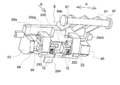
図14、図15は離間部材装着時における装置本体のコネクタ取り付け部近傍の斜視図、図16は離間部材を備えた装置本体Eにプロセスカートリッジ装着した状態の略断面図である。 14 and 15 are perspective views of the vicinity of the connector mounting portion of the apparatus main body when the separation member is mounted, and FIG.
はじめに、本実施例におけるコネクタ7取り付け部近傍の構成及び離間部材29の構成についてから説明する。
First, the configuration in the vicinity of the
コネクタホルダ8には離間部材29(後述)を取り付けるための取り付け部88、89a、89bが設けられている。これら取り付け部はカートリッジ着脱方向と略直行する方向となるように設けられている。
The
離間部材29はコネクタホルダ8に取り外し可能に係合する係合部と、装置本体Eの運搬時におけるコネクタホルダ8とカートリッジPとの距離を、装置本体Eの使用時におけるコネクタホルダ8とカートリッジPとの距離より広げる離間部293と、を有する。
The
本実施例では、係合部として、コネクタホルダ8に取り外し可能となるように係合する係合部292a、292bと、離間部293を挟んで係合部292a、292bと反対側に位置し、コネクタホルダ8に取り外し可能に係合する係合部291と、から構成されている。
In this embodiment, the engaging portions are located on the opposite side of the engaging
また、離間部293は、コネクタホルダ8に設けられた、装置本体E使用時に接点部62と電気接点72とが所定圧で接触するためにカートリッジPに対するコネクタホルダ8の位置を規制する当接部71を覆う。さらには、メモリタグ6の当接部63が当接する。その結果、接点部62と電気接点72が非接触となり、カートリッジPを装置本体Eに装着した状態で輸送・運搬しても、電気接点72や接点部62の損傷を防ぐことができる。
Further, the
また、離間部材29は、係合部291、292a、292b、離間部293により囲まれた開口部295と、把手部294とを有する。開口部には接点部62が位置し、コネクタ7の電気接点72と離間部材29との干渉を回避しつつ、接点部62と電気接点72とを離間することができる。そのため、離間部材29を薄くすることができ、形状を簡単にでき、コストを削減しつつ簡便に製造することができる。
In addition, the
また、離間部材29は、係合部292a、292bを回転中心として、係合部292a、292bに対して係合部291より離れた位置に設けられた把手部294をカートリッジPの装着方向Xあるいは取り出し方向Yに対して略直行する着脱方向Zに動作させることにより容易に取り外すことができる。
Further, the
次に離間部材29を備えた装置本体EにカートリッジPを装着する動作の際のコネクタ7とメモリタグ6と離間部材29との関係を説明する。
Next, the relationship among the
カートリッジPを挿入していくと、長手方向(図14中A方向)に移動可能に配置されたコネクタホルダ8の位置決め部83が、ドラム枠体162に設けられた本体側コネクタ
ホルダ8の長手方向位置決め部67に入り込む。そして、コネクタ7の長手方向位置決めが行われる。
When the cartridge P is inserted, the positioning
次にカートリッジPに設けられた突き当て部65a、66aに、装置本体Eに設けられたガイドリブ部84、85が当接する。この当接状態においてはコネクタ7の電気接点72及び当接部71は、メモリタグ6及びメモリタグ6を保持しているドラム枠体162及び離間部材29に接触しない。この当接した状態でガイドリブ部84、85が突き当て部65a、66aから外れる。そして、ガイドリブ部84、85は、突き当て部65a、66aのプロセスカートリッジ挿入方向奥側に設けられた逃げ部65b、66bに位置し、ガイドリブ部84、85はドラム枠体162から離間する。
Next, the
この際にコネクタ7の当接部71が離間部材29の離間部293で覆われる。そして、離間部293が当接部71とメモリタグ6の当接部63とにより挟まれることで電気接点72と接点部62が離間され、電気接点72はメモリタグ6の接点部62にも接触しないフリーな状態となる。
At this time, the
コネクタ7の当接部71が離間部材29の離間部293に当接する際に、離間部材29にはカートリッジ装着方向と同一の方向に力F1’が作用する。しかし、上述のように離間部材29とコネクタホルダ8の取り付け関係がカートリッジ着脱方向とは略直行する方向にはずれないように引っかかり形状が構成されているために離間部材29はコネクタホルダ8に押し付けられる方向に力が作用し外れることはない。
When the
換言すれば、カートリッジPの装着方向X後端側に位置する係合部292(292a、292b)は、カートリッジPを装置本体Eへ装着する際に、コネクタホルダ8に押し付けられるため、離間部材29がコネクタホルダ8から外れることがない。
In other words, the engaging portion 292 (292a, 292b) positioned on the rear end side in the mounting direction X of the cartridge P is pressed against the
このようにカートリッジPを装置本体Eに装着した状態において、離間部材29によって電気接点72はフリーとなっているために輸送・運搬時において電気接点72や接点部62が変形・摩耗することはない。
Thus, in the state where the cartridge P is mounted on the apparatus main body E, the
上記状態でユーザ先まで運搬された後、ユーザは開梱を行いカートリッジPを装置本体Eから取り外す。この際の離間部材29を取り外す動きについて説明する。
After being transported to the user in the above state, the user unpacks and removes the cartridge P from the apparatus body E. The movement of removing the
ユーザは梱包箱から装置本体Eを取り出し、カートリッジアクセスドアDを開けカートリッジPを取り出す。この取り出す際に離間部材29にはカートリッジ取り出し方向と同一の方向に力F2’が作用する。しかし、上述のように離間部材29とコネクタホルダ8の取り付け関係がカートリッジ着脱方向とは略直行する方向に外れないように引っかかり形状が構成されているために離間部材29はコネクタホルダ8に押し付けられる方向に力が作用し外れることはない。
The user takes out the apparatus main body E from the packing box, opens the cartridge access door D, and takes out the cartridge P. At the time of taking out, a force F2 'acts on the separating
換言すれば、カートリッジPの取り出し方向Y後端側に位置する係合部291は、カートリッジPを装置本体Eから取り出す際に、コネクタホルダ8に押し付けられるため、離間部材29がコネクタホルダ8から外れることがない。なお、係合部292にかかる力F1’、係合部291にかかる力F2’の向きは互いに逆方向であればよく、本実施例とは逆の組み合わせであってもよい。
In other words, the engaging
その後、ドラム枠体162に設けられた逃げ部65b、66bに位置していたガイドリブ部84、85は突き当て部65a、66aに当接する。この当接状態においてはコネクタ7の電気接点72及び当接部71はメモリタグ6及びメモリタグ6を保持しているドラム枠体162及び離間部材29に接触しない。このままカートリッジPを取り外すとガイ
ドリブ部84、85は突き当て部65a、66aから離間し電気接点72や接点部62は変形・摩耗することなくプロセスカートリッジが取り出される。次にユーザは離間部材29に設けられた把手部294を離間部材着脱方向Z(カートリッジ着脱方向とは略直行方向)に回動させることで容易に離間部材29を取り外すことができる。
Thereafter, the
実施例1、実施例2は共に、カートリッジPに設けられたメモリタグ6の接点部62と装置本体Eに設けられた電気接点72とを離間する構成について説明したが、本発明はこれら接触部への適用に限定されるものではない。
In both the first and second embodiments, the configuration in which the
例えば、カートリッジPの帯電接点153と装置本体Eの帯電接点125との離間にも好適に用いることができる。また、カートリッジPの現像接点165と装置本体Eの現像接点126との離間にも好適に用いることができる。
For example, it can be suitably used to separate the
(他の実施例)
前述した実施例では装置本体側に可動部材を設ける構成を例示したが、プロセスカートリッジ側に可動部材を設ける構成においても上述構成を適用しうる。
(Other examples)
In the above-described embodiments, the configuration in which the movable member is provided on the apparatus main body side is illustrated, but the above-described configuration can be applied to the configuration in which the movable member is provided on the process cartridge side.
また、前述した実施例では、電子写真画像形成装置としてレーザビームプリンタを例示したが、本発明は、上記レーザビームプリンタに限定されるものではない。 In the above-described embodiments, the laser beam printer is exemplified as the electrophotographic image forming apparatus. However, the present invention is not limited to the laser beam printer.
本発明が適用できる他の電子写真画像形成装置としては、電子写真画像形成プロセスを用いて、記録紙、OHPシート、布等の記録媒体に画像を形成するものであればよい。例えば、電子写真複写機、電子写真プリンタ(例えば、LEDプリンタ、レーザビームプリンタ等)、電子写真ファクシミリ装置、及び電子写真ワードプロセッサ等の他の電子写真画像形成装置においても本発明を好適に適用しうる。 Other electrophotographic image forming apparatuses to which the present invention can be applied may be any apparatus that forms an image on a recording medium such as recording paper, an OHP sheet, or a cloth using an electrophotographic image forming process. For example, the present invention can be suitably applied to other electrophotographic image forming apparatuses such as electrophotographic copying machines, electrophotographic printers (for example, LED printers, laser beam printers, etc.), electrophotographic facsimile apparatuses, and electrophotographic word processors. .
また、前述した実施例では、帯電手段、現像手段又はクリーニング手段と電子写真感光体とを一体的にカートリッジ化し、このカートリッジを電子写真画像形成装置本体に対して着脱可能とするプロセスカートリッジを例示したが、本発明は、上記プロセスカートリッジに限定されるものではない。 Further, in the above-described embodiments, the process cartridge in which the charging unit, the developing unit or the cleaning unit and the electrophotographic photosensitive member are integrally formed into a cartridge and the cartridge is detachable from the main body of the electrophotographic image forming apparatus is illustrated. However, the present invention is not limited to the process cartridge.
本発明が適用できる他のプロセスカートリッジとしては、帯電手段、現像手段、クリーニング手段の少なくとも1つと電子写真感光体とを一体的にカートリッジ化して電子写真画像形成装置本体に着脱可能とするものでもよい。あるいは、少なくとも現像手段と電子写真感光体とを一体的にカートリッジ化して電子写真画像形成装置本体に着脱可能とするものでもよい。 As another process cartridge to which the present invention can be applied, at least one of a charging unit, a developing unit, and a cleaning unit and an electrophotographic photosensitive member may be integrated into a cartridge so as to be removable from the main body of the electrophotographic image forming apparatus. . Alternatively, at least the developing unit and the electrophotographic photosensitive member may be integrated into a cartridge so that the cartridge can be attached to and detached from the main body of the electrophotographic image forming apparatus.
6 メモリタグ
7 コネクタ
8 コネクタホルダ
9、29 離間部材
61 記憶素子部
62 接点部
63 当接部
64 プリント基板
71 当接部
72 電気接点
91 係合部
92 係合部
93 離間部
94 把手部
95 開口部
100 感光体ユニット
125 帯電接点
126 現像接点
153 帯電接点
162 ドラム枠体(カートリッジ枠体)
164 現像枠体(カートリッジ枠体)
165 現像接点
200 現像ユニット
291 係合部
292 係合部
293 離間部
294 把手部
295 開口部
E 電子写真画像形成装置本体
P プロセスカートリッジ
X 装着方向
Y 取り出し方向
Z 離間部材着脱方向
6
164 Development frame (cartridge frame)
165
Claims (13)
(i)前記電子写真画像形成装置の装置本体に移動可能に設けられた可動部材と、
(ii)前記可動部材に設けられた本体電気接点と、
(iii)前記ユニットを取り外し可能に装着する装着部と、
(iv)前記装着部に装着された前記ユニットであって、前記ユニットが前記装置本体に装着されて、前記記録媒体に画像を形成する画像形成時において、前記本体電気接点と接触可能なユニット電気接点を有する前記ユニットと、
(v)前記ユニットを装着した状態で前記電子写真画像形成装置を運搬する際に、前記可動部材及び前記ユニットと当接することで、前記本体電気接点と前記ユニット電気接点との間に隙間を設けて、前記本体電気接点と前記ユニット電気接点とを離間させる離間部材と、
を有することを特徴とする電子写真画像形成装置。 An electrophotographic image forming apparatus for forming an image on a recording medium, wherein the electrophotographic image forming apparatus can be transported in a state where the unit is mounted.
(I) a movable member movably provided in the main body of the electrophotographic image forming apparatus;
(Ii) a main body electrical contact provided on the movable member;
(Iii) a mounting portion for detachably mounting the unit;
(Iv) The unit mounted on the mounting unit, wherein the unit is mounted on the apparatus main body and can be brought into contact with the main body electrical contact when forming an image on the recording medium. The unit having contacts;
(V) When transporting the electrophotographic image forming apparatus with the unit mounted, a gap is formed between the main body electrical contact and the unit electrical contact by contacting the movable member and the unit. A separating member for separating the main body electrical contact and the unit electrical contact;
An electrophotographic image forming apparatus comprising:
前記ユニットを装着した状態で前記電子写真画像形成装置を運搬する際に、前記支持部材と前記離間部材とが当接することで、前記本体電気接点と前記ユニット電気接点とを離間させることを特徴とする請求項1又は2に記載の電子写真画像形成装置。 The movable member has a support member that supports the body electrical contact,
When the electrophotographic image forming apparatus is transported in a state where the unit is mounted, the main body electrical contact and the unit electrical contact are separated by contacting the support member and the separation member. The electrophotographic image forming apparatus according to claim 1 or 2.
前記ユニットを装着した状態で前記電子写真画像形成装置を運搬する際には、前記離間部材は前記当接部と当接することで、前記本体電気接点と前記ユニット電気接点とを離間させることを特徴とする請求項1又は2に記載の電子写真画像形成装置。 The movable member has a contact portion that contacts the unit so that the unit electrical contact and the main body electrical contact come into contact with each other at a predetermined pressure during the image formation,
When transporting the electrophotographic image forming apparatus while wearing the unit, the spacing member by contact with the abutment portion, that separating the said unit electrically contacts with said main body electrical contact The electrophotographic image forming apparatus according to claim 1, wherein the apparatus is an electrophotographic image forming apparatus.
前記ユニットを装着した状態で前記電子写真画像形成装置を運搬する際に、前記基板と前記離間部材とが当接することで、前記本体電気接点と前記ユニット電気接点とを離間させることを特徴とする請求項1又は3に記載の電子写真画像形成装置。 The unit has a substrate on which the unit electrical contacts are provided;
When carrying the electrophotographic image forming apparatus with the unit mounted, the main body electrical contact and the unit electrical contact are separated from each other by contacting the substrate and the separation member. The electrophotographic image forming apparatus according to claim 1 or 3.
前記ユニットを装着した状態で前記電子写真画像形成装置を運搬する際に、前記装置本体に移動可能に設けられた可動部材であって前記本体電気接点を有する可動部材及び前記ユニットと当接することで、前記本体電気接点と前記ユニット電気接点との間に隙間を設けて、前記本体電気接点と前記ユニット電気接点とを離間させることを特徴とする離間部材。 An electrophotographic image forming apparatus for forming an image on a recording medium, wherein a unit having a unit electrical contact is attached to the apparatus main body of the electrophotographic image forming apparatus, and at the time of image formation for forming an image on the recording medium, A separation member used when an electrophotographic image forming apparatus having a main body electrical contact capable of contacting with the unit electrical contact is transportable in a state where the unit is mounted on the apparatus main body,
When transporting the electrophotographic image forming apparatus while wearing the unit, a movable member which is movable to contact with the movable member and the unit having a main body electrical contact to said device body The spacing member is characterized in that a gap is provided between the body electrical contact and the unit electrical contact to separate the body electrical contact from the unit electrical contact.
Priority Applications (4)
| Application Number | Priority Date | Filing Date | Title |
|---|---|---|---|
| JP2004066364A JP4250555B2 (en) | 2004-03-09 | 2004-03-09 | Electrophotographic image forming apparatus and spacing member |
| US11/072,506 US7203442B2 (en) | 2004-03-09 | 2005-03-07 | Image forming apparatus, unit mountable thereto and separating member |
| CNB200510053658XA CN100392533C (en) | 2004-03-09 | 2005-03-09 | Image forming apparatus, unit mountable thereto and separating member |
| KR1020050019508A KR100690486B1 (en) | 2004-03-09 | 2005-03-09 | Image forming apparatus, unit mountable thereto and separating member |
Applications Claiming Priority (1)
| Application Number | Priority Date | Filing Date | Title |
|---|---|---|---|
| JP2004066364A JP4250555B2 (en) | 2004-03-09 | 2004-03-09 | Electrophotographic image forming apparatus and spacing member |
Publications (3)
| Publication Number | Publication Date |
|---|---|
| JP2005257814A JP2005257814A (en) | 2005-09-22 |
| JP2005257814A5 JP2005257814A5 (en) | 2008-12-04 |
| JP4250555B2 true JP4250555B2 (en) | 2009-04-08 |
Family
ID=34918323
Family Applications (1)
| Application Number | Title | Priority Date | Filing Date |
|---|---|---|---|
| JP2004066364A Expired - Lifetime JP4250555B2 (en) | 2004-03-09 | 2004-03-09 | Electrophotographic image forming apparatus and spacing member |
Country Status (4)
| Country | Link |
|---|---|
| US (1) | US7203442B2 (en) |
| JP (1) | JP4250555B2 (en) |
| KR (1) | KR100690486B1 (en) |
| CN (1) | CN100392533C (en) |
Families Citing this family (36)
| Publication number | Priority date | Publication date | Assignee | Title |
|---|---|---|---|---|
| JP4455124B2 (en) * | 2004-03-31 | 2010-04-21 | キヤノン株式会社 | Electrophotographic image forming apparatus |
| KR100727943B1 (en) * | 2005-06-27 | 2007-06-14 | 삼성전자주식회사 | Toner cartridge having the life detection board built-in and electrophotographic image forming apparatus using the same |
| JP4732125B2 (en) * | 2005-10-28 | 2011-07-27 | キヤノン株式会社 | Image forming apparatus |
| JP4847200B2 (en) * | 2006-04-27 | 2011-12-28 | キヤノン株式会社 | Image forming apparatus |
| JP5393001B2 (en) * | 2006-06-26 | 2014-01-22 | キヤノン株式会社 | Process cartridge, process cartridge assembly method, and disassembly method |
| JP4370532B2 (en) * | 2007-03-28 | 2009-11-25 | ブラザー工業株式会社 | Image forming apparatus |
| JP4994977B2 (en) * | 2007-07-06 | 2012-08-08 | 京セラドキュメントソリューションズ株式会社 | Image forming apparatus |
| KR100889820B1 (en) * | 2007-09-19 | 2009-03-20 | 삼성전자주식회사 | Developing device and image forming apparatus having the same |
| JP4440295B2 (en) * | 2007-10-31 | 2010-03-24 | キヤノン株式会社 | Process cartridge remanufacturing method |
| JP5344566B2 (en) * | 2008-02-05 | 2013-11-20 | キヤノン株式会社 | Image forming apparatus and cartridge |
| JP5288900B2 (en) | 2008-06-20 | 2013-09-11 | キヤノン株式会社 | Process cartridge and electrophotographic image forming apparatus |
| JP4440318B2 (en) * | 2008-07-31 | 2010-03-24 | キヤノン株式会社 | Process cartridge and electrophotographic image forming apparatus |
| JP5653124B2 (en) * | 2010-08-17 | 2015-01-14 | キヤノン株式会社 | Color electrophotographic image forming apparatus |
| US8867970B2 (en) | 2011-12-30 | 2014-10-21 | Lexmark International, Inc. | Toner cartridges having positional control features |
| US8867966B2 (en) * | 2011-12-30 | 2014-10-21 | Lexmark International, Inc. | Toner cartridge for use in an image forming device |
| US8879953B2 (en) * | 2012-06-25 | 2014-11-04 | Lexmark International, Inc. | Retainer assembly having positioning features for processing circuitry used within an image forming device supply item |
| JP6140963B2 (en) * | 2012-09-27 | 2017-06-07 | キヤノン株式会社 | Cartridge and image forming apparatus |
| JP5975823B2 (en) | 2012-09-28 | 2016-08-23 | キヤノン株式会社 | Cartridge and image forming apparatus |
| PL3214503T3 (en) * | 2013-01-24 | 2020-07-13 | Hewlett-Packard Development Company, L.P. | Electrophotographic image forming apparatus and development cartridge |
| FR3015927A1 (en) * | 2013-12-27 | 2015-07-03 | Oreal | TRANSFER MAKEUP METHOD AND ASSOCIATED DEVICE. |
| JP6373065B2 (en) | 2014-05-29 | 2018-08-15 | キヤノン株式会社 | Image forming apparatus |
| JP6524723B2 (en) * | 2015-03-09 | 2019-06-05 | 富士ゼロックス株式会社 | Image forming device |
| JP6582972B2 (en) | 2015-12-25 | 2019-10-02 | ブラザー工業株式会社 | Developer cartridge |
| EP3506023A4 (en) | 2016-08-26 | 2020-05-13 | C/o Canon Kabushiki Kaisha | Drum unit, cartridge, electrophotographic image forming device, and coupling member |
| JP7062875B2 (en) * | 2017-03-07 | 2022-05-09 | ブラザー工業株式会社 | Drum cartridges and process cartridges |
| JP7091096B2 (en) | 2017-03-15 | 2022-06-27 | キヤノン株式会社 | Drum unit, cartridge, process cartridge and electrophotographic image forming apparatus |
| JP6822279B2 (en) * | 2017-03-31 | 2021-01-27 | ブラザー工業株式会社 | Develop cartridges, process cartridges, and image forming equipment |
| US9989917B1 (en) * | 2017-05-17 | 2018-06-05 | Lexmark International, Inc. | Toner cartridge with positional control features |
| CN116184782A (en) * | 2017-12-13 | 2023-05-30 | 佳能株式会社 | Cartridge and image forming apparatus |
| JP7058992B2 (en) | 2017-12-13 | 2022-04-25 | キヤノン株式会社 | Image forming equipment and cartridge |
| US10627780B2 (en) | 2018-01-23 | 2020-04-21 | Canon Kabushiki Kaisha | Cartridge and image forming apparatus |
| JP7262983B2 (en) | 2018-11-30 | 2023-04-24 | キヤノン株式会社 | Process cartridge and image forming apparatus |
| EP3699693B1 (en) | 2019-02-19 | 2022-09-21 | Canon Kabushiki Kaisha | Positioning apparatus and image forming apparatus |
| JP7305417B2 (en) | 2019-04-25 | 2023-07-10 | キヤノン株式会社 | Process cartridge and image forming apparatus |
| JP2023057884A (en) | 2021-10-12 | 2023-04-24 | キヤノン株式会社 | process cartridge |
| US20230418221A1 (en) * | 2022-06-24 | 2023-12-28 | Canon Kabushiki Kaisha | Cartridge, toner cartridge, and image forming apparatus |
Family Cites Families (19)
| Publication number | Priority date | Publication date | Assignee | Title |
|---|---|---|---|---|
| JP3332818B2 (en) * | 1996-08-29 | 2002-10-07 | キヤノン株式会社 | Process cartridge, electrophotographic image forming apparatus, and connection terminal connection method |
| JP2001034055A (en) | 1999-02-18 | 2001-02-09 | Canon Inc | Developer container and cartridge |
| EP1083464A3 (en) | 1999-09-09 | 2003-02-12 | Canon Kabushiki Kaisha | Developing apparatus, process cartridge, feeding member and an elastic sheet |
| JP2001092335A (en) | 1999-09-17 | 2001-04-06 | Canon Inc | Process cartridge, electrophotographic image forming device and developer quantity detection member |
| JP4365969B2 (en) | 2000-01-20 | 2009-11-18 | キヤノン株式会社 | Developing device, process cartridge, and electrophotographic image forming apparatus |
| JP4463934B2 (en) | 2000-04-05 | 2010-05-19 | キヤノン株式会社 | Image forming apparatus |
| JP2001290360A (en) | 2000-04-07 | 2001-10-19 | Canon Inc | Developer container, processing cartridge, developing device and image forming device |
| JP2001290359A (en) | 2000-04-07 | 2001-10-19 | Canon Inc | Developer container, developer amount detecting system, process cartridge, developing device and image forming device |
| JP3505485B2 (en) * | 2000-08-04 | 2004-03-08 | シャープ株式会社 | Developing cartridge for image forming apparatus |
| JP4551544B2 (en) * | 2000-08-25 | 2010-09-29 | キヤノン株式会社 | Electrophotographic image forming apparatus |
| JP3492301B2 (en) * | 2000-08-25 | 2004-02-03 | キヤノン株式会社 | Unit, process cartridge, and electrophotographic image forming apparatus |
| JP3442047B2 (en) | 2000-11-17 | 2003-09-02 | キヤノン株式会社 | Process cartridge and electrophotographic image forming apparatus |
| JP4928023B2 (en) * | 2001-04-27 | 2012-05-09 | キヤノン株式会社 | Image forming apparatus |
| JP3840063B2 (en) * | 2001-04-27 | 2006-11-01 | キヤノン株式会社 | Process cartridge |
| JP3809375B2 (en) * | 2001-12-28 | 2006-08-16 | キヤノン株式会社 | Image forming apparatus |
| JP2003307931A (en) | 2002-04-17 | 2003-10-31 | Canon Inc | Process cartridge and electrophotographic image forming apparatus |
| JP4097456B2 (en) | 2002-05-09 | 2008-06-11 | シャープ株式会社 | Packing tool for image forming apparatus and packing method for image forming apparatus |
| JP4194298B2 (en) * | 2002-05-17 | 2008-12-10 | キヤノン株式会社 | Information storage medium, unit, process cartridge, developing cartridge, and electrophotographic image forming apparatus |
| JP3625470B1 (en) | 2003-09-30 | 2005-03-02 | キヤノン株式会社 | Process cartridge and electrophotographic image forming apparatus |
-
2004
- 2004-03-09 JP JP2004066364A patent/JP4250555B2/en not_active Expired - Lifetime
-
2005
- 2005-03-07 US US11/072,506 patent/US7203442B2/en active Active
- 2005-03-09 CN CNB200510053658XA patent/CN100392533C/en not_active Expired - Fee Related
- 2005-03-09 KR KR1020050019508A patent/KR100690486B1/en not_active IP Right Cessation
Also Published As
| Publication number | Publication date |
|---|---|
| US7203442B2 (en) | 2007-04-10 |
| KR20060043572A (en) | 2006-05-15 |
| JP2005257814A (en) | 2005-09-22 |
| US20050201773A1 (en) | 2005-09-15 |
| KR100690486B1 (en) | 2007-03-09 |
| CN100392533C (en) | 2008-06-04 |
| CN1667526A (en) | 2005-09-14 |
Similar Documents
| Publication | Publication Date | Title |
|---|---|---|
| JP4250555B2 (en) | Electrophotographic image forming apparatus and spacing member | |
| KR100749206B1 (en) | Process cartridge and image forming apparatus usable therewith | |
| US8437661B2 (en) | Process cartridge and electrophotographic image forming apparatus | |
| JP3073102B2 (en) | Process cartridge and image forming apparatus | |
| CN108345203B (en) | Developing device, process cartridge, and image forming apparatus | |
| EP1239336A2 (en) | Image forming apparatus | |
| JP7420979B2 (en) | Process cartridge and image forming device | |
| JP2006071671A (en) | Electrophotographic image forming apparatus and regulating member | |
| US8280288B2 (en) | Image forming device having protection member for protecting peeling claw | |
| JP2009210903A (en) | Image forming apparatus | |
| JP4736568B2 (en) | Image forming apparatus, process cartridge, and developing cartridge | |
| JP2006058459A (en) | Separating member, process cartridge and electrophotographic image forming apparatus | |
| JP4652384B2 (en) | Image forming apparatus | |
| JP2003195723A (en) | Image forming apparatus | |
| EP3204827B1 (en) | Unit and image forming apparatus | |
| US20210063954A1 (en) | Image forming apparatus | |
| US10627777B2 (en) | Separation holding member, cartridge unit, and packaging body | |
| JP6992372B2 (en) | Replacement unit and image forming device | |
| JP2009210900A (en) | Image forming apparatus | |
| KR100611988B1 (en) | Developer device and image-forming apparatus adopting the same | |
| JP2006064835A (en) | Image forming apparatus | |
| JP4006273B2 (en) | Process cartridge and image forming apparatus | |
| JP7349875B2 (en) | Process cartridges and image forming devices | |
| JPH06210895A (en) | Image forming apparatus | |
| JP2003323016A (en) | Drum holding structure |
Legal Events
| Date | Code | Title | Description |
|---|---|---|---|
| A521 | Request for written amendment filed |
Free format text: JAPANESE INTERMEDIATE CODE: A523 Effective date: 20060925 |
|
| A621 | Written request for application examination |
Free format text: JAPANESE INTERMEDIATE CODE: A621 Effective date: 20060925 |
|
| A521 | Request for written amendment filed |
Free format text: JAPANESE INTERMEDIATE CODE: A523 Effective date: 20081016 |
|
| A871 | Explanation of circumstances concerning accelerated examination |
Free format text: JAPANESE INTERMEDIATE CODE: A871 Effective date: 20081016 |
|
| A975 | Report on accelerated examination |
Free format text: JAPANESE INTERMEDIATE CODE: A971005 Effective date: 20081022 |
|
| A131 | Notification of reasons for refusal |
Free format text: JAPANESE INTERMEDIATE CODE: A131 Effective date: 20081104 |
|
| A521 | Request for written amendment filed |
Free format text: JAPANESE INTERMEDIATE CODE: A523 Effective date: 20081204 |
|
| TRDD | Decision of grant or rejection written | ||
| A01 | Written decision to grant a patent or to grant a registration (utility model) |
Free format text: JAPANESE INTERMEDIATE CODE: A01 Effective date: 20090106 |
|
| A01 | Written decision to grant a patent or to grant a registration (utility model) |
Free format text: JAPANESE INTERMEDIATE CODE: A01 |
|
| A61 | First payment of annual fees (during grant procedure) |
Free format text: JAPANESE INTERMEDIATE CODE: A61 Effective date: 20090119 |
|
| FPAY | Renewal fee payment (event date is renewal date of database) |
Free format text: PAYMENT UNTIL: 20120123 Year of fee payment: 3 |
|
| R150 | Certificate of patent or registration of utility model |
Ref document number: 4250555 Country of ref document: JP Free format text: JAPANESE INTERMEDIATE CODE: R150 Free format text: JAPANESE INTERMEDIATE CODE: R150 |
|
| FPAY | Renewal fee payment (event date is renewal date of database) |
Free format text: PAYMENT UNTIL: 20130123 Year of fee payment: 4 |
|
| FPAY | Renewal fee payment (event date is renewal date of database) |
Free format text: PAYMENT UNTIL: 20140123 Year of fee payment: 5 |
|
| EXPY | Cancellation because of completion of term |