JP4387933B2 - Process cartridge and electrophotographic image forming apparatus - Google Patents
Process cartridge and electrophotographic image forming apparatus Download PDFInfo
- Publication number
- JP4387933B2 JP4387933B2 JP2004352495A JP2004352495A JP4387933B2 JP 4387933 B2 JP4387933 B2 JP 4387933B2 JP 2004352495 A JP2004352495 A JP 2004352495A JP 2004352495 A JP2004352495 A JP 2004352495A JP 4387933 B2 JP4387933 B2 JP 4387933B2
- Authority
- JP
- Japan
- Prior art keywords
- cartridge
- main body
- movable
- image forming
- contact
- Prior art date
- Legal status (The legal status is an assumption and is not a legal conclusion. Google has not performed a legal analysis and makes no representation as to the accuracy of the status listed.)
- Expired - Fee Related
Links
- 238000000034 method Methods 0.000 title claims description 135
- 230000008569 process Effects 0.000 title claims description 124
- 230000009471 action Effects 0.000 claims description 43
- 238000003780 insertion Methods 0.000 claims description 11
- 230000037431 insertion Effects 0.000 claims description 11
- 230000005540 biological transmission Effects 0.000 claims description 4
- 238000010586 diagram Methods 0.000 description 17
- 238000011161 development Methods 0.000 description 14
- 230000000694 effects Effects 0.000 description 12
- 238000012546 transfer Methods 0.000 description 11
- 230000015572 biosynthetic process Effects 0.000 description 10
- 238000004140 cleaning Methods 0.000 description 7
- 230000008878 coupling Effects 0.000 description 7
- 238000010168 coupling process Methods 0.000 description 7
- 238000005859 coupling reaction Methods 0.000 description 7
- 230000007246 mechanism Effects 0.000 description 7
- 239000004519 grease Substances 0.000 description 6
- 230000006835 compression Effects 0.000 description 5
- 238000007906 compression Methods 0.000 description 5
- 229910052751 metal Inorganic materials 0.000 description 5
- 239000002184 metal Substances 0.000 description 5
- 210000004243 sweat Anatomy 0.000 description 5
- 239000000428 dust Substances 0.000 description 4
- 230000002093 peripheral effect Effects 0.000 description 4
- 238000012545 processing Methods 0.000 description 4
- WABPQHHGFIMREM-UHFFFAOYSA-N lead(0) Chemical compound [Pb] WABPQHHGFIMREM-UHFFFAOYSA-N 0.000 description 3
- 238000012423 maintenance Methods 0.000 description 3
- XLOMVQKBTHCTTD-UHFFFAOYSA-N Zinc monoxide Chemical compound [Zn]=O XLOMVQKBTHCTTD-UHFFFAOYSA-N 0.000 description 2
- 108091008695 photoreceptors Proteins 0.000 description 2
- 238000002360 preparation method Methods 0.000 description 2
- 230000001681 protective effect Effects 0.000 description 2
- 238000003756 stirring Methods 0.000 description 2
- 229910000838 Al alloy Inorganic materials 0.000 description 1
- 125000002066 L-histidyl group Chemical group [H]N1C([H])=NC(C([H])([H])[C@](C(=O)[*])([H])N([H])[H])=C1[H] 0.000 description 1
- BUGBHKTXTAQXES-UHFFFAOYSA-N Selenium Chemical compound [Se] BUGBHKTXTAQXES-UHFFFAOYSA-N 0.000 description 1
- GWEVSGVZZGPLCZ-UHFFFAOYSA-N Titan oxide Chemical compound O=[Ti]=O GWEVSGVZZGPLCZ-UHFFFAOYSA-N 0.000 description 1
- 229910052782 aluminium Inorganic materials 0.000 description 1
- XAGFODPZIPBFFR-UHFFFAOYSA-N aluminium Chemical compound [Al] XAGFODPZIPBFFR-UHFFFAOYSA-N 0.000 description 1
- 229910021417 amorphous silicon Inorganic materials 0.000 description 1
- 238000013459 approach Methods 0.000 description 1
- 238000010276 construction Methods 0.000 description 1
- 230000006378 damage Effects 0.000 description 1
- 230000005611 electricity Effects 0.000 description 1
- 150000002500 ions Chemical class 0.000 description 1
- 230000003287 optical effect Effects 0.000 description 1
- 238000005192 partition Methods 0.000 description 1
- 230000035515 penetration Effects 0.000 description 1
- 239000011347 resin Substances 0.000 description 1
- 229920005989 resin Polymers 0.000 description 1
- 230000004044 response Effects 0.000 description 1
- 239000011669 selenium Substances 0.000 description 1
- 229910052711 selenium Inorganic materials 0.000 description 1
- 230000003068 static effect Effects 0.000 description 1
- OGIDPMRJRNCKJF-UHFFFAOYSA-N titanium oxide Inorganic materials [Ti]=O OGIDPMRJRNCKJF-UHFFFAOYSA-N 0.000 description 1
- 239000011787 zinc oxide Substances 0.000 description 1
Images


Classifications
-
- G—PHYSICS
- G03—PHOTOGRAPHY; CINEMATOGRAPHY; ANALOGOUS TECHNIQUES USING WAVES OTHER THAN OPTICAL WAVES; ELECTROGRAPHY; HOLOGRAPHY
- G03G—ELECTROGRAPHY; ELECTROPHOTOGRAPHY; MAGNETOGRAPHY
- G03G21/00—Arrangements not provided for by groups G03G13/00 - G03G19/00, e.g. cleaning, elimination of residual charge
- G03G21/16—Mechanical means for facilitating the maintenance of the apparatus, e.g. modular arrangements
- G03G21/18—Mechanical means for facilitating the maintenance of the apparatus, e.g. modular arrangements using a processing cartridge, whereby the process cartridge comprises at least two image processing means in a single unit
- G03G21/1839—Means for handling the process cartridge in the apparatus body
- G03G21/1842—Means for handling the process cartridge in the apparatus body for guiding and mounting the process cartridge, positioning, alignment, locks
- G03G21/1853—Means for handling the process cartridge in the apparatus body for guiding and mounting the process cartridge, positioning, alignment, locks the process cartridge being mounted perpendicular to the axis of the photosensitive member
-
- G—PHYSICS
- G03—PHOTOGRAPHY; CINEMATOGRAPHY; ANALOGOUS TECHNIQUES USING WAVES OTHER THAN OPTICAL WAVES; ELECTROGRAPHY; HOLOGRAPHY
- G03G—ELECTROGRAPHY; ELECTROPHOTOGRAPHY; MAGNETOGRAPHY
- G03G15/00—Apparatus for electrographic processes using a charge pattern
-
- G—PHYSICS
- G03—PHOTOGRAPHY; CINEMATOGRAPHY; ANALOGOUS TECHNIQUES USING WAVES OTHER THAN OPTICAL WAVES; ELECTROGRAPHY; HOLOGRAPHY
- G03G—ELECTROGRAPHY; ELECTROPHOTOGRAPHY; MAGNETOGRAPHY
- G03G21/00—Arrangements not provided for by groups G03G13/00 - G03G19/00, e.g. cleaning, elimination of residual charge
- G03G21/16—Mechanical means for facilitating the maintenance of the apparatus, e.g. modular arrangements
- G03G21/18—Mechanical means for facilitating the maintenance of the apparatus, e.g. modular arrangements using a processing cartridge, whereby the process cartridge comprises at least two image processing means in a single unit
- G03G21/1839—Means for handling the process cartridge in the apparatus body
- G03G21/1867—Means for handling the process cartridge in the apparatus body for electrically connecting the process cartridge to the apparatus, electrical connectors, power supply
- G03G21/1871—Means for handling the process cartridge in the apparatus body for electrically connecting the process cartridge to the apparatus, electrical connectors, power supply associated with a positioning function
-
- G—PHYSICS
- G03—PHOTOGRAPHY; CINEMATOGRAPHY; ANALOGOUS TECHNIQUES USING WAVES OTHER THAN OPTICAL WAVES; ELECTROGRAPHY; HOLOGRAPHY
- G03G—ELECTROGRAPHY; ELECTROPHOTOGRAPHY; MAGNETOGRAPHY
- G03G2221/00—Processes not provided for by group G03G2215/00, e.g. cleaning or residual charge elimination
- G03G2221/16—Mechanical means for facilitating the maintenance of the apparatus, e.g. modular arrangements and complete machine concepts
- G03G2221/1651—Mechanical means for facilitating the maintenance of the apparatus, e.g. modular arrangements and complete machine concepts for connecting the different parts
- G03G2221/166—Electrical connectors
-
- G—PHYSICS
- G03—PHOTOGRAPHY; CINEMATOGRAPHY; ANALOGOUS TECHNIQUES USING WAVES OTHER THAN OPTICAL WAVES; ELECTROGRAPHY; HOLOGRAPHY
- G03G—ELECTROGRAPHY; ELECTROPHOTOGRAPHY; MAGNETOGRAPHY
- G03G2221/00—Processes not provided for by group G03G2215/00, e.g. cleaning or residual charge elimination
- G03G2221/16—Mechanical means for facilitating the maintenance of the apparatus, e.g. modular arrangements and complete machine concepts
- G03G2221/18—Cartridge systems
- G03G2221/183—Process cartridge
Description
本発明は、プロセスカートリッジ、及び、前記プロセスカートリッジを用いる電子写真画像形成装置に関する。 The present invention relates to a process cartridge and an electrophotographic image forming apparatus using the process cartridge.
ここで電子写真画像形成装置とは、電子写真画像形成プロセスを用いて記録媒体(例えば、記録用紙、OHPシート等)に画像を形成するものである。例えば、電子写真複写機、電子写真プリンター等が含まれる。 Here, the electrophotographic image forming apparatus forms an image on a recording medium (for example, recording paper, OHP sheet, etc.) using an electrophotographic image forming process. For example, an electrophotographic copying machine, an electrophotographic printer, and the like are included.
また、プロセスカートリッジとは、プロセス手段としての帯電部材、現像部材の少なくとも1つと電子写真感光体とを一体的にカートリッジ化して電子写真画像形成装置本体に着脱可能としたものである。 Further, the process cartridge is a cartridge in which at least one of a charging member and a developing member as process means and an electrophotographic photosensitive member are integrally formed so as to be detachable from the main body of the electrophotographic image forming apparatus.
プロセスカートリッジ方式の電子写真画像形成装置においては、画像形成装置本体に対するプロセスカートリッジの着脱をサービスマンによらずにユーザー自身で行うことができる。そこで、画像形成装置の操作性を格段に向上させることができた。 In a process cartridge type electrophotographic image forming apparatus, the user can attach and detach the process cartridge to and from the image forming apparatus main body without using a service person. Therefore, the operability of the image forming apparatus can be remarkably improved.
こうした電子写真画像形成装置においては、プロセスカートリッジの有する電子写真感光体(以下、「感光体ドラム」と称す。)を帯電するための帯電部材、或いは、前記感光体ドラムに形成された静電潜像を現像するための現像部材などに電圧を印加する必要がある。 In such an electrophotographic image forming apparatus, a charging member for charging an electrophotographic photosensitive member (hereinafter referred to as “photosensitive drum”) included in a process cartridge, or an electrostatic latent image formed on the photosensitive drum. It is necessary to apply a voltage to a developing member for developing the image.
従来、カートリッジが画像形成装置本体に装着された際に、前記カートリッジと前記装置本体との電気接続を行うために、前記カートリッジの枠体に入力電気接点を設ける。一方、前記装置本体には出力電気接点を設ける。そして、カートリッジが装置本体に装着された際に、前記入力電気接点と前記出力電気接点を接続する。これによって、装置本体からカートリッジに電圧を供給することが行われている。 Conventionally, when a cartridge is mounted on an image forming apparatus main body, an input electrical contact is provided on the frame of the cartridge in order to make an electrical connection between the cartridge and the apparatus main body. On the other hand, the apparatus main body is provided with an output electrical contact. Then, when the cartridge is mounted on the apparatus main body, the input electrical contact and the output electrical contact are connected. Thus, a voltage is supplied from the apparatus main body to the cartridge.
具体的には、次の構成が知られている。 Specifically, the following configuration is known.
端子部材(出力電気接点)を覆う保護板を装置本体に移動可能に設ける。これによって、プリンター(画像形成装置)のメンテナンス作業を行う場合に、オペレータ或いは工具が前記端子部材に接触することを防止する。そして、カートリッジの装置本体への挿入により、前記保護板を退避位置へ退避させる。これによって、装置本体の端子部材とカートリッジの端子部材(入力電気接点)とを電気的に接続可能にする(特許文献1参照)。 A protective plate that covers the terminal member (output electrical contact) is movably provided on the apparatus body. This prevents an operator or tool from coming into contact with the terminal member when performing maintenance work on the printer (image forming apparatus). Then, the protective plate is retracted to the retracted position by inserting the cartridge into the apparatus main body. Thereby, the terminal member of the apparatus main body and the terminal member (input electrical contact) of the cartridge can be electrically connected (see Patent Document 1).
また、ユニットを装置本体から取り外した際に、コネクタピン(出力電気接点)を仕切壁の内側に隠蔽する。これによって、サービスマンやユーザーがコネクタピンに接触することを防止する。そして、ユニットの装置本体への挿入により、前記コネクタピンをユニット挿入部内へ侵入させる。これによって、コネクタピンとユニットのコネクタ部(入力電気接点)とを電気的に接続する(特許文献2参照)。 Further, when the unit is removed from the apparatus main body, the connector pin (output electrical contact) is concealed inside the partition wall. This prevents a serviceman or user from contacting the connector pin. And the said connector pin is penetrated in a unit insertion part by the insertion in the apparatus main body of a unit. As a result, the connector pin and the connector portion (input electrical contact) of the unit are electrically connected (see Patent Document 2).
また、ドラムシャッタに規制部を設ける。そして、この規制部によって電気接点(入力電気接点)を覆う。これによって、前記電気接点に異物が付着して、接点不良が発生することを防止する。そして、カートリッジの装置本体の侵入により、カートリッジの電気接点と装置本体の電気接点(出力電気接点)とを電気的に接続する(特許文献3参照)。 In addition, the drum shutter is provided with a restricting portion. Then, the electrical contact (input electrical contact) is covered by this restricting portion. This prevents foreign matter from adhering to the electrical contact and causing contact failure. Then, the cartridge electrical contact is electrically connected to the electrical contact (output electrical contact) of the device body by the penetration of the device body of the cartridge (see Patent Document 3).
また、接点部材(出力電気接点)を退避位置と正規位置との間を移動可能に設ける。これによって、カートリッジの接点部(入力電気接点)と装置本体の接点部材とを正常に接触させる。そして、カートリッジを装置本体へ侵入させる前には、前記接点部材(出力電気接点)を退避位置へ移動させる。また、カートリッジを装置本体に装着した際には、前記接点部材を正規位置へ移動させる。これによって、前記接点部と前記接点部とを電気的に接続する(特許文献4参照)。
本発明は前記従来技術を更に発展させたものである。 The present invention is a further development of the prior art.
本発明の目的は、プロセスカートリッジを電子写真画像形成装置本体に装着した際に、前記プロセスカートリッジの有する入力電気接点と、前記画像形成装置本体に設けられた出力電気接点との電気接続の信頼性を向上させたプロセスカートリッジ、及び、電子写真画像形成装置を提供することにある。 An object of the present invention is to provide reliability of electrical connection between an input electrical contact of the process cartridge and an output electrical contact provided in the image forming apparatus body when the process cartridge is mounted on the electrophotographic image forming apparatus body. It is an object to provide a process cartridge and an electrophotographic image forming apparatus with improved performance.
本発明の他の目的は、電子写真画像形成装置本体に設けられた電気回路が損傷することを防止できるプロセスカートリッジ、及び、電子写真画像形成装置を提供することにある。 Another object of the present invention is to provide a process cartridge and an electrophotographic image forming apparatus that can prevent an electric circuit provided in the main body of the electrophotographic image forming apparatus from being damaged.
本発明の他の目的は、カートリッジ枠体に対して相対的に移動可能に設けられた可動作動部材であって、前記プロセスカートリッジが前記画像形成装置本体に装着された後に、前記画像形成装置本体から前記プロセスカートリッジに駆動力が伝達されることによって変位し、それにより前記画像形成装置本体に設けられている可変位部材と係合して前記可変位部材を移動させ、前記可変位部材の動きに連動して前記出力電気接点を前記退避位置から前記電気接続位置に、前記弾性機能部材の弾性力に抗して、移動させる可動作動部材を有することによって、前記入力電気接点と、前記出力電気接点との電気接続の信頼性を向上させたプロセスカートリッジ、及び、電子写真画像形成装置を提供することにある。 Another object of the present invention is a movable actuating member provided so as to be movable relative to a cartridge frame, and the image forming apparatus main body after the process cartridge is mounted on the image forming apparatus main body. Is displaced by transmitting a driving force to the process cartridge, thereby engaging the variable position member provided in the main body of the image forming apparatus to move the variable position member and moving the variable position member. A movable actuating member that moves the output electrical contact from the retracted position to the electrical connection position against the elastic force of the elastic functional member in conjunction with the input electrical contact; It is an object of the present invention to provide a process cartridge and an electrophotographic image forming apparatus in which reliability of electrical connection with a contact is improved.
本発明の他の目的は、カートリッジ枠体に対して相対的に移動可能に設けられた可動作動部材であって、前記プロセスカートリッジが前記画像形成装置本体に装着された後に、前記画像形成装置本体から前記プロセスカートリッジに駆動力が伝達されることによって変位し、それにより前記画像形成装置本体に設けられている可変位部材と係合して前記可変位部材を移動させ、前記可変位部材の動きに連動して前記出力電気接点を前記退避位置から前記電気接続位置に、前記弾性機能部材の弾性力に抗して、移動させる可動作動部材を有することによって、前記画像形成装置本体に設けられた電気回路が損傷することを防止できるプロセスカートリッジ、及び、電子写真画像形成装置を提供することにある。 Another object of the present invention is a movable actuating member provided so as to be movable relative to a cartridge frame, and the image forming apparatus main body after the process cartridge is mounted on the image forming apparatus main body. Is displaced by transmitting a driving force to the process cartridge, thereby engaging the variable position member provided in the main body of the image forming apparatus to move the variable position member and moving the variable position member. And a movable operating member that moves the output electrical contact from the retracted position to the electrical connection position against the elastic force of the elastic functional member. An object of the present invention is to provide a process cartridge and an electrophotographic image forming apparatus capable of preventing an electric circuit from being damaged.
本発明の他の目的は、静止している入力電気接点に対して出力電気接点を移動させて、両電気接点を電気的に接続することによって、前記入力電気接点と、前記出力電気接点との電気接続の信頼性を向上させたプロセスカートリッジ、及び、電子写真画像形成装置を提供することにある。 Another object of the present invention is to move the output electrical contact with respect to the stationary input electrical contact so as to electrically connect both the electrical contact, and thereby the input electrical contact and the output electrical contact. It is an object of the present invention to provide a process cartridge and an electrophotographic image forming apparatus with improved electrical connection reliability.
上記目的は本発明に係るプロセスカートリッジ及び電子写真画像形成装置にて達成される。要約すれば、本発明は、その一態様によれば、プロセスカートリッジが取り外し可能に装着されるカートリッジ装着部と、内側板と、前記内側板から前記カートリッジ装着部の設けられた側に突出している電気接続位置と前記電気接続位置から退避した、前記内側板から前記カートリッジ装着部の設けられた側に突出していない退避位置との間を移動可能な出力電気接点と、前記出力電気接点を移動させる可変位部材と、前記出力電気接点を電気接続位置から退避位置に移動させるように前記可変位部材を弾性的に付勢する弾性機能部材と、を有する電子写真画像形成装置本体に取り外し可能に装着されるプロセスカートリッジであって、
電子写真感光体ドラムと、
前記電子写真感光体ドラムに作用するプロセス手段と、
カートリッジ枠体に対して相対的に移動可能に設けられた可動作動部材であって、前記プロセスカートリッジが前記電子写真画像形成装置本体に装着された後に、前記電子写真画像形成装置本体から前記プロセスカートリッジに駆動力が伝達されることによって変位し、それにより前記電子写真画像形成装置本体に設けられている前記可変位部材と係合して前記可変位部材を移動させ、前記可変位部材の動きに連動して前記出力電気接点を前記退避位置から前記電気接続位置に、前記弾性機能部材の弾性力に抗して、移動させる可動作動部材と、
前記電気接続位置に位置せしめられた出力電気接点に係合し、前記プロセス手段が機能するための電圧を受ける入力電気接点と、
を有することを特徴とするプロセスカートリッジ、及び、斯かるプロセスカートリッジを備えた電子写真画像形成装置が提供される。
The above object is achieved by a process cartridge and an electrophotographic image forming apparatus according to the present invention. In summary, according to one aspect of the present invention, a cartridge mounting portion on which a process cartridge is detachably mounted, an inner plate, and a side on which the cartridge mounting portion is provided protrudes from the inner plate. An output electrical contact that is movable between an electrical connection position and a retracted position that is retracted from the electrical connection position and does not protrude from the inner plate to the side where the cartridge mounting portion is provided, and the output electrical contact is moved. Removably mounted on the electrophotographic image forming apparatus main body having a variable position member and an elastic functional member that elastically biases the variable position member so as to move the output electrical contact from the electrical connection position to the retracted position. A process cartridge,
An electrophotographic photosensitive drum;
Process means acting on the electrophotographic photosensitive drum;
A movable actuating member provided so as to be movable relative to a cartridge frame, wherein after the process cartridge is mounted on the electrophotographic image forming apparatus main body, the process cartridge is moved from the electrophotographic image forming apparatus main body. Is displaced by the transmission of the driving force, thereby engaging with the variable position member provided in the main body of the electrophotographic image forming apparatus to move the variable position member, and to move the variable position member. A movable actuating member that moves the output electrical contact from the retracted position to the electrical connection position in opposition to the elastic force of the elastic function member;
An input electrical contact that engages an output electrical contact positioned at the electrical connection location and receives a voltage for the process means to function;
There are provided a process cartridge and an electrophotographic image forming apparatus including the process cartridge.
本発明は、プロセスカートリッジを電子写真画像形成装置本体に装着した際に、前記プロセスカートリッジの有する入力電気接点と、前記画像形成装置本体に設けられた出力電気接点との電気接続の信頼性を向上させることができる。また、電子写真画像形成装置本体に設けられた電気回路が損傷することを防止できる。 The present invention improves the reliability of electrical connection between an input electrical contact of the process cartridge and an output electrical contact provided in the image forming apparatus body when the process cartridge is mounted on the electrophotographic image forming apparatus body. Can be made. Further, it is possible to prevent the electric circuit provided in the electrophotographic image forming apparatus main body from being damaged.
以下、本発明に係るプロセスカートリッジ、及び、電子写真画像形成装置を図面に則して更に詳しく説明する。 Hereinafter, a process cartridge and an electrophotographic image forming apparatus according to the present invention will be described in more detail with reference to the drawings.
実施例1
(1)プロセスカートリッジの概略説明
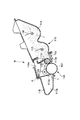
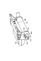
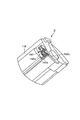
先ず、図1を用いて、本発明の一実施例を適用したプロセスカートリッジ(以下、「カートリッジ」と称す。)Bについて説明する。図1は、カートリッジBの断面図である。
Example 1
(1) General Description of Process Cartridge First, a process cartridge (hereinafter referred to as “cartridge”) B to which an embodiment of the present invention is applied will be described with reference to FIG. FIG. 1 is a cross-sectional view of the cartridge B.
図1において、カートリッジBは電子写真感光体ドラム(以下、「感光体ドラム」と称す。)107を有する。感光体ドラム107は、図2に示すようにカートリッジBが電子写真画像形成装置本体(以下、「装置本体」と称す。)Aに装着された際に、装置本体Aから駆動力を受けて回転する。
In FIG. 1, the cartridge B has an electrophotographic photosensitive drum (hereinafter referred to as “photosensitive drum”) 107. As shown in FIG. 2, the
感光体ドラム107の外周面に対向配置して帯電部材としての帯電ローラ108が設けられる。帯電ローラ108によって、感光体ドラム107を帯電する。また、帯電ローラ108は、感光体ドラム107に接触して設けられており、感光体ドラム107と従動回転する。
A charging
カートリッジBが装置本体Aに装着された際、帯電ローラ108は、本体側に設けられた出力電気接点としての帯電出力電気接点144a(図4参照)、及び、カートリッジ側に設けられた入力電気接点としての帯電入力電気接点141a(図10参照)を介して、装置本体100から電圧を受ける。帯電ローラ108は、この電圧によって作動して、感光体ドラム107を帯電する。
When the cartridge B is mounted on the apparatus main body A, the charging
カートリッジBは、現像部材としての現像ローラ110を有する。現像ローラ110は、感光体ドラム107の現像領域へ現像剤tを供給する。そして、現像ローラ110は、前記現像剤tを用いて、感光体ドラム107に形成された静電潜像を現像する。この現像ローラ110は、マグネットローラ(固定磁石)111を内蔵している。
The cartridge B has a developing
カートリッジBが装置本体Aに装着された際、現像ローラ110は、出力電気接点としての現像出力電気接点(不図示)、及び、入力電気接点としての現像入力電気接点(不図示)を介して、装置本体100から電圧を受ける。現像ローラ110は、この電圧によって作動して、前記静電潜像を現像する。
When the cartridge B is mounted on the apparatus main body A, the developing
現像ローラ110の周面に当接して現像ブレード112が設けられる。現像ブレード112は、現像ローラ110の周面に付着する現像剤tの量を規定する。また、現像剤tに摩擦帯電電荷を付与する。
A developing
現像剤収納容器114内に収納された現像剤tを攪拌部材115、116の回転によって現像室113aへ送り出す。そして、前記電気接点を介して電圧を印加された現像ローラ110を回転させる。これによって、現像ブレード112によって摩擦帯電電荷を付与した現像剤層を現像ローラ110の表面に形成する。そして、その現像剤tを潜像に応じて感光体ドラム107へ移転させる。これによって、前記潜像を現像する。
The developer t stored in the
尚、感光体ドラム107に形成された現像剤像は、転写ローラ104によって記録媒体102に転写される。
The developer image formed on the
感光体ドラム107の外周面に対向して弾性クリーニングブレード117aが配置される。クリーニングブレード117aは、その先端が感光体ドラム107に当接している。そして、クリーニングブレード117aは、前記現像剤像を記録媒体102に転写後に感光体ドラム107に残留する現像剤tを除去する。クリーニングブレード117aによって感光体ドラム107表面から除去された現像剤tは、除去現像剤溜め117bに収納される。
An
尚、カートリッジBは、現像ユニット119及びドラムユニット120を有する。
The cartridge B includes a developing
また、現像ユニット119は、カートリッジ枠体の一部である現像枠体113によって構成されている。そして現像ユニット119は、現像ローラ110、現像ブレード112、現像室113a、現像剤収納容器114、及び、攪拌部材115、116を有する。そして、現像入力電気接点(不図示)が、現像枠体113から露出して設けられている。
The developing
また、ドラムユニット120は、カートリッジ枠体の一部であるドラム枠体118によって構成されている。そして、ドラムユニット120は、感光体ドラム107、クリーニングブレード117a、除去現像剤溜め117b、及び、帯電ローラ108を有する。そして、帯電が、ドラム枠体118から露出して設けられている。
The
尚、感光体ドラム107の一端は、ドラム軸139(図7、図8参照)によってドラム枠体118に支持されている。尚、このドラム軸139は、その外側端部が後述するカートリッジガイド140L1(図7、図8参照)を兼ねている。
Note that one end of the
また、図6を参照すると理解されるように、ドラムユニット120の長手方向一端120aには、カートリッジガイド140R1、140R2が設けられている。そして、図7に示すように、前記長手方向他端120bには、上記カートリッジガイド140L1、及び、他のカートリッジガイド140L2が設けられている。
Further, as understood with reference to FIG. 6, cartridge guides 140 </ b> R <b> 1 and 140 </ b> R <b> 2 are provided at one
また、現像ユニット119とドラムユニット120は、ピンP(図1)によって回動可能に結合されている。そして、両ユニット119、120間に設けられた弾性部材121、122(図8)の有する弾性力によって、感光体ドラム107に現像ローラ110が押圧している。尚、119aは腕であって、現像ユニット119に設けられている。腕119aがドラムユニット120に係合している。そして、両ユニット119、120に設けられた穴にピンPが嵌合している。
Further, the developing
図8及び図9を参照して更に説明する。現像枠体113の長手方向(現像ローラ110の軸線方向)両側に設けた腕、即ち、アーム部119a、119bの先端には現像ローラ110に平行に丸い形状の回動穴119c、119dが設けてある。ドラム枠体118の長手方向両側2箇所にはアーム部119a、119bを進入させるための凹部118a、118bが設けてある。この凹部118a、118bにアーム部119a、119bを挿入する。そして、結合部材、即ち、ピンPをドラム枠体118の取付穴118c、118dに挿入する。且つ、ピンPをアーム部119a、119bの回動穴119c、119dに嵌入する。そして、ピンPを更にドラム枠体118の内側の穴(不図示)に圧入する。このようにしてピンPを取り付ける。これにより、ドラムユニット120と現像ユニット119はピン(結合部材)Pを中心に回動可能に結合される。このときアーム部119a、119bの根元に取り付けられた圧縮コイルばね121、122が、ドラム枠体118の凹部118a、118bの上壁に当たる。これによって、ばね121、122の弾性力によって、現像ユニット119を下方へ付勢する。このようにして、現像ローラ110を感光体ドラム107へ確実に押し付けている。
Further description will be given with reference to FIGS. Arms provided on both sides in the longitudinal direction of the developing device frame 113 (the axial direction of the developing roller 110), that is, the ends of the
(2)電子写真画像形成装置の説明
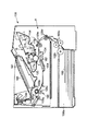
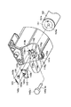
図2を用いて、前述したカートリッジBを用いる電子写真画像形成装置100について説明する。図2は、電子写真画像形成装置(以下、「画像形成装置」と称す。)100の構成図である。
(2) Description of Electrophotographic Image Forming Apparatus The electrophotographic
尚、以下、画像形成装置100として、レーザービームプリンターを例に挙げて説明する。
Hereinafter, a laser beam printer will be described as an example of the
画像形成時に、回転する感光体ドラム107の表面を帯電ローラ108によって一様に帯電する。次いで、レーザーダイオード、ポリゴンミラー、レンズ、反射ミラー(いずれも不図示)を有する光学手段101から画像情報に応じたレーザ光を感光体ドラム107へ照射する。これによって、感光体ドラム107に画像情報に応じた静電潜像を形成する。この潜像は、前述した現像ローラ110によって現像される。
At the time of image formation, the surface of the rotating
一方、現像剤像の形成と同期して、カセット103aにセットした記録媒体102を送り出しローラ103b、搬送ローラ対103c、103d、103eによって転写位置へ搬送する。転写位置には、転写手段としての転写ローラ104が配置されている。そしてこの転写ローラ104に電圧を印加する。これによって、感光体ドラム107上の現像剤像を記録媒体102に転写する。
On the other hand, in synchronization with the formation of the developer image, the
現像剤像の転写を受けた記録媒体102は、ガイド103fを介して定着手段105へ搬送される。定着手段105は、駆動ローラ105c、及び、ヒータ105aを内蔵した定着ローラ105bを備えている。そして、定着手段105を通過する記録媒体102に熱及び圧力を印加する。これによって、現像剤像を記録媒体102に定着する。記録媒体102は、その後、ローラ対103g、103hで搬送され、トレイ106へ排出される。前記ローラ103b、搬送ローラ対103c、103d、103e、ガイド103f、及び、ローラ対103g、103h等が記録媒体102の搬送手段103を構成する。
The
カートリッジBの装置本体Aに対する着脱は、次のように行われる。 The cartridge B is attached to and detached from the apparatus main body A as follows.
図3に示すように、操作者によって、装置本体Aに設けられたドア109を開く。そして、カートリッジBを装置本体Aに設けたカートリッジ装着手段130に対して取り外し可能に装着する。
As shown in FIG. 3, the operator opens the
図4及び図5に示すように、本実施例の装着手段130は、装置本体Aに設けた本体ガイド130R1、130R2、130L1、130L2を有する。カートリッジBを装置本体Aに装着する際は、カートリッジガイド140R1、140R2(図6)を、本体ガイド130R1、130R2に沿って、また、カートリッジガイド140L1、140L2(図7)を本体ガイド130L1、130L2に沿って、カートリッジ装着部130aに装入する。
As shown in FIGS. 4 and 5, the mounting means 130 of the present embodiment includes body guides 130R1, 130R2, 130L1, and 130L2 provided in the apparatus body A. When the cartridge B is mounted on the apparatus main body A, the cartridge guides 140R1 and 140R2 (FIG. 6) are moved along the main body guides 130R1 and 130R2, and the cartridge guides 140L1 and 140L2 (FIG. 7) are moved to the main body guides 130L1 and 130L2. Then, the cartridge is inserted into the
そして、カートリッジガイド140R1が本体ガイド130R1の位置決め部130R1aに嵌合して、また、カートリッジガイド140R2が本体ガイド130R2の位置決め部130R2aに載置される。そして、カートリッジガイド140L1が本体ガイド130L1の位置決め部130L1aに嵌合して、また、カートリッジガイド140L2が本体ガイド130L2の位置決め部130L2aに載置される。このように、カートリッジBは、装着手段130によって、カートリッジ装着部130aに取り外し可能に装着される。カートリッジBは、カートリッジ装着部130aに装着されることによって画像形成動作が可能となる。ここで、カートリッジ装着部130aとは、前記装着手段130によって、装置本体Aに装着されたカートリッジBが占める空間のことである。
The cartridge guide 140R1 is fitted to the positioning portion 130R1a of the main body guide 130R1, and the cartridge guide 140R2 is placed on the positioning portion 130R2a of the main body guide 130R2. The cartridge guide 140L1 is fitted into the positioning portion 130L1a of the main body guide 130L1, and the cartridge guide 140L2 is placed on the positioning portion 130L2a of the main body guide 130L2. In this manner, the cartridge B is detachably mounted on the
尚、カートリッジBが装着される際には、駆動力伝達部としてのカップリング134(図5)は退避しており、カートリッジBの装着に邪魔になることはない。因みに、カバー109を閉じると、駆動力受け部としてのカートリッジBのカップリング107a(図6)と、装置本体A側の前記カップリング134は連結する。そして、装置本体Aから、感光体ドラム107を回転させるための駆動力を受ける。
When the cartridge B is mounted, the coupling 134 (FIG. 5) as the driving force transmission unit is retracted and does not interfere with the mounting of the cartridge B. Incidentally, when the
(3)カートリッジ帯電接点部材
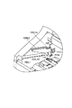
図10に示すように、ドラムユニット120には装置本体Aから帯電ローラ108に帯電バイアス電圧を印加するための入力電気接点部材、即ち、カートリッジ帯電接点部材141が設けられている。カートリッジ帯電接点部材141はドラム枠体118に取り付けられている。具体的には、前記帯電接点部材141は、装置本体Aの出力電気接点部材、即ち、本体帯電接点部材144の電気接点(出力電気接点)144a(図13)と接触するために前記帯電接点部材141の一部である接点141aがドラム枠体118の側面に配置されている。また、カートリッジ帯電接点部材141の他端部はドラムユニット120の内部で帯電ローラ108に電気的に接続されている。
(3) Cartridge Charging Contact Member As shown in FIG. 10, the
図11は、ドラム枠体118の内部が見えるように、ドラム枠体118の側面を切断した図である。図示するように、帯電ローラ108は、金属軸108aを、導電性の樹脂で成型された帯電ローラ軸受132に回転可能に支持されている。そして、帯電ローラ108は、ドラム枠体118に取り付けられている。また、帯電ローラ軸受132とドラム枠体108の間には帯電ローラ加圧ばね133が取り付けられている。前記ばね133は、帯電ローラ108を所定の力で感光体ドラム107に押し付けている。
FIG. 11 is a view in which the side surface of the
前記帯電接点部材141は、装置本体に設けられた電気接点144aと接触するための電気接点141aと、前記ばね133と接触するための接点141bとを有する一体的な板金で形成されている。前記板金(帯電接点部材141)は、ドラム枠体118に取り付けられている。したがって、前記接点141aは、前記接点141b、前記ばね133、帯電ローラ軸受132、金属軸108aを介して帯電ローラ108と電気的に接続されている。
The charging
前記電気接点141aは、ドラム枠体118の側面から突出しないように、周囲をリブ118gで囲まれた面に配置されている(図12)。
The
(4)カートリッジ可動部材
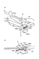
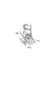
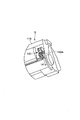
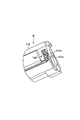
次に、図10、図12、図19、図20を用いて、カートリッジBに取り付けられる可動作動部材、即ち、カートリッジ可動部材142の構成について説明する。図12は、カートリッジ可動部材142等をドラム枠体118へ取り付ける取り付け方法を示す図であり、図10は、図12に示すように取り付けた後の状態を表わす図である。図19は、前記可動部材142の主要部の構成のみを抜き出して表わした側面図である。図20は、前記可動部材142の構成の主要部の構成を分かり易くするために適宜断面をとって表わした構成説明図である。
(4) Cartridge movable member Next, the configuration of the movable operation member attached to the cartridge B, that is, the cartridge
本実施例の構成の概要を簡単に述べる。 An outline of the configuration of this embodiment will be briefly described.
前記可動部材142の動作は、所謂「トグル」の動作を応用するものである。即ち、バネによる釣り合いの位置から少しでもずれるとそのずれた向きに回転付勢される。そして、安定の位置から釣り合いの位置を越えさせる動きを感光体ドラム107と一体となって動くフランジ151に設けた偏心軸151bにより行う(図12)。
The operation of the
図12に示すように、感光体ドラム107には、その端部にフランジ151が固着されている。フランジ151には穴部151aが設けてある。カートリッジガイド円筒部140L1の小径部140L1aをドラム枠体118に設けたドラム支持穴118jに貫通させる。そして、前記小径部140L1aをフランジ151の穴部151aに嵌め込む。前記小径部140L1aと前記ドラム支持穴118jは、圧入になるように寸法を設定している。これによって、前記円筒部140L1をドラム枠体118に固定する。また、フランジ151には偏心軸151bが設けてある。これにより、前記フランジ151は、感光体ドラム107の回転と共に小径部140L1aを中心に回転する。
As shown in FIG. 12, a
図12に示すように、前記可動部材142は、その穴142aを同軸線上に円柱を連ねた形状(段軸)の止め軸150が貫通する。さらに止め軸150をドラム枠体118の側面の止め穴118iに圧入する。これにより、前記可動部材142は、前記止め軸150の周りに回動可能に取り付けられる。止め軸150は、可動部材142の脱落防止のため大径部150aを有する。可動部材142を組み込む際には、その突き当て部142bが、ドラム枠体118の側面に設けられた開口部118hに入るように組み込む。従って、可動部材142の回転範囲は、矢印aの向きに動いた時は突き当て部142bが突き当て部118eに突き当たるまで、また、矢印bの向きに動いた時は突き当て部142bが突き当て部118fに突き当たるまでである。このように、可動部材142の回転範囲は前記範囲に規制される。尚、前記突き当て部118e、118fは、ドラム枠体118に設けられている。
As shown in FIG. 12, the
また、前記突き当て部142bは、前記開口部118hを貫通しさらに内側へと突出する。図20に示すように、その突出量は、感光体ドラム107の中心軸方向においてフランジ151の偏心軸151bと重なる領域までである。尚、偏心軸150bと可動部材142は係合して動くが、その動きについては後述する。
The abutting
可動部材142のバネかけ部142eに、弾性作用部材としての引っ張りコイルばね143の一端143aを取り付け、もう一方の端部143bをドラム枠体118の側面の突軸118kに取り付ける。図20に示すように、前記バネかけ部142e及び突軸118kは、ばね143をかける部分の外側にばね143の外径よりも大きな大径部118k1を有する。これによって、ばね143が外れるのを防止している。可動部材142が可動範囲内で動いた場合に、ばね143には常に圧縮する向きの力が発生するようにばね143は十分延ばした状態で使用する。
One
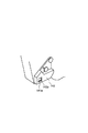
(5)カートリッジ可動部材142の動作の説明
図19及び図20を参照して、上記組み付けが終了した後の可動部材142とフランジ151の動きについて説明する。
(5) Description of Operation of Cartridge
先ず、可動部材142の「トグル」の動きについて説明する。
First, the “toggle” movement of the
図19(a)、(b)においては、可動部材142の回転中心(止め軸150の中心)は、バネかけ部142eの中心と突軸118kの中心を結ぶ線より上方にある。従って、この状態においては、ばね143のバネ力によるモーメントにより、可動部材142は矢印aの向きに付勢されている。そして、突き当て部142b(図19(a)〜(d))において破線で示してある)がドラム枠体118の突き当て部118eに突き当たる。これによって、可動部材142は、回転方向の位置決めがなされている。尚、図19(a)は、図10図と同じ状態を表わしている。
19A and 19B, the rotation center of the movable member 142 (the center of the stop shaft 150) is above the line connecting the center of the
図19(c)においては、可動部材142の回転中心(止め軸150の中心)が丁度バネかけ部142eの中心と突軸118kの中心を結ぶ線上にある。従って、この状態においては、可動部材142を回転中心(止め軸150の中心)の回りに回転させようとする、前記バネ力によるモーメントは発生しない。これが釣り合いの位置である。このとき前記突き当て部142bは、前記突き当て部118e、118fのいずれにも接触していない。
In FIG. 19C, the rotation center of the movable member 142 (the center of the stop shaft 150) is just on the line connecting the center of the
図19(d)においては、可動部材142の回転中心(止め軸150の中心)は、バネかけ部142eの中心と突軸118kの中心を結ぶ線より下方にある。従って、この状態においては、前記バネ力によるモーメントにより、可動部材142は矢印bの向きに付勢される。そして、突き当て部142bがドラム枠体118の突き当て部118fに突き当たる。これによって、可動部材142は回転方向の位置決めがなされる。
In FIG. 19D, the rotation center of the movable member 142 (the center of the stop shaft 150) is below the line connecting the center of the
次に、感光体ドラム107の回転により可動部材142が移動する構成を説明する。
Next, a configuration in which the
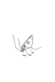
図19(a)に示すように、前記突き当て部142bと離れた位置にあるフランジ151の偏心軸(突起)151b(図19(a)、(b)においては破線で示してある)は、装置本体Aから駆動力が伝達され感光体ドラム107が図中時計回りに回転するのと連動して回転する。このように、偏心軸151bは、感光体ドラム107とともに回転する。そして、図19(b)に示すように、偏心軸151bは、突き当て部142bと接触する位置に移動する。尚、突起としての前記偏心軸151bは、感光体ドラム107の一部であるフランジ151から、ドラム軸線方向へ突出して設けられている。
As shown in FIG. 19 (a), the eccentric shaft (protrusion) 151b (shown by a broken line in FIGS. 19 (a) and (b)) of the
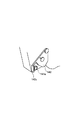
さらに感光体ドラム107が回転すると、可動部材142は偏心軸151bに押されて矢印bの向きに回転する。そして、前述した通り、可動部材142は図19(c)に示した釣り合いの位置に到達する。さらに感光体ドラム107が回転すると、前記偏心軸151bに押されて、可動部材142は、釣り合いの位置を越える。釣り合いの位置を越えると、前記可動部材142は前記ばね143の弾性力によって矢印bの向きに回転して、突き当て部142bが前記突き当て部118fに突き当たって止まった状態となる(図19(d))。この状態において、感光体ドラム107がさらに回転しても、突き当て部142bは偏心軸151bが通過する領域の外に位置するので再び接触することはない。従って、可動部材142は、図19(d)の状態を維持する。
When the
即ち、前記作動部材142はカートリッジ枠体としてのドラム枠体118に軸150を中心にして相対的に移動可能に設けられている。そして、前記装置本体Aから前記カートリッジBに伝達された駆動力によって前記感光体ドラム107が回転する。そして、前記駆動力は前記感光体ドラム107の回転によって前記作動部材142に伝達される。これによって、前記作動部材142は前記ドラム枠体118に対して相対的に回転移動する。また、前記作動部材142に弾性力を作用するバネ143を有する。そして、前記弾性力は前記作動部材142の前記回転移動に寄与する。具体的には、前記作動部材142は前記駆動力によって回転する前記感光体ドラム107に設けられた突起としての偏心軸151bによって押されて回転する(図19(c))。そして、前記作動部材142は前記偏心軸151bによって押されて、前記バネ143の弾性力による回転モーメントが釣り合う位置を越えた位置まで回転すると前記偏心軸151bから離れる(図19(d))。そして、前記作動部材142は前記バネ143の前記弾性力によって回転を始める。そして、前記作動部材142の前述一連の回転動作によって、前記電気接点144aを前記退避位置から前記電気接続位置に移動させる。
In other words, the operating
(6)装置本体Aに設けられた帯電接点
次に、装置本体Aに設けられた出力電気接点部材である本体帯電接点部材144について説明する。
(6) Charging contact provided in apparatus main body A Next, the main body charging
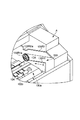
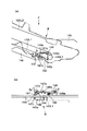
図13に示すように、装置本体Aの内側の側面には、カートリッジBの入力電気接点部材であるカートリッジ帯電接点部材141の接点141aと接触して帯電バイアス電圧を印加するための本体帯電接点部材144が設けられている。カートリッジBが装置本体Aに装着されていない状態では、本体帯電接点部材144の接点144aは、装置本体Aの内側板145から突出しない位置に退避している。本体帯電接点部材144は、リード線等により装置本体A内部の高圧電気回路(後述する)に接続している。
As shown in FIG. 13, a main body charging contact member for applying a charging bias voltage in contact with a
また、装置本体Aの内部には、固定部材146が内側板145から突出して設けられている。前記固定部材146は、装置本体AからカートリッジBを取り出す際に前記可動部材142と突き当たる。即ち、前記固定部材146は、前記可動部材142を回動させて釣り合いの位置を越えて元の位置に戻すための突き当て部となる。そして、カートリッジBの装着方向において、前記固定部材146よりも下流側には、本体可動部材147の一端部147cが突出している。尚、前記固定部材146は、前記カートリッジBを前記装置本体Aに装着する際には、前記可動部材142と接触しない。よって、前記固定部材146は、前記可動部材142を回動させない。
Further, a fixing
本体可動部材147は、カートリッジ可動部材142の回転動作と連動して矢印c、d方向に動く。図13(b)に示すように、装置本体AにカートリッジBを装着し画像形成の準備ができた後に感光ドラム107が回転すると、前記本体可動部材147が前記可動部材142によって矢印c方向に押される。また、本体可動部材147の動作と連動して、前記帯電接点144aが内側板145から装着部130aの方向へ回動移動して突出する。そして、前記接点144aは、カートリッジBの有する前記接点141aと接触する。これによって、帯電ローラ108に装置本体Aから電圧を印加することが可能となる。即ち、電気接続位置に静止して待機している前記接点141aに対して、前記接点144aが回動移動して接触する。そして、前記接点144aは、前記接点141aと接触した後、前記接点141aに対して摺動する。従って、両接点間に付着するゴミ、現像剤等を除去することができる。よって、両接点の電気的接続の信頼性を向上させることができた。
The main body
(7)装置本体Aの内部構成
ここで、図14を用いて、装置本体Aの内部構成について説明する。図14は、装置本体Aを手前側D、即ち、カートリッジBを装着する側D(図3)から装着方向Xへ向かって見た内部正面図である。
(7) Internal Configuration of Device Main Body A Here, the internal configuration of the device main body A will be described with reference to FIG. FIG. 14 is an internal front view of the apparatus main body A viewed from the front side D, that is, the side D (FIG. 3) on which the cartridge B is mounted in the mounting direction X.
装置本体Aの底面、即ち、カートリッジ装着部130aの下方には、エンジンコントローラ回路基板EC(図21)が配置されている。また、前記装着部130aの一端側であって、内側板145の内側側面145eの外側には、モータM、及び、モータMの駆動力を例えばカップリング134等に伝達する駆動ギア列(駆動力伝達手段)M1が配置されている。
An engine controller circuit board EC (FIG. 21) is disposed on the bottom surface of the apparatus main body A, that is, below the
また、前記装着部130aの他端側には、前述した通り、前記カートリッジBが前記装置本体Aに挿入される挿入方向Xにおいて、前記可変位係合部147cが前記固定部材146よりも下流側に設けられており、かつ、前記挿入方向Xにおいて、少なくとも前記係合部147cの一部が固定部材146と重なっている。即ち、前記挿入方向Xにおいて、前記固定部材146の背面に、前記係合部147cの一部が位置している。
Further, as described above, in the insertion direction X in which the cartridge B is inserted into the apparatus main body A, the variable
従って、操作者が装置本体Aのメンテナンス(例えば、ジャム処理等)のために、カートリッジBを取り外した装置本体A内へ、手前側Dから手を挿入したとしても、前記固定部材146に遮られる。従って、操作者が不用意に可変位係合部147cに触れることを防止できる。これによって、退避位置に退避している出力電気接点144a(図15では図示を省略)が、電気接続位置に不用意に移動することを抑止できる。
Therefore, even if the operator inserts a hand from the front side D into the apparatus main body A from which the cartridge B has been removed for maintenance of the apparatus main body A (for example, jam processing), the fixing
(8)可動部材と帯電接点部材の動作の説明
次に、図15〜図18を参照して、カートリッジBのカートリッジ可動部材142と装置本体Aの本体帯電接点部材144の動作について更に説明する。図15は、カートリッジBを装置Aに装着する途中の動作を説明し、図16〜図18は、装着後の動作を説明するための模式図である。
(8) Description of Operation of Movable Member and Charging Contact Member Next, the operation of the cartridge
図15(a)、図16(a)、図17(a)、図18(a)は、装置本体Aの内側板145を装置本体内部から見た図(図13の矢印Y方向から見た図)であり、図15(b)、図16(b)、図17(b)、図18(b)は、それぞれ、図15(a)、図16(a)、図17(a)、図18(a)を矢印Z方向から見た図である。
15 (a), 16 (a), 17 (a), and 18 (a) are views of the
各図に示すように、本体可動部材147は、内側板145の外側に軸部147aを中心として回動可能に取り付けられている。本体帯電接点部材144は、接点支持部材148に取り付けられている。前記接点支持部材148は、軸部148aを中心として回動可能に取り付けられ、弾性機能部材としての圧縮ばね149によって矢印e方向に付勢されている。本体可動部材147と接点支持部材148は、互いの突き当て部147bと148bが当接しており、連動する。
As shown in each figure, the main body
接点支持部材148が矢印e方向に付勢されると、本体可動部材147は、矢印f方向に回転する。そして、本体可動部材147は、突き当て部(不図示)が内側板145の開口145a1の縁部に突き当たることで位置決めされる。このとき、前記接点144aは、内側板145の開口145a2から装置本体A内部に突出しない位置であって、カートリッジBとの電気的接続位置から退避する退避位置に位置している。
When the
図15は、カートリッジBを装置本体Aに装着する途中の状態を示す図である。カートリッジBは、装着ガイド部130L1、130L2に沿って矢印X方向に装着される。装着途中では前記可動部材142は、先に述べた図19(a)の位置にある。また、前記接点144aは、前述したように内側板145の開口145a2から突出しない位置となっている。そして、図16に示す通り、カートリッジBの装置本体Aに対する装着が完了した状態では、前記可動部材142は、まだ本体可動部材147と接触していない。
FIG. 15 is a diagram illustrating a state in the middle of mounting the cartridge B to the apparatus main body A. The cartridge B is mounted in the arrow X direction along the mounting guide portions 130L1 and 130L2. During the mounting, the
カートリッジBを装着完了後カートリッジドア109(図3)を閉じると、画像形成装置100が画像形成の準備に入る。
When the cartridge door 109 (FIG. 3) is closed after the cartridge B is completely installed, the
そして、装置本体Aが動作を開始し、駆動力が伝達されて感光体ドラム107が回転する。すると、図19(a)に示す通り、前記突き当て部142bと離れた位置にあった前記偏心軸151bは、感光体ドラム107とともに回転する。そして、図19(b)に示すように、前記偏心軸151bは、前記突き当て部142bと接触する。その後は先に説明した通り、前記可動部材142は、図19(c)に示す位置を通過して図19(d)の位置まで回転する。
Then, the apparatus main body A starts operating, the driving force is transmitted, and the
図17及び図18を参照して、前記可動部材142の動作を説明する。可動部材142は、図16の状態から矢印kの向きに回転する。そして、図17に示すように、可動部材142の係合部142dが本体可動部材の一端147cに接触する。さらに、可動部材142が矢印kの向きに回転すると、可動部材142の係合部142dが本体可動部材147を押す。これによって、本体可動部材147が矢印g方向に回転する。これにより、接点支持部材148が矢印h方向に回転する。これによって、前記接点144aが内側板145の開口145a2から装置本体A内側に突出してくる。そして、可動部材142が図19(d)に示した状態と同じである図18の位置まで回転する間に、前記係合部142dがさらに本体可動部材147を矢印g方向に回転させる。そして、これと連動して本体帯電接点144aはさらに内側板145から突出し、カートリッジBが有する接点141aと接触する。
The operation of the
前述した通り、本実施例によれば、カートリッジBが装着部130に装着されて、カートリッジBが静止した状態で接点141aと接点144aを接触させることができる。従って、両接点の電気的接続をより確実に行うことができる。
As described above, according to the present embodiment, the
以上説明したように、本実施例においては、カートリッジBの装置本体Aに対する装着が完了して、感光体ドラム107が回転を開始すると、カートリッジ可動部材142と本体可動部材147、接点支持部材148の動作によって前記電気接点144aが装置本体A内部に突出して電気接点141aと接触する。そして、CPU200(図21)の制御によって、電源S(図21)からの電圧が前記電気接点144a、及び、電気接点141aを介して帯電ローラ108に供給される。前述した通り、前記出力電気接点144aは、電気接続位置と、前記電気接続位置から退避して、前記カートリッジ装着部130外に位置する退避位置との間を移動可能に設けられている。そして、前記出力電気接点144aは、前記電源Sと前記電源回路Eを介して電気的に連結されている。また、前記入力電気接点141aは、前記電気接続位置に位置せしめられた前記出力電気接点144aに係合する。そして、前記プロセス手段としての現像ローラ110及び/又は帯電ローラ108が作動するための電圧を受け入れる。
As described above, in this embodiment, when the mounting of the cartridge B to the apparatus main body A is completed and the
即ち、本実施例によれば、静止状態で前記電気接続位置に位置した前記電気接点141aに対して、前記電気接点144aが移動して接触する。従って、両電気接点の接触をより確実に行うことができる。このようにして、前記プロセス手段としての帯電ローラ108が作動するための電圧を装置本体Aから受ける。
That is, according to the present embodiment, the
これにより装置本体Aから帯電ローラ108に帯電バイアスを印加可能となる。
As a result, a charging bias can be applied from the apparatus main body A to the charging
また、装置本体AからカートリッジBを取り出す際には、前記可動部材142が前記固定部材(突き当て部)146と係合する。このように、前記可動部材142は前記固定部材146と係合することによって回動して、前述した釣り合いの位置を越えて再び元の位置(図19(a)に示す位置)へ戻る。図13に示すように、この可動部材142の動きに連動して、本体可動部材147が矢印dの向きに動く。従って、本体帯電電気接点144aは、本体内部に突出した状態から再び図13(a)及び図15(a)、(b)に示すように退避した状態となる。
Further, when the cartridge B is taken out from the apparatus main body A, the
(9)エンジンコントローラ回路基板(電源回路)
ここで、図21を用いて、本実施例に用いられる、装置本体Aに実装された、電源回路としてのエンジンコントローラ回路基板ECについて説明する。この回路基板ECは、前記カートリッジ装着部130aの下方に実装されている。そして、前記回路基板ECは、CPU200、及び、電源回路Eを有している。
(9) Engine controller circuit board (power supply circuit)
Here, an engine controller circuit board EC as a power supply circuit mounted on the apparatus main body A used in the present embodiment will be described with reference to FIG. The circuit board EC is mounted below the
また、前記回路基板ECには、即ち、前記電源回路Eには、電源Sが接続されている。そして、電源回路Eは、帯電バイアス回路E1、現像バイアス回路E2、及び、転写帯電バイアス回路E3を有する。 Further, a power source S is connected to the circuit board EC, that is, to the power circuit E. The power supply circuit E includes a charging bias circuit E1, a developing bias circuit E2, and a transfer charging bias circuit E3.
ここで、帯電バイアス回路E1は、負のDC電圧とAC電圧を生成する。そして、帯電ローラ108に前記各電圧を重畳した電圧を印加する。帯電ローラ108はこの電圧を受けて作動して、感光体ドラム107を帯電する。
Here, the charging bias circuit E1 generates a negative DC voltage and an AC voltage. Then, a voltage obtained by superimposing the voltages is applied to the charging
尚、帯電バイアス回路E1は、駆動ローラ105cを介して定着ローラ105bにも負のDC電圧を印加する。また、現像バイアス回路E2は、負のDC電圧とAC電圧を生成する。そして、現像ローラ110に前記各電圧を重畳した電圧を印加する。現像ローラ110はこの電圧を受けて作動して、現像剤を用いて静電潜像を現像する。また、転写バイアス回路E3は、正又は負のDC電圧を生成する。そして、転写ローラ104に正又は負のDC電圧を印加する。
The charging bias circuit E1 also applies a negative DC voltage to the fixing
このように、帯電ローラ108には、帯電バイアス回路E1を介して電源Sからの電圧が供給される。また、定着ローラ105b及び駆動ローラ105cにも、帯電バイアス回路E1を介して電源Sからの電圧が供給される。更に、現像ローラ110には、現像バイアス回路E2を介して電源Sからの電圧が供給される。また、転写ローラ104には、転写帯電バイアス回路E3を介して電源Sからの電圧が供給される。
Thus, the voltage from the power source S is supplied to the charging
これらの回路E1、E2、E3は、前記回路基板EC上に設けられたCPU200からの指示によりそのオン、オフ等が制御される。
These circuits E1, E2, and E3 are controlled to be turned on / off by an instruction from the
以上説明した通り、本実施例によれば、装置本体AからカートリッジBを取り外した状態で、操作者がジャム処理(万一、記録媒体102が装置本体A内で詰まってしまった場合に、詰まってしまった記録媒体102を装置本体A内から取り出すこと)を行うために手を装置本体A内へ侵入させた場合であっても、前記手が装置本体に設けられた出力電気接点144aに触れることがない。前記出力電気接点144aが退避位置に退避しているからである。従って、(1)出力電気接点144aに異物(例えば前記手に付着した現像剤グリス、或いは、人の汗等)が付着することがない。因みに、装置本体A内の部品に付着しているグリス、或いは、現像剤が、ジャム処理中に手に付着してしまい、これが出力電気接点144aに付着することが希に発生する恐れがある。或いは、(2)出力電気接点144aを損傷することがない。或いは、人体に帯電している静電気が静電ノイズとして前記手から出力電気接点144aに印加されることを防止できる。これによって、(3)装置本体Aに実装された電源回路E(図21)の素子が破損することを未然に防止できる。(4)電気接続位置に静止して待機している前記接点141aに対して、前記接点144aが回動移動して接触する。そして、前記接点144aは、前記接点141aと接触した後、前記接点141aに対して摺動する。従って、両接点間に付着するゴミ、現像剤等を除去することができる。よって、両接点の電気的接続の信頼性を向上させることができた。
As described above, according to the present embodiment, the jamming process is performed by the operator with the cartridge B removed from the apparatus main body A (if the
従って、上記(1)〜(4)によって、電源S(図21)から帯電ローラ108へ電圧を印加する際に、導通不良が発生することを防止できる。 Therefore, according to the above (1) to (4), it is possible to prevent a conduction failure from occurring when a voltage is applied from the power source S (FIG. 21) to the charging roller.
更に、前述した通り、本体可動部材とされる前記可変位部材147の係合部147cが前記固定部材146よりもカートリッジ挿入方向Xにおいて下流側に配置されており、また、前記挿入方向Xにおいて、前記係合部147cの少なくとも一部が前記固定部材146と重なっている。即ち、前記挿入方向Xにおいて、前記係合部147cの少なくとも一部が前記固定部材146の背面に位置している。従って、ジャム処理等のメンテナンスのために、装置本体A内へ操作者が手或いは工具等を進入させたとしても、前記固定部材146に邪魔されて、前記手或いは工具等が前記係合部147cに触れることがない。
Furthermore, as described above, the engaging
従って、退避位置に退避している出力電気接点144aが電気接続位置へ不用意に移動することを防止できる。
Therefore, it is possible to prevent the output
つまり、前述した実施例によれば、次の効果を達成することができる。
(1)画像形成装置本体からプロセスカートリッジを取り出した状態で、操作者がジャム処理等を行うために手を画像形成装置本体内に挿入した場合であっても、電気接点が内側面から突出していないので、電気接点に触れにくい。更に、操作者が画像形成装置本体にカートリッジを装着する方向に見たときに、電気接点を突出させる本体可動部材が、固定された本体係合部の背面にあるので、操作者が本体可動部材に触れにくい。これにより、電気接点に、静電ノイズが印加されることがなく、装置本体に実装された電気回路上の素子の破壊を防止することができる。また、接点に人の汗や本体内のグリス等が付着し、導通不良が発生することを防止できる。
(2)操作者がカートリッジを画像形成装置に装着する際に、電気接点同士の抵抗がない。従って、カートリッジを画像形成装置によりスムーズに装着することができる。
(3)画像形成装置本体の構成上、駆動側とは反対側に接点部材を設けている。これによって画像形成装置本体のスペースを有効に活用でき、装置を小型化することができる。
(4)カートリッジ可動部材をプロセスカートリッジの側面に設けているので組立性が良い。
(5)プロセスカートリッジのカートリッジ接点部材がプロセスカートリッジの枠体の表面から突出しない位置に配置されている。従って、操作者がカートリッジの取り扱い時に電気接点に容易に触れることを抑止できる。これにより、カートリッジの電気接点に人の汗やグリス等が付着し、導通不良が発生することを防止できる。
That is, according to the embodiment described above, the following effects can be achieved.
(1) Even when the operator inserts his / her hand into the image forming apparatus main body to perform jam processing or the like with the process cartridge removed from the image forming apparatus main body, the electrical contacts protrude from the inner side surface. Because there is no, it is difficult to touch the electrical contacts. Further, since the main body movable member for projecting the electrical contact is located on the back surface of the fixed main body engaging portion when the operator looks in the direction of mounting the cartridge on the main body of the image forming apparatus, the operator can move the main body movable member. It is hard to touch. Thereby, electrostatic noise is not applied to the electrical contact, and destruction of elements on the electrical circuit mounted on the apparatus main body can be prevented. In addition, it is possible to prevent the occurrence of poor conduction due to adhesion of human sweat or grease in the main body to the contact points.
(2) There is no resistance between the electrical contacts when the operator mounts the cartridge on the image forming apparatus. Therefore, the cartridge can be mounted smoothly by the image forming apparatus.
(3) Due to the configuration of the image forming apparatus main body, a contact member is provided on the side opposite to the drive side. As a result, the space of the image forming apparatus main body can be used effectively, and the apparatus can be miniaturized.
(4) Since the cartridge movable member is provided on the side surface of the process cartridge, it is easy to assemble.
(5) The cartridge contact member of the process cartridge is disposed at a position where it does not protrude from the surface of the process cartridge frame. Therefore, it is possible to prevent the operator from easily touching the electrical contacts when handling the cartridge. As a result, it is possible to prevent a person's sweat, grease, or the like from adhering to the electrical contacts of the cartridge, resulting in poor conduction.
なお、上記実施例ではカートリッジ可動部材142を移動させるのに感光体ドラム107の回転を利用したが、本発明は、これに限定されるものではない。例えば現像ローラ110の回転を利用して同様に構成しても良い。
In the above embodiment, the rotation of the
また、上記実施例では、カートリッジBが装置本体Aに装着された際、プロセス手段としての帯電部材、即ち、帯電ローラ107に対して、出力電気接点としての帯電出力電気接点144a、及び、入力電気接点としての帯電入力電気接点141aを介して、装置本体100から電圧を受ける構成であるとして説明した。しかしながら、本発明はこれに限定されるものではない。上記実施例にて説明したと同様の構成により、例えば、カートリッジBが装置本体Aに装着された際、現像ローラ110に対して、出力電気接点としての現像出力電気接点(不図示)、及び、入力電気接点としての現像入力電気接点(不図示)を介して、装置本体100から電圧を受ける構成とすることもできる。また、帯電ローラ108及び現像ローラ110の双方に電圧を供給すること可能である。即ち、プロセス手段を機能させることができる。
In the above embodiment, when the cartridge B is mounted on the apparatus main body A, the charging output
従って、以下に説明する実施例においても、帯電ローラ108或いは現像ローラ110に関連して本発明を説明するが、これに限定されるものではなく、同様の構成を採用して、他のプロセス手段に対しても、装置本体100からの電圧供給が可能である。
Therefore, in the embodiments described below, the present invention will be described in relation to the charging
実施例2
次に、図22〜図26を参照して本発明の第二の実施例について説明する。
Example 2
Next, a second embodiment of the present invention will be described with reference to FIGS.
本実施例においても、カートリッジB及び画像形成装置100の構成は、図1及び図2を参照して実施例1で説明したと同様の構成とされる。従って、本実施例では、前述した実施例と異なる構成部分について説明し、同様の構成、機能を有する部材については同一の参照番号を付して先の実施例の説明を援用する。
Also in this embodiment, the configurations of the cartridge B and the
前述した実施例1では、ドラム枠体に設けたリブ118gにより電気接点141aを保護している。しかしながら、本実施例では、ドラム枠体に設けたリブ118gではなく、カートリッジ可動部材142によって前記電気接点141aを保護している。この点が、本実施例が実施例1と異なる点である。
In the first embodiment described above, the
具体的には、前記電気接点141aを前記カートリッジ可動部材142の裏側に配置している。これによって、前記可動部材142でもって前記接点141aを覆っている。その他の構成及び動作については前述の実施例1と同様の構成であり、特に説明のない部分は実施例1と同じである。
Specifically, the
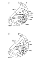
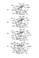
図22(a)〜(d)は、本実施例2のカートリッジ可動部材142の構成の主要部を表わす側面図である。図22(a)、(b)、(c)、(d)の状態は、それぞれ、実施例1の図19(a)、(b)、(c)、(d)に相当する。図23(a)、(b)は、カートリッジBを装置Aに装着する途中の状態を、図24(a)、(b)〜図26(a)、(b)は装着後の動作を説明するための模式図である。
22A to 22D are side views showing the main part of the configuration of the cartridge
図23(a)、図24(a)、図25(a)、図26(a)は、装置本体Aの内側板145を装置本体内部から見た図(図13の矢印Y方向から見た図)であり、図23(b)、図24(b)、図25(b)、図26(b)は、それぞれ、図23(a)、図24(a)、図25(a)、図26(a)を矢印Z方向から見た図である。つまり、図23(a)、(b)〜図26(a)、(b)の状態は、それぞれ、図15(a)、(b)〜図18(a)、(b)の状態に相当する。
23 (a), 24 (a), 25 (a), and 26 (a) are views of the
(1)カートリッジ帯電接点部材及びカートリッジ可動部材
実施例1の図19(a)の状態に相当する図22(a)を用いて説明する。前記電気接点141aは、前記可動部材142の背面に、前記可動部材142から露出しないように配置されている。よって、前記可動部材142は前記接点141aを保護している。
(1) Cartridge Charging Contact Member and Cartridge Movable Member A description will be given with reference to FIG. 22A corresponding to the state of FIG. The
(2)カートリッジ可動部材の動作の説明
カートリッジ可動部材142の「トグル」の動きは実施例1の場合と同じである。
(2) Description of Operation of Cartridge Movable Member The “toggle” movement of the cartridge
感光体ドラム107の回転により前記可動部材142は、矢印bの向きに回転する。そして、実施例1の図19(b)に相当する本実施例2の図22(b)の位置から、図19(c)に相当する図22(c)の位置を通過して、図19(d)に相当する図22(d)の位置まで移動する。
As the
図示するように、前記可動部材142が矢印bの向きに回転するに従って、前記電気接点141aは前記可動部材142から徐々に露出する。そして、図22(d)において、前記電気接点141aは完全に露出した状態となる。
As shown in the drawing, as the
(3)装置本体Aに設けられた帯電接点部材
装置本体Aに設けられる本体帯電接点部材144は実施例1と同様の構成であり、図13を用いて実施例1で既に説明した通りである。
(3) Charging contact member provided in apparatus main body A The main body charging
(4)可動部材と帯電接点部材の動作の説明
前記可動部材142の移動によって前記電気接点144aを画像形成装置本体A内部に突出させる。そして、前記電気接点144aを前記電気接点141aと接触させる構成は実施例1と同じである。
(4) Explanation of Operation of Movable Member and Charging Contact Member The
カートリッジBを装置Aに装着する前、図23(a)、(b)に示すカートリッジ装着途中、及び、図24(a)、(b)に示す装着直後においては、前記接点141aは、前記可動部材142によって覆われており、露出していない。即ち、前記接点141aは、前記可動部材142によって保護された状態にある。
Before the cartridge B is mounted on the device A, the
カートリッジBを装置本体Aに装着完了後、即ち、カートリッジBを装着部130に装着完了後、カートリッジドア109(図3)を閉じる。これによって、装置本体Aが画像形成の準備に入る。
After the cartridge B is completely attached to the apparatus main body A, that is, after the cartridge B is completely attached to the
装置本体Aが動作を開始し、駆動力が伝達されて感光体ドラム107が回転する。すると、前記可動部材142が図24(a)の位置から図25(a)の位置へと向かって矢印kの向きに回転する。これにより、前記接点141aを前記可動部材142から徐々に露出させる。それと共に、前記可動部材142は、可変位部材である本体可動部材147と接触する。そして、本体可動部材147は実施例1で説明した機構により、本体帯電部材144を装置本体Aの内部に向かって動かす。そして、前記接点141aが完全に露出した後に、静止状態にある前記電気接点141aに対して、前記電気接点144aが回動移動して接触を始める。そして、前記電気接点144aは最終的に図26(a)の位置まで移動して停止する。これにより装置本体AからカートリッジBの帯電ローラ108に帯電バイアスを印加可能となる。即ち、電気接続位置に静止して待機している前記接点141aに対して、前記接点144aが回動移動して接触する。そして、前記接点144aは、前記接点141aと接触した後、前記接点141aに対して摺動する。従って、両接点間に付着するゴミ、現像剤等を除去することができる。よって、両接点の電気的接続の信頼性を向上させることができた。
The apparatus main body A starts operating, the driving force is transmitted, and the
また、装置本体AからカートリッジBを取り出す際には、実施例1と同様に、前記可動部材142が前記固定部材146と係合する。そして、固定部材前記可動部材142は再び図23(a)、(b)の位置へ戻される。このカートリッジ可動部材142の動きに連動して本体可動部材147が矢印dの向きに移動する。これによって、電気接点144aが本体内部に突出した状態から再び図23(a)、(b)に示すように退避した状態となる。
Further, when the cartridge B is taken out from the apparatus main body A, the
カートリッジBが装置本体Aの外に取り出された際には、前記電気接点141aは、再びカートリッジ可動部材142で覆われる。
When the cartridge B is taken out of the apparatus main body A, the
上記構成とされる本実施例2もまた、前述した実施例1の作用効果と同様の作用効果を達成することができる。 The second embodiment configured as described above can also achieve the same function and effect as those of the first embodiment described above.
上記本実施例にて、可動部材142はカートリッジ接点部材141を完全に覆っていなくても良い。例えば、接点面より突出または一部を覆っていれば同様の効果を得ることができる。この「保護」の形態については実施例3において、次に、幾つか例を挙げて説明する。
In the present embodiment, the
実施例3
次に、図27〜図31を参照して本発明の第三の実施例について説明する。
Example 3
Next, a third embodiment of the present invention will be described with reference to FIGS.
本実施例においても、カートリッジB及び画像形成装置100の構成は、図1及び図2、更には図3〜図26を参照して実施例1、2で説明した構成と同様の構成である。従って、本実施例では、前述した実施例と異なる構成部分について説明し、上記実施例と同様の機能を有する部材については同一の参照番号を付して先の実施例の説明を援用する。
Also in this embodiment, the configurations of the cartridge B and the
上記実施例1では、前記電気接点141aは、図12に図示するように、前記接点141aの周囲をリブ118gで囲んでいる。これにより、前記接点141aがドラム枠体118の側面から突出しないようにしている。これにより、前記露出した接点141aに、操作者が誤って触れることを抑止している。また、実施例2では、前記接点141aが、前記カートリッジ可動部材142によって完全に覆われている。
In the first embodiment, as shown in FIG. 12, the
以下、操作者が前記接点141aに誤って触れるのを抑止できる前記可動部材142の他の構造を示す。
Hereinafter, another structure of the
図27から図31は、本実施例に係る可動作動部材であるカートリッジ可動部材142の種々の実施形態を示したものである。
27 to 31 show various embodiments of the cartridge
各図に示す実施形態において、前記ドラム枠体118の側面には、前記実施例1、2と同様に前記電気接点141aが配置されている。また、可動部材142も前述の実施例と同様に支持、位置決めされている。
In the embodiments shown in the drawings, the
図27に示す実施形態では、前記可動部材142は、実施例2と同様に、待機状態にて前記電気接点141aを覆った状態に位置決めされている。しかし、前記接点141aに対面した前記可動部材142には開口142pが設けられている。つまり、前記接点141aは、前記可動部材142にて覆われてはいない。しかしながら、前記接点141aの周囲に、前記接点141aの表面よりも高い前記可動部材142を配置されている。
In the embodiment shown in FIG. 27, the
図28に示す実施形態では、前記可動部材142に、待機状態にて前記接点141aの上部の一部を覆うようにしてリブ142qを設けている。
In the embodiment shown in FIG. 28, the
図29、図30、図31に示す実施形態では、前記ジ可動部材142に、待機状態にて前記電気接点141aの表面よりも高い突出部142r、142s、142tを前記接点141aの周囲の一部に設けている。
In the embodiment shown in FIGS. 29, 30, and 31, the
つまり、図29の実施形態では、前記突出部142rは、図面上、前記接点141aの下側に位置するよう、前記可動部材142に設けられている。また、図30の実施形態では、前記突出部142sは、図面上、前記接点141aの側部に位置するよう、前記可動部材142に設けられている。また、図31の実施形態では、前記突出部142tは、図面上、前記接点141aの下方角部に位置するよう、前記可動部材142に設けられている。
That is, in the embodiment of FIG. 29, the
本実施例によれば、実施例1、2の場合と同様に、いずれの実施形態の前記可動部材142においても、前記接点141aの近傍に前記接点141aよりも高い突出部(高い面)を設けた。そのため、操作者がカートリッジの取り扱い時に電気接点に不用意に触れることを抑止できる。これにより、カートリッジの有する電気接点に人の汗やグリス等が付着し、導通不良が発生することを防止できる。即ち、前記電気接点141aを保護することができる。
According to the present example, as in Examples 1 and 2, the
尚、本実施例においても、前述して上記実施例1、及び、実施例2の効果と同様の効果を達成することができる。 In this embodiment, the same effects as those of the first embodiment and the second embodiment can be achieved.
実施例4
次に、図32〜図35を参照して本発明の第四の実施例について説明する。
Example 4
Next, a fourth embodiment of the present invention will be described with reference to FIGS.
本実施例においても、カートリッジB及び画像形成装置100の構成は、図1及び図2を参照して実施例1で説明したと同様の構成である。従って、本実施例では、前述した実施例1、及び、実施例2と異なる構成部分について説明する。そして、同様の構成、機能を有する部材については同一の参照番号を付して、先の実施例の説明を援用する。
Also in this embodiment, the configurations of the cartridge B and the
つまり、上記実施例1、実施例2では、帯電電気接点を保護した。しかしながら、以下説明する本実施例では、現像電気接点を保護する場合を示す。実施例1、実施例2と異なる点は、前記可動部材142が保護する対象が帯電電気接点ではなくて、現像電気接点であることである。そして、可動部材142と係合して突出する装置に設けられた電気接点が、帯電バイアスを印加するための電気接点ではなくて、現像バイアスを印加するための電気接点である点である。
That is, in Example 1 and Example 2, the charged electrical contact was protected. However, in the present embodiment described below, a case where the developing electrical contact is protected is shown. The difference from the first and second embodiments is that the object to be protected by the
具体的には、実施例2に用いたのと同じ「トグル」機構を、感光体ドラム107の回転中心の周りに配置した。本実施例の基本動作は、実施例2と同様である。特に説明のない部分は実施例2と同じとし、実施例2で帯電電気接点を構成するものに付した符号と同じものを本実施例の現像電気接点を構成するものに関しても使用する。
Specifically, the same “toggle” mechanism as used in Example 2 was arranged around the rotation center of the
図32及び図33は、前記可動部材142の構成の主要部を表わす側面図である。図32及び図33に示す状態は、それぞれ、実施例2の図22(a)及び図22(d)の状態に相当する。図34(a)及び図34(b)の状態は、それぞれ、図13(a)及び図13(b)の状態に相当する。
32 and 33 are side views showing the main part of the configuration of the
図35は、カートリッジBを装置Aに装着する途中の動作を説明する、また、図36及び図37は、装着後の動作を説明するための図である。 FIG. 35 illustrates the operation in the middle of mounting the cartridge B to the apparatus A, and FIGS. 36 and 37 are diagrams for illustrating the operation after mounting.
図35(a)、図36(a)、図37(a)は、装置本体Aの内側板145を装置本体内部から見た図(図34の矢印Y方向から見た図)であり、図35(b)、図36(b)、図37(b)は、それぞれ、図35(a)、図36(a)、図37(a)を矢印Z方向から見た図である。つまり、図35(a)、(b)、図36(a)、(b)、及び図37(a)、(b)の状態は、それぞれ、図23(a)、(b)、図24(a)、(b)及び図26(a)、(b)の状態に相当する。
35 (a), 36 (a), and 37 (a) are views of the
(1)カートリッジ現像接点部材及びカートリッジ可動部材
図32(a)に示す状態においては、カートリッジ現像電気接点部材(入力電気接点部材)141の有する電気接点(入力電気接点)141aを、前記可動部材142の背面に配置している。そして、前記電気接点141aを、前記可動部材142から露出しないように配置している。これによって、前記接点141aを前記可動部材142によって保護している。尚、図32(a)に示す状態は、図22(a)に示す状態に相当する。
(1) Cartridge developing contact member and cartridge movable member In the state shown in FIG. 32A, the cartridge developing electrical contact member (input electrical contact member) 141 has an electrical contact (input electrical contact) 141a as the
(2)カートリッジ可動部材の動作の説明
前記可動部材142の「トグル」の動きは実施例2と同じである。感光体ドラム107の回転によりカートリッジ可動部材142は矢印bの向きに回転して、図22(a)に相当する図32の位置から、図22(d)に相当する図33の位置まで移動する。
(2) Description of Operation of Cartridge Movable Member The “toggle” movement of the
図示するように、前記可動部材142が矢印bの向きに回転する。これにより、前記接点141aが前記可動部材142から徐々に露出する。そして、前記接点141aは、完全に露出した状態となる(図33)。
As shown in the figure, the
(3)装置本体Aに設けられた現像接点部材
次に、装置本体Aに設けられる本体現像接点部材(出力電気接点部材)144について説明する。
(3) Development Contact Member Provided in Apparatus Main Body A Next, the main assembly development contact member (output electrical contact member) 144 provided in the apparatus main body A will be described.
図34に示すように、装置本体Aの内側の側面には、前記電気接点141aと接触して現像バイアス電圧を印加するための本体現像接点部材144が設けられている。カートリッジBが装置本体Aに装着されていない状態では、前記接点部材144の有する電気接点144a(出力電気接点)は、装置本体Aの内側板145の開口145a1から内側(装着部130側)へ突出しない位置に退避している。前記接点部材144は、リード線等により装置本体Aに設けられた電源回路Eに接続している。
As shown in FIG. 34, a main body developing
また、装置本体Aの内部には、前述した固定部材146が内側板145から突出して設けられている。そして、カートリッジBの装着方向において、固定部材146よりも下流側には本体可動部材147の一端部147cが突出している。
Further, the above-described
前記本体可動部材147は、前記カートリッジ可動部材142の回転動作と連動して各々矢印c、d方向に移動する(bとc、aとdが対応)。
The main body
装置本体AにカートリッジBを装着し、画像形成の準備ができた後に感光ドラム107が回転する。すると、図34(b)に示すように、本体可動部材147が前記可動部材142によって矢印c方向に押される。これにより、本体可動部材147の動作と連動して前記、接点144aが、内側板145の開口145a2から突出する。そして、前記、接点144aが移動して、静止している前記接点141aと接触する。
After the cartridge B is mounted on the apparatus main body A and preparation for image formation is completed, the
(4)可動部材と現像接点部材の動作の説明
前記可動部材142によって前記電気接点144aを装置本体Aの内部へと突出させる。そして、前記電気接点141aと接触させる構成は、実施例2と同じである。
(4) Description of Operation of Movable Member and Development Contact Member The
カートリッジBを装置本体Aに装着する前、図35に示すカートリッジ装着途中、及び、図36に示す装着直後においては、前記接点141aは、前記可動部材142によって覆われている。そして、前記接点141aは、露出していない状態、即ち、前記可動部材142によって保護された状態にある。
Before the cartridge B is attached to the apparatus main body A, during the cartridge attachment shown in FIG. 35 and immediately after the attachment shown in FIG. 36, the
カートリッジBを装置本体Aに装着完了後、カートリッジドア109(図3)を閉じる。これによって、装置本体Aが画像形成の準備に入る。装置本体Aが動作を開始し、駆動力が伝達されて感光体ドラム107が回転する。すると、前記可動部材142が図36(a)の位置から図37(a)の位置へ向かって矢印kの向きに回転する。そして、前記接点141aを徐々に露出させる。それと共に、前記可動部材142は、本体可動部材147と接触する。そして、実施例2で説明した機構により前記接点144aを装置本体Aの内部に向かって動かす。そして前記接点141aが完全に露出した後に、前記接点141aと前記接点144aとが接触を始める。そして、前記可動部材142は、最終的に図37(a)の位置まで移動して停止する。
After the cartridge B is completely attached to the apparatus main body A, the cartridge door 109 (FIG. 3) is closed. As a result, the apparatus main body A is ready for image formation. The apparatus main body A starts operating, the driving force is transmitted, and the
これにより装置本体AからカートリッジBの現像ローラ110に現像バイアス電圧を印加可能となる。
As a result, a developing bias voltage can be applied from the apparatus main body A to the developing
また、装置本体AからカートリッジBを取り出す際には、実施例1、実施例2と同様に、前記可動部材142が前記固定部材(突き当て部)146と係合する。そして、前記可動部材142は再び図35(a)に示す位置へ戻される。前記可動部材142の動きに連動して本体可動部材147が矢印dの向きに移動する(図34)。これによって本体現像電気接点144aが本体内部に突出した状態から再びに退避した状態となる(図34(a)及び図35(a)、(b))。
Further, when the cartridge B is taken out from the apparatus main body A, the
カートリッジBが本体Aの外に取り出された際には、前記接点141aは、再び可動部材142で覆われる。そして、可動部材142によって保護された状態となる。
When the cartridge B is taken out of the main body A, the
本実施例においても、前述した実施例1、実施例2の作用効果と同様の作用効果を達成し得る。 Also in the present embodiment, the same operational effects as the operational effects of the first and second embodiments can be achieved.
また、実施例2の場合と同様に本実施例においても、可動部材142は、接点141aを完全に覆っていなくても良い。例えば、接点面よりも突出または一部を覆っていれば同様の効果を得ることができる。この「保護」の形態については実施例3で説明したのと同様の構成とすることができる。
Further, similarly to the second embodiment, in this embodiment, the
また、実施例2では帯電接点のみについて、また、本実施例4では現像接点のみについて実施した。しかしながら、これらを組み合わせて帯電接点及び現像接点の両者を可動部材で覆う構成としても良い。これにより、操作者がカートリッジBを取り扱う際に、カートリッジの有する帯電電気接点および現像電気接点に不要に触れることを抑止できる。よって、プロセスカートリッジBの有する電気接点に、操作者の汗やグリス等が付着し、導通不良が発生することを防止できる。ここでも、可動部材は前記電気接点を完全に覆っていなくても良い。例えば、接点面より突出または一部を覆っていれば同様の効果を得ることができるのは実施例2〜実施例4と同様である。 In Example 2, only the charging contact was performed, and in Example 4, only the development contact was performed. However, a combination of these may be configured to cover both the charging contact and the developing contact with the movable member. Thereby, when the operator handles the cartridge B, it can be prevented that the charging electrical contact and the developing electrical contact of the cartridge are unnecessarily touched. Therefore, it is possible to prevent the operator's sweat, grease, or the like from adhering to the electrical contacts of the process cartridge B, resulting in poor conduction. Again, the movable member may not completely cover the electrical contact. For example, the same effect can be obtained as in the second to fourth embodiments as long as the protrusion or part of the contact surface is covered.
実施例5
次に、図38〜図46を参照して、本発明を適用した第五の実施例について説明する。
Example 5
Next, a fifth embodiment to which the present invention is applied will be described with reference to FIGS.
本実施例においても、カートリッジB及び画像形成装置100の構成は、図1及び図2を参照して実施例1で説明したと同様の構成である。従って、本実施例では、前述した実施例1、及び、実施例2〜実施例4と異なる構成部分について説明する。そして、同様の構成、機能を有する部材については同一の参照番号を付して、先の実施例の説明を援用する。
Also in this embodiment, the configurations of the cartridge B and the
まず、本実施例の構成の概要を簡単に述べる。 First, the outline of the configuration of this embodiment will be briefly described.
前記可動部材142の動作は、所謂「トグル」の動作を適用したものである。実施例1、実施例2、及び、実施例4で説明したのと同じ機構である。トグルの安定した位置から釣り合いの位置を越えさせる動きを、感光体ドラム107と一体となって動くフランジ151に設けた偏心軸151bにより行うのも同様である。
The operation of the
本実施例が異なるのは、前記実施例1、実施例2、及び、実施例4においては、前記可動部材142の回転中心軸が略鉛直方向(感光体ドラム107の回転中心軸と略垂直方向)であったが、本実施例では略水平方向(感光体ドラム107の回転中心軸と平行)とした点である。また、前記可動部材142が一つの部材であったが、本実施例では複数の部材で構成した点である。更に、前述した実施例では、カートリッジBの有する電気接点(入力電気接点)の配置が前記装着方向Xにおいて側面であったが、本実施例では前面とした点にある。
The present embodiment is different from the first embodiment, the second embodiment, and the fourth embodiment in that the rotation center axis of the
(1)カートリッジAに設けられた可動部材
図38及び図39は、本発明を適用したカートリッジBの実施例を示す。特に、図38は、カートリッジBを装置本体Aに装着する前の前記可動部材142の状態を示す。本実施例によると、カートリッジ可動部材は、第1カートリッジ可動部材142、第2カートリッジ可動部材162、及び、第3カートリッジ可動部材182を有する。
(1) Movable member provided in cartridge A FIGS. 38 and 39 show an embodiment of a cartridge B to which the present invention is applied. In particular, FIG. 38 shows a state of the
図39は、第1、第2、第3のカートリッジ可動部材142、162、182のドラム枠体118への取り付け方法を示す斜視図であり、図40は、図38において第1の可動部材142及びカートリッジ帯電電気接点部材141の近傍を抜き出し、他の部材は省略して表わした図である。
39 is a perspective view showing a method of attaching the first, second, and third cartridge
図41は、カートリッジBを装置本体Aに装着する前の第1、第2、第3のカートリッジ可動部材142、162、182の状態を表わす側面図であり、図42は、装着後感光体ドラム107の回転により可動部材142が動いて突き当て部に突き当たった後の状態を表わす側面図である。
41 is a side view showing the state of the first, second, and third cartridge
カートリッジBは、実施例1と同様に、ドラムユニット120と現像ユニット119を一体的に結合して構成されている。
The cartridge B is configured by integrally connecting the
図39に示すように、カートリッジBの前方長手端部近傍には帯電ローラ108に帯電バイアス電圧を印加するための電気接点141aがドラム枠体118面から突出しないように、また、周囲をリブ118gで囲まれて配置されている。前記帯電電気接点部材141は、その角部近傍の領域が、装置本体Aに設けられた本体帯電接点部材144の有する電気接点(出力電気接点)144aと接触する電気接点(入力電気接点)141aとなっている。
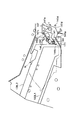
As shown in FIG. 39, an
ドラム枠体118には感光体ドラム107を保護するためのドラムシャッター170が取り付けられている。ドラムシャッター170は、感光体ドラム107を覆うシャッター部170aと、前記シャッター部170aの両端を支持する支持アーム170b(図示は一端部のみ)、及び、軸部170cを有する。そして、前記軸部170cを支点にして回動可能にドラム枠体118に取り付けられている。前記シャッター170は、カートリッジBを装置本体Aに装着する動作と連動して矢印s方向に回動する。そして、感光体ドラム107を保護する位置(図38)から感光体ドラム107が露出する位置(図39)に移動する。
A
また、図39に示すように、ドラム枠体118には前記第1、第2、第3のカートリッジ可動部材142、162、182が取り付けられている。そして、四節リンクを構成している。
Further, as shown in FIG. 39, the first, second and third cartridge
前記第1カートリッジ可動部材142は、軸118mに回動可能に取り付けられている。前記第2カートリッジ可動部材162は、実施例1〜実施例4で説明したカートリッジ可動部材142と同じ動きをする。前記第2カートリッジ可動部材162の穴部162aに、同軸線上に円柱を連ねた形状(段軸)の止め軸150を貫通させる。そして、止め軸150をドラム枠体118の止め穴118iに圧入する。これによって、前記第2カートリッジ可動部材162は、前記止め軸150を中心にして回動可能に支持されている。止め軸150は、第2カートリッジ可動部材162の脱落防止のため大径部150aを有する。第2カートリッジ可動部材162を組み込む際には、後述するフランジの偏心軸と係合する突き当て部162bが、ドラム枠体118の側面に設けられた開口部118hに入るように組み込む。
The first cartridge
第3カートリッジ可動部材182は、その両端部に設けた二つの穴が第1カートリッジ可動部材142の突軸142g及び第2カートリッジ可動部材162の突軸162gと回動可能に連結されている。これによって、四節リンクを構成している。
The third cartridge
四節リンクの動きは、第2カートリッジ可動部材162の回転によって規制する。即ち、その移動範囲は、第1カートリッジ可動部材142が矢印a(図41)の向きに移動する際には、第2カートリッジ可動部材162の突き当て部162bが突き当て部118eに突き当たるまで(図41の位置)である。また、第1カートリッジ可動部材142が矢印bの向きに移動する際には、第2カートリッジ可動部材162の突き当て部142bが突き当て部118fに突き当たるまで(図42の位置)である。前記四節リンクは、前述したように、可動範囲を規制されている。
The movement of the four-bar link is restricted by the rotation of the second cartridge
図39に示すように、第2カートリッジ可動部材162のバネかけ部162eに引っ張りコイルばね143の一端143aを取り付ける。また、前記ばね143の他端143bをドラム枠体118の側面の突軸118kに取り付ける。図39に示すように、前記ばね143をかけるバネかけ部142e及び突軸118kは、ばね143が外れるのを防止するためにばね143をかける部分の外側にばね143の外径より大きな大径部を有する。第2カートリッジ可動部材162が前記可動範囲内で動いた場合に、ばね143には常に圧縮する向きの力が発生するように、ばね143は十分延ばした状態で使用する。
As shown in FIG. 39, one
そして、第2カートリッジ可動部材162がトグルの釣り合いの位置(不図示)よりも図41に近い側に位置する場合には、ばね力により第1カートリッジ可動部材142を矢印a向きに付勢する。尚、図41に示すように、コイルばね143によって付勢された第2カートリッジ可動部材162は、突き当て部162bがドラム枠体118の突き当て部118eに突き当たることで回転方向の位置決めがされる。従って、第1カートリッジ可動部材142は、四節リンク機構の動きによりこれに対応する位置まで移動する。
When the second cartridge
また、第2カートリッジ可動部材162がトグルの釣り合いの位置よりも図42に近い側に位置する場合には、ばね力により第1カートリッジ可動部材142を矢印bの向きに付勢する。図42に示すように、コイルばね143によって付勢された第2カートリッジ可動部材162は、突き当て部162bがドラム枠体118の突き当て部118fに突き当たることで回転方向の位置決めがなされる。そして、第1カートリッジ可動部材142は、四節リンク機構によりこれに対応する位置まで移動する。
Further, when the second cartridge
実施例1で説明した図12に示す構成と同様の構成にて、感光体ドラム107の一端部にフランジ151が固着されている。前記フランジ151は、穴部151aと偏心軸151bを有している。そして、前記穴部151aを円筒部140L1の小径部で支持する。これによって、偏心軸151bが感光体ドラム107の回転とともに、小径部140L1aを中心にして回転する。これは、実施例1と同じである。
A
また、突き当て部162bは、開口部118hを貫通しさらに内側へと突出する。その突出量は、実施例1の図20に示すように、感光体ドラム107の中心軸方向において、前記偏心軸151bと重なる領域までである。
The abutting
上記のように構成すれば、実施例1と同様に、感光体ドラム107が回転すると偏心軸150bと第2カートリッジ可動部材162の突き当て部162bが係合して移動する。従って、第2カートリッジ可動部材162の移動とともに、第1カートリッジ可動部材142も図41の状態から図42の状態へと変化する。
If configured as described above, as in the first embodiment, when the
(2)装置本体Aに設けられた帯電電気接点
次に、カートリッジBを装着可能な装置本体Aについて説明する。
(2) Charging electrical contact provided in apparatus main body A Next, the apparatus main body A in which the cartridge B can be mounted will be described.
図43に示すように、装置本体Aの内装面には前記電気接点141aと接触して帯電バイアス電圧を帯電ローラ108に印加するための本体帯電接点部材144が設けられている。
As shown in FIG. 43, a main body charging
カートリッジBが装置本体Aに装着されていない状態では、前記接点部材144は装置本体Aの内装面に設けられたカバー171から突出しない位置に退避している(図43)。前記接点部材144は、リード線などで装置本体A内部に設けられた電源回路Eに接続している。
When the cartridge B is not attached to the apparatus main body A, the
また、実施例1と同様に、装置本体Aの内部には、前記固定部材146が内側板145から突出して設けられている。そして、カートリッジBの装着方向において、固定部材146より下流側には本体可動部材147の一端部147cが突出している。
Similarly to the first embodiment, the fixing
前記本体可動部材147は、軸部147aを中心に回動可能に取り付けられている。そして、前記本体可動部材147は、前記可動部材142の回転動作と連動して矢印c、d方向に移動する。装置本体AにカートリッジBを装着完了後、画像形成の準備ができた後に、感光ドラム107が回転する。すると、図44に示すように、前記本体可動部材147が前記可動部材142(図38、図39)によって矢印c方向に押される。これにより、本体可動部材147の動作と連動して帯電電気接点144aがカバー171から内側へ突出する。そして、電気接点144aが移動して、静止している電気接点141aと接触する。即ち、電気接続位置に静止して待機している前記接点141aに対して、前記接点144aが回動移動して接触する。そして、前記接点144aは、前記接点141aと接触した後、前記接点141aに対して摺動する。従って、両接点間に付着するゴミ、現像剤等を除去することができる。よって、両接点の電気的接続の信頼性を向上させることができた。
The main body
(3)可動部材と帯電接点部材の動作の説明
次に、第1カートリッジ可動部材142と本体帯電接点部材144の動作について説明する。図45は、カートリッジBを装置本体Aに装入するときの動作を説明するための模式図である。
(3) Description of Operation of Movable Member and Charging Contact Member Next, the operation of the first cartridge
図45は、装置本体Aに設けられた内側板145を装置本体内部から見た図(図43の矢印Y方向から見た図)である。そして、図45は、カートリッジBを装置本体Aに装入する途中の状態を示す図、図46は、カートリッジBが装置本体Aに装着された後に、接点141aと接点144aとが接触した状態を示す図である。
45 is a view of the
図45に示すように、本体可動部材147は、内側板145に軸部147aを中心として回動可能に取り付けられる。また、本体帯電接点部材144は、本体可動部材147に取り付けられている。本体可動部材147は、圧縮バネ(不図示)によって矢印d方向に付勢されている。これによって、本体可動部材147は、突き当て部147dが内側板145の突き当て部145dに当接して位置が決められる。この際、前記電気接点144aは、本体内装面のカバー171から装置本体A内部に突出しない位置に位置する。
As shown in FIG. 45, the main body
カートリッジBは、装着ガイド部130L1、130L2に沿って矢印X方向に装入される。 The cartridge B is loaded in the arrow X direction along the mounting guide portions 130L1 and 130L2.
図45に示す位置では、先に述べたように、第2カートリッジ可動部材162はコイルばね143の作用によって矢印jの方向に付勢されている。これによって、前記可動部材162は、突き当て部162bとドラム枠体118の突き当て部118eとが突き当たる位置に位置する。また、前記接点144aは、前述したように、カバー171から突出しない位置となっている。
In the position shown in FIG. 45, as described above, the second cartridge
そして、カートリッジBを装置本体Aに装着完了後に,カートリッジドア109(図3)を閉じる。これによって、画像形成装置100が画像形成の準備に入る。
Then, after the cartridge B is completely attached to the apparatus main body A, the cartridge door 109 (FIG. 3) is closed. As a result, the
装置本体Aが動作を開始し、駆動力が伝達されて感光体ドラム107が回転する。すると、先に説明した通り、前記第1カートリッジ可動部材142は、図41に示す位置から矢印kの向きに回転する。そして、前記可動部材142は、トグルの釣り合いの位置を通過して図42及び図46の位置まで回転する。
The apparatus main body A starts operating, the driving force is transmitted, and the
その際、先ず、第1カートリッジ可動部材142の係合部142dが本体可動部材147の一端147cに接触し始める。さらに前記可動部材142が矢印kの向きに回転する。すると、前記可動部材142の係合部142dが本体可動部材147を押す。従って、本体可動部材147が矢印c方向に回転する。これにより、前記電気接点144aがカバー171の奥に退避した状態(図45)から、カバー171の外側へと装置本体A内側に突出してくる。そして、前記可動部材142が図46の位置まで回転する間に、前記係合部142dがさらに本体可動部材147を矢印c方向に回転させる。そして、これと連動して、前記電気接点144aがさらにカバー171から突出する。これによって、前記電気接点144aが移動して、静止している前記電気接点141aと接触する。
At that time, first, the engaging
これにより装置本体Aから前記帯電ローラ108に帯電バイアスを印加可能となる。
As a result, a charging bias can be applied from the apparatus main body A to the charging
また、装置本体AからカートリッジBを取り出す際には、実施例1と同様に、前記可動部材142が前記固定部材146と係合する。これによって、前記可動部材142は回転して、前記可動部材142は再び図41に示す位置へ戻される。前記可動部材142の動きに連動して本体可動部材147が矢印dの向きに移動する。これによって、前記電気接点144aが本体内部に突出した状態から、再び退避した状態となる(図43及び図45)。
Further, when the cartridge B is taken out from the apparatus main body A, the
カートリッジBが装置本体Aの外に取り出された際には、前記電気接点141aは再びカートリッジ可動部材142で覆われ、保護された状態となっている。
When the cartridge B is taken out of the apparatus main body A, the
本実施例においても、前述した実施例1の効果と同様の効果を達成することができる。 Also in the present embodiment, the same effect as that of the first embodiment can be achieved.
また、本実施例によれば、ドラムシャッター170の回転軸方向において、支持アーム170bの通過経路よりも外側にカートリッジ可動部材142、162、182を設けた。これによって、カートリッジBの着脱時に、ドラムシャッター170とカートリッジ可動部材142、162、182の開閉タイミングを考慮しなくて良い。また、画像形成装置の小型化を図ることができる。
Further, according to the present embodiment, the cartridge
尚、前記実施例では、カートリッジ可動部材142を移動させるのに感光体ドラム107の回転を利用した。しかしながら、これに限定されるものではない。例えば現像ローラ110の回転を利用して同様に構成しても良い。
In the embodiment, the rotation of the
実施例6
次に、図47〜図53を参照して本発明の第六の実施例について説明する。
Example 6
Next, a sixth embodiment of the present invention will be described with reference to FIGS.
本実施例は、次に説明する構成を除いて、前述した実施例5と同様の構成である。、実施例5と異なるのは、前記電気接点141aを保護しているのがドラム枠体118に設けたリブ118gではなく、第1カートリッジ可動部材142である点である。
The present embodiment has the same configuration as that of the fifth embodiment described above except for the configuration described below. The difference from the fifth embodiment is that the
具体的には、前記接点141aを第1カートリッジ可動部材142の裏側に配置する。これによって、前記可動部材142で前記電気接点141aを覆う。その他の構成及び動作については前述の実施例5と同様の構成である。特に説明のない部分は実施例5と同じである。従って、本実施例では、前述した実施例5の構成と異なる構成部分について説明する。そして、実施例5と同様の構成、機能を有する部材については同一の参照番号を付して先の実施例の説明を援用する。
Specifically, the
図47〜図51は、本発明を適用したカートリッジBの実施例を示した図である。図47〜図51は、それぞれ、実施例5の図38〜図42に相当する。 47 to 51 are views showing an example of the cartridge B to which the present invention is applied. 47 to 51 correspond to FIGS. 38 to 42 of the fifth embodiment, respectively.
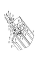
図47は、カートリッジBを装置本体Aに装着する前の第1、第2及び第3のカートリッジ可動部材142、162、182の構成を表わす斜視図である。図48は、前記可動部材142、162、182のドラム枠体118への取り付け方法を示す。そして、図49は、図47において第2、第3可動部材162、182がない状態の第1可動部材142及び前記接点部材141の近傍のみを表わした図である。
47 is a perspective view showing the configuration of the first, second, and third cartridge
図50は、カートリッジBを装置本体Aに装着する前の第1、第2及び第3の可動部材142、162、182の構成を表わす側面図である。そして、図51は、装着後、感光体ドラム107の回転により可動部材162が移動して、突き当て部118eに突き当たった後の状態を表わす側面図である。
50 is a side view showing the configuration of the first, second, and third
図52及び図53は、実施例5の図45及び図46の状態に相当する。図52は、装置本体Aの内側板145を装置本体内部から見た図(図43の矢印Y方向から見た図)である。また、図52は、カートリッジBを装置本体Bに装入する途中の状態を示す図である。図54は、カートリッジBを装置本体Aに装着した後に、第1カートリッジ可動部材142が移動して、電気接点144aが前記電気接点141aと接触した状態を示す図である。
52 and 53 correspond to the states of FIGS. 45 and 46 in the fifth embodiment. 52 is a view of the
(1)カートリッジ帯電接点部材及びカートリッジ可動部材
図48に示すように、カートリッジBの装着方向Xの前方であつて、長手方向端部近傍には、帯電ローラ108に帯電バイアス電圧を印加するための前記電気接点141aが配置されている。カートリッジ帯電接点部材141は、その角部近傍の領域が、前記電気接点144aと接触する電気接点141aとなっている。尚、図48は、実施例5の図39に相当する。
(1) Cartridge charging contact member and cartridge movable member As shown in FIG. 48, in front of the mounting direction X of the cartridge B and in the vicinity of the end in the longitudinal direction, a charging bias voltage is applied to the charging
図49に示すの状態においては、前記接点141aは、前記可動部材142から露出しないように、前記可動部材142の背面に配置している。そして、前記接点141aは、前記可動部材142によって保護された状態にある。尚、図49は、実施例5の図40の状態に相当する。
In the state shown in FIG. 49, the
(2)カートリッジ可動部材の動作の説明
前記カートリッジ可動部材142の「トグル」の動きは実施例5と同じである。感光体ドラム107の回転により、前記矢印bの向きに回転する(図51)。そして、可動部材142は、図50の位置からトグルの釣り合いの位置(不図示)を通過して図51の位置まで移動する。この際、前記可動部材142が矢印bの向きに回転するのに従って、前記電気接点141aが徐々に露出し、完全に露出した状態となる(図51)。尚、図50は図41に相当する。また、図51は図42に相当する。
(2) Description of Operation of Cartridge Moving Member The “toggle” movement of the
(3)装置本体Aに設けられた本体帯電接点部材
次に、装置本体Aに設けられる本体帯電接点部材144は、実施例5と同様の構成である。図43を用いて実施例5で既に説明した通りである。
(3) Main Body Charging Contact Member Provided in Apparatus Main Body A Next, the main
(4)可動部材と本体帯電接点部材の動作の説明
前記可動部材142の移動によって、前記接点144aが前記電気接点141aと接触する構成は実施例5と同じである。
(4) Description of Operation of Movable Member and Main Body Charging Contact Member The configuration in which the
カートリッジBを装置本体Aに装着する前カートリッジ装着途中(図52)、及び、装着直後においては、前記電気接点141aは、前記可動部材142によって覆われていて露出していない状態である。即ち、前記可動部材142によって保護された状態にある。
Before the cartridge B is attached to the apparatus main assembly A (FIG. 52) and immediately after the attachment, the
カートリッジBを装着完了後に、カートリッジドア109(図3)を閉じる。これによって、装置本体Aが画像形成の準備に入る。 After the cartridge B is completely installed, the cartridge door 109 (FIG. 3) is closed. As a result, the apparatus main body A is ready for image formation.
装置本体Aが動作を開始し、駆動力が伝達されて感光体ドラム107が回転する。すると、前記可動部材142が図52の位置から図51の位置へと向かって矢印bの向きに回転する。これによって、前記電気接点141aを徐々に露出させる。それと共に、前記可動部材142は、本体可動部材147と接触する。そして、実施例5で説明した機構により、前記本体帯電部材144を装置本体Aの内部に向かって動かす。そして、前記電気接点141aが完全に露出した後に、前記電気接点141aと前記電気接点144とが接触し始める。
The apparatus main body A starts operating, the driving force is transmitted, and the
最終的に、前記可動部材142は、図51及び図53に示す位置まで移動する。そして、前記接点141aと前記電気接点144aとが確実に接触した状態で停止する。即ち、静止している前記接点141aに対して、前記電気接点144aが移動して近ずき、両者は接触する。この状態で、前記可動部材142は停止する。
Finally, the
これにより装置本体Aから前記帯電ローラ108に帯電バイアスを印加可能となる。
As a result, a charging bias can be applied from the apparatus main body A to the charging
また、装置本体AからカートリッジBを取り出す際には、実施例5と同様の動作により、固定部材前記可動部材142は、再び図50及び図52の位置へ戻される。
When taking out the cartridge B from the apparatus main body A, the
また、装置本体AからカートリッジBを取り出す際も、実施例5と同様の動作により、固定部材前記可動部材142は、再び図50の位置へ戻される。前記可動部材142の動きに連動して、本体可動部材147が矢印dの向きに移動し(図43)、前記接点144aが本体内部に突出した状態から再び退避した状態となる(図43及び図52)。
Further, when the cartridge B is taken out from the apparatus main body A, the
カートリッジBが装置本体Aの外に取り出された際には、前記接点141aは、再び前記可動部材142で覆われ、保護された状態となる。
When the cartridge B is taken out of the apparatus main body A, the
本実施例においても、前述した実施例1、及び、実施例2の効果と同様の効果を達成することができる。 Also in the present embodiment, the same effects as those of the first embodiment and the second embodiment described above can be achieved.
また、実施例2と同様に、本実施例においても、前記支持アームの通過経路より外側にカートリッジ可動部材142、162、182を設けた。従って、プロセスカートリッジBの着脱時にドラムシャッター170とカートリッジ可動部材142、162、182の開閉タイミングを考慮しなくて良い。また、画像形成装置の小型化を図ることができる。
Similarly to the second embodiment, in this embodiment, the cartridge
なお、本実施例6では帯電接点を保護する構成とした。しかしながら、本発明は、これに限定されるものではない。例えば、同様の構成において、現像接点を保護しても良い。 In Example 6, the charging contact was protected. However, the present invention is not limited to this. For example, in the same configuration, the development contact may be protected.
尚、前述した各実施例では、可動部材142を回転させるにあたって、感光体ドラム107の回転力とばね143の弾性力を用いた。しかしながら、これに限定されるものではない。例えば、ばねの弾性力を用いずに、感光体ドラムの回転力のみによって可動部材を移動させても良い。或いは、感光体ドラムの代わりに、例えば現像ローラを用いても良い。
In each of the above-described embodiments, the rotational force of the
更に、本実施例6では帯電接点のみを保護する構成とした。しかしながら、これに限定されるものではない。例えば、実施例4で示したような現像接点を保護する構成を同時に採用しても良い。これにより両電気接点が保護される。 Further, in the sixth embodiment, only the charging contact is protected. However, the present invention is not limited to this. For example, a configuration for protecting the development contact as shown in the fourth embodiment may be employed at the same time. This protects both electrical contacts.
また、可動部材142は、電気接点141aを完全に覆っていなくても良い。例えば、可動部材142、或いは、突出部等を、電気接点表面よりも突出させる。または、可動部材142、或いは、突出部等により電気接点表面の一部を覆う。これらにより、同様の効果を得ることができる。この「覆う」の形態については、次の実施例7で幾つか例を挙げて説明する。
Further, the
実施例7
次に、図54〜図58を参照して本発明の第七の実施例について説明する。
Example 7
Next, a seventh embodiment of the present invention will be described with reference to FIGS.
本実施例では既に述べた実施例1〜6と異なる構成のみを説明し、実施例1〜6と同様の構成については説明を省略する。 In the present embodiment, only the configuration different from the first to sixth embodiments described above will be described, and the description of the same configuration as the first to sixth embodiments will be omitted.
図54〜図58は、それぞれ前記可動部材142の一実施形態を示したものである。各図において、前記可動部材142以外の部材は、省略されている。また、本実施例のカートリッジBには、前述した実施例5、及び、実施例6と同様に、前記接点141aが配置されている。前記接点部材141は、その角部近傍の領域が前記電気接点144aと接触する前記電気接点141aとなっている。また、前記可動部材142も前述の実施例5、及び、実施例6と同様に支持、位置決めされている。
54 to 58 show an embodiment of the
図54に示す実施形態は、待機状態において、前記可動部材142が前記接点141aの周囲を囲むようにしたものである。また、本実施形態は、前記接点141aの表面を、前記可動部材142が有する、複数のリブ142uを有する骨格構造で包囲している。
In the embodiment shown in FIG. 54, the
図55に示す実施形態は、前記可動部材142に、待機状態にて前記接点141aの上部の一部を覆うように、リブ142vを設けている。
In the embodiment shown in FIG. 55, the
図56、図57、図58に示す実施形態は、前記可動部材142に、待機状態にて前記接点141aの表面よりも高くなるように、突出部(面)142w、142x、142yを設けたものである。この突出部142w、142x、142yは、前記接点141aの周囲の一部に設けている。
In the embodiment shown in FIGS. 56, 57, and 58, the
つまり、図56に示す実施形態では、突出部142wは、図面上、前記接点141aの上側に位置するように、前記可動部材142に設けられている。図57に示す実施形態では、突出部142xは、図面上、前記接点141aに対面した側に位置するように、前記可動部材142に設けられている。図58に示す実施形態では、突出部142yは、図面上、前記接点141aの側面部に位置するように、前記可動部材142に設けられている。
That is, in the embodiment shown in FIG. 56, the projecting
本実施例によれば、いずれの実施形態のカートリッジ可動部材142においても、接点141aの近傍に接点141aよりも高い面に、リブ142u、リブ141v、或いは、突出部(面)142w、142x、142yを設けた。そのため、操作者がカートリッジを取り扱う際に、電気接点に不用意に触れることを抑止することができる。従って、いずれの実施例においても、前記電気接点141aを保護することができる。
According to the present example, in any of the cartridge
本実施例においても、上記実施例1〜実施例6と同様の効果を達成することができる。 Also in this embodiment, the same effects as those of the first to sixth embodiments can be achieved.
また、前述した各実施例で示したプロセスカートリッジは単色画像を形成する場合を例示した。しかしながら、本発明に係るプロセスカートリッジは現像手段を複数設け、複数色の画像(例えば2色画像、3色画像或いはフルカラー等)を形成するカートリッジにも好適に適用することができる。 Further, the process cartridge shown in each of the above-described embodiments is exemplified for forming a single color image. However, the process cartridge according to the present invention can be suitably applied to a cartridge that is provided with a plurality of developing means and forms a multi-color image (for example, a two-color image, a three-color image, or a full color).
また、電子写真感光体としては、前記感光体ドラムに限定されることなく、例えば次のものが含まれる。先ず感光体としては光導電体が用いられ、光導電体としては例えばアモルファスシリコン、アモルファスセレン、酸化亜鉛、酸化チタン及び有機光導電体(OPC)等が含まれる。また前記感光体を搭載する形状としては例えばドラム状またはベルト状のものが用いられている。例えばドラムタイプの感光体にあっては、アルミ合金等のシリンダ上に光導電体を蒸着或いは塗工を行ったものである。 Further, the electrophotographic photosensitive member is not limited to the photosensitive drum, and includes, for example, the following. First, a photoconductor is used as the photoreceptor, and examples of the photoconductor include amorphous silicon, amorphous selenium, zinc oxide, titanium oxide, and organic photoconductor (OPC). For example, a drum-like or belt-like shape is used for mounting the photoconductor. For example, in a drum type photoreceptor, a photoconductor is deposited or coated on a cylinder of aluminum alloy or the like.
また、現像方法としても、公知の2成分磁気ブラシ現像法、カスケード現像法、タッチダウン現像法、クラウド現像法等の種々の現像法を用いることが可能である。 As the developing method, various developing methods such as a known two-component magnetic brush developing method, cascade developing method, touch-down developing method, and cloud developing method can be used.
また、帯電手段の構成も、前述した実施の形態では所謂接触帯電方法を用いた。しかしながら、他の構成として従来から用いられているタングスワイヤーの三方周囲にアルミ等の金属シールドを施す。そして、前記タングスワイヤーに高電圧を印加することによって生じた正または負のイオンを感光体ドラムの表面に移動させ、該ドラムの表面を一様に帯電する構成を用いても良い。 In addition, as the configuration of the charging means, the so-called contact charging method is used in the above-described embodiment. However, a metal shield such as aluminum is provided around three sides of the tongue wire conventionally used as another configuration. A configuration may be used in which positive or negative ions generated by applying a high voltage to the tongue wire are moved to the surface of the photosensitive drum, and the surface of the drum is uniformly charged.
なお、前記帯電手段としては前記ローラ型以外にも、ブレード(帯電ブレード)、パッド型、ブロック型、ロッド型、ワイヤ型等のものでも良い。 In addition to the roller type, the charging means may be a blade (charging blade), pad type, block type, rod type, wire type, or the like.
また感光体ドラムに残存するトナーのクリーニング方法としても、ブレード、ファーブラシ、磁気ブラシなど用いてクリーニング手段を構成しても良い。 Further, as a method for cleaning the toner remaining on the photosensitive drum, the cleaning unit may be configured using a blade, a fur brush, a magnetic brush, or the like.
本発明は、プロセスカートリッジを電子写真画像形成装置本体に装着した際に、前記プロセスカートリッジの有する入力電気接点と、前記画像形成装置本体に設けられた出力電気接点との電気接続の信頼性を向上させることができる。また、電子写真画像形成装置本体に設けられた電気回路が損傷することを防止できる。 The present invention improves the reliability of electrical connection between an input electrical contact of the process cartridge and an output electrical contact provided in the image forming apparatus body when the process cartridge is mounted on the electrophotographic image forming apparatus body. Can be made. Further, it is possible to prevent the electric circuit provided in the electrophotographic image forming apparatus main body from being damaged.
A 電子写真画像形成装置本体
B プロセスカートリッジ
107 感光体ドラム(電子写真感光体)
108 帯電ローラ(帯電部材)
109 カートリッジドア
110 現像ローラ(現像部材)
130a カートリッジ装着部
134 カップリング
141 カートリッジ帯電接点部材、現像接点部材(入力電気接点部材)
141a、b 接点(入力電気接点)
142、162、182 カートリッジ可動部材(可動作動部材)
142d 第2係合部
142f 第1係合部
143 ねじりコイルばね(弾性作用部材)
144 本体帯電接点部材、本体現像接点部材(出力電気接点部材)
144a 接点(出力電気接点)
145 装置本体内側板
146 固定部材
146a 当接部
147 本体可動部材(可変位部材)
147c 可変位係合部
148 接点支持部材
149 圧縮ばね(弾性機能部材)
A Electrophotographic image forming apparatus main body
108 Charging roller (charging member)
109
130a
141a, b contact (input electrical contact)
142, 162, 182 Cartridge movable member (movable operating member)
142d Second engagement portion 142f
144 Main unit charging contact member, Main unit developing contact member (Output electric contact member)
144a Contact (output electrical contact)
145 Device main body
147c Variable
Claims (11)
電子写真感光体ドラムと、
前記電子写真感光体ドラムに作用するプロセス手段と、
カートリッジ枠体に対して相対的に移動可能に設けられた可動作動部材であって、前記プロセスカートリッジが前記電子写真画像形成装置本体に装着された後に、前記電子写真画像形成装置本体から前記プロセスカートリッジに駆動力が伝達されることによって変位し、それにより前記電子写真画像形成装置本体に設けられている前記可変位部材と係合して前記可変位部材を移動させ、前記可変位部材の動きに連動して前記出力電気接点を前記退避位置から前記電気接続位置に、前記弾性機能部材の弾性力に抗して、移動させる可動作動部材と、
前記電気接続位置に位置せしめられた出力電気接点に係合し、前記プロセス手段が機能するための電圧を受ける入力電気接点と、
を有することを特徴とするプロセスカートリッジ。 A cartridge mounting portion on which a process cartridge is detachably mounted, an inner plate, an electric connection position protruding from the inner plate to the side where the cartridge mounting portion is provided, and the inner plate retracted from the electric connection position An output electrical contact that can move between a retracted position that does not protrude from the side where the cartridge mounting portion is provided, a variable position member that moves the output electrical contact, and the output electrical contact retracted from the electrical connection position A process cartridge that is detachably mounted on the electrophotographic image forming apparatus main body having an elastic functional member that elastically biases the variable position member so as to move to a position,
An electrophotographic photosensitive drum;
Process means acting on the electrophotographic photosensitive drum;
A movable actuating member provided so as to be movable relative to a cartridge frame, wherein after the process cartridge is mounted on the electrophotographic image forming apparatus main body, the process cartridge is moved from the electrophotographic image forming apparatus main body. Is displaced by the transmission of the driving force, thereby engaging with the variable position member provided in the main body of the electrophotographic image forming apparatus to move the variable position member, and to move the variable position member. A movable actuating member that moves the output electrical contact from the retracted position to the electrical connection position in opposition to the elastic force of the elastic function member;
An input electrical contact that engages an output electrical contact positioned at the electrical connection location and receives a voltage for the process means to function;
A process cartridge comprising:
前記電子写真画像形成装置本体が、
内側板と、
電源と、
前記電源と接続された電源回路と、
前記プロセスカートリッジが取り外し可能に装着されるカートリッジ装着部と、
固定して設けられた固定部材と、
前記内側板から前記カートリッジ装着部の設けられた側に突出している電気接続位置と、前記電気接続位置から退避した、前記内側板から前記カートリッジ装着部の設けられた側に突出していない退避位置との間を移動可能に設けられ、前記電源と前記電源回路を介して電気的に連結された出力電気接点と、
可変位係合部を有しており、前記出力電気接点を移動させる可変位部材であって、前記プロセスカートリッジが前記電子写真画像形成装置本体に挿入される挿入方向において、前記可変位係合部が前記固定部材よりも下流側に設けられている、かつ、前記挿入方向において、少なくとも前記可変位係合部の一部が固定部材と重なっている可変位部材と、
前記出力電気接点を前記電気接続位置から前記退避位置に移動させるように前記可変位部材を弾性的に付勢する弾性機能部材と、を有し、
前記プロセスカートリッジが、
電子写真感光体ドラムと、
前記電子写真感光体ドラムに作用するプロセス手段と、
カートリッジ枠体に対して相対的に移動可能に設けられた可動作動部材であって、前記プロセスカートリッジが前記固定部材を通過して前記カートリッジ装着部に装着された後に、前記電子写真画像形成装置本体から前記プロセスカートリッジに駆動力が伝達されることによって変位し、それにより前記電子写真画像形成装置本体に設けられている前記可変位部材と係合して前記可変位部材を移動させ、前記可変位部材の動きに連動して前記出力電気接点を前記退避位置から前記電気接続位置に、前記弾性機能部材の弾性力に抗して移動させる可動作動部材と、
前記電気接続位置に位置せしめられた出力電気接点に係合し、前記プロセス手段が機能するための電圧を受ける入力電気接点と、
を有することを特徴とするプロセスカートリッジ。 In the process cartridge that is detachably mounted on the electrophotographic image forming apparatus main body,
The electrophotographic image forming apparatus main body is
An inner plate,
Power supply,
A power supply circuit connected to the power supply;
A cartridge mounting portion on which the process cartridge is detachably mounted;
A fixed member provided fixedly;
An electrical connection position that protrudes from the inner plate to the side where the cartridge mounting portion is provided, and a retracted position that is retracted from the electrical connection position and does not protrude from the inner plate to the side where the cartridge mounting portion is provided. An output electrical contact provided movably between the power source and electrically connected via the power source circuit;
A variable position member having a variable position engaging portion and moving the output electrical contact in the insertion direction in which the process cartridge is inserted into the electrophotographic image forming apparatus main body. Is provided downstream of the fixed member, and in the insertion direction, at least a part of the variable position engaging portion overlaps the fixed member,
An elastic functional member that elastically biases the variable position member so as to move the output electrical contact from the electrical connection position to the retracted position;
The process cartridge is
An electrophotographic photosensitive drum;
Process means acting on the electrophotographic photosensitive drum;
A movable operation member provided to be movable relative to a cartridge frame, wherein the process cartridge passes through the fixed member and is mounted on the cartridge mounting portion, and then the electrophotographic image forming apparatus main body Is displaced by transmitting a driving force to the process cartridge, thereby engaging the variable position member provided in the electrophotographic image forming apparatus main body to move the variable position member, and A movable actuating member that moves the output electrical contact from the retracted position to the electrical connection position against the elastic force of the elastic functional member in conjunction with the movement of the member;
An input electrical contact that engages an output electrical contact positioned at the electrical connection location and receives a voltage for the process means to function;
A process cartridge comprising:
(i)前記プロセスカートリッジが取り外し可能に装着されるカートリッジ装着部と、
(ii)内側板と、
(iii)前記内側板から前記カートリッジ装着部の設けられた側に突出している電気接続位置と、前記電気接続位置から退避した、前記内側板から前記カートリッジ装着部の設けられた側に突出していない退避位置との間を移動可能に設けられた出力電気接点と、
(iv)前記出力電気接点を移動させる可変位部材と、
(v)電子写真感光体ドラムと、
前記電子写真感光体ドラムに作用するプロセス手段と、
カートリッジ可動作動部材であって、前記プロセスカートリッジが前記電子写真画像形成装置本体に装着された後に前記電子写真画像形成装置本体から前記プロセスカートリッジに駆動力が伝達されることによって変位し、それにより前記電子写真画像形成装置本体に設けられている前記可変位部材と係合して前記可変位部材を移動させ前記可変位部材の動きに連動して前記出力電気接点を前記退避位置から前記電気接続位置に移動させる可動作動部材と、
前記プロセスカートリッジが前記画像形成装置本体に装着された際に、前記電気接続位置に位置する前記出力電気接点から前記電圧印加部材に給電するための印加バイアスを受ける入力電気接点と、
を有して、前記カートリッジ装着部に取り外し可能に装着されたプロセスカートリッジと、
を有することを特徴とする電子写真画像形成装置。 Ru is removably mounted to the process cartridge, electrophotographic image forming apparatus for forming an image on a recording medium,
(I) a cartridge mounting portion on which the process cartridge is detachably mounted;
(Ii) an inner plate;
(Iii) The electric connection position protruding from the inner plate to the side where the cartridge mounting portion is provided, and the electric connection position retracted from the electric connection position and not protruding from the inner plate to the side where the cartridge mounting portion is provided An output electrical contact provided so as to be movable between the retracted position;
(Iv) the displaceable member Before moving the output contact,
( V ) an electrophotographic photosensitive drum;
Process means acting on the electrophotographic photosensitive drum;
A cartridge movable operating member that is displaced by a driving force transmitted from the electrophotographic image forming apparatus main body to the process cartridge after the process cartridge is mounted on the electrophotographic image forming apparatus main body; Engaging with the variable position member provided in the electrophotographic image forming apparatus main body, the variable position member is moved , and the output electrical contact is moved from the retracted position to the electrical connection position in conjunction with the movement of the variable position member. a movable operation member Before moving on,
When said process cartridge is mounted to the image forming apparatus main body, and the input electrical contact of Ru receiving an applied bias to power the voltage application member from said output contact is located in the electrical connecting position,
And have a, a process cartridge mounted detachably to the cartridge mounting portion,
An electrophotographic image forming apparatus comprising:
(i)前記プロセスカートリッジが取り外し可能に装着されるカートリッジ装着部と、
(ii)内側板と、
(iii)電源と、
(iv)前記電源と接続された電源回路と、
(v)固定して設けられた固定部材と、
(vi)前記内側板から前記カートリッジ装着部の設けられた側に突出している電気接続位置と、前記電気接続位置から退避した、前記内側板から前記カートリッジ装着部の設けられた側に突出していない退避位置との間を移動可能に設けられ、前記電源と前記電源回路を介して電気的に連結された出力電気接点と、
(vii)可変位係合部を有しており、前記出力電気接点を移動させる可変位部材であって、前記プロセスカートリッジが前記カートリッジ装着部に装着される装着方向において、前記可変位係合部が前記固定部材よりも下流側に設けられている、かつ、前記挿入方向において、少なくとも前記可変位係合部の一部が固定部材と重なっている可変位部材と、
(viii)前記出力電気接点を前記電気接続位置から前記退避位置に移動させるように前記可変位部材を弾性的に付勢する弾性機能部材と、
(ix)電子写真感光体ドラムと、
前記電子写真感光体ドラムに作用するプロセス手段と、
カートリッジ枠体に対して相対的に移動可能に設けられた可動作動部材であって、前記プロセスカートリッジが前記固定部材を通過して前記カートリッジ装着部に装着された後に、前記電子写真画像形成装置本体から前記プロセスカートリッジに駆動力が伝達されることによって変位し、それにより前記電子写真画像形成装置本体に設けられている前記可変位部材と係合して前記可変位部材を移動させ、前記可変位部材の動きに連動して前記出力電気接点を前記退避位置から前記電気接続位置に、前記弾性機能部材の弾性力に抗して移動させる可動作動部材と、
前記電気接続位置に位置せしめられた出力電気接点に係合し、前記プロセス手段が作動するための電圧を受ける入力電気接点と、
を有して、前記カートリッジ装着部に取り外し可能に装着されたプロセスカートリッジと、
を有することを特徴とする電子写真画像形成装置。 Ru is removably mounted to the process cartridge, electrophotographic image forming apparatus for forming an image on a recording medium,
(I) a cartridge mounting portion on which the process cartridge is detachably mounted;
(Ii) an inner plate;
( Iii ) power supply,
( Iv ) a power supply circuit connected to the power supply;
( V ) a fixed fixing member;
(Vi) an electrical connecting position from the inner plate protrudes to the side provided with the said cartridge mounting portion, said retracted from the electrical connecting position, not protrude to the side provided with the said cartridge mounting portion from the inner plate no retraction position movably provided between the output contact that is electrically connected via the said power supply circuit,
( Vii ) a variable position member that has a variable position engaging portion and moves the output electrical contact, wherein the variable position engaging portion in the mounting direction in which the process cartridge is mounted to the cartridge mounting section; Is provided downstream of the fixed member, and in the insertion direction, at least a part of the variable position engaging portion overlaps the fixed member,
( Viii ) an elastic functional member that elastically biases the variable position member so as to move the output electrical contact from the electrical connection position to the retracted position;
( Ix ) an electrophotographic photosensitive drum;
Process means acting on the electrophotographic photosensitive drum;
A movable operation member provided to be movable relative to a cartridge frame, wherein the process cartridge passes through the fixed member and is mounted on the cartridge mounting portion, and then the electrophotographic image forming apparatus main body Is displaced by transmitting a driving force to the process cartridge, thereby engaging the variable position member provided in the electrophotographic image forming apparatus main body to move the variable position member, and A movable actuating member that moves the output electrical contact from the retracted position to the electrical connection position against the elastic force of the elastic functional member in conjunction with the movement of the member;
An input electrical contact that engages an output electrical contact positioned at the electrical connection location and receives a voltage for operating the process means;
And have a, a profile Seth cartridge mounted detachably to the cartridge mounting portion,
An electrophotographic image forming apparatus comprising:
Priority Applications (7)
| Application Number | Priority Date | Filing Date | Title |
|---|---|---|---|
| JP2004352495A JP4387933B2 (en) | 2003-12-09 | 2004-12-06 | Process cartridge and electrophotographic image forming apparatus |
| KR1020067011228A KR100827035B1 (en) | 2003-12-09 | 2004-12-08 | Process cartridge and electrophotographic image forming apparatus |
| CNB2004800364445A CN100511031C (en) | 2003-12-09 | 2004-12-08 | Process cartridge and electrophotographic image forming apparatus |
| PCT/JP2004/018669 WO2005057295A1 (en) | 2003-12-09 | 2004-12-08 | Process cartridge and electrophotographic image forming apparatus |
| TW093138143A TWI256529B (en) | 2003-12-09 | 2004-12-09 | Process cartridge and electrophotographic image forming apparatus |
| EP20040029156 EP1542095A1 (en) | 2003-12-09 | 2004-12-09 | Process cartridge and electrophotographic image forming apparatus |
| US11/007,464 US7228086B2 (en) | 2003-12-09 | 2004-12-09 | Electrophotographic image forming apparatus having process cartridge with electrical contacts |
Applications Claiming Priority (2)
| Application Number | Priority Date | Filing Date | Title |
|---|---|---|---|
| JP2003411063 | 2003-12-09 | ||
| JP2004352495A JP4387933B2 (en) | 2003-12-09 | 2004-12-06 | Process cartridge and electrophotographic image forming apparatus |
Publications (3)
| Publication Number | Publication Date |
|---|---|
| JP2005196145A JP2005196145A (en) | 2005-07-21 |
| JP2005196145A5 JP2005196145A5 (en) | 2007-08-16 |
| JP4387933B2 true JP4387933B2 (en) | 2009-12-24 |
Family
ID=34525497
Family Applications (1)
| Application Number | Title | Priority Date | Filing Date |
|---|---|---|---|
| JP2004352495A Expired - Fee Related JP4387933B2 (en) | 2003-12-09 | 2004-12-06 | Process cartridge and electrophotographic image forming apparatus |
Country Status (7)
| Country | Link |
|---|---|
| US (1) | US7228086B2 (en) |
| EP (1) | EP1542095A1 (en) |
| JP (1) | JP4387933B2 (en) |
| KR (1) | KR100827035B1 (en) |
| CN (1) | CN100511031C (en) |
| TW (1) | TWI256529B (en) |
| WO (1) | WO2005057295A1 (en) |
Families Citing this family (15)
| Publication number | Priority date | Publication date | Assignee | Title |
|---|---|---|---|---|
| JP4387933B2 (en) | 2003-12-09 | 2009-12-24 | キヤノン株式会社 | Process cartridge and electrophotographic image forming apparatus |
| JP4387932B2 (en) * | 2003-12-09 | 2009-12-24 | キヤノン株式会社 | Process cartridge and electrophotographic image forming apparatus |
| JP4345731B2 (en) * | 2005-09-15 | 2009-10-14 | ブラザー工業株式会社 | Developing cartridge, process cartridge, and image forming apparatus |
| JP4280770B2 (en) | 2006-01-11 | 2009-06-17 | キヤノン株式会社 | Process cartridge and electrophotographic image forming apparatus |
| JP6175862B2 (en) * | 2013-03-29 | 2017-08-09 | ブラザー工業株式会社 | Image forming apparatus |
| CN104090471B (en) * | 2014-07-21 | 2017-09-12 | 珠海天威飞马打印耗材有限公司 | Laser printer |
| KR102357024B1 (en) | 2014-11-28 | 2022-02-08 | 캐논 가부시끼가이샤 | Cartridge, member configuring cartridge and image formation device |
| SG11201901182YA (en) | 2016-08-26 | 2019-03-28 | Canon Kk | Drum unit, cartridge, electrophotographic image forming apparatus and coupling member |
| CN108398870A (en) * | 2017-02-07 | 2018-08-14 | 纳思达股份有限公司 | Handle box and electronic imaging apparatus |
| JP7062875B2 (en) * | 2017-03-07 | 2022-05-09 | ブラザー工業株式会社 | Drum cartridges and process cartridges |
| US9989917B1 (en) * | 2017-05-17 | 2018-06-05 | Lexmark International, Inc. | Toner cartridge with positional control features |
| JP7027138B2 (en) * | 2017-11-30 | 2022-03-01 | キヤノン株式会社 | Image forming device and cartridge that can be attached to the image forming device |
| JP7058992B2 (en) * | 2017-12-13 | 2022-04-25 | キヤノン株式会社 | Image forming equipment and cartridge |
| CN108121187A (en) * | 2018-01-26 | 2018-06-05 | 珠海天威飞马打印耗材有限公司 | Handle box and electrophotographic image forming |
| JP2022165266A (en) * | 2021-04-19 | 2022-10-31 | 株式会社リコー | image forming device |
Family Cites Families (33)
| Publication number | Priority date | Publication date | Assignee | Title |
|---|---|---|---|---|
| JPS62215278A (en) | 1986-03-15 | 1987-09-21 | Kyocera Corp | Electrophotographic device |
| JPH06317960A (en) | 1993-04-28 | 1994-11-15 | Canon Inc | Image forming device |
| JPH06313996A (en) | 1993-04-28 | 1994-11-08 | Canon Inc | Process cartridge, image forming device, method for assembling process cartridge and developing device |
| JP3236124B2 (en) | 1993-04-28 | 2001-12-10 | キヤノン株式会社 | Process cartridge, image forming apparatus, and method of attaching toner tape to process cartridge |
| JPH06317953A (en) | 1993-04-28 | 1994-11-15 | Canon Inc | Frame structure and image forming device |
| JPH06314001A (en) | 1993-04-28 | 1994-11-08 | Canon Inc | Gear unit and image forming device |
| JP3285417B2 (en) | 1993-04-28 | 2002-05-27 | キヤノン株式会社 | Process cartridge, image forming apparatus, and image forming system |
| JP3285413B2 (en) | 1993-04-28 | 2002-05-27 | キヤノン株式会社 | Photosensitive drum, process cartridge, and image forming apparatus |
| JP3320144B2 (en) | 1993-04-28 | 2002-09-03 | キヤノン株式会社 | Process cartridge, image forming apparatus, and image forming system |
| JPH06317954A (en) | 1993-04-28 | 1994-11-15 | Canon Inc | Method for assembling image forming device, image forming device and method for fitting armor cover |
| JP3285414B2 (en) | 1993-04-28 | 2002-05-27 | キヤノン株式会社 | Process cartridge and image forming apparatus |
| JP3347476B2 (en) | 1993-06-30 | 2002-11-20 | キヤノン株式会社 | Process cartridge regeneration method |
| JPH0777921A (en) | 1993-09-09 | 1995-03-20 | Fuji Xerox Co Ltd | Process cartridge mounting device for image forming device |
| JP3382399B2 (en) | 1994-12-26 | 2003-03-04 | キヤノン株式会社 | Process cartridge and image forming apparatus |
| JP3323696B2 (en) | 1995-06-13 | 2002-09-09 | キヤノン株式会社 | Ground member, electrophotographic photosensitive drum, process cartridge, and electrophotographic image forming apparatus |
| JPH0968833A (en) | 1995-09-04 | 1997-03-11 | Canon Inc | Electrophotographic image forming device |
| JP3352328B2 (en) | 1996-06-17 | 2002-12-03 | キヤノン株式会社 | Process cartridge and electrophotographic image forming apparatus |
| JP3290597B2 (en) * | 1996-08-30 | 2002-06-10 | キヤノン株式会社 | Process cartridge and electrophotographic image forming apparatus |
| JPH10228223A (en) * | 1997-02-14 | 1998-08-25 | Canon Inc | Process cartridge and electrophotographic image forming device |
| JPH10228224A (en) * | 1997-02-14 | 1998-08-25 | Canon Inc | Process cartridge and electrophotographic image forming device |
| JPH11231758A (en) | 1997-11-17 | 1999-08-27 | Canon Inc | Shutter and process cartridge |
| US6311026B1 (en) | 1998-11-13 | 2001-10-30 | Canon Kabushiki Kaisha | Process cartridge and image forming apparatus including means for detecting mounting of the process cartridge to main body of image forming apparatus, and process cartridge and developer cartridge including positioning portion |
| KR100413440B1 (en) * | 2001-06-09 | 2003-12-31 | 엘지전자 주식회사 | Pulsator type washing machine having drying function |
| JP3774691B2 (en) * | 2001-10-01 | 2006-05-17 | キヤノン株式会社 | Electrophotographic image forming apparatus |
| DE60228673D1 (en) * | 2001-12-28 | 2008-10-16 | Canon Kk | Process cartridge and electrophotographic image forming apparatus |
| JP3658381B2 (en) | 2002-06-04 | 2005-06-08 | キヤノン株式会社 | Electrophotographic image forming apparatus and process cartridge |
| JP2004125954A (en) | 2002-09-30 | 2004-04-22 | Canon Inc | Process cartridge, image forming apparatus and process cartridge attachment system |
| JP3625470B1 (en) * | 2003-09-30 | 2005-03-02 | キヤノン株式会社 | Process cartridge and electrophotographic image forming apparatus |
| JP4387933B2 (en) | 2003-12-09 | 2009-12-24 | キヤノン株式会社 | Process cartridge and electrophotographic image forming apparatus |
| JP4387934B2 (en) * | 2003-12-09 | 2009-12-24 | キヤノン株式会社 | Process cartridge and electrophotographic image forming apparatus |
| JP4387932B2 (en) | 2003-12-09 | 2009-12-24 | キヤノン株式会社 | Process cartridge and electrophotographic image forming apparatus |
| JP4095589B2 (en) | 2004-02-27 | 2008-06-04 | キヤノン株式会社 | Electrophotographic image forming apparatus and process cartridge |
| JP4035516B2 (en) | 2004-02-27 | 2008-01-23 | キヤノン株式会社 | Electrophotographic image forming apparatus |
-
2004
- 2004-12-06 JP JP2004352495A patent/JP4387933B2/en not_active Expired - Fee Related
- 2004-12-08 KR KR1020067011228A patent/KR100827035B1/en not_active IP Right Cessation
- 2004-12-08 WO PCT/JP2004/018669 patent/WO2005057295A1/en active Application Filing
- 2004-12-08 CN CNB2004800364445A patent/CN100511031C/en not_active Expired - Fee Related
- 2004-12-09 TW TW093138143A patent/TWI256529B/en not_active IP Right Cessation
- 2004-12-09 US US11/007,464 patent/US7228086B2/en not_active Expired - Fee Related
- 2004-12-09 EP EP20040029156 patent/EP1542095A1/en not_active Withdrawn
Also Published As
| Publication number | Publication date |
|---|---|
| EP1542095A1 (en) | 2005-06-15 |
| US20050135831A1 (en) | 2005-06-23 |
| JP2005196145A (en) | 2005-07-21 |
| WO2005057295A1 (en) | 2005-06-23 |
| US7228086B2 (en) | 2007-06-05 |
| CN100511031C (en) | 2009-07-08 |
| CN1890612A (en) | 2007-01-03 |
| KR100827035B1 (en) | 2008-05-06 |
| TWI256529B (en) | 2006-06-11 |
| TW200523692A (en) | 2005-07-16 |
| KR20060107549A (en) | 2006-10-13 |
Similar Documents
| Publication | Publication Date | Title |
|---|---|---|
| JP4387932B2 (en) | Process cartridge and electrophotographic image forming apparatus | |
| JP3625470B1 (en) | Process cartridge and electrophotographic image forming apparatus | |
| JP4387933B2 (en) | Process cartridge and electrophotographic image forming apparatus | |
| JP4194298B2 (en) | Information storage medium, unit, process cartridge, developing cartridge, and electrophotographic image forming apparatus | |
| US7215901B2 (en) | Process cartridge and electrophotographic image forming apparatus | |
| US7006776B2 (en) | Electrophotographic image forming apparatus having opening and closing member for opening and closing an opening through which a process cartridge is mounted | |
| US20100315658A1 (en) | Image forming apparatus | |
| JP2000155466A (en) | Magnetic seal member, developing device, process cartridge and electrophotographic image forming device | |
| JP2006267320A (en) | Image forming apparatus |
Legal Events
| Date | Code | Title | Description |
|---|---|---|---|
| A521 | Request for written amendment filed |
Free format text: JAPANESE INTERMEDIATE CODE: A523 Effective date: 20070629 |
|
| A621 | Written request for application examination |
Free format text: JAPANESE INTERMEDIATE CODE: A621 Effective date: 20070629 |
|
| A131 | Notification of reasons for refusal |
Free format text: JAPANESE INTERMEDIATE CODE: A131 Effective date: 20090616 |
|
| A521 | Request for written amendment filed |
Free format text: JAPANESE INTERMEDIATE CODE: A523 Effective date: 20090724 |
|
| TRDD | Decision of grant or rejection written | ||
| A01 | Written decision to grant a patent or to grant a registration (utility model) |
Free format text: JAPANESE INTERMEDIATE CODE: A01 Effective date: 20090929 |
|
| A01 | Written decision to grant a patent or to grant a registration (utility model) |
Free format text: JAPANESE INTERMEDIATE CODE: A01 |
|
| A61 | First payment of annual fees (during grant procedure) |
Free format text: JAPANESE INTERMEDIATE CODE: A61 Effective date: 20091001 |
|
| R150 | Certificate of patent or registration of utility model |
Free format text: JAPANESE INTERMEDIATE CODE: R150 |
|
| FPAY | Renewal fee payment (event date is renewal date of database) |
Free format text: PAYMENT UNTIL: 20121009 Year of fee payment: 3 |
|
| FPAY | Renewal fee payment (event date is renewal date of database) |
Free format text: PAYMENT UNTIL: 20131009 Year of fee payment: 4 |
|
| LAPS | Cancellation because of no payment of annual fees |