EP3543758B1 - Optische projektionssystemeinheit, optisches projektionssystem und optische projektionsvorrichtung - Google Patents
Optische projektionssystemeinheit, optisches projektionssystem und optische projektionsvorrichtung Download PDFInfo
- Publication number
- EP3543758B1 EP3543758B1 EP19161381.9A EP19161381A EP3543758B1 EP 3543758 B1 EP3543758 B1 EP 3543758B1 EP 19161381 A EP19161381 A EP 19161381A EP 3543758 B1 EP3543758 B1 EP 3543758B1
- Authority
- EP
- European Patent Office
- Prior art keywords
- optical system
- projection optical
- image display
- display surface
- projection
- Prior art date
- Legal status (The legal status is an assumption and is not a legal conclusion. Google has not performed a legal analysis and makes no representation as to the accuracy of the status listed.)
- Active
Links
Images



Classifications
-
- G—PHYSICS
- G02—OPTICS
- G02B—OPTICAL ELEMENTS, SYSTEMS OR APPARATUS
- G02B13/00—Optical objectives specially designed for the purposes specified below
- G02B13/16—Optical objectives specially designed for the purposes specified below for use in conjunction with image converters or intensifiers, or for use with projectors, e.g. objectives for projection TV
-
- G—PHYSICS
- G02—OPTICS
- G02B—OPTICAL ELEMENTS, SYSTEMS OR APPARATUS
- G02B26/00—Optical devices or arrangements for the control of light using movable or deformable optical elements
- G02B26/08—Optical devices or arrangements for the control of light using movable or deformable optical elements for controlling the direction of light
- G02B26/0816—Optical devices or arrangements for the control of light using movable or deformable optical elements for controlling the direction of light by means of one or more reflecting elements
- G02B26/0833—Optical devices or arrangements for the control of light using movable or deformable optical elements for controlling the direction of light by means of one or more reflecting elements the reflecting element being a micromechanical device, e.g. a MEMS mirror, DMD
-
- G—PHYSICS
- G03—PHOTOGRAPHY; CINEMATOGRAPHY; ANALOGOUS TECHNIQUES USING WAVES OTHER THAN OPTICAL WAVES; ELECTROGRAPHY; HOLOGRAPHY
- G03B—APPARATUS OR ARRANGEMENTS FOR TAKING PHOTOGRAPHS OR FOR PROJECTING OR VIEWING THEM; APPARATUS OR ARRANGEMENTS EMPLOYING ANALOGOUS TECHNIQUES USING WAVES OTHER THAN OPTICAL WAVES; ACCESSORIES THEREFOR
- G03B21/00—Projectors or projection-type viewers; Accessories therefor
- G03B21/005—Projectors using an electronic spatial light modulator but not peculiar thereto
- G03B21/008—Projectors using an electronic spatial light modulator but not peculiar thereto using micromirror devices
-
- G—PHYSICS
- G03—PHOTOGRAPHY; CINEMATOGRAPHY; ANALOGOUS TECHNIQUES USING WAVES OTHER THAN OPTICAL WAVES; ELECTROGRAPHY; HOLOGRAPHY
- G03B—APPARATUS OR ARRANGEMENTS FOR TAKING PHOTOGRAPHS OR FOR PROJECTING OR VIEWING THEM; APPARATUS OR ARRANGEMENTS EMPLOYING ANALOGOUS TECHNIQUES USING WAVES OTHER THAN OPTICAL WAVES; ACCESSORIES THEREFOR
- G03B21/00—Projectors or projection-type viewers; Accessories therefor
- G03B21/14—Details
- G03B21/142—Adjusting of projection optics
-
- G—PHYSICS
- G03—PHOTOGRAPHY; CINEMATOGRAPHY; ANALOGOUS TECHNIQUES USING WAVES OTHER THAN OPTICAL WAVES; ELECTROGRAPHY; HOLOGRAPHY
- G03B—APPARATUS OR ARRANGEMENTS FOR TAKING PHOTOGRAPHS OR FOR PROJECTING OR VIEWING THEM; APPARATUS OR ARRANGEMENTS EMPLOYING ANALOGOUS TECHNIQUES USING WAVES OTHER THAN OPTICAL WAVES; ACCESSORIES THEREFOR
- G03B21/00—Projectors or projection-type viewers; Accessories therefor
- G03B21/14—Details
- G03B21/28—Reflectors in projection beam
Definitions
- Embodiments of the present disclosure relate to a projection optical system unit, a projection optical system, and a projection optical apparatus.
- an object of the present invention is to provide a projection optical system, a projection optical system unit, and a projection optical apparatus, each of which has a very short projection distance, a small size, and high efficiency.
- the present invention is defined by the appended claims and provides an advantage in that it is possible to reduce size and increase efficiency even when the projection distance is very short.
- a DMD operates in such a way that micromirrors of pixels are inclined as the pixels are switched between ON and OFF and light reflected by micromirrors in the ON-state is guided to the projection optical system.
- the F-number of the projection optical system in order to realize increase in efficiency, light reflected by micromirrors in the OFF-state is also guided to the projection optical system when the inclination angles of the micromirrors are small, and a problem arises in that the contrast of a projected image considerably decreases.
- the size of the projection optical system can be further reduced by reducing the entrance pupil distance of a pupil on the DMD side.
- increase in efficiency by simply increasing the inclination angles of micromirrors to solve the first problem, the incident angle of illumination light on a cover glass of the DMD increases, transmittance considerably decreases, and efficiency decreases.
- the inventors have focused on the relationship between the inclination angles of micromirrors and the entrance pupil distance in realizing reduction in size and increase in efficiency (increase in brightness) of an optical system.
- the inventors have examined this relationship in various ways and found appropriate settings that have not been disclosed as existing technology. Hereinafter, the structure of an optical system including the appropriate settings will be described.
- FIGS. 1A and 1B illustrate an example of a projection optical system unit according to the first embodiment.
- FIG. 1A illustrates an example of the structure of a projection optical system unit 1 including an image display element 10 and a projection optical system 25.
- FIG. 1B is an enlarged view of the image display element 10 illustrated in FIG. 1A and a plurality of lenses 11 included in a refractive optical system 21 of the projection optical system 25.
- the image display element 10 includes an image forming portion LV, which is, for example, a light valve such as a DMD, a transmissive liquid crystal panel, or a reflective liquid crystal panel.
- the image forming portion LV is a "portion that forms an image to be projected". If the image display element 10 is an element that does not emit light, such as a DMD, image information formed in the image forming portion LV is illuminated with illumination light from an illumination optical system. Specific structures of the illumination optical system will be described below.
- the image display element 10 is a DMD, and an "element that does not have a function of emitting light" will be described.
- a projection optical system unit according to the present embodiment is not limited to a unit of this type.
- a "self-luminous element that has a function of causing a generated image to emit light” or a light valve other than a DMD may be used.
- the projection optical system unit includes a combination of the image display element 10 and the projection optical system 25, the combination may further include an illumination device, a mirror, a dustproof glass, and the like, which will be described below.
- a parallel plate CG is disposed near the image forming portion LV (see FIG. 1B ) of the image display element 10.
- the parallel plate CG is a light transmissive plate and is a cover glass (seal glass) of the image forming portion LV.
- the projection optical system 25 (see FIG. 1A ) magnifies an image formed by the image forming portion LV and projects the image onto a screen.
- the projection optical system 25 includes, in order from the image forming portion LV (reduction side) toward the screen (magnification side), the refractive optical system 21, including the plurality of lenses 11, and a reflective optical system 24, including a reflective surface having power.
- the projection optical system unit has an entrance pupil T at a position illustrated in FIGS. 1A and 1B .
- the aperture stop S be interposed between at least two lenses.
- a back focus can be reduced while maintaining a sufficient pupil distance, and the reduction in back focus contributes to reduction is size.
- the upper ray 101 can controlled, and correction of aberration, such as coma correction, can be efficiently performed.
- X is the aspheric amount in the optical axis direction
- C is the reciprocal of the paraxial radius of curvature (paraxial curvature)
- H is the height from the optical axis
- K is the conic constant
- Ai is the i-th order aspheric constant.
- the aspheric shape is specified by giving the paraxial radius of curvature, the conic constant, and the aspheric coefficients to this formula.
- X is the free-form surface amount in the optical axis direction
- C is the reciprocal of the paraxial radius of curvature (paraxial curvature)
- H is the height from the optical axis
- K is the conic constant
- Cj is the free-form surface coefficient.
- the free-form surface shape is specified by giving the paraxial radius of curvature, the conic constant, and the free-form surface coefficients to this formula.
- a Z-axis, a Y-axis, and an X-axis are set.
- the Z-axis extends in a direction normal to the image forming portion LV.
- the Z-axis is parallel to an axis (referred to as the "optical axis") that is shared by a large number of optical devices (the majority of axially symmetric lenses) of the refractive optical system including the plurality of lenses 11.
- the X-axis, the Y-axis, and the Z-axis are perpendicular to each other.
- a rotational direction illustrated in FIG. 1B will be referred to as the + ⁇ direction.
- FIG. 2 is a schematic view of the image display element 10.
- a large number of micromirrors are disposed in the image forming portion LV of the image display element 10.
- the micromirrors are two-dimensionally and regularly arranged on a flat surface (image display surface) of the image display element 10.
- Each of the micromirrors creates an ON-state or an OFF-state in accordance with the inclination of the micromirror. That is, the image display element 10 is a reflective image display element that forms an image by operating the micromirrors.
- FIG. 2 is an enlarged view of a micromirror 100, which is one of a large number of micromirrors.
- the maximum inclination angle ⁇ 1 of the micromirror 100 is defined as the maximum angle of an axis B with respect to an axis A, where the axis A is an axis extending in a direction normal to the image display surface of the image forming portion LV (normal line axis), and the axis B is an axis extending in a direction normal to the reflective surface of the micromirror 100. That is, the maximum inclination angle ⁇ 1 is the maximum inclination angle of the axis B with respect to the axis A when the micromirror is in the ON-state.
- the conditional expression (1) represents the optimal range of the maximum inclination angle ⁇ 1 of each micromirror. If the maximum inclination angle ⁇ 1 is smaller than the lower limit of the conditional expression (1), it is not possible to reduce the F-number of the projection optical system and to efficiently use light from a light source. Therefore, the optimal range of the maximum inclination angle ⁇ 1 is given by the conditional expression (1).
- the image forming portion LV is shifted in the Y-axis direction with respect to the optical axis that is shared by the plurality of lenses 11 of the refractive optical system.
- FIG. 3 illustrates the positional relationship between the image forming portion and the optical axis.
- FIG. 3 illustrates an XY-plane (defined as "plane C") in which a light ray propagating from the center LV0 of the image forming portion LV (accordingly, the center of the image display surface) through the center of the aperture stop S toward a projection surface exists.
- Ym denotes the maximum distance from the optical axis to a point on the image display surface corresponding to an image on the projection surface.
- a pupil of the projection optical system 25 on the image forming portion LV side is the entrance pupil T
- EP denotes the distance from the image forming portion LV to the entrance pupil T along the optical axis.
- FIG. 4 is a graph representing an example of the relationship between EP/Ym and the maximum incident angle of a light ray on the parallel plate CG. Values of the data change in accordance with conditions such as evenness of illumination on the image forming portion LV, the shift amount of each micromirror 100, and the like. Therefore, FIG. 4 illustrates an example the relationship between these.
- a general antireflection film is used for the parallel plate CG
- transmittance of light sharply decreases as the incident angle of light on the parallel plate CG exceeds 65 degrees (deg). Therefore, it is desirable to set EP/Ym at a value such that the incident angle becomes 65 deg or smaller. Based on the data represented in FIG. 4 and the like, the inventors have found that it is desirable that EP/Ym satisfy the following conditional expression. 3 ⁇ EP / Ym ⁇ 7
- the conditional expression (2) represents an appropriate range of the entrance pupil distance. If EP/Ym becomes smaller than the lower limit value of the conditional expression (2), the incident angle of light from each micromirror 100 to the parallel plate CG increases, reflectance at the surface of the parallel plate CG increases, and efficiency decreases. If EP/Ym becomes larger than the upper limit value, although efficiency increases because the incident angle of illumination light on the parallel plate CG decreases, the size of the projection optical system increases.
- conditional expressions (1) and (2) are simultaneously satisfied, a small and high-efficiency projection optical apparatus can be realized, and it is possible to reduce size and increase efficiency even if the projection distance is very short.
- the projection optical apparatus includes the projection optical system unit according to the first embodiment. Therefore, in the second embodiment, descriptions of portions that are same as those of the first embodiment will be omitted, as appropriate, and, differences from the first embodiment will be mainly described.
- FIG. 5 illustrates an example of a projection optical apparatus according to the second embodiment.
- FIG. 5 illustrates the internal structure of the projection optical apparatus.
- a projection optical apparatus 2 illustrated in FIG. 5 includes, in a housing 20, an illumination optical system LS, the image display element 10, the parallel plate CG, the projection optical system 25, and a dustproof glass 26.
- the projection optical system 25 includes the refractive optical system 21, and the reflective optical system 24 including a plane mirror (reflective surface) 22 and a concave mirror 23.
- the refractive optical system 21 a lens arrangement in a case of projecting a 100-inch image is illustrated, and a light path in this case is illustrated.
- the optical elements of the refractive optical system 21 share the optical axis, and the position of the image forming portion LV is shifted in the Y-axis direction as viewed from the optical axis (see FIG. 3 ).
- the direction of illumination light with respect to the image forming portion LV is considered to be as follows.
- FIG. 6 illustrates an example of the incident direction of illumination light with respect to the image forming portion LV in the XY-plane.
- FIG. 6 illustrates the structure of a so-called "bottom illumination" structure, with which illumination light is incident in a direction perpendicular to a long side LV1 of the image forming portion LV.
- FIG. 7 illustrates another example of the incident direction of illumination light with respect to the image forming portion LV in the XY-plane.
- FIG. 7 illustrates a so-called "side illumination" structure, with which illumination light is incident in a direction parallel to the long side LV1 of the image forming portion LV.
- FIG. 8 illustrates an incident direction of illumination light in the YZ-plane.
- a surface vertex Q is defined as a vertex of a surface, which is nearest to the image forming portion LV side, of an optical element of the illumination optical system LS having power.
- ⁇ 2 is defined as the angle between a straight line connecting the surface vertex Q and the center LV0 of the image forming portion LV and the axis A in the direction normal to the image forming portion LV.
- ⁇ 2 satisfy the following conditional expression. ⁇ 2 > 30 deg
- the size of the entirety of the optical system can be reduced, by allowing illumination light to be incident in the direction perpendicular to the long side LV1 of the image forming portion LV.
- the thickness of the entirety of the optical system can be reduced, by allowing illumination light to be incident in the direction parallel to the long side LV1 of the image forming portion LV.
- the value of U/BF is smaller than the lower limit of the conditional expression (4), the amount of light reflected by the lens barrel increases, efficiency decreases, evenness of brightness on the screen SC is impaired, and temperature characteristics deteriorate because the lens barrel is heated. If the value of U/BF is larger than the upper limit of the conditional expression (4), although the amount of light taken into the image forming portion increases, interference between illumination light and the lens barrel becomes inevitable, efficiency decreases, and evenness of brightness on the screen SC is impaired. Therefore, it is desirable that the value of U/BF satisfy the conditional expression (4). It is more desirable that the value of U/BF satisfy the following conditional expression. 0.5 ⁇ U / BF ⁇ 0.8
- Light emitted from a light source propagates by way of the illumination optical system LS, is reflected by the image forming portion LV, passes through the parallel plate CG, and enters the entrance pupil T in the refractive optical system 21. It is desirable that the entrance pupil T be located away from the image forming portion LV by a lens. By increasing the distance between the entrance pupil T and the image forming portion LV, the incident angle of light on the parallel plate CG can be reduced, and decrease of efficiency can be suppressed. It is also possible to reduce the lens diameter.
- NA 0.18
- the present embodiment includes, in order from the image forming portion LV side, the refractive optical system 21 and at least one mirror having power, it is possible to project a large image at a very short distance.
- the mirror having power be a concave mirror.
- a concave mirror it is possible to perform projection from a very short distance.
- the concave mirror have a free-form surface shape.
- the concave mirror has a free-form surface shape, it is possible to increase freedom in design and to reduce size.
- the dustproof glass 26 be disposed between the mirror having power and the screen SG, and reflection characteristics with respect to the incident angle on a coat of the dustproof glass 26 differ among regions. In this case, transmittance of light that is to reach a lower part of the screen is improved.
- the projection optical apparatus includes at least one reflective surface between the refractive optical system 21 and the reflective surface having power.
- a lens group, which is nearest to the image forming portion LV side, of the refractive optical system 21 have positive refractive power.
- the refractive optical system 21, one plane mirror 22, and one concave mirror 23 are included in a system, it possible to further increase mirrors. Increasing mirrors makes the structure complex and leads to increase in size and costs. Therefore, in consideration of reduction in size and costs, it is desirable to keep the number of mirrors small.
- the micromirror 100 of the image display element 10 each enter the ON-state or the OFF-state based on image information to two-dimensionally modulate the intensity of illumination light from the illumination optical system LS.
- the light from the micromirrors 100 passes through the parallel plate CG and forms a projection light beam of object light.
- the projection light beam passes the refractive optical system 21, the reflective surface 22, the concave mirror 23, and the dustproof glass 26 in this order and forms an image, and a magnified projection image is projected onto the screen SC.
- the projection light beam which has passed through the refractive optical system 21, is magnified and projected onto the screen SC while receiving, for example, the following effect.
- An intermediate image that is conjugate to an image formed in the image forming portion LV is formed as a spatial image on a light path on the image forming portion LV side of the concave mirror 23.
- the intermediate image is formed as a curved image in the present structure, the intermediate image may be formed as a planar image in accordance with the structure.
- the intermediate image is magnified and projected by the concave mirror 23, which is disposed nearest to the magnification side, and is projected onto the screen SC as a projection image.
- the plane mirror 22 is disposed between the reflective surface having power (the concave mirror 23) and the refractive optical system 21 to form an optical system in which the light path is bent.
- the concave mirror 23 having a free-form surface is used as an example.
- the term "free-form surface" refers to an anamorphic surface such that curvature in the X-axis direction differs among points whose Y coordinates are the same and curvature in the Y-axis direction differs among points whose X coordinates are the same.
- the intermediate image includes field curvature and distortion, it is possible to correct field curvature and distortion by using the concave mirror 23 having a free-form surface.
- Use of the concave mirror 23 having a free-form surface reduces load of aberration correction on the lens system, increases freedom in design, and is advantages for reduction in size.
- the dustproof glass 26 is disposed between the concave mirror 23 having a free-form surface and the screen SC as an example. On the surface of the dustproof glass 26, a coat having transmission characteristics that differ among regions through which light passes is formed.
- the dustproof glass 26, which is planar glass, may have curvature or may be an optical element having power, such as a lens.
- the angle of the dustproof glass 26 may be any angle.
- the dustproof glass 26 may be disposed perpendicular to the optical axis of the refractive optical system 21 or may be inclined with respect to the optical axis.
- FIG. 12 illustrates an example of the lens structure of the refractive optical system 21 and an example of the lens arrangement in accordance with a focus.
- FIG. 12 illustrates a lens arrangement (200) when focusing on the long-distance side (100 inches) is performed, and a lens arrangement (201) when focusing on the short-distance side (80 inches) is performed.
- FIG. 12 also illustrates the image display element 10 in order to illustrate the positional relationship between the image display element 10 and the lenses of the refractive optical system 21.
- the refractive optical system 21 illustrated in FIG. 12 includes, in order from the image forming portion LV side of the image display element 10 toward the image magnification side, a first lens group (I) having positive refractive power, a second lens group (II) having positive refractive power, a third lens group (III) having negative refractive power, and a fourth lens group (IV) having negative refractive power.
- the positive second lens group (II), the negative third lens group (III), and the negative fourth lens group (IV) move toward the image forming portion LV side.
- the first lens group (I) is fixed in place relative to the image forming portion LV.
- the positive first lens group (I) includes the following lenses, in order from the image forming portion LV side: a biaspheric biconvex lens 211 whose convex surface having a stronger power faces the image forming portion LV side, a negative meniscus lens 212 whose convex surface faces the image forming portion LV side, an aperture stop S, a cemented lens including a negative meniscus lens 213 whose convex surface faces the image forming portion LV side and a biconvex lens 214 whose convex surface having a stronger power faces the image forming portion LV side, a negative meniscus lens 215 whose convex surface faces the image forming portion LV side, a biaspheric biconvex lens 216 whose convex surface having a stronger power faces the magnification side, a biconcave lens 217 whose concave surface having a stronger power faces the magnification side, a cemented lens including a positive meniscus lens 218 whose convex surface faces the magn
- the positive second lens group (II) includes one biconvex lens 231 whose convex surface having a stronger power faces the image forming portion LV side.
- the negative third lens group (III) includes a negative meniscus lens 241 whose convex surface faces the magnification side, and a biaspheric negative meniscus resin lens 242 whose convex surface faces the image forming portion LV side.
- the negative fourth lens group (IV) includes a biaspheric negative meniscus resin lens 251 whose convex surface faces the magnification side.
- the first lens group (I), the second lens group (II), the third lens group (III), and the fourth lens group (IV) are included in the refractive optical system 21.
- the curvature of the concave mirror 23, having a free-form surface, of the projection optical apparatus 2 (see FIG. 5 ) is 0.
- Table 7 presents the positional coordinates of the concave mirror 23 having a free-form surface from the vertex of a lens that is positioned nearest to the reflective surface 22 in an in-focus state in which a projected image is the largest. Rotation is represented by the angle between a surface normal and the optical axis. Table 7 Y-axis Z-axis ⁇ 32nd Surface 0.00 64.60 -45.00 33rd Surface 85.74 84.25 -101.77
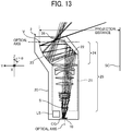
- FIG. 13 illustrates an example of a projection optical apparatus according to a first modification of the second embodiment.
- FIG. 13 illustrates the internal structure of the projection optical apparatus.
- the first modification differs from the projection optical apparatus according to the second embodiment in the lens structure of the refractive optical system 21.
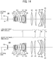
- FIG. 14 illustrates an example of the lens structure of the refractive optical system 21 according to the first modification and an example of the lens arrangement in accordance with a focus.
- FIG. 14 illustrates a lens arrangement 200 when focusing on the long-distance side (100 inches) is performed, and a lens arrangement 201 when focusing on the short-distance side (80 inches) is performed.
- the lens structure illustrated in FIG. 14 including a positive first lens group (I), a positive second lens group (II), a negative third lens group (III), and a negative fourth lens group (IV), will be described.
- the positive first lens group (I) includes the following lenses, in order from the image forming portion LV side: a biaspheric biconvex lens 311 whose convex surface having a stronger power faces the image forming portion LV side, a negative meniscus lens 312 whose convex surface faces the image forming portion LV side, an aperture stop S, a cemented lens including a negative meniscus lens 313 whose convex surface faces the image forming portion LV side and a plano-convex lens 314 whose convex surface faces the image forming portion LV side, a negative meniscus lens 315 whose convex surface faces the image forming portion LV side, a biaspheric biconvex lens 316 whose convex surface having a stronger power faces the magnification side, a negative meniscus lens 317 whose convex surface faces the image forming portion LV side, a cemented lens including a negative meniscus lens 318 whose convex surface faces the magnification side and a negative
- the positive second lens group (II) includes one biconvex lens 331 whose convex surface having a stronger power faces the image forming portion LV side.
- the negative third lens group (III) includes a negative meniscus lens 341 whose convex surface faces the magnification side, and a biaspheric negative meniscus resin lens 342 whose convex surface faces the image forming portion LV side.
- the negative fourth lens group (IV) includes a biaspheric negative meniscus resin lens 351 whose convex surface faces the magnification side.
- the curvature of the concave mirror 23, having a free-form surface, of the projection optical apparatus 2 is 0.
- Table 14 presents the positional coordinates of the concave mirror 23 having a free-form surface from the vertex of a lens that is positioned nearest to the reflective surface 22 in an in-focus state in which a projected image is the largest. Rotation is represented by the angle between a surface normal and the optical axis. Table 14 Y-axis Z-axis ⁇ 32nd Surface 0.00 66.68 -45.00 33rd Surface 71.62 86.23 -100.79
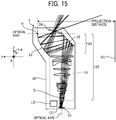
- FIG. 15 illustrates an example of a projection optical apparatus according to a second modification of the second embodiment.
- FIG. 16 illustrates an example of the lens structure of the refractive optical system 21 according to the second modification and an example of the lens arrangement in accordance with a focus.
- the second modification differs from the first modification in the lens diameter of the refractive optical system 21 of the projection optical apparatus.
- the positive first lens group (I) includes the following lenses, in order from the image forming portion LV side: a biaspheric biconvex lens 411 whose convex surface having a stronger power faces the image forming portion LV side, a negative meniscus lens 412 whose convex surface faces the image forming portion LV side, an aperture stop S, a cemented lens including a negative meniscus lens 413 whose convex surface faces the image forming portion LV side and a plano-convex lens 414 whose convex surface faces the image forming portion LV side, a negative meniscus lens 415 whose convex surface faces the image forming portion LV side, a biaspheric biconvex lens 416 whose convex surface having a stronger power faces the magnification side, a negative meniscus lens 417 whose convex surface faces the image forming portion LV side, a cemented lens including a negative meniscus lens 418 whose convex surface faces the magnification
- the positive second lens group (II) includes one biconvex lens 431 whose convex surface having a stronger power faces the image forming portion LV side.
- the negative third lens group (III) includes a negative meniscus lens 441 whose convex surface faces the magnification side, and a biaspheric negative meniscus resin lens 442 whose convex surface faces the image forming portion LV side.
- the negative fourth lens group (IV) includes a biaspheric negative meniscus resin lens 451 whose convex surface faces the magnification side.
- the NA of the refractive optical system 21 is 0.238, and the outside diameters of lenses are changed in accordance with the NA.
- the second modification is the same as the first modification of the second embodiment. Further descriptions of the second modification, which are the same as those of the first modification of the second embodiment, will be omitted.
- Table 15 presents examples of the values of parameters in the second embodiment, the first modification, and the second modification.
- Table 16 presents the values of the conditional expressions when these values of the parameters are input.
- Table 15 Parameter Second Embodiment First Modification Second Modification ⁇ 1 17 17 17 17 EP 39.0 30.1 30.1 Ym 6.48 6.48 ⁇ 2 39 38.5 38.5 U 22 18.6 14.4 BF 28 23 23 NA 0.29 0.29 0.238 Lcg 110 110 135 Lm 140 132 130
- Table 16 Second Embodiment First Modification Second Modification Conditional Expression (1) 17 17 17 Conditional Expression (2) 6.0 4.6 4.6 Conditional Expression (3) 39.0 38.5 38.5 Conditional Expression (4) 0.79 0.81 0.63 Conditional Expression (5) 0.29 0.29 0.238 Conditional Expression (6) 0.26 0.26 0.26 Conditional Expression (7) 0.79 0.83 1.04
- Tables 16 and 15 also include values to be set for a projection optical unit and a projection optical system. By setting the projection optical unit and the projection optical system as listed in Table 15, it is possible to reduce size and increase efficiency.
- the embodiments and the modifications are examples of a projection optical system unit, a projection optical system, and a projection optical apparatus.
- the structures of a projection optical system unit, a projection optical system, and a projection optical apparatus are not limited to these examples.
Landscapes
- Physics & Mathematics (AREA)
- General Physics & Mathematics (AREA)
- Optics & Photonics (AREA)
- Lenses (AREA)
- Projection Apparatus (AREA)
Claims (13)
- Optische Projektionssystemeinheit (1), die Folgendes umfasst:ein reflektierendes Bildanzeigeelement (10), das mehrere Mikrospiegel (100) umfasst, wobei das Bildanzeigeelement eine Bildanzeigeoberfläche aufweist, auf der die mehreren Mikrospiegel (100) zweidimensional angeordnet sind, und dafür konfiguriert ist, einen Winkel einer reflektierenden Oberfläche jedes der Mikrospiegel (100) in Bezug auf eine Linie senkrecht zur Bildanzeigeoberfläche zu ändern, um ein Bild zu erzeugen;ein optisches Beleuchtungssystem (LS), das dafür konfiguriert ist, die Bildanzeigeoberfläche zu beleuchten; undein optisches Projektionssystem (25), das Folgendes umfasst:mehrere Linsen (11) und eine Aperturblende (S), die dafür konfiguriert sind, ein durch das Bildanzeigeelement (10) erzeugtes Bild zu vergrößern und auf eine Projektionsoberfläche zu projizieren;dadurch gekennzeichnet, dass das optische Projektionssystem (25) Folgendes erfüllt:θ1 ≤ 15 Grad,3 < EP / Ym < 7 undθ2 > 30 Grad,wobei θ1 ein maximaler Neigungswinkel der reflektierenden Oberfläche jedes der Mikrospiegel (100) in Bezug auf die zur Bildanzeigeoberfläche senkrechte Linie ist,EP ein Eintrittspupillenabstand des optischen Projektionssystems (25) ist undYm ein maximaler Abstand in einer Ebene (C) von einer optischen Achse zu einem Punkt auf der Bildanzeigeoberfläche ist, wobei die Ebene (C) eine Ebene ist, in der ein Lichtstrahl existiert, der sich von einem Zentrum (LV0) der Bildanzeigeoberfläche zur Projektionsoberfläche durch ein Zentrum der Aperturblende (S) des optischen Projektionssystems (25) ausbreitet, wobei die optische Achse eine Achse ist, die von einer größten Anzahl der mehreren Linsen (11) des optischen Projektionssystems (25) gemeinsam genutzt wird, wobei der Punkt einem Bild auf der Projektionsoberfläche entspricht;θ2 ein Winkel, in Bezug auf die Linie senkrecht zur Bildanzeigeoberfläche, einer geraden Linie ist, die das Zentrum (LV0) der Bildanzeigeoberfläche und einen Oberflächenscheitelpunkt eines optischen Elements des optischen Beleuchtungssystems (LS) verbindet. wobei das optische Element der Bildanzeigeoberfläche am nächsten ist und Leistung aufweist.
- Optische Projektionssystemeinheit (1) nach Anspruch 1,
wobei eine orthogonale Projektion der geraden Linie auf die Bildanzeigeoberfläche parallel zu oder senkrecht zu einer langen Seite der Bildanzeigeoberfläche ist, wobei die gerade Linie das Zentrum (LV0) der Bildanzeigeoberfläche und den Oberflächenscheitelpunkt des optischen Elements des optischen Beleuchtungssystems (LS) verbindet, wobei das optische Element der Bildanzeigeoberfläche am nächsten liegt und Leistung aufweist. - Optische Projektionssystemeinheit (1) nach einem der Ansprüche 1 oder 2,
wobei 0,35 < U / BF < 0,85 erfüllt ist,
wobei BF ein Abstand entlang der optischen Achse zwischen der Bildanzeigeoberfläche und einem Scheitelpunkt einer Linsenoberfläche ist, der der Bildanzeigeoberfläche im optischen Projektionssystem (25) am nächsten liegt, und U ein Außendurchmesser eines Objektivs ist, dessen Linsenoberfläche der Bildanzeigeoberfläche am nächsten liegt. - Optische Projektionssystemeinheit (1) nach einem der Ansprüche 1 bis 3, die ferner Folgendes umfasst:eine flache Platte (CG) auf einem Lichtweg von der Bildanzeigeoberfläche zum optischen Projektionssystem (25),wobei in dem optischen Projektionssystem (25), in das vom optischen Beleuchtungssystem (LS) emittiertes und von der Bildanzeigeoberfläche reflektiertes Beleuchtungslicht über die flache Platte (CG) eintritt, eine Eintrittspupille (T), durch die das Beleuchtungslicht eintritt, sich durch eine Linse von der Bildanzeigeoberfläche entfernt befindet.
- Optische Projektionssystemeinheit (1) nach einem der Ansprüche 1 bis 4,
wobei NA > 0,17 erfüllt ist,
wobei NA eine numerische Apertur des optischen Projektionssystems (25) ist. - Optische Projektionssystemeinheit (1) nach einem der Ansprüche 1 bis 5,
wobei das optische Projektionssystem (25) in der Reihenfolge von der Seite der Bildanzeigeoberfläche Folgendes umfasst:ein optisches Brechungssystem (21), das die mehreren Linsen (11) und die Aperturblende (S) umfasst, undein optisches Reflexionssystem (24), das mindestens eine reflektierende Oberfläche (23) umfasst und Leistung aufweist. - Optische Projektionssystemeinheit (1) nach Anspruch 6,
wobei TR < 0,5 erfüllt ist,
wobei TR (ein Abstand von einem Schnittpunkt einer reflektierenden Oberfläche, die einer Vergrößerungsseite am nächsten liegt, und der optischen Achse in der reflektierenden Oberfläche zu einem Bildschirm, auf den das Bild vergrößert und projiziert wird) / (eine seitliche Breite des Bildschirms) ist. - Optische Projektionssystemeinheit (1) nach einem der Ansprüche 1 bis 7,
wobei in dem optischen Projektionssystem (25) die Aperturblende (S) zwischen mindestens zwei Linsen angeordnet ist. - Optische Projektionssystemeinheit (1) nach einem der Ansprüche 6 bis 8, die ferner Folgendes umfasst:ein staubdichtes Glas (26) zwischen einem Bildschirm und der reflektierenden Oberfläche (23), das Leistung aufweist,wobei 0,5 < Lcg / Lm < 1,8 erfüllt ist,wobei Lcg eine Länge des staubdichten Glases (26) ist und Lm eine Länge der reflektierenden Oberfläche (23) ist, die Leistung aufweist.
- Optische Projektionssystemeinheit (1) nach einem der Ansprüche 1 bis 9,
wobei die Bildanzeigeoberfläche die optische Achse nicht schneidet. - Optische Projektionssystemeinheit (1) nach einem der Ansprüche 6 bis 8,
wobei das optische Projektionssystem (25) ferner mindestens eine reflektierende Oberfläche zwischen dem optischen Brechungssystem (21) und der reflektierenden Oberfläche (23), die Leistung aufweist, umfasst und ein Lichtweg gebogen ist. - Optische Projektionssystemeinheit (1) nach einem der Ansprüche 1 bis 11,
wobei eine Linsengruppe des optischen Brechungssystems (21) eine positive Brechkraft aufweist, wobei die Linsengruppe der Bildanzeigeoberfläche am nächsten liegt. - Optische Projektionsvorrichtung (2) zum Vergrößern und Projizieren eines Bildes auf einen Bildschirm, wobei die optische Projektionsvorrichtung (2) Folgendes umfasst:
die optische Projektionssystemeinheit (1) nach Anspruch 1.
Applications Claiming Priority (1)
| Application Number | Priority Date | Filing Date | Title |
|---|---|---|---|
| JP2018050356A JP7234498B2 (ja) | 2018-03-19 | 2018-03-19 | 投射光学系ユニット及び投射光学装置 |
Publications (2)
| Publication Number | Publication Date |
|---|---|
| EP3543758A1 EP3543758A1 (de) | 2019-09-25 |
| EP3543758B1 true EP3543758B1 (de) | 2021-02-24 |
Family
ID=65724302
Family Applications (1)
| Application Number | Title | Priority Date | Filing Date |
|---|---|---|---|
| EP19161381.9A Active EP3543758B1 (de) | 2018-03-19 | 2019-03-07 | Optische projektionssystemeinheit, optisches projektionssystem und optische projektionsvorrichtung |
Country Status (4)
| Country | Link |
|---|---|
| US (1) | US10890840B2 (de) |
| EP (1) | EP3543758B1 (de) |
| JP (1) | JP7234498B2 (de) |
| CN (1) | CN110286549B (de) |
Families Citing this family (9)
| Publication number | Priority date | Publication date | Assignee | Title |
|---|---|---|---|---|
| TWI812715B (zh) * | 2018-06-29 | 2023-08-21 | 日商索尼股份有限公司 | 圖像顯示裝置及投射光學系統 |
| JP7120259B2 (ja) * | 2020-01-24 | 2022-08-17 | セイコーエプソン株式会社 | 投写光学系、およびプロジェクター |
| JP7424072B2 (ja) * | 2020-01-24 | 2024-01-30 | セイコーエプソン株式会社 | 投写光学系、およびプロジェクター |
| CN111580267B (zh) * | 2020-06-29 | 2022-03-22 | 歌尔光学科技有限公司 | 光学系统及投影装置 |
| JP7505334B2 (ja) * | 2020-08-31 | 2024-06-25 | 株式会社リコー | 画像投影装置 |
| DE102020125572A1 (de) * | 2020-09-30 | 2022-03-31 | Carl Zeiss Jena Gmbh | Projektionssystem |
| JP7476074B2 (ja) * | 2020-10-12 | 2024-04-30 | リコーインダストリアルソリューションズ株式会社 | 投射光学系および画像投射装置 |
| US12399422B2 (en) * | 2020-11-30 | 2025-08-26 | Sun Yang Optics Development Co., Ltd. | Projection optical system with a concave reflector in the projection lens |
| CN112764196B (zh) * | 2021-01-08 | 2022-03-11 | 广景视睿科技(深圳)有限公司 | 一种双远心投影镜头及汽车的抬头显示装置 |
Family Cites Families (43)
| Publication number | Priority date | Publication date | Assignee | Title |
|---|---|---|---|---|
| JP2003202492A (ja) | 2002-01-09 | 2003-07-18 | Matsushita Electric Ind Co Ltd | 投写レンズ及びそれを用いた投写型表示装置 |
| JP4470903B2 (ja) * | 2002-03-22 | 2010-06-02 | セイコーエプソン株式会社 | プロジェクタ |
| US20060028741A1 (en) * | 2004-08-04 | 2006-02-09 | 3M Innovative Properties Company | Projection lenses having color-correcting rear lens units |
| US7230770B2 (en) * | 2004-08-04 | 2007-06-12 | 3M Innovative Properties Company | Projection lenses having color-correcting rear lens units |
| CN100417969C (zh) * | 2004-10-21 | 2008-09-10 | 索尼株式会社 | 投影光学系统及投影型图像显示装置 |
| JP2007079524A (ja) | 2004-10-21 | 2007-03-29 | Sony Corp | 投射光学系及び投射型画像表示装置 |
| TWI289210B (en) * | 2004-10-21 | 2007-11-01 | Sony Corp | Projection optical system and projection type image display device |
| JP5041923B2 (ja) * | 2007-08-31 | 2012-10-03 | 株式会社日立製作所 | 投写光学ユニット、投写型映像表示装置及び投写型映像表示システム |
| JP2009251458A (ja) | 2008-04-09 | 2009-10-29 | Fujinon Corp | 投写光学系およびこれを用いた投写型表示装置 |
| US20090257117A1 (en) * | 2008-04-09 | 2009-10-15 | Tomoyuki Baba | Projection optical system and projection type display using the same |
| JP5484687B2 (ja) * | 2008-04-11 | 2014-05-07 | オリンパスイメージング株式会社 | ズームレンズを備えた撮像装置 |
| DE102008046699B4 (de) * | 2008-09-10 | 2014-03-13 | Carl Zeiss Smt Gmbh | Abbildende Optik |
| JP2010078627A (ja) * | 2008-09-24 | 2010-04-08 | Suwa Optronics:Kk | 投射型表示装置 |
| JP2010145917A (ja) | 2008-12-22 | 2010-07-01 | Samsung Electronics Co Ltd | 画像投影装置 |
| JP5703591B2 (ja) | 2010-05-18 | 2015-04-22 | 株式会社リコー | 投射光学系及び画像投射装置 |
| JP2012027113A (ja) * | 2010-07-21 | 2012-02-09 | Ricoh Co Ltd | 投射光学系及び画像投射装置 |
| JP5605211B2 (ja) | 2010-12-20 | 2014-10-15 | 株式会社リコー | 投射光学系及び画像投射装置 |
| JP5621583B2 (ja) | 2010-12-27 | 2014-11-12 | 株式会社リコー | 投射光学系及び画像投射装置 |
| JP5632782B2 (ja) | 2011-03-24 | 2014-11-26 | リコー光学株式会社 | 投射光学系および投射型画像表示装置 |
| US8705180B2 (en) | 2011-05-30 | 2014-04-22 | Ricoh Company, Ltd. | Zoom lens, imaging device and information device |
| JP5664920B2 (ja) | 2011-06-15 | 2015-02-04 | コニカミノルタ株式会社 | 投影レンズ及び投影装置 |
| EP2730961B1 (de) * | 2011-07-05 | 2020-03-25 | Nittoh Inc. | Optische projektionsanordnung und projektorvorrichtung |
| US8950874B2 (en) | 2011-09-16 | 2015-02-10 | Ricoh Company, Ltd. | Projection optical system and image display apparatus |
| JP5825047B2 (ja) * | 2011-10-28 | 2015-12-02 | 株式会社リコー | 画像表示装置 |
| JP5935131B2 (ja) | 2011-10-31 | 2016-06-15 | 株式会社リコー | 画像表示装置 |
| JP5849613B2 (ja) | 2011-10-31 | 2016-01-27 | 株式会社リコー | 画像表示装置 |
| JP6007478B2 (ja) * | 2011-11-02 | 2016-10-12 | 株式会社リコー | 画像表示装置 |
| CN102681357B (zh) * | 2012-04-01 | 2014-02-05 | 北京理工大学 | 一种极紫外光刻投影物镜设计方法 |
| CN102629082B (zh) * | 2012-04-28 | 2013-11-06 | 北京理工大学 | 一种极紫外光刻复眼照明系统的设计方法 |
| US9158119B2 (en) | 2012-10-31 | 2015-10-13 | Ricoh Company, Ltd. | Enlargement optical system |
| US8922883B2 (en) | 2012-11-05 | 2014-12-30 | Ricoh Company, Ltd. | Magnification optical system |
| JP6172431B2 (ja) | 2012-11-26 | 2017-08-02 | 株式会社リコー | 投射光学系 |
| JP6496977B2 (ja) | 2013-03-13 | 2019-04-10 | 株式会社リコー | 投射光学系、およびプロジェクタ装置 |
| JP6368988B2 (ja) | 2013-05-20 | 2018-08-08 | 株式会社リコー | 投射光学系および画像表示装置 |
| US10107996B2 (en) * | 2013-12-05 | 2018-10-23 | Delta Electronics, Inc. | Wide-angle projection optical system |
| JP6395029B2 (ja) | 2014-06-03 | 2018-09-26 | 株式会社リコー | 投射装置 |
| US9523842B2 (en) | 2014-06-23 | 2016-12-20 | Ricoh Company, Ltd. | Projection device and projection system |
| JP2017044870A (ja) | 2015-08-26 | 2017-03-02 | 株式会社リコー | 画像表示装置、画像表示ユニット |
| JP6604090B2 (ja) | 2015-08-27 | 2019-11-13 | 株式会社リコー | 投射光学系および投射装置および投射システム |
| TWI582521B (zh) * | 2016-04-15 | 2017-05-11 | 台達電子工業股份有限公司 | 光源模組 |
| JP6658351B2 (ja) | 2016-06-29 | 2020-03-04 | 株式会社リコー | 画像表示装置およびヘッドアップディスプレイシステム |
| JP6377815B2 (ja) * | 2017-07-05 | 2018-08-22 | 株式会社タムロン | 撮影レンズ及び撮影装置 |
| JP6500959B2 (ja) | 2017-10-02 | 2019-04-17 | 株式会社リコー | 投射装置 |
-
2018
- 2018-03-19 JP JP2018050356A patent/JP7234498B2/ja active Active
-
2019
- 2019-02-27 CN CN201910145042.7A patent/CN110286549B/zh active Active
- 2019-03-07 EP EP19161381.9A patent/EP3543758B1/de active Active
- 2019-03-17 US US16/355,765 patent/US10890840B2/en active Active
Non-Patent Citations (1)
| Title |
|---|
| None * |
Also Published As
| Publication number | Publication date |
|---|---|
| JP2019164176A (ja) | 2019-09-26 |
| US10890840B2 (en) | 2021-01-12 |
| CN110286549A (zh) | 2019-09-27 |
| JP7234498B2 (ja) | 2023-03-08 |
| EP3543758A1 (de) | 2019-09-25 |
| CN110286549B (zh) | 2021-06-01 |
| US20190285979A1 (en) | 2019-09-19 |
Similar Documents
| Publication | Publication Date | Title |
|---|---|---|
| EP3543758B1 (de) | Optische projektionssystemeinheit, optisches projektionssystem und optische projektionsvorrichtung | |
| US10761415B2 (en) | Projection optical system and projector apparatus | |
| US10067324B2 (en) | Projection device and projection system | |
| JP4016576B2 (ja) | 投射用レンズ装置および投射型画像表示装置 | |
| US7922340B2 (en) | Projection optical system with enlargement at a varying magnification | |
| JP4329863B2 (ja) | 投影光学系及び画像投影装置 | |
| EP1387201B1 (de) | Projektionsobjektiv und Projektor | |
| US8425044B2 (en) | Projection optical system | |
| US10928720B2 (en) | Projection optical system, image projection device and image projection system | |
| JP2009157223A (ja) | 斜め投射光学系 | |
| US8113667B2 (en) | Projection optical system | |
| JP2005301074A (ja) | 投影光学系 | |
| JP2020034690A (ja) | 投射光学系および画像投射装置 | |
| CN108027498A (zh) | 投射光学系统以及图像投射装置 | |
| JP2006178406A (ja) | 投影光学系 | |
| US7950806B2 (en) | Rear projector | |
| JP2015132723A (ja) | 投射光学系および画像表示装置 | |
| JP4767696B2 (ja) | 投写型画像表示装置 |
Legal Events
| Date | Code | Title | Description |
|---|---|---|---|
| PUAI | Public reference made under article 153(3) epc to a published international application that has entered the european phase |
Free format text: ORIGINAL CODE: 0009012 |
|
| STAA | Information on the status of an ep patent application or granted ep patent |
Free format text: STATUS: REQUEST FOR EXAMINATION WAS MADE |
|
| 17P | Request for examination filed |
Effective date: 20190307 |
|
| AK | Designated contracting states |
Kind code of ref document: A1 Designated state(s): AL AT BE BG CH CY CZ DE DK EE ES FI FR GB GR HR HU IE IS IT LI LT LU LV MC MK MT NL NO PL PT RO RS SE SI SK SM TR |
|
| AX | Request for extension of the european patent |
Extension state: BA ME |
|
| STAA | Information on the status of an ep patent application or granted ep patent |
Free format text: STATUS: EXAMINATION IS IN PROGRESS |
|
| 17Q | First examination report despatched |
Effective date: 20200519 |
|
| RIC1 | Information provided on ipc code assigned before grant |
Ipc: G02B 13/16 20060101AFI20200827BHEP Ipc: G03B 21/00 20060101ALI20200827BHEP Ipc: G03B 21/28 20060101ALI20200827BHEP Ipc: G02B 26/08 20060101ALI20200827BHEP |
|
| GRAP | Despatch of communication of intention to grant a patent |
Free format text: ORIGINAL CODE: EPIDOSNIGR1 |
|
| STAA | Information on the status of an ep patent application or granted ep patent |
Free format text: STATUS: GRANT OF PATENT IS INTENDED |
|
| INTG | Intention to grant announced |
Effective date: 20201007 |
|
| GRAS | Grant fee paid |
Free format text: ORIGINAL CODE: EPIDOSNIGR3 |
|
| GRAA | (expected) grant |
Free format text: ORIGINAL CODE: 0009210 |
|
| STAA | Information on the status of an ep patent application or granted ep patent |
Free format text: STATUS: THE PATENT HAS BEEN GRANTED |
|
| AK | Designated contracting states |
Kind code of ref document: B1 Designated state(s): AL AT BE BG CH CY CZ DE DK EE ES FI FR GB GR HR HU IE IS IT LI LT LU LV MC MK MT NL NO PL PT RO RS SE SI SK SM TR |
|
| REG | Reference to a national code |
Ref country code: CH Ref legal event code: EP |
|
| REG | Reference to a national code |
Ref country code: AT Ref legal event code: REF Ref document number: 1365211 Country of ref document: AT Kind code of ref document: T Effective date: 20210315 |
|
| REG | Reference to a national code |
Ref country code: IE Ref legal event code: FG4D |
|
| REG | Reference to a national code |
Ref country code: DE Ref legal event code: R096 Ref document number: 602019002652 Country of ref document: DE |
|
| REG | Reference to a national code |
Ref country code: LT Ref legal event code: MG9D |
|
| REG | Reference to a national code |
Ref country code: NL Ref legal event code: MP Effective date: 20210224 |
|
| PG25 | Lapsed in a contracting state [announced via postgrant information from national office to epo] |
Ref country code: NO Free format text: LAPSE BECAUSE OF FAILURE TO SUBMIT A TRANSLATION OF THE DESCRIPTION OR TO PAY THE FEE WITHIN THE PRESCRIBED TIME-LIMIT Effective date: 20210524 Ref country code: PT Free format text: LAPSE BECAUSE OF FAILURE TO SUBMIT A TRANSLATION OF THE DESCRIPTION OR TO PAY THE FEE WITHIN THE PRESCRIBED TIME-LIMIT Effective date: 20210624 Ref country code: LT Free format text: LAPSE BECAUSE OF FAILURE TO SUBMIT A TRANSLATION OF THE DESCRIPTION OR TO PAY THE FEE WITHIN THE PRESCRIBED TIME-LIMIT Effective date: 20210224 Ref country code: GR Free format text: LAPSE BECAUSE OF FAILURE TO SUBMIT A TRANSLATION OF THE DESCRIPTION OR TO PAY THE FEE WITHIN THE PRESCRIBED TIME-LIMIT Effective date: 20210525 Ref country code: FI Free format text: LAPSE BECAUSE OF FAILURE TO SUBMIT A TRANSLATION OF THE DESCRIPTION OR TO PAY THE FEE WITHIN THE PRESCRIBED TIME-LIMIT Effective date: 20210224 Ref country code: HR Free format text: LAPSE BECAUSE OF FAILURE TO SUBMIT A TRANSLATION OF THE DESCRIPTION OR TO PAY THE FEE WITHIN THE PRESCRIBED TIME-LIMIT Effective date: 20210224 Ref country code: BG Free format text: LAPSE BECAUSE OF FAILURE TO SUBMIT A TRANSLATION OF THE DESCRIPTION OR TO PAY THE FEE WITHIN THE PRESCRIBED TIME-LIMIT Effective date: 20210524 |
|
| REG | Reference to a national code |
Ref country code: AT Ref legal event code: MK05 Ref document number: 1365211 Country of ref document: AT Kind code of ref document: T Effective date: 20210224 |
|
| PG25 | Lapsed in a contracting state [announced via postgrant information from national office to epo] |
Ref country code: NL Free format text: LAPSE BECAUSE OF FAILURE TO SUBMIT A TRANSLATION OF THE DESCRIPTION OR TO PAY THE FEE WITHIN THE PRESCRIBED TIME-LIMIT Effective date: 20210224 Ref country code: RS Free format text: LAPSE BECAUSE OF FAILURE TO SUBMIT A TRANSLATION OF THE DESCRIPTION OR TO PAY THE FEE WITHIN THE PRESCRIBED TIME-LIMIT Effective date: 20210224 Ref country code: PL Free format text: LAPSE BECAUSE OF FAILURE TO SUBMIT A TRANSLATION OF THE DESCRIPTION OR TO PAY THE FEE WITHIN THE PRESCRIBED TIME-LIMIT Effective date: 20210224 Ref country code: LV Free format text: LAPSE BECAUSE OF FAILURE TO SUBMIT A TRANSLATION OF THE DESCRIPTION OR TO PAY THE FEE WITHIN THE PRESCRIBED TIME-LIMIT Effective date: 20210224 Ref country code: SE Free format text: LAPSE BECAUSE OF FAILURE TO SUBMIT A TRANSLATION OF THE DESCRIPTION OR TO PAY THE FEE WITHIN THE PRESCRIBED TIME-LIMIT Effective date: 20210224 |
|
| PG25 | Lapsed in a contracting state [announced via postgrant information from national office to epo] |
Ref country code: IS Free format text: LAPSE BECAUSE OF FAILURE TO SUBMIT A TRANSLATION OF THE DESCRIPTION OR TO PAY THE FEE WITHIN THE PRESCRIBED TIME-LIMIT Effective date: 20210624 |
|
| PG25 | Lapsed in a contracting state [announced via postgrant information from national office to epo] |
Ref country code: SM Free format text: LAPSE BECAUSE OF FAILURE TO SUBMIT A TRANSLATION OF THE DESCRIPTION OR TO PAY THE FEE WITHIN THE PRESCRIBED TIME-LIMIT Effective date: 20210224 Ref country code: AT Free format text: LAPSE BECAUSE OF FAILURE TO SUBMIT A TRANSLATION OF THE DESCRIPTION OR TO PAY THE FEE WITHIN THE PRESCRIBED TIME-LIMIT Effective date: 20210224 Ref country code: EE Free format text: LAPSE BECAUSE OF FAILURE TO SUBMIT A TRANSLATION OF THE DESCRIPTION OR TO PAY THE FEE WITHIN THE PRESCRIBED TIME-LIMIT Effective date: 20210224 Ref country code: CZ Free format text: LAPSE BECAUSE OF FAILURE TO SUBMIT A TRANSLATION OF THE DESCRIPTION OR TO PAY THE FEE WITHIN THE PRESCRIBED TIME-LIMIT Effective date: 20210224 |
|
| REG | Reference to a national code |
Ref country code: DE Ref legal event code: R097 Ref document number: 602019002652 Country of ref document: DE |
|
| PG25 | Lapsed in a contracting state [announced via postgrant information from national office to epo] |
Ref country code: DK Free format text: LAPSE BECAUSE OF FAILURE TO SUBMIT A TRANSLATION OF THE DESCRIPTION OR TO PAY THE FEE WITHIN THE PRESCRIBED TIME-LIMIT Effective date: 20210224 Ref country code: SK Free format text: LAPSE BECAUSE OF FAILURE TO SUBMIT A TRANSLATION OF THE DESCRIPTION OR TO PAY THE FEE WITHIN THE PRESCRIBED TIME-LIMIT Effective date: 20210224 Ref country code: RO Free format text: LAPSE BECAUSE OF FAILURE TO SUBMIT A TRANSLATION OF THE DESCRIPTION OR TO PAY THE FEE WITHIN THE PRESCRIBED TIME-LIMIT Effective date: 20210224 Ref country code: MC Free format text: LAPSE BECAUSE OF FAILURE TO SUBMIT A TRANSLATION OF THE DESCRIPTION OR TO PAY THE FEE WITHIN THE PRESCRIBED TIME-LIMIT Effective date: 20210224 |
|
| REG | Reference to a national code |
Ref country code: BE Ref legal event code: MM Effective date: 20210331 |
|
| PLBE | No opposition filed within time limit |
Free format text: ORIGINAL CODE: 0009261 |
|
| STAA | Information on the status of an ep patent application or granted ep patent |
Free format text: STATUS: NO OPPOSITION FILED WITHIN TIME LIMIT |
|
| PG25 | Lapsed in a contracting state [announced via postgrant information from national office to epo] |
Ref country code: ES Free format text: LAPSE BECAUSE OF FAILURE TO SUBMIT A TRANSLATION OF THE DESCRIPTION OR TO PAY THE FEE WITHIN THE PRESCRIBED TIME-LIMIT Effective date: 20210224 Ref country code: IE Free format text: LAPSE BECAUSE OF NON-PAYMENT OF DUE FEES Effective date: 20210307 Ref country code: LU Free format text: LAPSE BECAUSE OF NON-PAYMENT OF DUE FEES Effective date: 20210307 Ref country code: AL Free format text: LAPSE BECAUSE OF FAILURE TO SUBMIT A TRANSLATION OF THE DESCRIPTION OR TO PAY THE FEE WITHIN THE PRESCRIBED TIME-LIMIT Effective date: 20210224 |
|
| 26N | No opposition filed |
Effective date: 20211125 |
|
| PG25 | Lapsed in a contracting state [announced via postgrant information from national office to epo] |
Ref country code: SI Free format text: LAPSE BECAUSE OF FAILURE TO SUBMIT A TRANSLATION OF THE DESCRIPTION OR TO PAY THE FEE WITHIN THE PRESCRIBED TIME-LIMIT Effective date: 20210224 |
|
| PG25 | Lapsed in a contracting state [announced via postgrant information from national office to epo] |
Ref country code: IS Free format text: LAPSE BECAUSE OF FAILURE TO SUBMIT A TRANSLATION OF THE DESCRIPTION OR TO PAY THE FEE WITHIN THE PRESCRIBED TIME-LIMIT Effective date: 20210624 |
|
| PG25 | Lapsed in a contracting state [announced via postgrant information from national office to epo] |
Ref country code: BE Free format text: LAPSE BECAUSE OF NON-PAYMENT OF DUE FEES Effective date: 20210331 |
|
| REG | Reference to a national code |
Ref country code: CH Ref legal event code: PL |
|
| PG25 | Lapsed in a contracting state [announced via postgrant information from national office to epo] |
Ref country code: LI Free format text: LAPSE BECAUSE OF NON-PAYMENT OF DUE FEES Effective date: 20220331 Ref country code: CH Free format text: LAPSE BECAUSE OF NON-PAYMENT OF DUE FEES Effective date: 20220331 |
|
| P01 | Opt-out of the competence of the unified patent court (upc) registered |
Effective date: 20230522 |
|
| PG25 | Lapsed in a contracting state [announced via postgrant information from national office to epo] |
Ref country code: CY Free format text: LAPSE BECAUSE OF FAILURE TO SUBMIT A TRANSLATION OF THE DESCRIPTION OR TO PAY THE FEE WITHIN THE PRESCRIBED TIME-LIMIT Effective date: 20210224 |
|
| PG25 | Lapsed in a contracting state [announced via postgrant information from national office to epo] |
Ref country code: HU Free format text: LAPSE BECAUSE OF FAILURE TO SUBMIT A TRANSLATION OF THE DESCRIPTION OR TO PAY THE FEE WITHIN THE PRESCRIBED TIME-LIMIT; INVALID AB INITIO Effective date: 20190307 |
|
| PG25 | Lapsed in a contracting state [announced via postgrant information from national office to epo] |
Ref country code: MK Free format text: LAPSE BECAUSE OF FAILURE TO SUBMIT A TRANSLATION OF THE DESCRIPTION OR TO PAY THE FEE WITHIN THE PRESCRIBED TIME-LIMIT Effective date: 20210224 |
|
| PG25 | Lapsed in a contracting state [announced via postgrant information from national office to epo] |
Ref country code: TR Free format text: LAPSE BECAUSE OF FAILURE TO SUBMIT A TRANSLATION OF THE DESCRIPTION OR TO PAY THE FEE WITHIN THE PRESCRIBED TIME-LIMIT Effective date: 20210224 |
|
| PG25 | Lapsed in a contracting state [announced via postgrant information from national office to epo] |
Ref country code: MT Free format text: LAPSE BECAUSE OF FAILURE TO SUBMIT A TRANSLATION OF THE DESCRIPTION OR TO PAY THE FEE WITHIN THE PRESCRIBED TIME-LIMIT Effective date: 20210224 |
|
| PGFP | Annual fee paid to national office [announced via postgrant information from national office to epo] |
Ref country code: GB Payment date: 20260324 Year of fee payment: 8 |
|
| PGFP | Annual fee paid to national office [announced via postgrant information from national office to epo] |
Ref country code: DE Payment date: 20260319 Year of fee payment: 8 |
|
| PGFP | Annual fee paid to national office [announced via postgrant information from national office to epo] |
Ref country code: IT Payment date: 20260324 Year of fee payment: 8 |
|
| PGFP | Annual fee paid to national office [announced via postgrant information from national office to epo] |
Ref country code: FR Payment date: 20260320 Year of fee payment: 8 |