EP3543602B1 - Luminaire rectiligne - Google Patents
Luminaire rectiligne Download PDFInfo
- Publication number
- EP3543602B1 EP3543602B1 EP19163271.0A EP19163271A EP3543602B1 EP 3543602 B1 EP3543602 B1 EP 3543602B1 EP 19163271 A EP19163271 A EP 19163271A EP 3543602 B1 EP3543602 B1 EP 3543602B1
- Authority
- EP
- European Patent Office
- Prior art keywords
- support
- device carrier
- longitudinal direction
- light
- profile
- Prior art date
- Legal status (The legal status is an assumption and is not a legal conclusion. Google has not performed a legal analysis and makes no representation as to the accuracy of the status listed.)
- Active
Links
- 230000003287 optical effect Effects 0.000 claims description 47
- 238000001125 extrusion Methods 0.000 claims description 9
- 229910052782 aluminium Inorganic materials 0.000 claims description 8
- XAGFODPZIPBFFR-UHFFFAOYSA-N aluminium Chemical compound [Al] XAGFODPZIPBFFR-UHFFFAOYSA-N 0.000 claims description 8
- 238000000034 method Methods 0.000 claims description 8
- 238000001746 injection moulding Methods 0.000 claims description 6
- 229910052751 metal Inorganic materials 0.000 claims description 6
- 239000002184 metal Substances 0.000 claims description 6
- 229910000831 Steel Inorganic materials 0.000 claims description 5
- 239000010959 steel Substances 0.000 claims description 5
- 238000007493 shaping process Methods 0.000 claims 2
- 239000004411 aluminium Substances 0.000 claims 1
- 230000015572 biosynthetic process Effects 0.000 description 9
- 239000000969 carrier Substances 0.000 description 4
- 239000004020 conductor Substances 0.000 description 4
- 238000004519 manufacturing process Methods 0.000 description 4
- 238000011109 contamination Methods 0.000 description 2
- 230000000694 effects Effects 0.000 description 2
- 238000009434 installation Methods 0.000 description 2
- 208000027418 Wounds and injury Diseases 0.000 description 1
- 230000006378 damage Effects 0.000 description 1
- 230000001419 dependent effect Effects 0.000 description 1
- 238000007688 edging Methods 0.000 description 1
- 208000014674 injury Diseases 0.000 description 1
- 239000002245 particle Substances 0.000 description 1
- 230000000717 retained effect Effects 0.000 description 1
Images


Classifications
-
- F—MECHANICAL ENGINEERING; LIGHTING; HEATING; WEAPONS; BLASTING
- F21—LIGHTING
- F21V—FUNCTIONAL FEATURES OR DETAILS OF LIGHTING DEVICES OR SYSTEMS THEREOF; STRUCTURAL COMBINATIONS OF LIGHTING DEVICES WITH OTHER ARTICLES, NOT OTHERWISE PROVIDED FOR
- F21V31/00—Gas-tight or water-tight arrangements
- F21V31/005—Sealing arrangements therefor
-
- F—MECHANICAL ENGINEERING; LIGHTING; HEATING; WEAPONS; BLASTING
- F21—LIGHTING
- F21S—NON-PORTABLE LIGHTING DEVICES; SYSTEMS THEREOF; VEHICLE LIGHTING DEVICES SPECIALLY ADAPTED FOR VEHICLE EXTERIORS
- F21S8/00—Lighting devices intended for fixed installation
- F21S8/04—Lighting devices intended for fixed installation intended only for mounting on a ceiling or the like overhead structures
-
- F—MECHANICAL ENGINEERING; LIGHTING; HEATING; WEAPONS; BLASTING
- F21—LIGHTING
- F21V—FUNCTIONAL FEATURES OR DETAILS OF LIGHTING DEVICES OR SYSTEMS THEREOF; STRUCTURAL COMBINATIONS OF LIGHTING DEVICES WITH OTHER ARTICLES, NOT OTHERWISE PROVIDED FOR
- F21V15/00—Protecting lighting devices from damage
- F21V15/01—Housings, e.g. material or assembling of housing parts
- F21V15/013—Housings, e.g. material or assembling of housing parts the housing being an extrusion
-
- F—MECHANICAL ENGINEERING; LIGHTING; HEATING; WEAPONS; BLASTING
- F21—LIGHTING
- F21V—FUNCTIONAL FEATURES OR DETAILS OF LIGHTING DEVICES OR SYSTEMS THEREOF; STRUCTURAL COMBINATIONS OF LIGHTING DEVICES WITH OTHER ARTICLES, NOT OTHERWISE PROVIDED FOR
- F21V17/00—Fastening of component parts of lighting devices, e.g. shades, globes, refractors, reflectors, filters, screens, grids or protective cages
- F21V17/10—Fastening of component parts of lighting devices, e.g. shades, globes, refractors, reflectors, filters, screens, grids or protective cages characterised by specific fastening means or way of fastening
- F21V17/16—Fastening of component parts of lighting devices, e.g. shades, globes, refractors, reflectors, filters, screens, grids or protective cages characterised by specific fastening means or way of fastening by deformation of parts; Snap action mounting
- F21V17/164—Fastening of component parts of lighting devices, e.g. shades, globes, refractors, reflectors, filters, screens, grids or protective cages characterised by specific fastening means or way of fastening by deformation of parts; Snap action mounting the parts being subjected to bending, e.g. snap joints
-
- F—MECHANICAL ENGINEERING; LIGHTING; HEATING; WEAPONS; BLASTING
- F21—LIGHTING
- F21V—FUNCTIONAL FEATURES OR DETAILS OF LIGHTING DEVICES OR SYSTEMS THEREOF; STRUCTURAL COMBINATIONS OF LIGHTING DEVICES WITH OTHER ARTICLES, NOT OTHERWISE PROVIDED FOR
- F21V19/00—Fastening of light sources or lamp holders
- F21V19/001—Fastening of light sources or lamp holders the light sources being semiconductors devices, e.g. LEDs
- F21V19/003—Fastening of light source holders, e.g. of circuit boards or substrates holding light sources
- F21V19/0035—Fastening of light source holders, e.g. of circuit boards or substrates holding light sources the fastening means being capable of simultaneously attaching of an other part, e.g. a housing portion or an optical component
-
- F—MECHANICAL ENGINEERING; LIGHTING; HEATING; WEAPONS; BLASTING
- F21—LIGHTING
- F21V—FUNCTIONAL FEATURES OR DETAILS OF LIGHTING DEVICES OR SYSTEMS THEREOF; STRUCTURAL COMBINATIONS OF LIGHTING DEVICES WITH OTHER ARTICLES, NOT OTHERWISE PROVIDED FOR
- F21V19/00—Fastening of light sources or lamp holders
- F21V19/001—Fastening of light sources or lamp holders the light sources being semiconductors devices, e.g. LEDs
- F21V19/003—Fastening of light source holders, e.g. of circuit boards or substrates holding light sources
- F21V19/004—Fastening of light source holders, e.g. of circuit boards or substrates holding light sources by deformation of parts or snap action mountings, e.g. using clips
-
- F—MECHANICAL ENGINEERING; LIGHTING; HEATING; WEAPONS; BLASTING
- F21—LIGHTING
- F21V—FUNCTIONAL FEATURES OR DETAILS OF LIGHTING DEVICES OR SYSTEMS THEREOF; STRUCTURAL COMBINATIONS OF LIGHTING DEVICES WITH OTHER ARTICLES, NOT OTHERWISE PROVIDED FOR
- F21V21/00—Supporting, suspending, or attaching arrangements for lighting devices; Hand grips
- F21V21/02—Wall, ceiling, or floor bases; Fixing pendants or arms to the bases
- F21V21/025—Elongated bases having a U-shaped cross section
-
- F—MECHANICAL ENGINEERING; LIGHTING; HEATING; WEAPONS; BLASTING
- F21—LIGHTING
- F21V—FUNCTIONAL FEATURES OR DETAILS OF LIGHTING DEVICES OR SYSTEMS THEREOF; STRUCTURAL COMBINATIONS OF LIGHTING DEVICES WITH OTHER ARTICLES, NOT OTHERWISE PROVIDED FOR
- F21V5/00—Refractors for light sources
- F21V5/02—Refractors for light sources of prismatic shape
-
- F—MECHANICAL ENGINEERING; LIGHTING; HEATING; WEAPONS; BLASTING
- F21—LIGHTING
- F21V—FUNCTIONAL FEATURES OR DETAILS OF LIGHTING DEVICES OR SYSTEMS THEREOF; STRUCTURAL COMBINATIONS OF LIGHTING DEVICES WITH OTHER ARTICLES, NOT OTHERWISE PROVIDED FOR
- F21V5/00—Refractors for light sources
- F21V5/04—Refractors for light sources of lens shape
-
- F—MECHANICAL ENGINEERING; LIGHTING; HEATING; WEAPONS; BLASTING
- F21—LIGHTING
- F21Y—INDEXING SCHEME ASSOCIATED WITH SUBCLASSES F21K, F21L, F21S and F21V, RELATING TO THE FORM OR THE KIND OF THE LIGHT SOURCES OR OF THE COLOUR OF THE LIGHT EMITTED
- F21Y2103/00—Elongate light sources, e.g. fluorescent tubes
- F21Y2103/10—Elongate light sources, e.g. fluorescent tubes comprising a linear array of point-like light-generating elements
-
- F—MECHANICAL ENGINEERING; LIGHTING; HEATING; WEAPONS; BLASTING
- F21—LIGHTING
- F21Y—INDEXING SCHEME ASSOCIATED WITH SUBCLASSES F21K, F21L, F21S and F21V, RELATING TO THE FORM OR THE KIND OF THE LIGHT SOURCES OR OF THE COLOUR OF THE LIGHT EMITTED
- F21Y2115/00—Light-generating elements of semiconductor light sources
- F21Y2115/10—Light-emitting diodes [LED]
Definitions
- the invention relates to a straight and longitudinally extending luminaire for a light strip according to the preamble of claim 1.
- Luminaires for a light strip are already known from the prior art.
- the light band usually comprises several straight luminaires that are mounted in a row on a wall or on a ceiling.
- the respective luminaire usually comprises a support profile with a current guide rail, on which a device carrier with a light source plate is fixed.
- the light source plate with several light sources is supplied with power via the power supply rail and controlled by a control device in the support profile.
- the device carrier is usually closed with an optics cover through which the light generated by the light sources is scattered.
- Many components have to be assembled in the luminaire, which makes assembly more difficult and increases manufacturing costs.
- DE 10 2013 216 275 A1 a generic lamp with a support profile, a device carrier and an optical cover is disclosed.
- the equipment rack is attached to the support profile by means of a clamp and the lens cover is attached to the equipment rack by means of a tongue and groove connection.
- the object of the invention is to provide an improved or at least alternative embodiment for the luminaire of the generic type in which the disadvantages described are overcome.
- the present invention is based on the general idea of assembling individual components in a luminaire and thereby simplifying the assembly of the luminaire.
- the straight and longitudinally extending lamp is intended for a light band and has an elongated U-shaped support profile and an elongated U-shaped device carrier which is positively fixed to the support profile.
- the device carrier closes the support profile transversely to the longitudinal direction at least in some areas with a profile locking base and a profile interior is thereby formed in the support profile.
- the luminaire also has at least one elongated optics cover that is attached to the device carrier.
- the at least one optics cover closes the device carrier transversely to the longitudinal direction and a carrier interior is thereby formed in the device carrier.
- the lamp also has at least one elongated light support plate with several light sources, which is fixed in the carrier interior of the device carrier.
- the lamp has at least two elongated V-shaped retaining clips, each with a first support wing and a second support wing, which are each connected to one another by a support edge.
- the respective retaining clip is supported in the carrier interior with the first support wing on the luminous support plate, with the second support wing on the at least one optics cover and with the support edge on an elongated support contour of the device carrier.
- the luminous support plate and the at least one optics cover are also fixed in the carrier interior towards the support profile on the device carrier so that the holding effect of the retaining clip can be reinforced by the weight of the luminous support plate and the weight of the optics cover.
- the holding effect of the retaining clip in the lamp according to the invention can be reinforced by the weight of the light support plate and by the weight of the optics cover.
- the weight force is then from the luminous support plate and from the optics cover directed towards the elongated support contour of the device carrier, so that the retaining clip is reinforced on the support contour as a result.
- the retaining clip according to the invention can thereby be used for secure, sustainable fastening of the luminous support plate and the optical cover in the interior of the support to care.
- the support profile can have a current guide rail with several electrical conductors, which can supply the several light sources on the luminous support plate with power.
- an electrical connection element can be provided on the luminous support plate, by means of which the multiple light sources on the luminous support plate can be connected to the power supply rail.
- the electrical connection element can engage in the power supply rail and in this way electrically connect the multiple light sources to at least one of the conductors of the power supply rail.
- connection element can also be electrically connected to a control device that can control the multiple light sources individually or in groups.
- the plurality of light sources are arranged on a front side of the luminous support plate, which is arranged facing the optics cover in the carrier interior.
- the electrical connection element can then appropriately be fixed on a rear side of the luminous support plate facing away from the front side and thereby facing the profile interior.
- the device carrier is closed with at least one optical cover.
- the at least one optical cover is expediently designed to be at least partially and at least partially light-transparent.
- the luminaire can, for example, have a single lens cover that closes the device carrier transversely to the longitudinal direction.
- several - and preferably two - optical covers can also be provided, which are arranged next to one another transversely to the longitudinal direction and close the device carrier transversely to the longitudinal direction.
- the carrier interior can be divided in the longitudinal direction by at least one intermediate flange of the device carrier and the respective optics cover can then be fixed on one side between a flange of the device carrier and the respective intermediate flange adjacent to the flange, or alternatively between two adjacent intermediate flanges.
- the respective intermediate flange can expediently have the inner contour of the facing flange on both sides, so that the optics cover can be fixed to it.
- the distance between the flanges in an equipment rack without an intermediate flange and the distance between the flanges and the respective intermediate flange and the intermediate flanges from one another in an equipment rack with the respective intermediate flange can be the same.
- the optics cover, the luminous support plate as well as further components arranged in the device carrier can then remain configured in the same way in a device carrier with and without the at least one intermediate flange.
- the luminous support plate and the optics cover are advantageously fixed together in the interior of the support and additional fastening means are dispensed with. This allows both the production costs to be reduced and the assembly of the lamp to be simplified.
- the retaining clip can advantageously also ensure that the luminous support plate and the optics cover are securely and sustainably fastened in the interior of the support.
- the retaining clip according to the invention makes dismantling of the optics cover more difficult, so that the risk of injury to a person who is not responsible is reduced.
- the respective retaining clip presses the luminous support plate in the carrier interior onto the device carrier towards the carrier profile through the first support wing.
- the light support plate rests against the device carrier and the heat generated in the light support plate can be dissipated to the device carrier.
- the respective retaining clip presses the at least one optics cover into the through the second support wing Carrier interior to the light support plate to the support profile.
- the luminous support plate is pressed against the device carrier and the optics cover on the luminous support plate is pressed towards the support profile.
- the optics cover thereby encloses the light sources fixed on the light support plate transversely to the longitudinal direction and the light sources on the light support plate can thereby be better protected from contamination.
- the first support wing of the respective retaining clip has at least one first beveled bevel area and at least one second beveled bevel area.
- the respective folding areas are folded transversely to the longitudinal direction and extend in the longitudinal direction.
- the at least one first folded area can fix the luminous support plate towards the supporting profile on the device carrier and the at least one second folded zone can fix the luminous supporting plate parallel to the supporting profile and laterally transversely to the longitudinal direction.
- the at least one first folding area and the at least one second folding area both act transversely to the longitudinal direction, so that the luminous support plate is fixed on the device carrier such that it can be displaced in the longitudinal direction.
- thermal expansion of the luminous support plate in and across the longitudinal direction can thereby be compensated for and distortion of the luminous support plate during operation of the lamp can advantageously be prevented.
- a retaining clip can be arranged on both sides of the light support plate, so that the light support plate lies against the device carrier and is fixed transversely to the longitudinal direction through the folding areas of the first support wing of the respective retaining clips.
- the respective second folded areas of the first support wing of the respective retaining clips do not prevent any thermal expansion of the luminous support plate transversely to the longitudinal direction, so that a distortion of the light support plate during operation of the lamp can advantageously be prevented.
- the second support wing of the respective retaining clip has at least one third beveled bevel region which is beveled transversely to the longitudinal direction and extends in the longitudinal direction.
- the third folding area defines the at least one optical cover towards the luminous support plate.
- the third folded area of the second support wing of the respective retaining clip can bear against a support surface of the optics cover that extends in the longitudinal direction in order to enable a large-area contact of the second support wing with the optics cover.
- a plurality of tips can be integrally formed on the supporting edge of the respective retaining clip.
- the tips fix the retaining clip in the longitudinal direction on the respective support contour of the device carrier.
- a seal extending in the longitudinal direction is arranged between the at least one optics cover and the device carrier.
- the seal is supported on one side on the device carrier and on the other side on the at least one optical system cover and fixes the at least one optical system cover to the support profile in the carrier interior.
- the seal can press the luminous support plate onto the device carrier towards the support profile.
- this allows the optics cover to be securely attached to the device carrier and an undesired detachment of the optics cover from the device carrier can be prevented.
- the seal can be elastic, for example, to prevent deformation of the optics cover or the To compensate device carrier due to thermal expansion during operation of the luminaire.
- the seal can advantageously be injection-molded onto the at least one optics cover in order to reduce the manufacturing costs.
- the device carrier has a light support base which is arranged parallel to and spaced apart from the profile locking base and extends in the longitudinal direction.
- the light support base divides the support interior into a light interior with the at least one light support plate and a heat insulating space which is arranged in the longitudinal direction between the profile interior and the light interior.
- the luminous support plate with the multiple light sources is then arranged in the luminous interior adjacent to the luminous support base and can be fixed - for example pressed on - to the latter by the respective retaining clips.
- the heat insulating space is arranged between the light interior and the profile interior and isolates the profile interior and the light interior from one another.
- the direct heat transfer between the luminous support plate with the multiple light sources and electrical or electronic components in the profile interior - such as a control device, for example - can be minimized.
- the heat generated in the luminaire can preferably be dissipated to the outside and the functionality of the luminaire can advantageously be retained.
- the profile locking base is integrally formed by at least one projection facing the support profile on the luminous support base of the device carrier, the projection having a T-shaped cross section transversely to the longitudinal direction and extending in the longitudinal direction.
- the profile locking base can be attached by means of two lateral projections be integrally formed with the light support base of the device carrier, the projections facing one another and extending in the longitudinal direction.
- Both the support profile and electrical or electronic components in the profile interior - such as a control device - can be supported on the respective projections.
- the respective projection expediently extends in the longitudinal direction over an entire length of the device carrier, so that the profile interior and the light interior are separated from one another in a heat-insulating manner over an entire length of the lamp.
- the light support base has at least one guide formation for centering the light support plate.
- the guide formation is directed into the light interior and extends in the longitudinal direction.
- the guide formation facilitates a centered fixing of the light support plate with the multiple light sources in the light interior, whereby the assembly of the light is simplified.
- the equipment carrier can advantageously be clamped in the support profile on both sides in the longitudinal direction.
- the assembly and disassembly of the device carrier on the support profile can be simplified as a result.
- flanges of the device carrier can be arranged in the profile interior and clamped between flanges of the support profile in the longitudinal direction over an entire length of the support profile or the device carrier.
- a clamping arrangement with a clamping groove and a clamping spring which extend in the longitudinal direction and can be brought into engagement with one another transversely to the longitudinal direction, can be provided on both sides.
- the respective clamping spring or clamping groove are then integrally formed on the outside on the flanges of the device carrier and the respective clamping groove or clamping spring on the inside on the flanges of the support profile.
- the equipment carrier can have a handle groove arrangement on both sides with a plurality of preferably parallel handle grooves.
- the respective grip groove arrangement extends on the outside on a flange of the device carrier in the longitudinal direction.
- the device carrier is an extruded part formed from aluminum in an extrusion process.
- the equipment carrier can be a shaped sheet metal part formed from sheet steel.
- the at least one optics cover is centered on the device carrier by a centering arrangement in and transverse to the longitudinal direction and is fixed so that it can be extended in the longitudinal direction.
- Centering arrangement can for example comprise a centering formation and a centering recess which can be brought into engagement with one another transversely to the longitudinal direction.
- the respective centering recess or centering formation can then be formed on the optics cover and the respective centering formation or centering recess can be formed, for example, on the luminous support plate.
- optics arranged in the optics cover can be aligned relative to the multiple light sources of the light support plate and optical losses in the luminaire can thereby be reduced.
- the centering arrangement also does not prevent thermal expansion of the optics cover in the longitudinal direction and distortion of the optics cover during operation of the lamp can advantageously be prevented.
- the at least one optics cover has a plurality of integrally formed prisms.
- the optical cover is then preferably produced in an extrusion process.
- the at least one optical cover can be several integrally have molded lenses.
- the optics cover is then preferably produced in an injection molding process.
- the at least one optics cover can advantageously consist of several optics cover parts which are arranged one behind the other on the device carrier in the longitudinal direction. In particular, the production of an elongated optical cover in an injection molding process can thereby be simplified.
- the optics cover can then advantageously have a centering arrangement which is integrated into the lenses.
- one of the lenses can have a centering recess and the luminous support plate can have a centering formation which interlock and fix the lens on the luminous support plate in and across the longitudinal direction.
- the optics cover or also the optics cover parts can have at least one identification arrangement which is integrally formed on both sides of the optics cover transversely to the longitudinal direction.
- the identification arrangement can, for example, have an identification projection and an identification recess which can be brought into engagement with the identification projection, which prevents incorrect installation of the optical covers or the optical cover parts on one another in the longitudinal direction and also simplifies the installation of the lamp.
- additional fastening means can be avoided in the luminaire according to the invention by the retaining clip and the assembly can thereby be simplified; the heat generated in the luminaire is preferably dissipated to the outside through the heat insulating space and the functionality of the luminaire is advantageously preserved; the interior of the light is protected from dirt particles by the seal and the optics cover is securely attached to the device carrier; and through the centering arrangement on the optics cover Thermal expansion of the optics cover is compensated and optical losses are advantageously reduced.
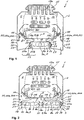
- Fig. 1 shows a view of a lamp 1 according to the invention.
- the lamp 1 has an elongated U-shaped support profile 2 and an elongated U-shaped device carrier 3, which is fixed to the support profile 2 in a form-fitting manner.
- the equipment carrier 3 closes the support profile 2 transversely to the longitudinal direction 4 with a profile locking base 5, so that a profile interior 6 is formed in the support profile 2.
- the luminaire 1 also has an elongated optics cover 7, which is fixed to the device carrier 3.
- the optics cover 7 has a plurality of prisms 8a formed integrally in the optics cover 7 and can be produced in an extrusion process.
- the optics cover 7 closes the device carrier 3 transversely to the longitudinal direction 4, so that a carrier interior 9 is formed in the device carrier 3.
- the device carrier 3 has a luminous support base 10, which is arranged parallel to and at a distance from the profile locking base 5 and extends in the longitudinal direction 4.
- the light support base 10 divides the support interior 9 into a light interior 9a and a heat insulating space 9b.
- a light support plate 11 with a plurality of light sources 12 is fixed on the light support base 10 on both sides by a retaining clip 13 in each case.
- a seal 14 is arranged on both sides, which is supported on the optics cover 7 and on the device carrier 3 and seals the luminous interior 9a from the outside.
- the support profile 2 has a current guide rail 15 with several electrical conductors 15a, which supply the several light sources 12 on the luminous support plate 11 with current.
- an electrical connection element - not visible here - is provided on the luminous support plate 11, by means of which the multiple light sources 12 on the luminous support plate 11 are electrically conductively connected to the conductors 15a of the power supply rail 15 via a control device 16.
- the control device 16 can control the multiple light sources 12 individually or in groups.
- the control device 16 is arranged in the profile interior 6 and is supported on the profile locking base 5.
- the profile interior is through the heat insulating space 9b 6 with the control device 16 from the luminous interior 9a with the luminous support plate 11 is thermally insulated.
- the device carrier 3 is a shaped sheet metal part and the profile locking base 5 is integrally formed by two lateral projections 17a on the luminous support base 10 of the device carrier 3.
- the projections 17a face one another and extend in the longitudinal direction 4 over an entire length of the device carrier 3.
- the equipment rack 3 is clamped in the support profile 2 on both sides.
- flanges 18 of the device carrier 3 are arranged in the profile interior 6 and clamped between flanges 19 of the support profile 2 in the longitudinal direction 4 over an entire length of the support profile 2 or the device carrier 3.
- a clamping arrangement 20 with a clamping spring 20a and a clamping groove 20b is integrally formed on both sides.
- the clamping spring 20a and the clamping groove 20b engage one another and extend in the longitudinal direction 4.
- the support profile 2 is supported on the equipment carrier 3 on both sides on a respective support formation 21.
- the device carrier 3 has a handle groove arrangement 22 on both sides with a plurality of preferably parallel handle grooves 23.
- the respective grip groove arrangement 22 extends on the outside on the respective flange 18 of the device carrier 3 in the longitudinal direction 4.
- the luminous support plate 11 with the light sources 12 is arranged in the luminous interior 9a in contact with the luminous support base 10 and is pressed against the latter on both sides by the retaining clips 13.
- the light support plate 11 rests on the light support base 10 and the heat generated in the light support plate 11 by the light sources 12 can be dissipated to the outside through the device carrier 3.
- the luminous support base 10 is separated from the control device 16 by the heat insulating space 9b, so that a direct heat transfer between the luminous support plate 11 and the control device 16 is advantageously prevented.
- a guide formation 24 aligned in the luminous interior 9a is integrally formed, which centers the luminous support plate 11 in the luminous interior 9a transversely to the longitudinal direction 4.
- the respective retaining clip 13 has a first support wing 25a and a second support wing 25b, which are connected to one another by a support edge 26.
- the respective retaining clip 13 is supported with the first support wing 25a on the luminous support plate 11, with the second support wing 25b on the optics cover 7 and with the support edge 26 on an elongated support contour 27 of the device carrier 3.
- the respective retaining clip 13 is resilient and presses the luminous support plate 11 against the luminous support base 10 through the first support wing 25a and the optics cover 7 against the luminous support plate 11 through the second support wing 25b. In this way, the luminous support plate 11 is fixed on the luminous support base 10 and the optics cover 7 on the luminous support plate 11.
- the optics cover 7 is pressed against the luminous support plate 11 by the seal 14, which is supported on one side on the device carrier 3 and on the other side on the optics cover 7.
- the retaining clip 13 is fixed to the support contour 27 of the device carrier 3 in the longitudinal direction 4 by a plurality of tips 28 formed integrally on the support edge 26.
- the optics cover 7 encloses the light sources 12 fixed on the luminous support plate 11 transversely to the longitudinal direction 4 and the light sources 12 are thereby protected from contamination.
- the luminous interior 9a is also sealed off from the outside by the seal 14.
- the seal 14 can, for example, be elastic and injection-molded onto the optics cover 7.
- the lamp can 1 by cover caps - not shown here - be sealed on both sides in the longitudinal direction to the outside.
- Fig. 2 shows a view of the lamp 1 according to the invention in a different embodiment.
- the equipment rack 3 has a structure that differs from the equipment rack 3 in FIG Fig. 1 on. Otherwise, the structure of the lamp 1 shown here corresponds to the structure of the in Fig. 1 shown lamp 1.
- the equipment carrier 3 is an extruded part formed from aluminum in an extrusion process.
- the profile locking base 5 is integrally formed by two T-shaped projections 17b facing the support profile 2 on the luminous support base 10 of the device carrier 3.
- the device carrier 3 has, in contrast to the one shown in FIG Fig. 1
- the device carrier 3 shown has an intermediate flange 18a which divides the light interior 9a in the longitudinal direction 4 and is closed by two optics covers 7 arranged next to one another.
- the respective optics cover 7 is fixed on one side between the flange 18 and the intermediate flange 18a of the device carrier 3.
- the intermediate flange 18a has an inner contour of the facing flange 18 on both sides.
- the device carrier 3 is shaped in such a way that the respective optics cover 7, the support profile 2 and other components of the lamp 1 according to the invention remain the same.
- the equipment rack 3 shown here and the one in FIG Fig. 1 Device carrier 3 shown in the lamp 1 according to the invention can be interchanged with one another.
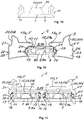
- Fig. 3 shows a view of the lamp 1 according to the invention in a different embodiment.
- the optics cover 7 has a structure that differs from the optics cover 7 in FIG Fig. 1 on. Otherwise, the structure of the lamp 1 shown here corresponds to the structure of the in Fig. 1 shown lamp 1.
- the optics cover 7 differs from the optics cover in FIG Fig. 1 a plurality of lenses 8b formed integrally on the optical cover 7.
- the optics cover 7 also has a centering recess 29b of a centering arrangement 29 on one of the lenses 8b, into which a centering recess 29a - here the light source 12 on the luminous support plate 11 - engages and in this way centers the lens 8b on the light source 12 and in and across to the longitudinal direction 4 on the light source 12.
- the thermal expansion of the optics cover 7 is not prevented to the side of the centering recess 29b and distortion of the optics cover 7 is advantageously avoided.
- the optics cover 7 can for example be produced in an injection molding process and consist of several optics cover parts arranged one behind the other in the longitudinal direction 4.
- the optics cover 7 is shaped in such a way that the support profile 2, the device carrier 3 and other components of the lamp 1 according to the invention remain the same.
- the optical cover 7 shown here and the one in FIG FIGS. 1 and 2 Optical covers 7 shown in the lamp 1 according to the invention are interchangeable with one another.
- Fig. 4 shows a view of the lamp 1 according to the invention in a different embodiment.
- the optics cover 7 has a structure that differs from the optics cover 7 in FIG Fig. 2 on. Otherwise, the structure of the lamp 1 shown here corresponds to the structure of the in Fig. 2 1.
- the device carrier 3 has a structure that differs from the device carrier 3 in FIG Fig. 3 on. Otherwise, the structure of the lamp 1 shown here corresponds to the structure of the in Fig. 3 shown lamp 1.
- the equipment carrier 3 is an extruded part formed from aluminum in an extrusion process.
- the profile locking base 5 is integrally formed by the T-shaped projections 17b facing the support profile 2 on the luminous support base 10 of the device carrier 3.
- the device carrier 3 also has different from that in Fig. 3
- the device carrier 3 shown has the intermediate flange 18a which divides the luminous interior 9a in the longitudinal direction 4.
- the respective optics cover 7 with the lenses 8b is fixed on one side between the flange 18 and the intermediate flange 18a of the device carrier 3.
- the device carrier 3 is shaped in such a way that the respective optics cover 7, the support profile 2 and other components of the lamp 1 according to the invention remain the same.
- the equipment rack 3 shown here and the one in FIG Fig. 3 Device carrier 3 shown in the lamp 1 according to the invention can be interchanged with one another.
- the optics cover 7 shown has a plurality of lenses 8b formed integrally on the optics cover 7.
- the optics cover 7 also has the centering recess 29b of the centering arrangement 29 on one of the lenses 8b, through which the optics cover 7 is centered on the luminous support plate 11.
- the optics cover 7 can for example be produced in an injection molding process and consist of several optics cover parts arranged one behind the other in the longitudinal direction 4.
- the optics cover 7 is shaped in such a way that the support profile 2, the device carrier 3 and other components of the lamp 1 according to the invention remain the same.
- the optical covers 7 shown here and those in FIG Fig. 2 Optical covers 7 shown in the lamp 1 according to the invention are interchangeable with one another.
- FIG. 11 shows a partial view of the device carrier 3 with the retaining clip 13 in a first embodiment, as shown in FIGS. 1 to 4 is shown.
- Fig. 6 is a View of the in Fig. 5 retaining clip 13 shown.
- the retaining clip 13 has the first support wing 25a and the second support wing 25b, which are connected to one another by the support edge 26.
- the respective retaining clip 13 is supported with the first support wing 25a on the luminous support plate 11, with the second support wing 25b on the optics cover 7 and with the support edge 26 on the elongated support contour 27 of the device carrier 3.
- the respective retaining clip 13 presses the luminous support plate 11 against the luminous support base 10 through the first support wing 25a and the optics cover 7 against the luminous support plate 11 through the second support wing 25b. In this way, the luminous support plate 11 is fixed on the luminous support base 10 and the optics cover 7 on the luminous support plate 11. As a result of the plurality of tips 28 formed integrally on the support edge 26, the retaining clip 13 is also fixed to the support contour 27 of the device carrier 3 in the longitudinal direction 4.
- the first support wing 25a has a first beveled bevel region 30 and two second beveled bevel regions 31.
- the folded areas 30 and 31 are folded transversely to the longitudinal direction 4 and extend in the longitudinal direction 4.
- the first folded area 30 presses the luminous support plate 11 towards the luminous support base 10 and the two second folded regions 31 fix the luminous support plate 11 laterally on the luminous support base 10.
- the folded regions 30 and 31 act transversely to the longitudinal direction 4, so that the luminous support plate 11 is fixed on the luminous support base 10 such that it can be displaced in the longitudinal direction 4.
- a thermal expansion of the luminous support plate 11 in the longitudinal direction 4 can thereby be compensated and a distortion of the luminous support plate 11 during operation of the luminaire 1 can advantageously be prevented.
- the second support wing 25b of the retaining clip 13 has a third beveled bevel region 32 which is beveled transversely to the longitudinal direction 5 and extends in the longitudinal direction 4.
- the third edging region 32 presses the optics cover 7 to form the luminous support plate 11 and lies against a support surface 33 of the optics cover 7 that extends in the longitudinal direction 4.
- FIG. 11 shows a partial view of the device carrier 3 with the retaining clip 13 in a second embodiment, as shown in FIGS. 1 to 4 is shown.
- Fig. 8 is a view of the in Fig. 7 retaining clip 13 shown.
- the second folded regions 31 of the first support wing 25a of the retaining clip 13 are different from the second folded regions 31 in FIG FIGS. 5 and 6 shown retaining clip configured.
- the structure of the retaining clip 13 here corresponds to the structure of the retaining clip 13 in the first embodiment.
- FIG. 11 shows a view of the device carrier 3 like this one in FIG Fig. 1 and Fig. 3 is shown.
- the device carrier 3 is here a shaped sheet metal part made of sheet steel.
- Fig. 10 shows a view of the device carrier 3, which differs from the device carrier 3 from Fig. 9 is an extrusion made of aluminum.
- the profile locking base 5 is formed by T-shaped projections 17b, otherwise the device carrier 3 shown here corresponds to that in FIG Fig. 9 Device carrier 3 shown. Both device carriers 3 are interchangeable in the light 1.
- FIG. 11 shows a view of the device carrier 3 like this one in FIG Fig.
- the device carrier 3 is here an extruded part made of aluminum.
- the light interior 9a is divided by the intermediate flange 18a and two optical covers 7 with prisms 8a or with lenses 8b can be fixed on the device carrier 3.
- the profile locking base 5 is formed by T-shaped projections 17b.
- the equipment rack 3 shown here corresponds to the equipment racks 3 from Figures 9 and 10 so that they can be interchanged in the lamp 1.
- Fig. 12 shows a view of the optics cover 7 with the prisms 8a.
- Fig. 12 and in Fig. 13 are views of the in Fig. 12 shown optics cover 7 is shown, which is built into the differently configured equipment carrier 3.
- the optical cover 7 shown here can for example be produced in an extrusion process and the prisms 8a can be coextruded.
- the seal 14 is injection-molded onto the optics cover 7 and seals the interior 9a of the light to the outside and additionally presses the optics cover 7 onto the light support base 10.
- the optics cover 7 with the prisms 8a is built into the variously configured equipment mounts 3.
- the device carrier 3 corresponds to that in Fig. 1 , Fig.
- Fig. 9 shown equipment carrier 3 and is a sheet metal part made of sheet steel.
- the device carrier 3 corresponds to that in Fig. 2 , Fig. 4 or Fig. 11 shown device carrier 3 and is an extruded part made of aluminum.
- Fig. 15 shows a view of the optics cover 7 with the lenses 8b.
- Fig. 16 and in Fig. 17 are views of the in Fig. 15 shown optics cover 7 is shown, which is built into the differently configured equipment carrier 3.
- the optics cover 7 shown here can for example be produced in an injection molding process and consist of several optics cover parts.
- the seal 14 is injection-molded onto the optics cover 7 and seals the interior 9a of the light to the outside and additionally presses the optics cover 7 onto the light support base 10.
- the optics cover 7 with the lenses 8b is built into the variously configured equipment mounts 3.
- the device carrier 3 corresponds to that in Fig. 1 , Fig. 3 or Fig. 9 shown equipment carrier 3 and is a sheet metal part made of sheet steel.
- the device carrier 3 corresponds to that in Fig. 2 , Fig. 4 or Fig. 11 shown device carrier 3 and is an extruded part made of aluminum.
- the heat insulating space 9b prevents a direct heat transfer between the luminous support plate 11 and the control device 16, whereby the functionality of the luminaire 1 is advantageously preserved.
- the retaining clip 13 eliminates the need for additional fasteners and the assembly of the lamp 1 is significantly simplified.
- the seal 14 advantageously seals the light interior 9a to the outside and additionally supports the optics cover 7 in the device carrier 3.
- the centering arrangement 29 on the optics cover 7 enables the lenses 8b to be centered on the light sources 12 and does not prevent the optics cover 7 from thermal expansion. In particular, a distortion of the luminous support plate 11 can thereby be prevented and optical losses in the luminaire 1 can advantageously be reduced.
Landscapes
- Engineering & Computer Science (AREA)
- General Engineering & Computer Science (AREA)
- Securing Globes, Refractors, Reflectors Or The Like (AREA)
- Non-Portable Lighting Devices Or Systems Thereof (AREA)
Claims (17)
- Luminaire (1) rectiligne et s'étendant dans le sens longitudinal (4) pour une bande lumineuse,- dans lequel le luminaire (1) présente un profil porteur (2) oblong en forme de U et un support d'appareil (3) oblong en forme de U qui est fixé par complémentarité de formes au profil porteur (2),- dans lequel le support d'appareil (3) ferme le profil porteur (2) transversalement au sens longitudinal (4) au moins par endroits avec un fond de fermeture de profil (5) et un espace intérieur de profil (6) est ainsi formé dans le profil porteur (2),- dans lequel le luminaire (1) présente au moins un recouvrement optique (7) oblong qui est fixé au support d'appareil (3),- dans lequel l'au moins un recouvrement optique (7) ferme le support d'appareil (3) transversalement au sens longitudinal (4) et un espace intérieur de support (9) est ainsi formé dans le support d'appareil (3),- dans lequel le luminaire (1) présente au moins une plaque porteuse de luminaire (11) oblongue avec plusieurs sources de lumière (12) qui est fixée dans l'espace intérieur de support (9) du support d'appareil (3),- dans lequel le luminaire (1) présente au moins deux agrafes de retenue (13) oblongues en forme de V avec respectivement une première aile d'appui (25a) et avec une seconde aile d'appui (25b) qui sont reliées respectivement par une arête d'appui (26) entre elles,caractérisée en ce que- que l'agrafe de retenue (13) respective s'appuie dans l'espace intérieur de support (9) avec la première aile d'appui (25a) contre la plaque porteuse de luminaire (11), avec la seconde aile d'appui (25b) contre l'au moins un recouvrement optique (7) et avec l'arête d'appui (26) contre un contour d'appui (27) oblong du support d'appareil (3), et- que la plaque porteuse de luminaire (11) et l'au moins un recouvrement optique (7) sont fixés dans l'espace intérieur de support (9) vers le profil porteur (2) au support d'appareil (3) et l'action de retenue de l'agrafe de retenue (13) peut ainsi être renforcée par le poids de la plaque porteuse de luminaire (11) et par le poids du recouvrement optique (7).
- Luminaire selon la revendication 1,
caractérisé en ce- que l'agrafe de retenue (13) respective presse par la première aile d'appui (25a) la plaque porteuse de luminaire (11) contre le support d'appareil (3) vers le profil porteur (2), et- que l'agrafe de retenue (13) respective presse par la seconde aile d'appui (25b) l'au moins un recouvrement optique (7) contre la plaque porteuse de luminaire (11) vers le profil porteur (2). - Luminaire selon la revendication 1 ou 2,
caractérisé en ce- que la première aile d'appui (25a) de l'agrafe de retenue (13) respective présente au moins une première zone de chanfrein (30) chanfreinée et au moins une deuxième zone de chanfrein (31) chanfreinée, dans lequel les zones de chanfrein (30, 31) respectives sont chanfreinées transversalement au sens longitudinal (4) et s'étendent dans le sens longitudinal (4), et- que l'au moins une première zone de chanfrein (30) fixe la plaque porteuse de luminaire (11) vers l'espace intérieur de profil (6) et l'au moins une deuxième zone de chanfrein (31) fixe la plaque porteuse de luminaire (11) parallèlement à l'espace intérieur de profil (6) et transversalement au sens longitudinal (4) latéralement. - Luminaire selon l'une des revendications précédentes,
caractérisé en ce- que la seconde aile d'appui (25b) de l'agrafe de retenue (13) respective présente au moins une troisième zone de chanfrein (32) chanfreinée qui est chanfreinée transversalement au sens longitudinal (4) et s'étend dans le sens longitudinal (4), et- que la troisième zone de chanfrein (32) fixe l'au moins un recouvrement optique (7) vers la plaque porteuse de luminaire (11). - Luminaire selon l'une des revendications précédentes,
caractérisé en ce- que plusieurs pointes (28) sont formées d'un seul tenant au niveau de l'arête d'appui (26) de l'agrafe de retenue (13) respective qui fixent l'agrafe de retenue (13) dans le sens longitudinal (4) au contour d'appui (27) respectif du support d'appareil (3). - Luminaire selon l'une des revendications précédentes,
caractérisé en ce
qu'une garniture (14) s'étendant dans le sens longitudinal (4) est agencée entre l'au moins un recouvrement optique (7) et le support d'appareil (3), laquelle s'appuie d'un côté contre le support d'appareil (3) et de l'autre côté contre l'au moins un recouvrement optique (7) et fixe l'au moins un recouvrement optique (7) vers le profil porteur (2) dans l'espace intérieur de support (9). - Luminaire selon la revendication 6,
caractérisé en ce- que la garniture (14) presse la plaque porteuse de luminaire (11) contre le support d'appareil (3) vers le profil porteur (2), et/ou- que la garniture (14) est élastique, et/ou- que la garniture (14) est moulée par injection sur l'au moins un recouvrement optique (7). - Luminaire selon l'une des revendications précédentes,
caractérisé en ce- que le support d'appareil (3) présente un fond porteur de luminaire (10) qui est agencé parallèlement et à distance du fond de fermeture de profil (5) et s'étend dans le sens longitudinal (4), et- que le fond porteur de luminaire (10) sépare l'espace intérieur de support (9) en un espace intérieur de luminaire (9a) avec l'au moins une plaque porteuse de luminaire (11) et un espace thermoisolant (9b) qui est agencé dans le sens longitudinal (4) entre l'espace intérieur de profil (6) et l'espace intérieur de luminaire (9a). - Luminaire selon la revendication 8,
caractérisé en ce- que le fond de fermeture de profil (5) est réalisé d'un seul tenant par deux saillies (17a) latérales sur le fond porteur de luminaire (10) du support d'appareil (3), dans lequel les saillies (17a) sont tournées l'une vers l'autre et s'étendent dans le sens longitudinal (4), ou- que le fond de fermeture de profil (5) est réalisé d'un seul tenant par au moins une saillie (17b) tournée vers le profil porteur (2) au niveau du fond porteur de luminaire (100) du support d'appareil (3), dans lequel la saillie (17b) présente transversalement au sens longitudinal (4) une section transversale en forme de T et s'étend dans le sens longitudinal (4). - Luminaire selon la revendication 8 ou 9,
caractérisé en ce- que le fond porteur de luminaire (10) présente au moins une forme de guidage (24) pour le centrage de la plaque porteuse de luminaire (11), dans lequel la forme de guidage (24) est dirigée dans l'espace intérieur de luminaire (10) et s'étend dans le sens longitudinal (4). - Luminaire selon l'une des revendications précédentes,
caractérisé en ce- que le support d'appareil (3) est une partie extrudée formée dans un procédé d'extrusion en aluminium, ou- que le support d'appareil (3) est une partie moulée en tôle formée en tôle d'acier. - Luminaire selon l'une des revendications précédentes,
caractérisé en ce
que le support d'appareil (3) est serré des deux côtés dans le profil porteur (2) dans le sens longitudinal (4). - Luminaire selon l'une des revendications précédentes,
caractérisé en ce
que le support d'appareil (3) présente des deux côtés respectivement un agencement de rainures de préhension (21) avec plusieurs rainures de préhension (22) de préférence parallèles, dans lequel l'agencement de rainures de préhension (21) respectif s'étend côté extérieur au niveau d'une bride (18) du support d'appareil (3) dans le sens longitudinal (4). - Luminaire selon l'une des revendications précédentes,
caractérisé en ce
que l'au moins un recouvrement optique (7) se compose de plusieurs parties de recouvrement optique qui sont agencées au niveau du support d'appareil (3) dans le sens longitudinal (4) les unes derrière les autres. - Luminaire selon l'une des revendications précédentes,
caractérisé en ce- que l'au moins un recouvrement optique (7) est centré au niveau du support d'appareil (3) par un agencement de centrage (29) dans et transversalement au sens longitudinal (4) et est fixé de manière extensible dans le sens longitudinal (4), et/ou- que le recouvrement optique (7) présente au moins un agencement d'identification pour exclure une erreur de montage, dans lequel l'agencement d'identification est réalisé d'un seul tenant au niveau du recouvrement optique (7) des deux côtés transversalement au sens longitudinal (4). - Luminaire selon l'une des revendications précédentes,
caractérisé en ce- que l'au moins un recouvrement optique (7) présente plusieurs prismes (8a) formés d'un seul tenant et est fabriqué de préférence dans un procédé d'extrusion, ou- que l'au moins un recouvrement optique (7) présente plusieurs lentilles (8b) formées d'un seul tenant et est fabriqué de préférence dans un procédé de moulage par injection. - Luminaire selon la revendication 16,
caractérisé en ce
que l'au moins un recouvrement optique (7) présente les plusieurs lentilles (8b) dans lequel une des lentilles (8b) est fixée par l'agencement de centrage (29) dans et transversalement au sens longitudinal (4) à la plaque porteuse de luminaire (11).
Priority Applications (1)
| Application Number | Priority Date | Filing Date | Title |
|---|---|---|---|
| PL19163271T PL3543602T3 (pl) | 2018-03-16 | 2019-03-15 | Prostoliniowa oprawa oświetleniowa |
Applications Claiming Priority (1)
| Application Number | Priority Date | Filing Date | Title |
|---|---|---|---|
| DE202018101486.2U DE202018101486U1 (de) | 2018-03-16 | 2018-03-16 | Geradlinige Leuchte |
Publications (2)
| Publication Number | Publication Date |
|---|---|
| EP3543602A1 EP3543602A1 (fr) | 2019-09-25 |
| EP3543602B1 true EP3543602B1 (fr) | 2021-05-05 |
Family
ID=62117530
Family Applications (1)
| Application Number | Title | Priority Date | Filing Date |
|---|---|---|---|
| EP19163271.0A Active EP3543602B1 (fr) | 2018-03-16 | 2019-03-15 | Luminaire rectiligne |
Country Status (3)
| Country | Link |
|---|---|
| EP (1) | EP3543602B1 (fr) |
| DE (1) | DE202018101486U1 (fr) |
| PL (1) | PL3543602T3 (fr) |
Families Citing this family (2)
| Publication number | Priority date | Publication date | Assignee | Title |
|---|---|---|---|---|
| US10704770B2 (en) * | 2018-09-11 | 2020-07-07 | CP IP Holdings Limited | Lighting arrangement |
| DE102018128752A1 (de) * | 2018-11-15 | 2020-05-20 | Trilux Gmbh & Co. Kg | Abgedichtete Leuchte |
Family Cites Families (3)
| Publication number | Priority date | Publication date | Assignee | Title |
|---|---|---|---|---|
| DE102013216275B4 (de) * | 2013-07-15 | 2015-07-02 | Ridi Leuchten Gmbh | Leuchte |
| CH709009B1 (de) * | 2013-12-18 | 2017-09-29 | Regent Beleuchtungskörper Ag | Befestigung einer Leiterplatte und einer Optik einer Leuchte. |
| DE202015102516U1 (de) * | 2015-05-15 | 2015-07-23 | Siteco Beleuchtungstechnik Gmbh | Klammerelement zur Befestigung einer Platine mit LEDs in einer Leuchte |
-
2018
- 2018-03-16 DE DE202018101486.2U patent/DE202018101486U1/de active Active
-
2019
- 2019-03-15 EP EP19163271.0A patent/EP3543602B1/fr active Active
- 2019-03-15 PL PL19163271T patent/PL3543602T3/pl unknown
Also Published As
| Publication number | Publication date |
|---|---|
| EP3543602A1 (fr) | 2019-09-25 |
| DE202018101486U1 (de) | 2018-04-20 |
| PL3543602T3 (pl) | 2021-11-08 |
Similar Documents
| Publication | Publication Date | Title |
|---|---|---|
| EP3543604B1 (fr) | Luminaire rectiligne | |
| EP2298582B1 (fr) | Dispositif de chauffage électrique et son procédé de fabrication | |
| EP3543602B1 (fr) | Luminaire rectiligne | |
| EP2705297B1 (fr) | Unité d'éclairage pour véhicules | |
| DE102010017346A1 (de) | Leuchte für einen Fachboden eines Möbels | |
| EP3056805B1 (fr) | Optique allongée pour module à del | |
| EP3543606B1 (fr) | Luminaire rectiligne | |
| EP2145783A2 (fr) | Chauffage de véhicule | |
| EP2264363A1 (fr) | Lampe, capuchon terminal et bande lumineuse | |
| EP2145782B1 (fr) | Chauffage de véhicule | |
| DE102009006439A1 (de) | Scheinwerferbefestigung an einem Fahrzeug | |
| EP2266823A1 (fr) | Dispositif de chauffage électrique | |
| EP0539621B1 (fr) | Système d'éclairage modulaire de locaux | |
| EP3543601A1 (fr) | Luminaire rectiligne | |
| DE10029102B4 (de) | Vorrichtung zum Befestigen einer Leuchte | |
| DE4438491C1 (de) | Leuchte für Fahrzeuge | |
| EP1389711B1 (fr) | Lampe à encastrer | |
| EP2982904B1 (fr) | Luminaire | |
| EP3246623B1 (fr) | Éclairage comprenant une carte de circuit imprimé del sur un support de tôle | |
| DE202020000689U1 (de) | Steuervorrichtung sowie elektrische Heizvorrichtung umfassend eine solche | |
| DE19757927C1 (de) | Signalleuchte für Fahrzeuge | |
| DE102004052348B4 (de) | Kraftfahrzeugleuchte | |
| EP2568215A2 (fr) | Lampe à bande lumineuse | |
| DE102012215840A1 (de) | Kraftfahrzeug mit einem Airbagmodul | |
| DE102021212614B4 (de) | Optik für eine Leuchte und Leuchte mit Optik |
Legal Events
| Date | Code | Title | Description |
|---|---|---|---|
| PUAI | Public reference made under article 153(3) epc to a published international application that has entered the european phase |
Free format text: ORIGINAL CODE: 0009012 |
|
| STAA | Information on the status of an ep patent application or granted ep patent |
Free format text: STATUS: THE APPLICATION HAS BEEN PUBLISHED |
|
| AK | Designated contracting states |
Kind code of ref document: A1 Designated state(s): AL AT BE BG CH CY CZ DE DK EE ES FI FR GB GR HR HU IE IS IT LI LT LU LV MC MK MT NL NO PL PT RO RS SE SI SK SM TR |
|
| AX | Request for extension of the european patent |
Extension state: BA ME |
|
| STAA | Information on the status of an ep patent application or granted ep patent |
Free format text: STATUS: REQUEST FOR EXAMINATION WAS MADE |
|
| 17P | Request for examination filed |
Effective date: 20200320 |
|
| RBV | Designated contracting states (corrected) |
Designated state(s): AL AT BE BG CH CY CZ DE DK EE ES FI FR GB GR HR HU IE IS IT LI LT LU LV MC MK MT NL NO PL PT RO RS SE SI SK SM TR |
|
| GRAP | Despatch of communication of intention to grant a patent |
Free format text: ORIGINAL CODE: EPIDOSNIGR1 |
|
| STAA | Information on the status of an ep patent application or granted ep patent |
Free format text: STATUS: GRANT OF PATENT IS INTENDED |
|
| RIC1 | Information provided on ipc code assigned before grant |
Ipc: F21V 31/00 20060101ALN20201020BHEP Ipc: F21S 8/04 20060101ALI20201020BHEP Ipc: F21V 5/02 20060101ALN20201020BHEP Ipc: F21Y 115/10 20160101ALN20201020BHEP Ipc: F21V 19/00 20060101AFI20201020BHEP Ipc: F21Y 103/10 20160101ALN20201020BHEP Ipc: F21V 21/02 20060101ALI20201020BHEP Ipc: F21V 5/04 20060101ALN20201020BHEP Ipc: F21V 15/01 20060101ALN20201020BHEP Ipc: F21V 17/16 20060101ALI20201020BHEP |
|
| INTG | Intention to grant announced |
Effective date: 20201111 |
|
| GRAS | Grant fee paid |
Free format text: ORIGINAL CODE: EPIDOSNIGR3 |
|
| GRAA | (expected) grant |
Free format text: ORIGINAL CODE: 0009210 |
|
| STAA | Information on the status of an ep patent application or granted ep patent |
Free format text: STATUS: THE PATENT HAS BEEN GRANTED |
|
| AK | Designated contracting states |
Kind code of ref document: B1 Designated state(s): AL AT BE BG CH CY CZ DE DK EE ES FI FR GB GR HR HU IE IS IT LI LT LU LV MC MK MT NL NO PL PT RO RS SE SI SK SM TR |
|
| REG | Reference to a national code |
Ref country code: GB Ref legal event code: FG4D Free format text: NOT ENGLISH |
|
| REG | Reference to a national code |
Ref country code: CH Ref legal event code: EP |
|
| REG | Reference to a national code |
Ref country code: AT Ref legal event code: REF Ref document number: 1390261 Country of ref document: AT Kind code of ref document: T Effective date: 20210515 |
|
| REG | Reference to a national code |
Ref country code: DE Ref legal event code: R096 Ref document number: 502019001340 Country of ref document: DE |
|
| REG | Reference to a national code |
Ref country code: IE Ref legal event code: FG4D Free format text: LANGUAGE OF EP DOCUMENT: GERMAN |
|
| REG | Reference to a national code |
Ref country code: LT Ref legal event code: MG9D |
|
| PG25 | Lapsed in a contracting state [announced via postgrant information from national office to epo] |
Ref country code: FI Free format text: LAPSE BECAUSE OF FAILURE TO SUBMIT A TRANSLATION OF THE DESCRIPTION OR TO PAY THE FEE WITHIN THE PRESCRIBED TIME-LIMIT Effective date: 20210505 Ref country code: LT Free format text: LAPSE BECAUSE OF FAILURE TO SUBMIT A TRANSLATION OF THE DESCRIPTION OR TO PAY THE FEE WITHIN THE PRESCRIBED TIME-LIMIT Effective date: 20210505 Ref country code: HR Free format text: LAPSE BECAUSE OF FAILURE TO SUBMIT A TRANSLATION OF THE DESCRIPTION OR TO PAY THE FEE WITHIN THE PRESCRIBED TIME-LIMIT Effective date: 20210505 Ref country code: BG Free format text: LAPSE BECAUSE OF FAILURE TO SUBMIT A TRANSLATION OF THE DESCRIPTION OR TO PAY THE FEE WITHIN THE PRESCRIBED TIME-LIMIT Effective date: 20210805 |
|
| PG25 | Lapsed in a contracting state [announced via postgrant information from national office to epo] |
Ref country code: SE Free format text: LAPSE BECAUSE OF FAILURE TO SUBMIT A TRANSLATION OF THE DESCRIPTION OR TO PAY THE FEE WITHIN THE PRESCRIBED TIME-LIMIT Effective date: 20210505 Ref country code: RS Free format text: LAPSE BECAUSE OF FAILURE TO SUBMIT A TRANSLATION OF THE DESCRIPTION OR TO PAY THE FEE WITHIN THE PRESCRIBED TIME-LIMIT Effective date: 20210505 Ref country code: PT Free format text: LAPSE BECAUSE OF FAILURE TO SUBMIT A TRANSLATION OF THE DESCRIPTION OR TO PAY THE FEE WITHIN THE PRESCRIBED TIME-LIMIT Effective date: 20210906 Ref country code: LV Free format text: LAPSE BECAUSE OF FAILURE TO SUBMIT A TRANSLATION OF THE DESCRIPTION OR TO PAY THE FEE WITHIN THE PRESCRIBED TIME-LIMIT Effective date: 20210505 Ref country code: NO Free format text: LAPSE BECAUSE OF FAILURE TO SUBMIT A TRANSLATION OF THE DESCRIPTION OR TO PAY THE FEE WITHIN THE PRESCRIBED TIME-LIMIT Effective date: 20210805 Ref country code: GR Free format text: LAPSE BECAUSE OF FAILURE TO SUBMIT A TRANSLATION OF THE DESCRIPTION OR TO PAY THE FEE WITHIN THE PRESCRIBED TIME-LIMIT Effective date: 20210806 Ref country code: IS Free format text: LAPSE BECAUSE OF FAILURE TO SUBMIT A TRANSLATION OF THE DESCRIPTION OR TO PAY THE FEE WITHIN THE PRESCRIBED TIME-LIMIT Effective date: 20210905 |
|
| REG | Reference to a national code |
Ref country code: NL Ref legal event code: MP Effective date: 20210505 |
|
| PG25 | Lapsed in a contracting state [announced via postgrant information from national office to epo] |
Ref country code: NL Free format text: LAPSE BECAUSE OF FAILURE TO SUBMIT A TRANSLATION OF THE DESCRIPTION OR TO PAY THE FEE WITHIN THE PRESCRIBED TIME-LIMIT Effective date: 20210505 |
|
| PG25 | Lapsed in a contracting state [announced via postgrant information from national office to epo] |
Ref country code: EE Free format text: LAPSE BECAUSE OF FAILURE TO SUBMIT A TRANSLATION OF THE DESCRIPTION OR TO PAY THE FEE WITHIN THE PRESCRIBED TIME-LIMIT Effective date: 20210505 Ref country code: ES Free format text: LAPSE BECAUSE OF FAILURE TO SUBMIT A TRANSLATION OF THE DESCRIPTION OR TO PAY THE FEE WITHIN THE PRESCRIBED TIME-LIMIT Effective date: 20210505 Ref country code: SK Free format text: LAPSE BECAUSE OF FAILURE TO SUBMIT A TRANSLATION OF THE DESCRIPTION OR TO PAY THE FEE WITHIN THE PRESCRIBED TIME-LIMIT Effective date: 20210505 Ref country code: DK Free format text: LAPSE BECAUSE OF FAILURE TO SUBMIT A TRANSLATION OF THE DESCRIPTION OR TO PAY THE FEE WITHIN THE PRESCRIBED TIME-LIMIT Effective date: 20210505 Ref country code: CZ Free format text: LAPSE BECAUSE OF FAILURE TO SUBMIT A TRANSLATION OF THE DESCRIPTION OR TO PAY THE FEE WITHIN THE PRESCRIBED TIME-LIMIT Effective date: 20210505 Ref country code: RO Free format text: LAPSE BECAUSE OF FAILURE TO SUBMIT A TRANSLATION OF THE DESCRIPTION OR TO PAY THE FEE WITHIN THE PRESCRIBED TIME-LIMIT Effective date: 20210505 Ref country code: SM Free format text: LAPSE BECAUSE OF FAILURE TO SUBMIT A TRANSLATION OF THE DESCRIPTION OR TO PAY THE FEE WITHIN THE PRESCRIBED TIME-LIMIT Effective date: 20210505 |
|
| REG | Reference to a national code |
Ref country code: DE Ref legal event code: R097 Ref document number: 502019001340 Country of ref document: DE |
|
| PLBE | No opposition filed within time limit |
Free format text: ORIGINAL CODE: 0009261 |
|
| STAA | Information on the status of an ep patent application or granted ep patent |
Free format text: STATUS: NO OPPOSITION FILED WITHIN TIME LIMIT |
|
| 26N | No opposition filed |
Effective date: 20220208 |
|
| PG25 | Lapsed in a contracting state [announced via postgrant information from national office to epo] |
Ref country code: IS Free format text: LAPSE BECAUSE OF FAILURE TO SUBMIT A TRANSLATION OF THE DESCRIPTION OR TO PAY THE FEE WITHIN THE PRESCRIBED TIME-LIMIT Effective date: 20210905 Ref country code: AL Free format text: LAPSE BECAUSE OF FAILURE TO SUBMIT A TRANSLATION OF THE DESCRIPTION OR TO PAY THE FEE WITHIN THE PRESCRIBED TIME-LIMIT Effective date: 20210505 |
|
| PG25 | Lapsed in a contracting state [announced via postgrant information from national office to epo] |
Ref country code: IT Free format text: LAPSE BECAUSE OF FAILURE TO SUBMIT A TRANSLATION OF THE DESCRIPTION OR TO PAY THE FEE WITHIN THE PRESCRIBED TIME-LIMIT Effective date: 20210505 |
|
| PG25 | Lapsed in a contracting state [announced via postgrant information from national office to epo] |
Ref country code: MC Free format text: LAPSE BECAUSE OF FAILURE TO SUBMIT A TRANSLATION OF THE DESCRIPTION OR TO PAY THE FEE WITHIN THE PRESCRIBED TIME-LIMIT Effective date: 20210505 |
|
| REG | Reference to a national code |
Ref country code: CH Ref legal event code: PL |
|
| REG | Reference to a national code |
Ref country code: BE Ref legal event code: MM Effective date: 20220331 |
|
| PG25 | Lapsed in a contracting state [announced via postgrant information from national office to epo] |
Ref country code: LU Free format text: LAPSE BECAUSE OF NON-PAYMENT OF DUE FEES Effective date: 20220315 Ref country code: LI Free format text: LAPSE BECAUSE OF NON-PAYMENT OF DUE FEES Effective date: 20220331 Ref country code: IE Free format text: LAPSE BECAUSE OF NON-PAYMENT OF DUE FEES Effective date: 20220315 Ref country code: CH Free format text: LAPSE BECAUSE OF NON-PAYMENT OF DUE FEES Effective date: 20220331 |
|
| PG25 | Lapsed in a contracting state [announced via postgrant information from national office to epo] |
Ref country code: BE Free format text: LAPSE BECAUSE OF NON-PAYMENT OF DUE FEES Effective date: 20220331 |
|
| PGFP | Annual fee paid to national office [announced via postgrant information from national office to epo] |
Ref country code: FR Payment date: 20230523 Year of fee payment: 5 Ref country code: DE Payment date: 20230530 Year of fee payment: 5 |
|
| PGFP | Annual fee paid to national office [announced via postgrant information from national office to epo] |
Ref country code: PL Payment date: 20230511 Year of fee payment: 5 |
|
| PGFP | Annual fee paid to national office [announced via postgrant information from national office to epo] |
Ref country code: GB Payment date: 20230522 Year of fee payment: 5 |
|
| PG25 | Lapsed in a contracting state [announced via postgrant information from national office to epo] |
Ref country code: MK Free format text: LAPSE BECAUSE OF FAILURE TO SUBMIT A TRANSLATION OF THE DESCRIPTION OR TO PAY THE FEE WITHIN THE PRESCRIBED TIME-LIMIT Effective date: 20210505 Ref country code: CY Free format text: LAPSE BECAUSE OF FAILURE TO SUBMIT A TRANSLATION OF THE DESCRIPTION OR TO PAY THE FEE WITHIN THE PRESCRIBED TIME-LIMIT Effective date: 20210505 |
|
| PGFP | Annual fee paid to national office [announced via postgrant information from national office to epo] |
Ref country code: DE Payment date: 20240328 Year of fee payment: 6 Ref country code: GB Payment date: 20240319 Year of fee payment: 6 |