EP3543602B1 - Linear luminaire - Google Patents
Linear luminaire Download PDFInfo
- Publication number
- EP3543602B1 EP3543602B1 EP19163271.0A EP19163271A EP3543602B1 EP 3543602 B1 EP3543602 B1 EP 3543602B1 EP 19163271 A EP19163271 A EP 19163271A EP 3543602 B1 EP3543602 B1 EP 3543602B1
- Authority
- EP
- European Patent Office
- Prior art keywords
- support
- device carrier
- longitudinal direction
- light
- profile
- Prior art date
- Legal status (The legal status is an assumption and is not a legal conclusion. Google has not performed a legal analysis and makes no representation as to the accuracy of the status listed.)
- Active
Links
Images


Classifications
-
- F—MECHANICAL ENGINEERING; LIGHTING; HEATING; WEAPONS; BLASTING
- F21—LIGHTING
- F21V—FUNCTIONAL FEATURES OR DETAILS OF LIGHTING DEVICES OR SYSTEMS THEREOF; STRUCTURAL COMBINATIONS OF LIGHTING DEVICES WITH OTHER ARTICLES, NOT OTHERWISE PROVIDED FOR
- F21V31/00—Gas-tight or water-tight arrangements
- F21V31/005—Sealing arrangements therefor
-
- F—MECHANICAL ENGINEERING; LIGHTING; HEATING; WEAPONS; BLASTING
- F21—LIGHTING
- F21S—NON-PORTABLE LIGHTING DEVICES; SYSTEMS THEREOF; VEHICLE LIGHTING DEVICES SPECIALLY ADAPTED FOR VEHICLE EXTERIORS
- F21S8/00—Lighting devices intended for fixed installation
- F21S8/04—Lighting devices intended for fixed installation intended only for mounting on a ceiling or the like overhead structures
-
- F—MECHANICAL ENGINEERING; LIGHTING; HEATING; WEAPONS; BLASTING
- F21—LIGHTING
- F21V—FUNCTIONAL FEATURES OR DETAILS OF LIGHTING DEVICES OR SYSTEMS THEREOF; STRUCTURAL COMBINATIONS OF LIGHTING DEVICES WITH OTHER ARTICLES, NOT OTHERWISE PROVIDED FOR
- F21V15/00—Protecting lighting devices from damage
- F21V15/01—Housings, e.g. material or assembling of housing parts
- F21V15/013—Housings, e.g. material or assembling of housing parts the housing being an extrusion
-
- F—MECHANICAL ENGINEERING; LIGHTING; HEATING; WEAPONS; BLASTING
- F21—LIGHTING
- F21V—FUNCTIONAL FEATURES OR DETAILS OF LIGHTING DEVICES OR SYSTEMS THEREOF; STRUCTURAL COMBINATIONS OF LIGHTING DEVICES WITH OTHER ARTICLES, NOT OTHERWISE PROVIDED FOR
- F21V17/00—Fastening of component parts of lighting devices, e.g. shades, globes, refractors, reflectors, filters, screens, grids or protective cages
- F21V17/10—Fastening of component parts of lighting devices, e.g. shades, globes, refractors, reflectors, filters, screens, grids or protective cages characterised by specific fastening means or way of fastening
- F21V17/16—Fastening of component parts of lighting devices, e.g. shades, globes, refractors, reflectors, filters, screens, grids or protective cages characterised by specific fastening means or way of fastening by deformation of parts; Snap action mounting
- F21V17/164—Fastening of component parts of lighting devices, e.g. shades, globes, refractors, reflectors, filters, screens, grids or protective cages characterised by specific fastening means or way of fastening by deformation of parts; Snap action mounting the parts being subjected to bending, e.g. snap joints
-
- F—MECHANICAL ENGINEERING; LIGHTING; HEATING; WEAPONS; BLASTING
- F21—LIGHTING
- F21V—FUNCTIONAL FEATURES OR DETAILS OF LIGHTING DEVICES OR SYSTEMS THEREOF; STRUCTURAL COMBINATIONS OF LIGHTING DEVICES WITH OTHER ARTICLES, NOT OTHERWISE PROVIDED FOR
- F21V19/00—Fastening of light sources or lamp holders
- F21V19/001—Fastening of light sources or lamp holders the light sources being semiconductors devices, e.g. LEDs
- F21V19/003—Fastening of light source holders, e.g. of circuit boards or substrates holding light sources
- F21V19/0035—Fastening of light source holders, e.g. of circuit boards or substrates holding light sources the fastening means being capable of simultaneously attaching of an other part, e.g. a housing portion or an optical component
-
- F—MECHANICAL ENGINEERING; LIGHTING; HEATING; WEAPONS; BLASTING
- F21—LIGHTING
- F21V—FUNCTIONAL FEATURES OR DETAILS OF LIGHTING DEVICES OR SYSTEMS THEREOF; STRUCTURAL COMBINATIONS OF LIGHTING DEVICES WITH OTHER ARTICLES, NOT OTHERWISE PROVIDED FOR
- F21V19/00—Fastening of light sources or lamp holders
- F21V19/001—Fastening of light sources or lamp holders the light sources being semiconductors devices, e.g. LEDs
- F21V19/003—Fastening of light source holders, e.g. of circuit boards or substrates holding light sources
- F21V19/004—Fastening of light source holders, e.g. of circuit boards or substrates holding light sources by deformation of parts or snap action mountings, e.g. using clips
-
- F—MECHANICAL ENGINEERING; LIGHTING; HEATING; WEAPONS; BLASTING
- F21—LIGHTING
- F21V—FUNCTIONAL FEATURES OR DETAILS OF LIGHTING DEVICES OR SYSTEMS THEREOF; STRUCTURAL COMBINATIONS OF LIGHTING DEVICES WITH OTHER ARTICLES, NOT OTHERWISE PROVIDED FOR
- F21V21/00—Supporting, suspending, or attaching arrangements for lighting devices; Hand grips
- F21V21/02—Wall, ceiling, or floor bases; Fixing pendants or arms to the bases
- F21V21/025—Elongated bases having a U-shaped cross section
-
- F—MECHANICAL ENGINEERING; LIGHTING; HEATING; WEAPONS; BLASTING
- F21—LIGHTING
- F21V—FUNCTIONAL FEATURES OR DETAILS OF LIGHTING DEVICES OR SYSTEMS THEREOF; STRUCTURAL COMBINATIONS OF LIGHTING DEVICES WITH OTHER ARTICLES, NOT OTHERWISE PROVIDED FOR
- F21V5/00—Refractors for light sources
- F21V5/02—Refractors for light sources of prismatic shape
-
- F—MECHANICAL ENGINEERING; LIGHTING; HEATING; WEAPONS; BLASTING
- F21—LIGHTING
- F21V—FUNCTIONAL FEATURES OR DETAILS OF LIGHTING DEVICES OR SYSTEMS THEREOF; STRUCTURAL COMBINATIONS OF LIGHTING DEVICES WITH OTHER ARTICLES, NOT OTHERWISE PROVIDED FOR
- F21V5/00—Refractors for light sources
- F21V5/04—Refractors for light sources of lens shape
-
- F—MECHANICAL ENGINEERING; LIGHTING; HEATING; WEAPONS; BLASTING
- F21—LIGHTING
- F21Y—INDEXING SCHEME ASSOCIATED WITH SUBCLASSES F21K, F21L, F21S and F21V, RELATING TO THE FORM OR THE KIND OF THE LIGHT SOURCES OR OF THE COLOUR OF THE LIGHT EMITTED
- F21Y2103/00—Elongate light sources, e.g. fluorescent tubes
- F21Y2103/10—Elongate light sources, e.g. fluorescent tubes comprising a linear array of point-like light-generating elements
-
- F—MECHANICAL ENGINEERING; LIGHTING; HEATING; WEAPONS; BLASTING
- F21—LIGHTING
- F21Y—INDEXING SCHEME ASSOCIATED WITH SUBCLASSES F21K, F21L, F21S and F21V, RELATING TO THE FORM OR THE KIND OF THE LIGHT SOURCES OR OF THE COLOUR OF THE LIGHT EMITTED
- F21Y2115/00—Light-generating elements of semiconductor light sources
- F21Y2115/10—Light-emitting diodes [LED]
Definitions
- the invention relates to a straight and longitudinally extending luminaire for a light strip according to the preamble of claim 1.
- Luminaires for a light strip are already known from the prior art.
- the light band usually comprises several straight luminaires that are mounted in a row on a wall or on a ceiling.
- the respective luminaire usually comprises a support profile with a current guide rail, on which a device carrier with a light source plate is fixed.
- the light source plate with several light sources is supplied with power via the power supply rail and controlled by a control device in the support profile.
- the device carrier is usually closed with an optics cover through which the light generated by the light sources is scattered.
- Many components have to be assembled in the luminaire, which makes assembly more difficult and increases manufacturing costs.
- DE 10 2013 216 275 A1 a generic lamp with a support profile, a device carrier and an optical cover is disclosed.
- the equipment rack is attached to the support profile by means of a clamp and the lens cover is attached to the equipment rack by means of a tongue and groove connection.
- the object of the invention is to provide an improved or at least alternative embodiment for the luminaire of the generic type in which the disadvantages described are overcome.
- the present invention is based on the general idea of assembling individual components in a luminaire and thereby simplifying the assembly of the luminaire.
- the straight and longitudinally extending lamp is intended for a light band and has an elongated U-shaped support profile and an elongated U-shaped device carrier which is positively fixed to the support profile.
- the device carrier closes the support profile transversely to the longitudinal direction at least in some areas with a profile locking base and a profile interior is thereby formed in the support profile.
- the luminaire also has at least one elongated optics cover that is attached to the device carrier.
- the at least one optics cover closes the device carrier transversely to the longitudinal direction and a carrier interior is thereby formed in the device carrier.
- the lamp also has at least one elongated light support plate with several light sources, which is fixed in the carrier interior of the device carrier.
- the lamp has at least two elongated V-shaped retaining clips, each with a first support wing and a second support wing, which are each connected to one another by a support edge.
- the respective retaining clip is supported in the carrier interior with the first support wing on the luminous support plate, with the second support wing on the at least one optics cover and with the support edge on an elongated support contour of the device carrier.
- the luminous support plate and the at least one optics cover are also fixed in the carrier interior towards the support profile on the device carrier so that the holding effect of the retaining clip can be reinforced by the weight of the luminous support plate and the weight of the optics cover.
- the holding effect of the retaining clip in the lamp according to the invention can be reinforced by the weight of the light support plate and by the weight of the optics cover.
- the weight force is then from the luminous support plate and from the optics cover directed towards the elongated support contour of the device carrier, so that the retaining clip is reinforced on the support contour as a result.
- the retaining clip according to the invention can thereby be used for secure, sustainable fastening of the luminous support plate and the optical cover in the interior of the support to care.
- the support profile can have a current guide rail with several electrical conductors, which can supply the several light sources on the luminous support plate with power.
- an electrical connection element can be provided on the luminous support plate, by means of which the multiple light sources on the luminous support plate can be connected to the power supply rail.
- the electrical connection element can engage in the power supply rail and in this way electrically connect the multiple light sources to at least one of the conductors of the power supply rail.
- connection element can also be electrically connected to a control device that can control the multiple light sources individually or in groups.
- the plurality of light sources are arranged on a front side of the luminous support plate, which is arranged facing the optics cover in the carrier interior.
- the electrical connection element can then appropriately be fixed on a rear side of the luminous support plate facing away from the front side and thereby facing the profile interior.
- the device carrier is closed with at least one optical cover.
- the at least one optical cover is expediently designed to be at least partially and at least partially light-transparent.
- the luminaire can, for example, have a single lens cover that closes the device carrier transversely to the longitudinal direction.
- several - and preferably two - optical covers can also be provided, which are arranged next to one another transversely to the longitudinal direction and close the device carrier transversely to the longitudinal direction.
- the carrier interior can be divided in the longitudinal direction by at least one intermediate flange of the device carrier and the respective optics cover can then be fixed on one side between a flange of the device carrier and the respective intermediate flange adjacent to the flange, or alternatively between two adjacent intermediate flanges.
- the respective intermediate flange can expediently have the inner contour of the facing flange on both sides, so that the optics cover can be fixed to it.
- the distance between the flanges in an equipment rack without an intermediate flange and the distance between the flanges and the respective intermediate flange and the intermediate flanges from one another in an equipment rack with the respective intermediate flange can be the same.
- the optics cover, the luminous support plate as well as further components arranged in the device carrier can then remain configured in the same way in a device carrier with and without the at least one intermediate flange.
- the luminous support plate and the optics cover are advantageously fixed together in the interior of the support and additional fastening means are dispensed with. This allows both the production costs to be reduced and the assembly of the lamp to be simplified.
- the retaining clip can advantageously also ensure that the luminous support plate and the optics cover are securely and sustainably fastened in the interior of the support.
- the retaining clip according to the invention makes dismantling of the optics cover more difficult, so that the risk of injury to a person who is not responsible is reduced.
- the respective retaining clip presses the luminous support plate in the carrier interior onto the device carrier towards the carrier profile through the first support wing.
- the light support plate rests against the device carrier and the heat generated in the light support plate can be dissipated to the device carrier.
- the respective retaining clip presses the at least one optics cover into the through the second support wing Carrier interior to the light support plate to the support profile.
- the luminous support plate is pressed against the device carrier and the optics cover on the luminous support plate is pressed towards the support profile.
- the optics cover thereby encloses the light sources fixed on the light support plate transversely to the longitudinal direction and the light sources on the light support plate can thereby be better protected from contamination.
- the first support wing of the respective retaining clip has at least one first beveled bevel area and at least one second beveled bevel area.
- the respective folding areas are folded transversely to the longitudinal direction and extend in the longitudinal direction.
- the at least one first folded area can fix the luminous support plate towards the supporting profile on the device carrier and the at least one second folded zone can fix the luminous supporting plate parallel to the supporting profile and laterally transversely to the longitudinal direction.
- the at least one first folding area and the at least one second folding area both act transversely to the longitudinal direction, so that the luminous support plate is fixed on the device carrier such that it can be displaced in the longitudinal direction.
- thermal expansion of the luminous support plate in and across the longitudinal direction can thereby be compensated for and distortion of the luminous support plate during operation of the lamp can advantageously be prevented.
- a retaining clip can be arranged on both sides of the light support plate, so that the light support plate lies against the device carrier and is fixed transversely to the longitudinal direction through the folding areas of the first support wing of the respective retaining clips.
- the respective second folded areas of the first support wing of the respective retaining clips do not prevent any thermal expansion of the luminous support plate transversely to the longitudinal direction, so that a distortion of the light support plate during operation of the lamp can advantageously be prevented.
- the second support wing of the respective retaining clip has at least one third beveled bevel region which is beveled transversely to the longitudinal direction and extends in the longitudinal direction.
- the third folding area defines the at least one optical cover towards the luminous support plate.
- the third folded area of the second support wing of the respective retaining clip can bear against a support surface of the optics cover that extends in the longitudinal direction in order to enable a large-area contact of the second support wing with the optics cover.
- a plurality of tips can be integrally formed on the supporting edge of the respective retaining clip.
- the tips fix the retaining clip in the longitudinal direction on the respective support contour of the device carrier.
- a seal extending in the longitudinal direction is arranged between the at least one optics cover and the device carrier.
- the seal is supported on one side on the device carrier and on the other side on the at least one optical system cover and fixes the at least one optical system cover to the support profile in the carrier interior.
- the seal can press the luminous support plate onto the device carrier towards the support profile.
- this allows the optics cover to be securely attached to the device carrier and an undesired detachment of the optics cover from the device carrier can be prevented.
- the seal can be elastic, for example, to prevent deformation of the optics cover or the To compensate device carrier due to thermal expansion during operation of the luminaire.
- the seal can advantageously be injection-molded onto the at least one optics cover in order to reduce the manufacturing costs.
- the device carrier has a light support base which is arranged parallel to and spaced apart from the profile locking base and extends in the longitudinal direction.
- the light support base divides the support interior into a light interior with the at least one light support plate and a heat insulating space which is arranged in the longitudinal direction between the profile interior and the light interior.
- the luminous support plate with the multiple light sources is then arranged in the luminous interior adjacent to the luminous support base and can be fixed - for example pressed on - to the latter by the respective retaining clips.
- the heat insulating space is arranged between the light interior and the profile interior and isolates the profile interior and the light interior from one another.
- the direct heat transfer between the luminous support plate with the multiple light sources and electrical or electronic components in the profile interior - such as a control device, for example - can be minimized.
- the heat generated in the luminaire can preferably be dissipated to the outside and the functionality of the luminaire can advantageously be retained.
- the profile locking base is integrally formed by at least one projection facing the support profile on the luminous support base of the device carrier, the projection having a T-shaped cross section transversely to the longitudinal direction and extending in the longitudinal direction.
- the profile locking base can be attached by means of two lateral projections be integrally formed with the light support base of the device carrier, the projections facing one another and extending in the longitudinal direction.
- Both the support profile and electrical or electronic components in the profile interior - such as a control device - can be supported on the respective projections.
- the respective projection expediently extends in the longitudinal direction over an entire length of the device carrier, so that the profile interior and the light interior are separated from one another in a heat-insulating manner over an entire length of the lamp.
- the light support base has at least one guide formation for centering the light support plate.
- the guide formation is directed into the light interior and extends in the longitudinal direction.
- the guide formation facilitates a centered fixing of the light support plate with the multiple light sources in the light interior, whereby the assembly of the light is simplified.
- the equipment carrier can advantageously be clamped in the support profile on both sides in the longitudinal direction.
- the assembly and disassembly of the device carrier on the support profile can be simplified as a result.
- flanges of the device carrier can be arranged in the profile interior and clamped between flanges of the support profile in the longitudinal direction over an entire length of the support profile or the device carrier.
- a clamping arrangement with a clamping groove and a clamping spring which extend in the longitudinal direction and can be brought into engagement with one another transversely to the longitudinal direction, can be provided on both sides.
- the respective clamping spring or clamping groove are then integrally formed on the outside on the flanges of the device carrier and the respective clamping groove or clamping spring on the inside on the flanges of the support profile.
- the equipment carrier can have a handle groove arrangement on both sides with a plurality of preferably parallel handle grooves.
- the respective grip groove arrangement extends on the outside on a flange of the device carrier in the longitudinal direction.
- the device carrier is an extruded part formed from aluminum in an extrusion process.
- the equipment carrier can be a shaped sheet metal part formed from sheet steel.
- the at least one optics cover is centered on the device carrier by a centering arrangement in and transverse to the longitudinal direction and is fixed so that it can be extended in the longitudinal direction.
- Centering arrangement can for example comprise a centering formation and a centering recess which can be brought into engagement with one another transversely to the longitudinal direction.
- the respective centering recess or centering formation can then be formed on the optics cover and the respective centering formation or centering recess can be formed, for example, on the luminous support plate.
- optics arranged in the optics cover can be aligned relative to the multiple light sources of the light support plate and optical losses in the luminaire can thereby be reduced.
- the centering arrangement also does not prevent thermal expansion of the optics cover in the longitudinal direction and distortion of the optics cover during operation of the lamp can advantageously be prevented.
- the at least one optics cover has a plurality of integrally formed prisms.
- the optical cover is then preferably produced in an extrusion process.
- the at least one optical cover can be several integrally have molded lenses.
- the optics cover is then preferably produced in an injection molding process.
- the at least one optics cover can advantageously consist of several optics cover parts which are arranged one behind the other on the device carrier in the longitudinal direction. In particular, the production of an elongated optical cover in an injection molding process can thereby be simplified.
- the optics cover can then advantageously have a centering arrangement which is integrated into the lenses.
- one of the lenses can have a centering recess and the luminous support plate can have a centering formation which interlock and fix the lens on the luminous support plate in and across the longitudinal direction.
- the optics cover or also the optics cover parts can have at least one identification arrangement which is integrally formed on both sides of the optics cover transversely to the longitudinal direction.
- the identification arrangement can, for example, have an identification projection and an identification recess which can be brought into engagement with the identification projection, which prevents incorrect installation of the optical covers or the optical cover parts on one another in the longitudinal direction and also simplifies the installation of the lamp.
- additional fastening means can be avoided in the luminaire according to the invention by the retaining clip and the assembly can thereby be simplified; the heat generated in the luminaire is preferably dissipated to the outside through the heat insulating space and the functionality of the luminaire is advantageously preserved; the interior of the light is protected from dirt particles by the seal and the optics cover is securely attached to the device carrier; and through the centering arrangement on the optics cover Thermal expansion of the optics cover is compensated and optical losses are advantageously reduced.
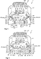
- Fig. 1 shows a view of a lamp 1 according to the invention.
- the lamp 1 has an elongated U-shaped support profile 2 and an elongated U-shaped device carrier 3, which is fixed to the support profile 2 in a form-fitting manner.
- the equipment carrier 3 closes the support profile 2 transversely to the longitudinal direction 4 with a profile locking base 5, so that a profile interior 6 is formed in the support profile 2.
- the luminaire 1 also has an elongated optics cover 7, which is fixed to the device carrier 3.
- the optics cover 7 has a plurality of prisms 8a formed integrally in the optics cover 7 and can be produced in an extrusion process.
- the optics cover 7 closes the device carrier 3 transversely to the longitudinal direction 4, so that a carrier interior 9 is formed in the device carrier 3.
- the device carrier 3 has a luminous support base 10, which is arranged parallel to and at a distance from the profile locking base 5 and extends in the longitudinal direction 4.
- the light support base 10 divides the support interior 9 into a light interior 9a and a heat insulating space 9b.
- a light support plate 11 with a plurality of light sources 12 is fixed on the light support base 10 on both sides by a retaining clip 13 in each case.
- a seal 14 is arranged on both sides, which is supported on the optics cover 7 and on the device carrier 3 and seals the luminous interior 9a from the outside.
- the support profile 2 has a current guide rail 15 with several electrical conductors 15a, which supply the several light sources 12 on the luminous support plate 11 with current.
- an electrical connection element - not visible here - is provided on the luminous support plate 11, by means of which the multiple light sources 12 on the luminous support plate 11 are electrically conductively connected to the conductors 15a of the power supply rail 15 via a control device 16.
- the control device 16 can control the multiple light sources 12 individually or in groups.
- the control device 16 is arranged in the profile interior 6 and is supported on the profile locking base 5.
- the profile interior is through the heat insulating space 9b 6 with the control device 16 from the luminous interior 9a with the luminous support plate 11 is thermally insulated.
- the device carrier 3 is a shaped sheet metal part and the profile locking base 5 is integrally formed by two lateral projections 17a on the luminous support base 10 of the device carrier 3.
- the projections 17a face one another and extend in the longitudinal direction 4 over an entire length of the device carrier 3.
- the equipment rack 3 is clamped in the support profile 2 on both sides.
- flanges 18 of the device carrier 3 are arranged in the profile interior 6 and clamped between flanges 19 of the support profile 2 in the longitudinal direction 4 over an entire length of the support profile 2 or the device carrier 3.
- a clamping arrangement 20 with a clamping spring 20a and a clamping groove 20b is integrally formed on both sides.
- the clamping spring 20a and the clamping groove 20b engage one another and extend in the longitudinal direction 4.
- the support profile 2 is supported on the equipment carrier 3 on both sides on a respective support formation 21.
- the device carrier 3 has a handle groove arrangement 22 on both sides with a plurality of preferably parallel handle grooves 23.
- the respective grip groove arrangement 22 extends on the outside on the respective flange 18 of the device carrier 3 in the longitudinal direction 4.
- the luminous support plate 11 with the light sources 12 is arranged in the luminous interior 9a in contact with the luminous support base 10 and is pressed against the latter on both sides by the retaining clips 13.
- the light support plate 11 rests on the light support base 10 and the heat generated in the light support plate 11 by the light sources 12 can be dissipated to the outside through the device carrier 3.
- the luminous support base 10 is separated from the control device 16 by the heat insulating space 9b, so that a direct heat transfer between the luminous support plate 11 and the control device 16 is advantageously prevented.
- a guide formation 24 aligned in the luminous interior 9a is integrally formed, which centers the luminous support plate 11 in the luminous interior 9a transversely to the longitudinal direction 4.
- the respective retaining clip 13 has a first support wing 25a and a second support wing 25b, which are connected to one another by a support edge 26.
- the respective retaining clip 13 is supported with the first support wing 25a on the luminous support plate 11, with the second support wing 25b on the optics cover 7 and with the support edge 26 on an elongated support contour 27 of the device carrier 3.
- the respective retaining clip 13 is resilient and presses the luminous support plate 11 against the luminous support base 10 through the first support wing 25a and the optics cover 7 against the luminous support plate 11 through the second support wing 25b. In this way, the luminous support plate 11 is fixed on the luminous support base 10 and the optics cover 7 on the luminous support plate 11.
- the optics cover 7 is pressed against the luminous support plate 11 by the seal 14, which is supported on one side on the device carrier 3 and on the other side on the optics cover 7.
- the retaining clip 13 is fixed to the support contour 27 of the device carrier 3 in the longitudinal direction 4 by a plurality of tips 28 formed integrally on the support edge 26.
- the optics cover 7 encloses the light sources 12 fixed on the luminous support plate 11 transversely to the longitudinal direction 4 and the light sources 12 are thereby protected from contamination.
- the luminous interior 9a is also sealed off from the outside by the seal 14.
- the seal 14 can, for example, be elastic and injection-molded onto the optics cover 7.
- the lamp can 1 by cover caps - not shown here - be sealed on both sides in the longitudinal direction to the outside.
- Fig. 2 shows a view of the lamp 1 according to the invention in a different embodiment.
- the equipment rack 3 has a structure that differs from the equipment rack 3 in FIG Fig. 1 on. Otherwise, the structure of the lamp 1 shown here corresponds to the structure of the in Fig. 1 shown lamp 1.
- the equipment carrier 3 is an extruded part formed from aluminum in an extrusion process.
- the profile locking base 5 is integrally formed by two T-shaped projections 17b facing the support profile 2 on the luminous support base 10 of the device carrier 3.
- the device carrier 3 has, in contrast to the one shown in FIG Fig. 1
- the device carrier 3 shown has an intermediate flange 18a which divides the light interior 9a in the longitudinal direction 4 and is closed by two optics covers 7 arranged next to one another.
- the respective optics cover 7 is fixed on one side between the flange 18 and the intermediate flange 18a of the device carrier 3.
- the intermediate flange 18a has an inner contour of the facing flange 18 on both sides.
- the device carrier 3 is shaped in such a way that the respective optics cover 7, the support profile 2 and other components of the lamp 1 according to the invention remain the same.
- the equipment rack 3 shown here and the one in FIG Fig. 1 Device carrier 3 shown in the lamp 1 according to the invention can be interchanged with one another.
- Fig. 3 shows a view of the lamp 1 according to the invention in a different embodiment.
- the optics cover 7 has a structure that differs from the optics cover 7 in FIG Fig. 1 on. Otherwise, the structure of the lamp 1 shown here corresponds to the structure of the in Fig. 1 shown lamp 1.
- the optics cover 7 differs from the optics cover in FIG Fig. 1 a plurality of lenses 8b formed integrally on the optical cover 7.
- the optics cover 7 also has a centering recess 29b of a centering arrangement 29 on one of the lenses 8b, into which a centering recess 29a - here the light source 12 on the luminous support plate 11 - engages and in this way centers the lens 8b on the light source 12 and in and across to the longitudinal direction 4 on the light source 12.
- the thermal expansion of the optics cover 7 is not prevented to the side of the centering recess 29b and distortion of the optics cover 7 is advantageously avoided.
- the optics cover 7 can for example be produced in an injection molding process and consist of several optics cover parts arranged one behind the other in the longitudinal direction 4.
- the optics cover 7 is shaped in such a way that the support profile 2, the device carrier 3 and other components of the lamp 1 according to the invention remain the same.
- the optical cover 7 shown here and the one in FIG FIGS. 1 and 2 Optical covers 7 shown in the lamp 1 according to the invention are interchangeable with one another.
- Fig. 4 shows a view of the lamp 1 according to the invention in a different embodiment.
- the optics cover 7 has a structure that differs from the optics cover 7 in FIG Fig. 2 on. Otherwise, the structure of the lamp 1 shown here corresponds to the structure of the in Fig. 2 1.
- the device carrier 3 has a structure that differs from the device carrier 3 in FIG Fig. 3 on. Otherwise, the structure of the lamp 1 shown here corresponds to the structure of the in Fig. 3 shown lamp 1.
- the equipment carrier 3 is an extruded part formed from aluminum in an extrusion process.
- the profile locking base 5 is integrally formed by the T-shaped projections 17b facing the support profile 2 on the luminous support base 10 of the device carrier 3.
- the device carrier 3 also has different from that in Fig. 3
- the device carrier 3 shown has the intermediate flange 18a which divides the luminous interior 9a in the longitudinal direction 4.
- the respective optics cover 7 with the lenses 8b is fixed on one side between the flange 18 and the intermediate flange 18a of the device carrier 3.
- the device carrier 3 is shaped in such a way that the respective optics cover 7, the support profile 2 and other components of the lamp 1 according to the invention remain the same.
- the equipment rack 3 shown here and the one in FIG Fig. 3 Device carrier 3 shown in the lamp 1 according to the invention can be interchanged with one another.
- the optics cover 7 shown has a plurality of lenses 8b formed integrally on the optics cover 7.
- the optics cover 7 also has the centering recess 29b of the centering arrangement 29 on one of the lenses 8b, through which the optics cover 7 is centered on the luminous support plate 11.
- the optics cover 7 can for example be produced in an injection molding process and consist of several optics cover parts arranged one behind the other in the longitudinal direction 4.
- the optics cover 7 is shaped in such a way that the support profile 2, the device carrier 3 and other components of the lamp 1 according to the invention remain the same.
- the optical covers 7 shown here and those in FIG Fig. 2 Optical covers 7 shown in the lamp 1 according to the invention are interchangeable with one another.
- FIG. 11 shows a partial view of the device carrier 3 with the retaining clip 13 in a first embodiment, as shown in FIGS. 1 to 4 is shown.
- Fig. 6 is a View of the in Fig. 5 retaining clip 13 shown.
- the retaining clip 13 has the first support wing 25a and the second support wing 25b, which are connected to one another by the support edge 26.
- the respective retaining clip 13 is supported with the first support wing 25a on the luminous support plate 11, with the second support wing 25b on the optics cover 7 and with the support edge 26 on the elongated support contour 27 of the device carrier 3.
- the respective retaining clip 13 presses the luminous support plate 11 against the luminous support base 10 through the first support wing 25a and the optics cover 7 against the luminous support plate 11 through the second support wing 25b. In this way, the luminous support plate 11 is fixed on the luminous support base 10 and the optics cover 7 on the luminous support plate 11. As a result of the plurality of tips 28 formed integrally on the support edge 26, the retaining clip 13 is also fixed to the support contour 27 of the device carrier 3 in the longitudinal direction 4.
- the first support wing 25a has a first beveled bevel region 30 and two second beveled bevel regions 31.
- the folded areas 30 and 31 are folded transversely to the longitudinal direction 4 and extend in the longitudinal direction 4.
- the first folded area 30 presses the luminous support plate 11 towards the luminous support base 10 and the two second folded regions 31 fix the luminous support plate 11 laterally on the luminous support base 10.
- the folded regions 30 and 31 act transversely to the longitudinal direction 4, so that the luminous support plate 11 is fixed on the luminous support base 10 such that it can be displaced in the longitudinal direction 4.
- a thermal expansion of the luminous support plate 11 in the longitudinal direction 4 can thereby be compensated and a distortion of the luminous support plate 11 during operation of the luminaire 1 can advantageously be prevented.
- the second support wing 25b of the retaining clip 13 has a third beveled bevel region 32 which is beveled transversely to the longitudinal direction 5 and extends in the longitudinal direction 4.
- the third edging region 32 presses the optics cover 7 to form the luminous support plate 11 and lies against a support surface 33 of the optics cover 7 that extends in the longitudinal direction 4.
- FIG. 11 shows a partial view of the device carrier 3 with the retaining clip 13 in a second embodiment, as shown in FIGS. 1 to 4 is shown.
- Fig. 8 is a view of the in Fig. 7 retaining clip 13 shown.
- the second folded regions 31 of the first support wing 25a of the retaining clip 13 are different from the second folded regions 31 in FIG FIGS. 5 and 6 shown retaining clip configured.
- the structure of the retaining clip 13 here corresponds to the structure of the retaining clip 13 in the first embodiment.
- FIG. 11 shows a view of the device carrier 3 like this one in FIG Fig. 1 and Fig. 3 is shown.
- the device carrier 3 is here a shaped sheet metal part made of sheet steel.
- Fig. 10 shows a view of the device carrier 3, which differs from the device carrier 3 from Fig. 9 is an extrusion made of aluminum.
- the profile locking base 5 is formed by T-shaped projections 17b, otherwise the device carrier 3 shown here corresponds to that in FIG Fig. 9 Device carrier 3 shown. Both device carriers 3 are interchangeable in the light 1.
- FIG. 11 shows a view of the device carrier 3 like this one in FIG Fig.
- the device carrier 3 is here an extruded part made of aluminum.
- the light interior 9a is divided by the intermediate flange 18a and two optical covers 7 with prisms 8a or with lenses 8b can be fixed on the device carrier 3.
- the profile locking base 5 is formed by T-shaped projections 17b.
- the equipment rack 3 shown here corresponds to the equipment racks 3 from Figures 9 and 10 so that they can be interchanged in the lamp 1.
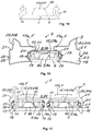
- Fig. 12 shows a view of the optics cover 7 with the prisms 8a.
- Fig. 12 and in Fig. 13 are views of the in Fig. 12 shown optics cover 7 is shown, which is built into the differently configured equipment carrier 3.
- the optical cover 7 shown here can for example be produced in an extrusion process and the prisms 8a can be coextruded.
- the seal 14 is injection-molded onto the optics cover 7 and seals the interior 9a of the light to the outside and additionally presses the optics cover 7 onto the light support base 10.
- the optics cover 7 with the prisms 8a is built into the variously configured equipment mounts 3.
- the device carrier 3 corresponds to that in Fig. 1 , Fig.
- Fig. 9 shown equipment carrier 3 and is a sheet metal part made of sheet steel.
- the device carrier 3 corresponds to that in Fig. 2 , Fig. 4 or Fig. 11 shown device carrier 3 and is an extruded part made of aluminum.
- Fig. 15 shows a view of the optics cover 7 with the lenses 8b.
- Fig. 16 and in Fig. 17 are views of the in Fig. 15 shown optics cover 7 is shown, which is built into the differently configured equipment carrier 3.
- the optics cover 7 shown here can for example be produced in an injection molding process and consist of several optics cover parts.
- the seal 14 is injection-molded onto the optics cover 7 and seals the interior 9a of the light to the outside and additionally presses the optics cover 7 onto the light support base 10.
- the optics cover 7 with the lenses 8b is built into the variously configured equipment mounts 3.
- the device carrier 3 corresponds to that in Fig. 1 , Fig. 3 or Fig. 9 shown equipment carrier 3 and is a sheet metal part made of sheet steel.
- the device carrier 3 corresponds to that in Fig. 2 , Fig. 4 or Fig. 11 shown device carrier 3 and is an extruded part made of aluminum.
- the heat insulating space 9b prevents a direct heat transfer between the luminous support plate 11 and the control device 16, whereby the functionality of the luminaire 1 is advantageously preserved.
- the retaining clip 13 eliminates the need for additional fasteners and the assembly of the lamp 1 is significantly simplified.
- the seal 14 advantageously seals the light interior 9a to the outside and additionally supports the optics cover 7 in the device carrier 3.
- the centering arrangement 29 on the optics cover 7 enables the lenses 8b to be centered on the light sources 12 and does not prevent the optics cover 7 from thermal expansion. In particular, a distortion of the luminous support plate 11 can thereby be prevented and optical losses in the luminaire 1 can advantageously be reduced.
Description
Die Erfindung betrifft eine geradlinige und sich in Längsrichtung erstreckende Leuchte für ein Lichtband gemäß dem Oberbegriff des Anspruchs 1.The invention relates to a straight and longitudinally extending luminaire for a light strip according to the preamble of claim 1.
Aus dem Stand der Technik sind Leuchten für ein Lichtband bereits bekannt. Das Lichtband umfasst üblicherweise mehrere geradlinige Leuchten, die in einer Reihe an einer Wand oder an einer Decke montiert sind. Die jeweilige Leuchte umfasst dabei üblicherweise ein Tragprofil mit einer Stromführungsschiene, an dem ein Geräteträger mit einer Lichtquellenplatte festgelegt ist. Die Lichtquellenplatte mit mehreren Lichtquellen wird über die Stromführungsschiene mit Strom versorgt und durch ein Steuergerät in dem Tragprofil gesteuert. Der Geräteträger ist üblicherweise mit einer Optikabdeckung geschlossen, über die das durch die Lichtquellen erzeugte Licht gestreut wird. In der Leuchte müssen viele Bauteile zusammengebaut werden, wodurch die Montage erschwert und die Herstellungskosten erhöht werden. In
Die Aufgabe der Erfindung ist es, für die Leuchte der gattungsgemäßen Art eine verbesserte oder zumindest alternative Ausführungsform anzugeben, bei der die beschriebenen Nachteile überwunden werden.The object of the invention is to provide an improved or at least alternative embodiment for the luminaire of the generic type in which the disadvantages described are overcome.
Diese Aufgabe wird erfindungsgemäß durch den Gegenstand des unabhängigen Anspruchs 1 gelöst. Vorteilhafte Ausführungsformen sind Gegenstand der abhängigen Ansprüche.According to the invention, this object is achieved by the subject matter of independent claim 1. Advantageous embodiments are the subject of the dependent claims.
Die vorliegende Erfindung beruht auf dem allgemeinen Gedanken, einzelne Bauteile in einer Leuchte zusammen zu montieren und dadurch die Montage der Leuchte zu vereinfachen. Die geradlinige und sich in Längsrichtung erstreckende Leuchte ist für ein Lichtband vorgesehen und weist ein längliches u-förmiges Tragprofil und einen länglichen u-förmigen Geräteträger auf, der an dem Tragprofil formschlüssig festgelegt ist. Der Geräteträger schließt dabei das Tragprofil quer zur Längsrichtung zumindest bereichsweise mit einem Profilschließboden und dadurch ist ein Profilinnenraum in dem Tragprofil gebildet. Die Leuchte weist ferner wenigstens eine längliche Optikabdeckung auf, die an dem Geräteträger festgelegt ist. Die wenigstens eine Optikabdeckung schließt den Geräteträger quer zur Längsrichtung und dadurch ist ein Trägerinnenraum in dem Geräteträger gebildet. Die Leuchte weist auch wenigstens eine längliche Leuchttragplatte mit mehreren Lichtquellen auf, die in dem Trägerinnenraum des Geräteträgers festgelegt ist. Dabei weist die Leuchte wenigstens zwei längliche V-förmige Halteklammern mit jeweils einem ersten Abstützflügel und mit einem zweiten Abstützflügel auf, die jeweils durch eine Abstützkante miteinander verbunden sind. Die jeweilige Halteklammer stützt sich erfindungsgemäß in dem Trägerinnenraum mit dem ersten Abstützflügel an der Leuchttragplatte, mit dem zweiten Abstützflügel an der wenigstens einen Optikabdeckung und mit der Abstützkante an einer länglichen Stützkontur des Geräteträgers ab. Die Leuchttragplatte und die wenigstens eine Optikabdeckung sind zudem in dem Trägerinnenraum zu dem Tragprofil hin an dem Geräteträger festgelegt, so dass die Haltewirkung der Halteklammer durch das Gewicht der Leuchttragplatte und durch das Gewicht der Optikabdeckung verstärkt werden kann.The present invention is based on the general idea of assembling individual components in a luminaire and thereby simplifying the assembly of the luminaire. The straight and longitudinally extending lamp is intended for a light band and has an elongated U-shaped support profile and an elongated U-shaped device carrier which is positively fixed to the support profile. The device carrier closes the support profile transversely to the longitudinal direction at least in some areas with a profile locking base and a profile interior is thereby formed in the support profile. The luminaire also has at least one elongated optics cover that is attached to the device carrier. The at least one optics cover closes the device carrier transversely to the longitudinal direction and a carrier interior is thereby formed in the device carrier. The lamp also has at least one elongated light support plate with several light sources, which is fixed in the carrier interior of the device carrier. The lamp has at least two elongated V-shaped retaining clips, each with a first support wing and a second support wing, which are each connected to one another by a support edge. According to the invention, the respective retaining clip is supported in the carrier interior with the first support wing on the luminous support plate, with the second support wing on the at least one optics cover and with the support edge on an elongated support contour of the device carrier. The luminous support plate and the at least one optics cover are also fixed in the carrier interior towards the support profile on the device carrier so that the holding effect of the retaining clip can be reinforced by the weight of the luminous support plate and the weight of the optics cover.
Bei der betriebsgerechten Ausrichtung der Leuchte kann in der erfindungsgemäßen Leuchte die Haltewirkung der Halteklammer durch das Gewicht der Leuchttragplatte und durch das Gewicht der Optikabdeckung verstärkt werden. Insbesondere ist dann die Gewichtskraft von der Leuchttragplatte und von der Optikabdeckung zu der länglichen Stützkontur des Geräteträgers gerichtet, so dass dadurch die Halteklammer an die Stützkontur verstärkt abgestützt ist. Insbesondere kann die erfindungsgemäße Halteklammer dadurch für eine sichere nachhaltige Befestigung der Leuchttragplatte und der Optikabdeckung in dem Trägerinnenraum sorgen. Ferner kann dadurch eine Demontage der Optikabdeckung erschwert werden, da beim Lösen der Optikabdeckung von dem Geräteträger die Halteklammer an die Stützkontur verstärkt gestützt wird und das Lösen der Optikabdeckung verhindert werden kann.
Zweckgemäß kann das Tragprofil eine Stromführungsschiene mit mehreren elektrischen Leitern aufweisen, die die mehreren Lichtquellen auf der Leuchttragplatte mit Strom versorgen können. Dazu kann an der Leuchttragplatte ein elektrisches Anschlusselement vorgesehen sein, durch das die mehreren Lichtquellen auf der Leuchttragplatte mit der Stromführungsschiene verbindbar sind. Dazu kann das elektrische Anschlusselement in die Stromführungsschiene eingreifen und auf diese Weise die mehreren Lichtquellen mit wenigstens einem der Leiter der Stromführungsschiene elektrisch verbinden. Das Anschlusselement kann ferner mit einem Steuergerät elektrisch verbunden sein, das die mehreren Lichtquellen einzeln oder in Gruppen ansteuern kann. Zweckgemäß sind die mehreren Lichtquellen an einer Vorderseite der Leuchttragplatte angeordnet, die der Optikabdeckung zugewandt in dem Trägerinnenraum angeordnet ist. Das elektrische Anschlusselement kann dann zweckgemäß an einer der Vorderseite abgewandten Rückseite der Leuchttragplatte und dadurch dem Profilinnenraum zugewandt festgelegt sein.When the lamp is properly aligned for operation, the holding effect of the retaining clip in the lamp according to the invention can be reinforced by the weight of the light support plate and by the weight of the optics cover. In particular, the weight force is then from the luminous support plate and from the optics cover directed towards the elongated support contour of the device carrier, so that the retaining clip is reinforced on the support contour as a result. In particular, the retaining clip according to the invention can thereby be used for secure, sustainable fastening of the luminous support plate and the optical cover in the interior of the support to care. Furthermore, dismantling of the optics cover can be made more difficult because when the optics cover is detached from the device carrier, the retaining clip is reinforced on the support contour and detachment of the optics cover can be prevented.
Appropriately, the support profile can have a current guide rail with several electrical conductors, which can supply the several light sources on the luminous support plate with power. For this purpose, an electrical connection element can be provided on the luminous support plate, by means of which the multiple light sources on the luminous support plate can be connected to the power supply rail. For this purpose, the electrical connection element can engage in the power supply rail and in this way electrically connect the multiple light sources to at least one of the conductors of the power supply rail. The connection element can also be electrically connected to a control device that can control the multiple light sources individually or in groups. Appropriately, the plurality of light sources are arranged on a front side of the luminous support plate, which is arranged facing the optics cover in the carrier interior. The electrical connection element can then appropriately be fixed on a rear side of the luminous support plate facing away from the front side and thereby facing the profile interior.
In der erfindungsgemäßen Leuchte ist der Geräteträger mit wenigstens einer Optikabdeckung geschlossen. Die wenigstens eine Optikabdeckung ist dabei zweckgemäß zumindest bereichsweise und zumindest teilweise lichttransparent ausgestaltet. Die Leuchte kann beispielweise eine einzelne Optikabdeckung aufweisen, die den Geräteträger quer zur Längsrichtung schließt. Alternativ können auch mehrere - und bevorzugt zwei - Optikabdeckungen vorgesehen sein, die quer zur Längsrichtung nebeneinander angeordnet sind und den Geräteträger quer zur Längsrichtung schließen. Dabei kann der Trägerinnenraum in Längsrichtung durch wenigstens einen Zwischenflansch des Geräteträgers aufgeteilt sein und die jeweilige Optikabdeckung kann dann einseitig zwischen einem Flansch des Geräteträgers und dem jeweiligen dem Flansch benachbarten Zwischenflansch oder alternativ zwischen zwei benachbarten Zwischenflanschen festgelegt sein. Der jeweilige Zwischenflansch kann zweckgemäß beidseitig jeweils die Innenkontur des zugewandten Flansches aufweisen, so dass die Optikabdeckung an diesen festlegbar ist. Entsprechend können auch der Abstand der Flansche in einem Geräteträger ohne einen Zwischenflansch und der Abstand der Flansche zu dem jeweiligen Zwischenflansch und der Zwischenflansche zueinander in einem Geräteträger mit dem jeweiligen Zwischenflansch gleich sein. Vorteilhafterweise können dann die Optikabdeckung, die Leuchttragplatte sowie weitere in dem Geräteträger angeordnete Bauteile bei einem Geräteträger mit und ohne den wenigstens einen Zwischenflansch gleich ausgestaltet bleiben.In the lamp according to the invention, the device carrier is closed with at least one optical cover. The at least one optical cover is expediently designed to be at least partially and at least partially light-transparent. The luminaire can, for example, have a single lens cover that closes the device carrier transversely to the longitudinal direction. Alternatively, several - and preferably two - optical covers can also be provided, which are arranged next to one another transversely to the longitudinal direction and close the device carrier transversely to the longitudinal direction. The carrier interior can be divided in the longitudinal direction by at least one intermediate flange of the device carrier and the respective optics cover can then be fixed on one side between a flange of the device carrier and the respective intermediate flange adjacent to the flange, or alternatively between two adjacent intermediate flanges. The respective intermediate flange can expediently have the inner contour of the facing flange on both sides, so that the optics cover can be fixed to it. Correspondingly, the distance between the flanges in an equipment rack without an intermediate flange and the distance between the flanges and the respective intermediate flange and the intermediate flanges from one another in an equipment rack with the respective intermediate flange can be the same. Advantageously, the optics cover, the luminous support plate as well as further components arranged in the device carrier can then remain configured in the same way in a device carrier with and without the at least one intermediate flange.
Durch die jeweiligen Halteklammer werden vorteilhafterweise die Leuchttragplatte und die Optikabdeckung zusammen in dem Trägerinnenraum festgelegt und zusätzliche Befestigungsmittel entfallen. Dadurch können sowohl die Herstellungskosten reduziert als auch die Montage der Leuchte vereinfacht werden. Die Halteklammer kann vorteilhafterweise auch für eine sichere nachhaltige Befestigung der Leuchttragplatte und der Optikabdeckung in dem Trägerinnenraum sorgen. Zudem ist durch die erfindungsgemäße Halteklammer eine Demontage der Optikabdeckung erschwert, so dass die Verletzungsgefahr einer nicht zuständigen Person reduziert wird.By means of the respective retaining clips, the luminous support plate and the optics cover are advantageously fixed together in the interior of the support and additional fastening means are dispensed with. This allows both the production costs to be reduced and the assembly of the lamp to be simplified. The retaining clip can advantageously also ensure that the luminous support plate and the optics cover are securely and sustainably fastened in the interior of the support. In addition, the retaining clip according to the invention makes dismantling of the optics cover more difficult, so that the risk of injury to a person who is not responsible is reduced.
Vorteilhafterweise kann vorgesehen sein, dass die jeweilige Halteklammer durch den ersten Abstützflügel die Leuchttragplatte in dem Trägerinnenraum an den Geräteträger zu dem Tragprofil hin anpresst. Dadurch liegt die Leuchttragplatte an dem Geräteträger an und die in der Leuchttragplatte erzeugte Wärme kann an den Geräteträger abgeleitet werden. Zusätzlich presst die jeweilige Halteklammer durch den zweiten Abstützflügel die wenigstens eine Optikabdeckung in dem Trägerinnenraum an die Leuchttragplatte zu dem Tragprofil hin an. Auf diese Weise sind die Leuchttragplatte an dem Geräteträger und die Optikabdeckung an der Leuchttragplatte zu dem Tragprofil hin angepresst. Die Optikabdeckung umschließt dadurch die an der Leuchttragplatte festgelegten Lichtquellen quer zur Längsrichtung und die Lichtquellen an der Leuchttragplatte können dadurch besser von Verunreinigungen geschützt werden.Advantageously, it can be provided that the respective retaining clip presses the luminous support plate in the carrier interior onto the device carrier towards the carrier profile through the first support wing. As a result, the light support plate rests against the device carrier and the heat generated in the light support plate can be dissipated to the device carrier. In addition, the respective retaining clip presses the at least one optics cover into the through the second support wing Carrier interior to the light support plate to the support profile. In this way, the luminous support plate is pressed against the device carrier and the optics cover on the luminous support plate is pressed towards the support profile. The optics cover thereby encloses the light sources fixed on the light support plate transversely to the longitudinal direction and the light sources on the light support plate can thereby be better protected from contamination.
Des Weiteren kann vorteilhafterweise vorgesehen sein, dass der erste Abstützflügel der jeweiligen Halteklammer wenigstens einen ersten abgekanteten Abkantbereich und wenigstens einen zweiten abgekanteten Abkantbereich aufweist. Die jeweiligen Abkantbereiche sind quer zur Längsrichtung abgekantet und erstrecken sich in Längsrichtung. Dabei kann der wenigstens eine erste Abkantbereich die Leuchttragplatte zu dem Tragprofil hin an den Geräteträger und der wenigstens eine zweite Abkantbereich die Leuchttragplatte parallel zu dem Tragprofil und quer zur Längsrichtung seitlich festlegen. Der wenigstens eine erste Abkantbereich und der wenigstens eine zweite Abkantbereich wirken dabei beide quer zur Längsrichtung, so dass die Leuchttragplatte in Längsrichtung verschiebbar an dem Geräteträger festgelegt ist. Insbesondere können dadurch eine Wärmeausdehnung der Leuchttragplatte in und quer zur Längsrichtung kompensiert und eine Verzerrung der Leuchttragplatte im Betrieb der Leuchte vorteilhaft verhindert werden.Furthermore, it can advantageously be provided that the first support wing of the respective retaining clip has at least one first beveled bevel area and at least one second beveled bevel area. The respective folding areas are folded transversely to the longitudinal direction and extend in the longitudinal direction. The at least one first folded area can fix the luminous support plate towards the supporting profile on the device carrier and the at least one second folded zone can fix the luminous supporting plate parallel to the supporting profile and laterally transversely to the longitudinal direction. The at least one first folding area and the at least one second folding area both act transversely to the longitudinal direction, so that the luminous support plate is fixed on the device carrier such that it can be displaced in the longitudinal direction. In particular, thermal expansion of the luminous support plate in and across the longitudinal direction can thereby be compensated for and distortion of the luminous support plate during operation of the lamp can advantageously be prevented.
In dem Trägerinnenraum kann an der Leuchttragplatte beidseitig jeweils eine Halteklammer angeordnet sein, so dass durch die Abkantbereiche des ersten Abstützflügels der jeweiligen Halteklammern die Leuchttragplatte an dem Geräteträger anliegend und quer zur Längsrichtung verschiebefest festgelegt ist. Die jeweiligen zweiten Abkantbereiche des ersten Abstützflügels der jeweiligen Halteklammern verhindern dabei keine Wärmeausdehnung der Leuchttragplatte quer zur Längsrichtung, so dass eine Verzerrung der Leuchttragplatte im Betrieb der Leuchte vorteilhaft verhindert werden kann.In the interior of the support, a retaining clip can be arranged on both sides of the light support plate, so that the light support plate lies against the device carrier and is fixed transversely to the longitudinal direction through the folding areas of the first support wing of the respective retaining clips. The respective second folded areas of the first support wing of the respective retaining clips do not prevent any thermal expansion of the luminous support plate transversely to the longitudinal direction, so that a distortion of the light support plate during operation of the lamp can advantageously be prevented.
Vorteilhafterweise kann auch vorgesehen sein, dass der zweite Abstützflügel der jeweiligen Halteklammer wenigstens einen dritten abgekanteten Abkantbereich aufweist, der quer zur Längsrichtung abgekantet ist und sich in Längsrichtung erstreckt. Der dritte Abkantbereich legt dabei die wenigstens eine Optikabdeckung zu der Leuchttragplatte hin fest. Der dritte Abkantbereich des zweiten Abstützflügels der jeweiligen Halteklammer kann dabei an einer in Längsrichtung erstreckenden Stützfläche der Optikabdeckung anliegen, um einen großflächigen Kontakt des zweiten Abstützflügels mit der Optikabdeckung zu ermöglichen.Advantageously, it can also be provided that the second support wing of the respective retaining clip has at least one third beveled bevel region which is beveled transversely to the longitudinal direction and extends in the longitudinal direction. The third folding area defines the at least one optical cover towards the luminous support plate. The third folded area of the second support wing of the respective retaining clip can bear against a support surface of the optics cover that extends in the longitudinal direction in order to enable a large-area contact of the second support wing with the optics cover.
Um die jeweilige Halteklammer in dem Geräteträger in Längsrichtung verschiebefest festzulegen, können an der Abstützkante der jeweiligen Halteklammer mehrere Spitzen integral ausgeformt sein. Die Spitzen legen dabei die Halteklammer in Längsrichtung an der jeweiligen Stützkontur des Geräteträgers fest.In order to fix the respective retaining clip so that it cannot be displaced in the device carrier in the longitudinal direction, a plurality of tips can be integrally formed on the supporting edge of the respective retaining clip. The tips fix the retaining clip in the longitudinal direction on the respective support contour of the device carrier.
Bei einer vorteilhaften Weiterbildung der erfindungsgemäßen Leuchte ist vorgesehen, dass zwischen der wenigstens einen Optikabdeckung und dem Geräteträger eine sich in Längsrichtung erstreckende Dichtung angeordnet ist. Die Dichtung stützt sich dabei einseitig an dem Geräteträger und andersseitig an der wenigstens einen Optikabdeckung ab und legt die wenigstens eine Optikabdeckung zu dem Tragprofil hin in dem Trägerinnenraum fest.In an advantageous further development of the lamp according to the invention it is provided that a seal extending in the longitudinal direction is arranged between the at least one optics cover and the device carrier. The seal is supported on one side on the device carrier and on the other side on the at least one optical system cover and fixes the at least one optical system cover to the support profile in the carrier interior.
Vorteilhafterweise kann die Dichtung die Leuchttragplatte an den Geräteträger zu dem Tragprofil hin anpressen. Insbesondere kann dadurch die Optikabdeckung an dem Geräteträger sicher festgelegt und ein unerwünschtes Lösen der Optikabdeckung von dem Geräteträger verhindert werden. Die Dichtung kann beispielsweise elastisch sein, um eine Verformung der Optikabdeckung oder des Geräteträgers infolge einer Wärmeausdehnung im Betrieb der Leuchte zu kompensieren. Vorteilhafterweise kann die Dichtung an die wenigstens eine Optikabdeckung angespritzt sein, um die Herstellungskosten zu reduzieren.Advantageously, the seal can press the luminous support plate onto the device carrier towards the support profile. In particular, this allows the optics cover to be securely attached to the device carrier and an undesired detachment of the optics cover from the device carrier can be prevented. The seal can be elastic, for example, to prevent deformation of the optics cover or the To compensate device carrier due to thermal expansion during operation of the luminaire. The seal can advantageously be injection-molded onto the at least one optics cover in order to reduce the manufacturing costs.
Bei einer vorteilhaften Weiterbildung der erfindungsgemäßen Leuchte ist vorgesehen, dass der Geräteträger einen Leuchttragboden aufweist, der parallel und beabstandet zu dem Profilschließboden angeordnet ist und sich in Längsrichtung erstreckt. Der Leuchttragboden teilt den Trägerinnenraum in einen Leuchtinnenraum mit der wenigstens einen Leuchttragplatte und einen Wärmeisolierraum auf, der in Längsrichtung zwischen dem Profilinnenraum und dem Leuchtinnenraum angeordnet ist. Die Leuchttragplatte mit den mehreren Lichtquellen ist dann in dem Leuchtinnenraum an dem Leuchttragboden anliegend angeordnet und kann durch die jeweiligen Halteklammern an diesen festgelegt - beispielweise angepresst - sein.In an advantageous development of the lamp according to the invention, it is provided that the device carrier has a light support base which is arranged parallel to and spaced apart from the profile locking base and extends in the longitudinal direction. The light support base divides the support interior into a light interior with the at least one light support plate and a heat insulating space which is arranged in the longitudinal direction between the profile interior and the light interior. The luminous support plate with the multiple light sources is then arranged in the luminous interior adjacent to the luminous support base and can be fixed - for example pressed on - to the latter by the respective retaining clips.
Der Wärmeisolierraum ist zwischen dem Leuchtinnenraum und dem Profilinnenraum angeordnet und isoliert den Profilinnenraum und den Leuchtinnenraum voneinander. Dadurch kann insbesondere die direkte Wärmeübertragung zwischen der Leuchttragplatte mit den mehreren Lichtquellen und elektrischen oder elektronischen Bauteilen in dem Profilinnenraum - wie beispielweise einem Steuergerät - minimiert werden. Auf diese Weise kann die in der Leuchte erzeugte Wärme bevorzugt nach außen abgeleitet und die Funktionalität der Leuchte vorteilhaft erhalten werden.The heat insulating space is arranged between the light interior and the profile interior and isolates the profile interior and the light interior from one another. In this way, in particular, the direct heat transfer between the luminous support plate with the multiple light sources and electrical or electronic components in the profile interior - such as a control device, for example - can be minimized. In this way, the heat generated in the luminaire can preferably be dissipated to the outside and the functionality of the luminaire can advantageously be retained.
Vorteilhafterweise kann vorgesehen sein, dass der Profilschließboden durch wenigstens einen dem Tragprofil zugewandten Vorsprung an dem Leuchttragboden des Geräteträgers integral ausgebildet ist, wobei der Vorsprung quer zur Längsrichtung einen T-förmigen Querschnitt aufweist und sich in Längsrichtung erstreckt. Alternativ kann der Profilschließboden durch zwei seitliche Vorsprünge an dem Leuchttragboden des Geräteträgers integral ausgebildet sein, wobei die Vorsprünge einander zugewandt sind und sich in Längsrichtung erstrecken. An den jeweiligen Vorsprüngen kann sowohl das Tragprofil als auch elektrische oder elektronische Bauteile in dem Profilinnenraum - wie beispielsweise ein Steuergerät - abgestützt sein. Der jeweilige Vorsprung erstreckt sich dabei in Längsrichtung zweckgemäß über eine gesamte Länge des Geräteträgers, so dass der Profilinnenraum und der Leuchtinnenraum über eine gesamte Länge der Leuchte voneinander wärmeisolierend getrennt sind.Advantageously, it can be provided that the profile locking base is integrally formed by at least one projection facing the support profile on the luminous support base of the device carrier, the projection having a T-shaped cross section transversely to the longitudinal direction and extending in the longitudinal direction. Alternatively, the profile locking base can be attached by means of two lateral projections be integrally formed with the light support base of the device carrier, the projections facing one another and extending in the longitudinal direction. Both the support profile and electrical or electronic components in the profile interior - such as a control device - can be supported on the respective projections. The respective projection expediently extends in the longitudinal direction over an entire length of the device carrier, so that the profile interior and the light interior are separated from one another in a heat-insulating manner over an entire length of the lamp.
Bei einer Weiterbildung des Geräteträgers ist vorteilhafterweise vorgesehen, dass der Leuchttragboden wenigstens eine Führungsausformung zum Zentrieren der Leuchttragplatte aufweist. Dabei ist die Führungsausformung in den Leuchtinnenraum gerichtet und erstreckt sich in Längsrichtung. Die Führungsausformung erleichtert eine zentrierte Festlegung der Leuchttragplatte mit den mehreren Lichtquellen in dem Leuchtinnenraum, wodurch die Montage der Leuchte vereinfacht wird.In a further development of the device carrier, it is advantageously provided that the light support base has at least one guide formation for centering the light support plate. The guide formation is directed into the light interior and extends in the longitudinal direction. The guide formation facilitates a centered fixing of the light support plate with the multiple light sources in the light interior, whereby the assembly of the light is simplified.
Vorteilhafterweise kann der Geräteträger in dem Tragprofil in Längsrichtung beidseitig eingeklemmt sein. Insbesondere kann dadurch die Montage und die Demontage des Geräteträgers an dem Tragprofil vereinfacht werden. So können beispielsweise Flansche des Geräteträgers in dem Profilinnenraum angeordnet und zwischen Flanschen des Tragprofils in Längsrichtung über eine gesamte Länge des Tragprofils oder des Geräteträgers eingeklemmt sein. Zusätzlich kann beidseitig jeweils eine Klemmanordnung mit einer Klemmnut und einer Klemmfeder vorgesehen sein, die sich in Längsrichtung erstrecken und quer zur Längsrichtung miteinander in Eingriff bringbar sind. Zweckgemäß sind dann die jeweilige Klemmfeder oder Klemmnut außenseitig an den Flanschen des Geräteträgers und die jeweilige Klemmnut oder Klemmfeder innenseitig an den Flanschen des Tragprofils integral ausgeformt. Um die Montage des Geräteträgers an dem Tragprofil zu vereinfachen, kann der Geräteträger beidseitig jeweils eine Griffrillenanordnung mit mehreren sich bevorzugt parallelen Griffrillen aufweist. Die jeweilige Griffrillenanordnung erstreckt sich dabei außenseitig an einem Flansch des Geräteträgers in Längsrichtung.The equipment carrier can advantageously be clamped in the support profile on both sides in the longitudinal direction. In particular, the assembly and disassembly of the device carrier on the support profile can be simplified as a result. For example, flanges of the device carrier can be arranged in the profile interior and clamped between flanges of the support profile in the longitudinal direction over an entire length of the support profile or the device carrier. In addition, a clamping arrangement with a clamping groove and a clamping spring, which extend in the longitudinal direction and can be brought into engagement with one another transversely to the longitudinal direction, can be provided on both sides. Appropriately, the respective clamping spring or clamping groove are then integrally formed on the outside on the flanges of the device carrier and the respective clamping groove or clamping spring on the inside on the flanges of the support profile. To the assembly of the device carrier on the To simplify the support profile, the equipment carrier can have a handle groove arrangement on both sides with a plurality of preferably parallel handle grooves. The respective grip groove arrangement extends on the outside on a flange of the device carrier in the longitudinal direction.
Bei einer vorteilhaften Weiterbildung des Geräteträgers ist vorgesehen, dass der Geräteträger ein in einem Strangpressverfahren aus Aluminium geformtes Strangpressteil ist. Alternativ kann der Geräteträger ein aus Stahlblech geformtes Blechformteil sein.In an advantageous further development of the device carrier, it is provided that the device carrier is an extruded part formed from aluminum in an extrusion process. Alternatively, the equipment carrier can be a shaped sheet metal part formed from sheet steel.
Bei einer vorteilhaften Weiterbildung der erfindungsgemäßen Leuchte ist vorgesehen, dass die wenigstens eine Optikabdeckung an dem Geräteträger durch eine Zentrieranordnung in und quer zur Längsrichtung zentriert und in Längsrichtung ausdehnbar festgelegt ist. Zentrieranordnung kann beispielsweise eine Zentrierausformung und eine Zentrierausnehmung umfassen, die quer zur Längsrichtung miteinander in Eingriff bringbar sind. Die jeweilige Zentrierausnehmung oder Zentrierausformung kann dann an der Optikabdeckung und die jeweilige Zentrierausformung oder Zentrierausnehmung kann beispielsweise an der Leuchttragplatte ausgeformt sein. Durch die Zentrieranordnung kann eine in der Optikabdeckung angeordnete Optik relativ zu den mehreren Lichtquellen der Leuchttragplatte ausgerichtet sein und dadurch optische Verluste in der Leuchte reduziert werden. Die Zentrieranordnung verhindert zudem eine Wärmeausdehnung der Optikabdeckung in Längsrichtung nicht und eine Verzerrung der Optikabdeckung im Betrieb der Leuchte kann vorteilhaft verhindert werden.In an advantageous development of the lamp according to the invention, it is provided that the at least one optics cover is centered on the device carrier by a centering arrangement in and transverse to the longitudinal direction and is fixed so that it can be extended in the longitudinal direction. Centering arrangement can for example comprise a centering formation and a centering recess which can be brought into engagement with one another transversely to the longitudinal direction. The respective centering recess or centering formation can then be formed on the optics cover and the respective centering formation or centering recess can be formed, for example, on the luminous support plate. As a result of the centering arrangement, optics arranged in the optics cover can be aligned relative to the multiple light sources of the light support plate and optical losses in the luminaire can thereby be reduced. The centering arrangement also does not prevent thermal expansion of the optics cover in the longitudinal direction and distortion of the optics cover during operation of the lamp can advantageously be prevented.
Bei einer vorteilhaften Weiterbildung der Optikabdeckung ist vorgesehen, dass die wenigstens eine Optikabdeckung mehrere integral ausgeformte Prismen aufweist. Bevorzugt ist die Optikabdeckung dann in einem Extrusionsverfahren hergestellt. Alternativ kann die wenigstens eine Optikabdeckung mehrere integral ausgeformte Linsen aufweisen. Bevorzugt ist die Optikabdeckung dann in einem Spritzgussverfahren hergestellt. Vorteilhafterweise kann die wenigstens eine Optikabdeckung aus mehreren Optikabdeckteilen bestehen, die an dem Geräteträger in Längsrichtung hintereinander angeordnet sind. Insbesondere kann dadurch die Herstellung einer länglichen Optikabdeckung in einem Spritzgussverfahren vereinfacht werden.In an advantageous development of the optics cover, it is provided that the at least one optics cover has a plurality of integrally formed prisms. The optical cover is then preferably produced in an extrusion process. Alternatively, the at least one optical cover can be several integrally have molded lenses. The optics cover is then preferably produced in an injection molding process. The at least one optics cover can advantageously consist of several optics cover parts which are arranged one behind the other on the device carrier in the longitudinal direction. In particular, the production of an elongated optical cover in an injection molding process can thereby be simplified.
Vorteilhafterweise kann die Optikabdeckung dann eine Zentrieranordnung aufweisen, die in die Linsen integriert ist. So kann eine der Linsen eine Zentrierausnehmung und die Leuchttragplatte eine Zentrierausformung aufweisen, die ineinander greifen und die Linse in und quer zur Längsrichtung an der Leuchttragplatte festlegen. Insbesondere können dann bei einer Wärmeausdehnung der Leuchttragplatte und der Optikabdeckung die Linsen und die Lichtquellen zueinander zentriert bleiben und optische Verluste in der Leuchte werden vorteilhaft reduziert. Alternativ oder zusätzlich kann die Optikabdeckung oder auch die Optikabdeckteile wenigstens eine Kennanordnung ausweisen, die an der Optikabdeckung quer zur Längsrichtung beidseitig integral ausgebildet ist. Die Kennanordnung kann beispielsweise einen Kennvorsprung und eine mit dem Kennvorsprung in Eingriff bringbare Kennausnehmung aufweisen, die eine Fehlmontage der Optikabdeckungen oder auch der Optikabdeckteile in Längsrichtung aneinander verhindert und zudem die Montage der Leuchte vereinfacht.The optics cover can then advantageously have a centering arrangement which is integrated into the lenses. For example, one of the lenses can have a centering recess and the luminous support plate can have a centering formation which interlock and fix the lens on the luminous support plate in and across the longitudinal direction. In particular, in the event of thermal expansion of the light support plate and the optics cover, the lenses and the light sources can then remain centered with respect to one another and optical losses in the luminaire are advantageously reduced. Alternatively or additionally, the optics cover or also the optics cover parts can have at least one identification arrangement which is integrally formed on both sides of the optics cover transversely to the longitudinal direction. The identification arrangement can, for example, have an identification projection and an identification recess which can be brought into engagement with the identification projection, which prevents incorrect installation of the optical covers or the optical cover parts on one another in the longitudinal direction and also simplifies the installation of the lamp.
Zusammenfassend können in der erfindungsgemäßen Leuchte durch die Halteklammer zusätzliche Befestigungsmittel vermieden und dadurch die Montage vereinfacht werden; durch den Wärmeisolierraum die in der Leuchte erzeugte Wärme bevorzugt nach außen abgeleitet und die Funktionalität der Leuchte vorteilhaft erhalten werden; durch die Dichtung der Leuchtinnenraum vor Schmutzpartikeln geschützt und die Optikabdeckung sicher an dem Geräteträger festgelegt werden; und durch die Zentrieranordnung an der Optikabdeckung die Wärmeausdehnung der Optikabdeckung kompensiert und optische Verluste vorteilhaft reduziert werden.In summary, additional fastening means can be avoided in the luminaire according to the invention by the retaining clip and the assembly can thereby be simplified; the heat generated in the luminaire is preferably dissipated to the outside through the heat insulating space and the functionality of the luminaire is advantageously preserved; the interior of the light is protected from dirt particles by the seal and the optics cover is securely attached to the device carrier; and through the centering arrangement on the optics cover Thermal expansion of the optics cover is compensated and optical losses are advantageously reduced.
Weitere wichtige Merkmale und Vorteile der Erfindung ergeben sich aus den Unteransprüchen, aus den Zeichnungen und aus der zugehörigen Figurenbeschreibung anhand der Zeichnungen.Further important features and advantages of the invention emerge from the subclaims, from the drawings and from the associated description of the figures on the basis of the drawings.
Es versteht sich, dass die vorstehend genannten und die nachstehend noch zu erläuternden Merkmale nicht nur in der jeweils angegebenen Kombination, sondern auch in anderen Kombinationen oder in Alleinstellung verwendbar sind, ohne den Rahmen der vorliegenden Erfindung zu verlassen.It goes without saying that the features mentioned above and those yet to be explained below can be used not only in the respectively specified combination, but also in other combinations or on their own, without departing from the scope of the present invention.
Bevorzugte Ausführungsbeispiele der Erfindung sind in den Zeichnungen dargestellt und werden in der nachfolgenden Beschreibung näher erläutert, wobei sich gleiche Bezugszeichen auf gleiche oder ähnliche oder funktional gleiche Komponenten beziehen.Preferred exemplary embodiments of the invention are shown in the drawings and are explained in more detail in the following description, with the same reference symbols relating to the same or similar or functionally identical components.
Es zeigen, jeweils schematisch
- Fig. 1
- eine Ansicht einer erfindungsgemäßen Leuchte mit einer Optikabdeckung mit Prismen;
- Fig. 2
- eine Ansicht einer erfindungsgemäßen Leuchte mit zwei Optikabdeckungen mit Prismen;
- Fig. 3
- eine Ansicht einer erfindungsgemäßen Leuchte mit einer Optikabdeckung mit Linsen;
- Fig. 4
- eine Ansicht einer erfindungsgemäßen Leuchte mit zwei Optikabdeckungen mit Linsen;
- Fig. 5
- eine Ansicht eines Geräteträgers mit einer Halteklammer in einer ersten Ausführungsform;
- Fig. 6
- eine Ansicht der in
Fig. 5 gezeigten Halteklammer; - Fig. 7
- eine Ansicht eines Geräteträgers mit einer Halteklammer in einer zweiten Ausführungsform;
- Fig. 8
- eine Ansicht der in
Fig. 7 gezeigten Halteklammer; - Fig. 9
bis 11 - Ansichten abweichend ausgestalteter Geräteträger;
- Fig. 12
- eine Ansicht einer Optikabdeckung mit Prismen und mit einer Dichtung;
- Fig. 13
und 14 - Ansichten der in
Fig. 12 gezeigten Optikabdeckung in unterschiedlich ausgestalteten Geräteträgern; - Fig. 15
- eine Ansicht einer Optikabdeckung mit Linsen und mit einer Dichtung;
- Fig. 16 und 17
- Ansichten der in
Fig. 15 gezeigten Optikabdeckung in unterschiedlich ausgestalteten Geräteträgern.
- Fig. 1
- a view of a lamp according to the invention with an optics cover with prisms;
- Fig. 2
- a view of a lamp according to the invention with two optical covers with prisms;
- Fig. 3
- a view of a lamp according to the invention with an optics cover with lenses;
- Fig. 4
- a view of a lamp according to the invention with two optics covers with lenses;
- Fig. 5
- a view of a device carrier with a retaining clip in a first embodiment;
- Fig. 6
- a view of the in
Fig. 5 retaining clip shown; - Fig. 7
- a view of a device carrier with a retaining clip in a second embodiment;
- Fig. 8
- a view of the in
Fig. 7 retaining clip shown; - Figures 9 to 11
- Views of device carriers designed differently;
- Fig. 12
- a view of an optical cover with prisms and with a seal;
- Figures 13 and 14
- Views of the in
Fig. 12 optical cover shown in differently configured equipment carriers; - Fig. 15
- a view of an optics cover with lenses and with a seal;
- Figures 16 and 17
- Views of the in
Fig. 15 Optical cover shown in differently designed equipment carriers.
Ferner weist der Geräteträger 3 einen Leuchttragboden 10 auf, der parallel und beabstandet zu dem Profilschließboden 5 angeordnet ist und sich in Längsrichtung 4 erstreckt. Der Leuchttragboden 10 teilt den Trägerinnenraum 9 in einen Leuchtinnenraum 9a und einen Wärmeisolierraum 9b auf. In dem Leuchtinnenraum 9a ist an dem Leuchttragboden 10 eine Leuchttragplatte 11 mit mehreren Lichtquellen 12 beidseitig durch jeweils eine Halteklammer 13 festgelegt. Zwischen dem Geräteträger 3 und der Optikabdeckung 7 ist beidseitig eine Dichtung 14 angeordnet, die sich an der Optikabdeckung 7 und an dem Geräteträger 3 abstützt und den Leuchtinnenraum 9a nach außen abdichtet.Furthermore, the
Das Tragprofil 2 weist eine Stromführungsschiene 15 mit mehreren elektrischen Leitern 15a auf, die die mehreren Lichtquellen 12 auf der Leuchttragplatte 11 mit Strom versorgen. Dazu ist an der Leuchttragplatte 11 ein elektrisches Anschlusselement - hier nicht zu sehen - vorgesehen, durch das die mehreren Lichtquellen 12 auf der Leuchttragplatte 11 über ein Steuergerät 16 mit den Leitern 15a der Stromführungsschiene 15 elektrisch leitend verbunden sind. Das Steuergerät 16 kann die mehreren Lichtquellen 12 einzeln oder in Gruppen ansteuern. Das Steuergerät 16 ist in dem Profilinnenraum 6 angeordnet und stützt sich an dem Profilschließboden 5 ab. Durch den Wärmeisolierraum 9b ist der Profilinnenraum 6 mit dem Steuergerät 16 von dem Leuchtinnenraum 9a mit der Leuchttragplatte 11 wärmeisoliert. Dadurch kann insbesondere eine direkte Wärmeübertragung zwischen der Leuchttragplatte 11 mit den mehreren Lichtquellen 12 und dem Steuergerät 16 reduziert werden. Auf diese Weise kann die in der Leuchte 1 erzeugte Wärme bevorzugt nach außen abgeleitet und die Funktionalität der Leuchte 1 vorteilhaft erhalten werden. In diesem Ausführungsbeispiel ist der Geräteträger 3 ein Blechformteil und der Profilschließboden 5 ist durch zwei seitliche Vorsprünge 17a an dem Leuchttragboden 10 des Geräteträgers 3 integral ausgebildet. Die Vorsprünge 17a sind einander zugewandt und erstrecken sich in Längsrichtung 4 über eine gesamte Länge des Geräteträgers 3.The
Der Geräteträger 3 ist in dem Tragprofil 2 beidseitig eingeklemmt. Dazu sind Flansche 18 des Geräteträgers 3 in dem Profilinnenraum 6 angeordnet und zwischen Flanschen 19 des Tragprofils 2 in Längsrichtung 4 über eine gesamte Länge des Tragprofils 2 oder des Geräteträgers 3 eingeklemmt. Beidseitig ist zudem jeweils eine Klemmanordnung 20 mit einer Klemmfeder 20a und einer Klemmnut 20b integral ausgebildet. Die Klemmfeder 20a und die Klemmnut 20b greifen ineinander an und erstrecken sich in Längsrichtung 4. Zusätzlich ist das Tragprofil 2 an dem Geräteträger 3 beidseitig an jeweils einer Abstützausformung 21 abgestützt. Ferner weist der Geräteträger 3 beidseitig jeweils eine Griffrillenanordnung 22 mit mehreren sich bevorzugt parallelen Griffrillen 23 auf. Die jeweilige Griffrillenanordnung 22 erstreckt sich dabei außenseitig an dem jeweiligen Flansch 18 des Geräteträgers 3 in Längsrichtung 4.The
Die Leuchttragplatte 11 mit den Lichtquellen 12 ist in dem Leuchtinnenraum 9a an dem Leuchttragboden 10 anliegend angeordnet und durch die Halteklammern 13 beidseitig an diesen angepresst. Dadurch liegt die Leuchttragplatte 11 an dem Leuchttragboden 10 an und die in der Leuchttragplatte 11 durch die Lichtquellen 12 erzeugte Wärme kann durch den Geräteträger 3 nach außen abgeleitet werden. Dabei ist der Leuchttragboden 10 von dem Steuergerät 16 durch den Wärmeisolierraum 9b getrennt, so dass eine direkte Wärmeübertragung zwischen der Leuchttragplatte 11 und dem Steuergerät 16 vorteilhaft verhindert ist. An dem Leuchttragboden 10 ist beidseitig jeweils eine in den Leuchtinnenraum 9a ausgerichtete Führungsausformung 24 integral ausgebildet, die die Leuchttragplatte 11 in dem Leuchtinnenraum 9a quer zur Längsrichtung 4 zentriert.The
Die jeweilige Halteklammer 13 weist einen ersten Abstützflügel 25a und einen zweiten Abstützflügel 25b auf, die durch eine Abstützkante 26 miteinander verbunden sind. Die jeweilige Halteklammer 13 stützt sich dabei mit dem ersten Abstützflügel 25a an der Leuchttragplatte 11, mit dem zweiten Abstützflügel 25b an der Optikabdeckung 7 und mit der Abstützkante 26 an einer länglichen Stützkontur 27 des Geräteträgers 3 ab. Die jeweilige Halteklammer 13 ist federnd und presst durch den ersten Abstützflügel 25a die Leuchttragplatte 11 an den Leuchttragboden 10 und durch den zweiten Abstützflügel 25b die Optikabdeckung 7 an die Leuchttragplatte 11 an. Auf diese Weise sind die Leuchttragplatte 11 an dem Leuchttragboden 10 und die Optikabdeckung 7 an der Leuchttragplatte 11 festgelegt. Zusätzlich ist die Optikabdeckung 7 an die Leuchttragplatte 11 durch die Dichtung 14 angepresst, die sich einseitig an dem Geräteträger 3 und andersseitig an der Optikabdeckung 7 abstützt. Durch mehrere an der Abstützkante 26 integral ausgebildete Spitzen 28 ist die Halteklammer 13 an der Stützkontur 27 des Geräteträgers 3 in Längsrichtung 4 festgelegt.The
Die Optikabdeckung 7 umschließt die an der Leuchttragplatte 11 festgelegten Lichtquellen 12 quer zur Längsrichtung 4 und die Lichtquellen 12 sind dadurch von Verunreinigungen geschützt. Der Leuchtinnenraum 9a ist zudem durch die Dichtung 14 nach außen abgedichtet. Die Dichtung 14 kann beispielsweise elastisch und auf die Optikabdeckung 7 angespritzt sein. Zusätzlich kann die Leuchte 1 durch Abdeckkappen - hier nicht gezeigt - beidseitig in Längsrichtung nach außen abgedichtet sein.The optics cover 7 encloses the
In diesem Ausführungsbeispiel ist der Geräteträger 3 ein in einem Strangpressverfahren aus Aluminium geformtes Strangpressteil. Abweichend zu dem Geräteträger 3 in
In diesem Ausführungsbeispiel weist die Optikabdeckung 7 abweichend zu der Optikabdeckung in
In diesem Ausführungsbeispiel ist der Geräteträger 3 ein in einem Strangpressverfahren aus Aluminium geformtes Strangpressteil. Abweichend zu dem Geräteträger 3 in
Ferner weist die Optikabdeckung 7 abweichend zu der in
Der erste Abstützflügel 25a weist einen ersten abgekanteten Abkantbereich 30 und zwei zweite abgekantete Abkantbereiche 31 auf. Die Abkantbereiche 30 und 31 sind quer zur Längsrichtung 4 abgekantet und erstrecken sich in Längsrichtung 4. Der erste Abkantbereich 30 presst die Leuchttragplatte 11 zu dem Leuchttragboden 10 hin und die beiden zweiten Abkantbereiche 31 legen die Leuchttragplatte 11 seitlich an dem Leuchttragboden 10 fest. Die Abkantbereiche 30 und 31 wirken dabei quer zur Längsrichtung 4, so dass die Leuchttragplatte 11 in Längsrichtung 4 verschiebbar an dem Leuchttragboden 10 festgelegt ist. Insbesondere können dadurch eine Wärmeausdehnung der Leuchttragplatte 11 in Längsrichtung 4 kompensiert und eine Verzerrung der Leuchttragplatte 11 im Betrieb der Leuchte 1 vorteilhaft verhindert werden. Der zweite Abstützflügel 25b der Halteklammer 13 weist einen dritten abgekanteten Abkantbereich 32 auf, der quer zur Längsrichtung 5 abgekantet ist und sich in Längsrichtung 4 erstreckt. Der dritte Abkantbereich 32 presst die Optikabdeckung 7 zu der Leuchttragplatte 11 hin und liegt an einer sich in Längsrichtung 4 erstreckenden Stützfläche 33 der Optikabdeckung 7 an.The
Zusammenfassend verhindert in der erfindungsgemäßen Leuchte 1 der Wärmeisolierraum 9b eine direkte Wärmeübertragung zwischen der Leuchttragplatte 11 und dem Steuergerät 16, wodurch die Funktionalität der Leuchte 1 vorteilhaft erhalten wird. Durch die Halteklammer 13 entfallen zusätzliche Befestigungsmittel und die Montage der Leuchte 1 wird deutlich vereinfacht. Vorteilhafterweise dichtet die Dichtung 14 der Leuchtinnenraum 9a nach außen ab und stützt zusätzlich die Optikabdeckung 7 in dem Geräteträger 3. Die Zentrieranordnung 29 an der Optikabdeckung 7 ermöglicht ein Zentrieren der Linsen 8b an den Lichtquellen 12 und verhindert die Wärmeausdehnung der Optikabdeckung 7 nicht. Insbesondere kann dadurch eine Verzerrung der Leuchttragplatte 11 verhindert und optische Verluste in der Leuchte 1 vorteilhaft reduziert werden.In summary, in the luminaire 1 according to the invention, the heat insulating space 9b prevents a direct heat transfer between the
Claims (17)
- Luminaire (1) that is straight and extends in the longitudinal direction (4), for a light band,- wherein the luminaire (1) has an elongate U-shaped support profile (2) and an elongate U-shaped device carrier (3) that is secured to the support profile (2) in a form-fitting manner,- wherein the device carrier (3) closes the support profile (2) perpendicular to the longitudinal direction (4) at least in some regions with a profile closing base (5), and thereby a profile interior (6) is formed in the support profile (2),- wherein the luminaire (1) has at least one elongate optical cover (7), which is secured to the device carrier (3),- wherein the at least one optical cover (7) closes the device carrier (3) perpendicular to the longitudinal direction (4), and thereby a support interior (9) is formed in the device carrier (3),- wherein the luminaire (1) has at least one elongate light support plate (11) with a plurality of light sources (12), wherein the light support plate (11) is secured in the support interior (9) of the device carrier (3),- wherein the luminaire (1) has at least two elongate V-shaped retaining clips (13) each comprising a first support blade (25a) and a second support blade (25b), which are connected together via a support edge (26),characterised in- that the respective retaining clip (13) is supported in the support interior (9) by means of the first support blade (25a) on the light support plate (11), by means of the second support blade (25b) on the at least one optical cover (7) and by means of the support edge (26) on an elongate support contour (27) of the device carrier (3), and- in that the light support plate (11) and the at least one optical cover (7) are secured in the support interior (9) towards the support profile (2) on the device carrier (3) and thereby the holding action of the retaining clip (13) can be enhanced by the weight of the light support plate (11) and by the weight of the optical cover (7).
- Luminaire according to claim 1,
characterised in- that through the first support blade (25a), the respective retaining clip (13) presses the light support plate (11) onto the device carrier (3) towards the support profile (2), and- in that through the second support blade (25b), the respective retaining clip (13) presses the at least one optical cover (7) onto the light support plate (11) towards the support profile (2). - Luminaire according to claim 1 or 2,
characterised in- that the first support blade (25a) of the respective retaining clip (13) has at least one first folded fold region (30) and at least one second folded fold region (31), wherein the respective fold regions (30, 31) are folded perpendicular to the longitudinal direction (4) and extend in the longitudinal direction (4), and- in that the at least one first fold region (30) secures the light support plate (11) towards the profile interior (6) and the at least one second fold region (31) laterally secures the light support plate (11) parallel to the profile interior (6) and perpendicular to the longitudinal direction (4). - Luminaire according to any one of the preceding claims,
characterised in- that the second support blade (25b) of the respective retaining clip (13) has at least one third folded fold region (32), which is folded perpendicular to the longitudinal direction (4) and extends in the longitudinal direction (4), and- in that the third fold region (32) secures the at least one optical cover (7) towards the light support plate (11). - Luminaire according to any one of the preceding claims,
characterised in
that a plurality of tips (28) are integrally formed on the support edge (26) of the respective retaining clip (13), wherein the plurality of tips (28) secure the retaining clip (13) in the longitudinal direction (4) on the respective support contour (27) of the device carrier (3). - Luminaire according to any one of the preceding claims,
characterised in
that a seal (14) extending in the longitudinal direction (4) is arranged between the at least one optical cover (7) and the device carrier (3), wherein the seal (14) is supported on one side on the device carrier (3) and on the other side on the at least one optical cover (7) and secures the at least one optical cover (7) towards the support profile (2) in the support interior (9). - Luminaire according to claim 6,
characterised in- that the seal (14) presses the light support plate (11) onto the device carrier (3) towards the support profile (2), and/or- in that the seal (14) is resilient, and/or- in that the seal (14) is moulded onto the at least one optical cover (7). - Luminaire according to any one of the preceding claims,
characterised in- that the device carrier (3) has a light bearing base (10), which is arranged parallel to and at a distance from the profile closing base (5) and extends in the longitudinal direction (4), and- in that the light support base (10) divides the support interior (9) into a light interior (9a) with the at least one light support plate (11) and a thermal insulating space (9b), which is arranged in the longitudinal direction (4) between the profile interior (6) and the light interior (9a). - Luminaire according to claim 8,
characterised in- that the profile closing base (5) is integrally formed by two lateral protrusions (17a) on the light support base (10) of the device carrier (3), wherein the protrusions (17a) are facing one another and extend in the longitudinal direction (4), or- in that the profile closing base (5) is integrally formed on the light support base (10) of the device carrier (3) by at least one protrusion (17b) facing the support profile (2), wherein the protrusion (17b) has a T-shaped cross-section perpendicular to the longitudinal direction (4) and extends in the longitudinal direction (4). - Luminaire according to claim 8 or 9,
characterised in- that the light support base (10) has at least one guide shaping (24) for centring the light support plate (11), wherein the guide shaping (24) is directed into the light interior (10) and extends in the longitudinal direction (4). - Luminaire according to any one of the preceding claims,
characterised in- that the device carrier (3) is an extruded part formed from aluminium in an extrusion process, or- in that the device carrier (3) is a sheet metal part formed from steel sheet. - Luminaire according to any one of the preceding claims,
characterised in
that the device carrier (3) is clamped on both sides in the support profile (2) in the longitudinal direction (4). - Luminaire according to any one of the preceding claims,
characterised in
that the device carrier (3) has a gripping groove arrangement (21) on both sides with a plurality of preferably parallel gripping grooves (22), wherein the respective gripping groove arrangement (21) extends on the outside of a flange (18) of the device carrier (3) in the longitudinal direction (4). - Luminaire according to any one of the preceding claims,
characterised in
that the at least one optical cover (7) consists of a plurality of optical cover parts, which are arranged one behind the other on the device carrier (3) in the longitudinal direction (4). - Luminaire according to any one of the preceding claims,
characterised in- that the at least one optical cover (7) is centred on the device carrier (3) by a centring arrangement (29) in and perpendicular to the longitudinal direction (4) and is secured in an expandable manner in the longitudinal direction (4), and/or- in that the optical cover (7) has at least one identification arrangement for preventing incorrect assembly, wherein the identification arrangement is integrally formed on both sides on the optical cover (7) perpendicular to the longitudinal direction (4). - Luminaire according to any one of the preceding claims,
characterised in- that the at least one optical cover (7) has a plurality of integrally moulded prisms (8a) and is preferably manufactured in an extrusion process, or- in that the at least one optical cover (7) has a plurality of integrally formed lenses (8b) and is preferably manufactured in an injection moulding process. - Luminaire according to claim 16,
characterised in
that the at least one optical cover (7) has the plurality of lenses (8b), wherein one of the lenses (8b) is secured on the light support plate (11) by the centring arrangement (29) in and perpendicular to the longitudinal direction (4).
Priority Applications (1)
| Application Number | Priority Date | Filing Date | Title |
|---|---|---|---|
| PL19163271T PL3543602T3 (en) | 2018-03-16 | 2019-03-15 | Linear luminaire |
Applications Claiming Priority (1)
| Application Number | Priority Date | Filing Date | Title |
|---|---|---|---|
| DE202018101486.2U DE202018101486U1 (en) | 2018-03-16 | 2018-03-16 | Straight line light |
Publications (2)
| Publication Number | Publication Date |
|---|---|
| EP3543602A1 EP3543602A1 (en) | 2019-09-25 |
| EP3543602B1 true EP3543602B1 (en) | 2021-05-05 |
Family
ID=62117530
Family Applications (1)
| Application Number | Title | Priority Date | Filing Date |
|---|---|---|---|
| EP19163271.0A Active EP3543602B1 (en) | 2018-03-16 | 2019-03-15 | Linear luminaire |
Country Status (3)
| Country | Link |
|---|---|
| EP (1) | EP3543602B1 (en) |
| DE (1) | DE202018101486U1 (en) |
| PL (1) | PL3543602T3 (en) |
Families Citing this family (2)
| Publication number | Priority date | Publication date | Assignee | Title |
|---|---|---|---|---|
| US10704770B2 (en) * | 2018-09-11 | 2020-07-07 | CP IP Holdings Limited | Lighting arrangement |
| DE102018128752A1 (en) * | 2018-11-15 | 2020-05-20 | Trilux Gmbh & Co. Kg | Sealed lamp |
Family Cites Families (3)
| Publication number | Priority date | Publication date | Assignee | Title |
|---|---|---|---|---|
| DE102013216275B4 (en) * | 2013-07-15 | 2015-07-02 | Ridi Leuchten Gmbh | lamp |
| CH709009B1 (en) * | 2013-12-18 | 2017-09-29 | Regent Beleuchtungskörper Ag | Attachment of a printed circuit board and an optic of a luminaire. |
| DE202015102516U1 (en) * | 2015-05-15 | 2015-07-23 | Siteco Beleuchtungstechnik Gmbh | Clamping element for mounting a circuit board with LEDs in a luminaire |
-
2018
- 2018-03-16 DE DE202018101486.2U patent/DE202018101486U1/en active Active
-
2019
- 2019-03-15 PL PL19163271T patent/PL3543602T3/en unknown
- 2019-03-15 EP EP19163271.0A patent/EP3543602B1/en active Active
Also Published As
| Publication number | Publication date |
|---|---|
| PL3543602T3 (en) | 2021-11-08 |
| EP3543602A1 (en) | 2019-09-25 |
| DE202018101486U1 (en) | 2018-04-20 |
Similar Documents
| Publication | Publication Date | Title |
|---|---|---|
| EP3543604B1 (en) | Linear luminaire | |
| EP3543602B1 (en) | Linear luminaire | |
| EP2705297B1 (en) | Lighting unit for vehicles | |
| EP2298582A1 (en) | Electric heating device and method for its production | |
| DE102010017346A1 (en) | Light for installing at front side of shelf of furniture, has conductors that are parallel to each other and arranged at receiver in longitudinal direction of lamp housing, where emitting units are arranged in receiver and contact conductor | |
| EP3056805B1 (en) | Elongated optic for led module | |
| EP3543606B1 (en) | Linear luminiare | |
| EP2145783A2 (en) | Vehicle heater | |
| EP2264363B1 (en) | Light, end cap and light ribbon | |
| DE102009006439A1 (en) | Fixation unit for fixation of headlamp at shell or connection body of vehicle , has fixing screw fixing headlamp housing at retaining plate at distance from holders, which are either formed at reinforcement frame or supported by frame | |
| EP2266823A1 (en) | Electric heating device | |
| EP2145782A2 (en) | Vehicle heater | |
| EP0539621B1 (en) | Indoor modular lighting system | |
| EP3543601A1 (en) | Linear luminiare | |
| DE10029102B4 (en) | Device for fixing a light | |
| DE4438491C1 (en) | Automobile auxiliary brake lamp | |
| EP1389711B1 (en) | Recessed lighting fixture | |
| EP2982904B1 (en) | Luminaire | |
| EP3246623B1 (en) | Lamp with led printed circuit board on sheet metal holder | |
| DE19949508A1 (en) | Fixing device for attaching electric power cable shield terminal e.g. to bus-bar base, has one-piece sheet-metal carrier with opening for receiving terminal | |
| DE202020000689U1 (en) | Control device and electrical heating device comprising one | |
| DE19757927C1 (en) | Signal light for vehicle with elongate housing with carrier plate with light sources in housing | |
| DE102004052348B4 (en) | Motor vehicle light | |
| EP2568215A2 (en) | Light strip | |
| DE102012215840A1 (en) | Motor vehicle with an airbag module |
Legal Events
| Date | Code | Title | Description |
|---|---|---|---|
| PUAI | Public reference made under article 153(3) epc to a published international application that has entered the european phase |
Free format text: ORIGINAL CODE: 0009012 |
|
| STAA | Information on the status of an ep patent application or granted ep patent |
Free format text: STATUS: THE APPLICATION HAS BEEN PUBLISHED |
|
| AK | Designated contracting states |
Kind code of ref document: A1 Designated state(s): AL AT BE BG CH CY CZ DE DK EE ES FI FR GB GR HR HU IE IS IT LI LT LU LV MC MK MT NL NO PL PT RO RS SE SI SK SM TR |
|
| AX | Request for extension of the european patent |
Extension state: BA ME |
|
| STAA | Information on the status of an ep patent application or granted ep patent |
Free format text: STATUS: REQUEST FOR EXAMINATION WAS MADE |
|
| 17P | Request for examination filed |
Effective date: 20200320 |
|
| RBV | Designated contracting states (corrected) |
Designated state(s): AL AT BE BG CH CY CZ DE DK EE ES FI FR GB GR HR HU IE IS IT LI LT LU LV MC MK MT NL NO PL PT RO RS SE SI SK SM TR |
|
| GRAP | Despatch of communication of intention to grant a patent |
Free format text: ORIGINAL CODE: EPIDOSNIGR1 |
|
| STAA | Information on the status of an ep patent application or granted ep patent |
Free format text: STATUS: GRANT OF PATENT IS INTENDED |
|
| RIC1 | Information provided on ipc code assigned before grant |
Ipc: F21V 31/00 20060101ALN20201020BHEP Ipc: F21S 8/04 20060101ALI20201020BHEP Ipc: F21V 5/02 20060101ALN20201020BHEP Ipc: F21Y 115/10 20160101ALN20201020BHEP Ipc: F21V 19/00 20060101AFI20201020BHEP Ipc: F21Y 103/10 20160101ALN20201020BHEP Ipc: F21V 21/02 20060101ALI20201020BHEP Ipc: F21V 5/04 20060101ALN20201020BHEP Ipc: F21V 15/01 20060101ALN20201020BHEP Ipc: F21V 17/16 20060101ALI20201020BHEP |
|
| INTG | Intention to grant announced |
Effective date: 20201111 |
|
| GRAS | Grant fee paid |
Free format text: ORIGINAL CODE: EPIDOSNIGR3 |
|
| GRAA | (expected) grant |
Free format text: ORIGINAL CODE: 0009210 |
|
| STAA | Information on the status of an ep patent application or granted ep patent |
Free format text: STATUS: THE PATENT HAS BEEN GRANTED |
|
| AK | Designated contracting states |
Kind code of ref document: B1 Designated state(s): AL AT BE BG CH CY CZ DE DK EE ES FI FR GB GR HR HU IE IS IT LI LT LU LV MC MK MT NL NO PL PT RO RS SE SI SK SM TR |
|
| REG | Reference to a national code |
Ref country code: GB Ref legal event code: FG4D Free format text: NOT ENGLISH |
|
| REG | Reference to a national code |
Ref country code: CH Ref legal event code: EP |
|
| REG | Reference to a national code |
Ref country code: AT Ref legal event code: REF Ref document number: 1390261 Country of ref document: AT Kind code of ref document: T Effective date: 20210515 |
|
| REG | Reference to a national code |
Ref country code: DE Ref legal event code: R096 Ref document number: 502019001340 Country of ref document: DE |
|
| REG | Reference to a national code |
Ref country code: IE Ref legal event code: FG4D Free format text: LANGUAGE OF EP DOCUMENT: GERMAN |
|
| REG | Reference to a national code |
Ref country code: LT Ref legal event code: MG9D |
|
| PG25 | Lapsed in a contracting state [announced via postgrant information from national office to epo] |
Ref country code: FI Free format text: LAPSE BECAUSE OF FAILURE TO SUBMIT A TRANSLATION OF THE DESCRIPTION OR TO PAY THE FEE WITHIN THE PRESCRIBED TIME-LIMIT Effective date: 20210505 Ref country code: LT Free format text: LAPSE BECAUSE OF FAILURE TO SUBMIT A TRANSLATION OF THE DESCRIPTION OR TO PAY THE FEE WITHIN THE PRESCRIBED TIME-LIMIT Effective date: 20210505 Ref country code: HR Free format text: LAPSE BECAUSE OF FAILURE TO SUBMIT A TRANSLATION OF THE DESCRIPTION OR TO PAY THE FEE WITHIN THE PRESCRIBED TIME-LIMIT Effective date: 20210505 Ref country code: BG Free format text: LAPSE BECAUSE OF FAILURE TO SUBMIT A TRANSLATION OF THE DESCRIPTION OR TO PAY THE FEE WITHIN THE PRESCRIBED TIME-LIMIT Effective date: 20210805 |
|
| PG25 | Lapsed in a contracting state [announced via postgrant information from national office to epo] |
Ref country code: SE Free format text: LAPSE BECAUSE OF FAILURE TO SUBMIT A TRANSLATION OF THE DESCRIPTION OR TO PAY THE FEE WITHIN THE PRESCRIBED TIME-LIMIT Effective date: 20210505 Ref country code: RS Free format text: LAPSE BECAUSE OF FAILURE TO SUBMIT A TRANSLATION OF THE DESCRIPTION OR TO PAY THE FEE WITHIN THE PRESCRIBED TIME-LIMIT Effective date: 20210505 Ref country code: PT Free format text: LAPSE BECAUSE OF FAILURE TO SUBMIT A TRANSLATION OF THE DESCRIPTION OR TO PAY THE FEE WITHIN THE PRESCRIBED TIME-LIMIT Effective date: 20210906 Ref country code: LV Free format text: LAPSE BECAUSE OF FAILURE TO SUBMIT A TRANSLATION OF THE DESCRIPTION OR TO PAY THE FEE WITHIN THE PRESCRIBED TIME-LIMIT Effective date: 20210505 Ref country code: NO Free format text: LAPSE BECAUSE OF FAILURE TO SUBMIT A TRANSLATION OF THE DESCRIPTION OR TO PAY THE FEE WITHIN THE PRESCRIBED TIME-LIMIT Effective date: 20210805 Ref country code: GR Free format text: LAPSE BECAUSE OF FAILURE TO SUBMIT A TRANSLATION OF THE DESCRIPTION OR TO PAY THE FEE WITHIN THE PRESCRIBED TIME-LIMIT Effective date: 20210806 Ref country code: IS Free format text: LAPSE BECAUSE OF FAILURE TO SUBMIT A TRANSLATION OF THE DESCRIPTION OR TO PAY THE FEE WITHIN THE PRESCRIBED TIME-LIMIT Effective date: 20210905 |
|
| REG | Reference to a national code |
Ref country code: NL Ref legal event code: MP Effective date: 20210505 |
|
| PG25 | Lapsed in a contracting state [announced via postgrant information from national office to epo] |
Ref country code: NL Free format text: LAPSE BECAUSE OF FAILURE TO SUBMIT A TRANSLATION OF THE DESCRIPTION OR TO PAY THE FEE WITHIN THE PRESCRIBED TIME-LIMIT Effective date: 20210505 |
|
| PG25 | Lapsed in a contracting state [announced via postgrant information from national office to epo] |
Ref country code: EE Free format text: LAPSE BECAUSE OF FAILURE TO SUBMIT A TRANSLATION OF THE DESCRIPTION OR TO PAY THE FEE WITHIN THE PRESCRIBED TIME-LIMIT Effective date: 20210505 Ref country code: ES Free format text: LAPSE BECAUSE OF FAILURE TO SUBMIT A TRANSLATION OF THE DESCRIPTION OR TO PAY THE FEE WITHIN THE PRESCRIBED TIME-LIMIT Effective date: 20210505 Ref country code: SK Free format text: LAPSE BECAUSE OF FAILURE TO SUBMIT A TRANSLATION OF THE DESCRIPTION OR TO PAY THE FEE WITHIN THE PRESCRIBED TIME-LIMIT Effective date: 20210505 Ref country code: DK Free format text: LAPSE BECAUSE OF FAILURE TO SUBMIT A TRANSLATION OF THE DESCRIPTION OR TO PAY THE FEE WITHIN THE PRESCRIBED TIME-LIMIT Effective date: 20210505 Ref country code: CZ Free format text: LAPSE BECAUSE OF FAILURE TO SUBMIT A TRANSLATION OF THE DESCRIPTION OR TO PAY THE FEE WITHIN THE PRESCRIBED TIME-LIMIT Effective date: 20210505 Ref country code: RO Free format text: LAPSE BECAUSE OF FAILURE TO SUBMIT A TRANSLATION OF THE DESCRIPTION OR TO PAY THE FEE WITHIN THE PRESCRIBED TIME-LIMIT Effective date: 20210505 Ref country code: SM Free format text: LAPSE BECAUSE OF FAILURE TO SUBMIT A TRANSLATION OF THE DESCRIPTION OR TO PAY THE FEE WITHIN THE PRESCRIBED TIME-LIMIT Effective date: 20210505 |
|
| REG | Reference to a national code |
Ref country code: DE Ref legal event code: R097 Ref document number: 502019001340 Country of ref document: DE |
|
| PLBE | No opposition filed within time limit |
Free format text: ORIGINAL CODE: 0009261 |
|
| STAA | Information on the status of an ep patent application or granted ep patent |
Free format text: STATUS: NO OPPOSITION FILED WITHIN TIME LIMIT |
|
| 26N | No opposition filed |
Effective date: 20220208 |
|
| PG25 | Lapsed in a contracting state [announced via postgrant information from national office to epo] |
Ref country code: IS Free format text: LAPSE BECAUSE OF FAILURE TO SUBMIT A TRANSLATION OF THE DESCRIPTION OR TO PAY THE FEE WITHIN THE PRESCRIBED TIME-LIMIT Effective date: 20210905 Ref country code: AL Free format text: LAPSE BECAUSE OF FAILURE TO SUBMIT A TRANSLATION OF THE DESCRIPTION OR TO PAY THE FEE WITHIN THE PRESCRIBED TIME-LIMIT Effective date: 20210505 |
|
| PG25 | Lapsed in a contracting state [announced via postgrant information from national office to epo] |
Ref country code: IT Free format text: LAPSE BECAUSE OF FAILURE TO SUBMIT A TRANSLATION OF THE DESCRIPTION OR TO PAY THE FEE WITHIN THE PRESCRIBED TIME-LIMIT Effective date: 20210505 |
|
| PG25 | Lapsed in a contracting state [announced via postgrant information from national office to epo] |
Ref country code: MC Free format text: LAPSE BECAUSE OF FAILURE TO SUBMIT A TRANSLATION OF THE DESCRIPTION OR TO PAY THE FEE WITHIN THE PRESCRIBED TIME-LIMIT Effective date: 20210505 |
|
| REG | Reference to a national code |
Ref country code: CH Ref legal event code: PL |
|
| REG | Reference to a national code |
Ref country code: BE Ref legal event code: MM Effective date: 20220331 |
|
| PG25 | Lapsed in a contracting state [announced via postgrant information from national office to epo] |
Ref country code: LU Free format text: LAPSE BECAUSE OF NON-PAYMENT OF DUE FEES Effective date: 20220315 Ref country code: LI Free format text: LAPSE BECAUSE OF NON-PAYMENT OF DUE FEES Effective date: 20220331 Ref country code: IE Free format text: LAPSE BECAUSE OF NON-PAYMENT OF DUE FEES Effective date: 20220315 Ref country code: CH Free format text: LAPSE BECAUSE OF NON-PAYMENT OF DUE FEES Effective date: 20220331 |
|
| PG25 | Lapsed in a contracting state [announced via postgrant information from national office to epo] |
Ref country code: BE Free format text: LAPSE BECAUSE OF NON-PAYMENT OF DUE FEES Effective date: 20220331 |
|
| PGFP | Annual fee paid to national office [announced via postgrant information from national office to epo] |
Ref country code: FR Payment date: 20230523 Year of fee payment: 5 Ref country code: DE Payment date: 20230530 Year of fee payment: 5 |
|
| PGFP | Annual fee paid to national office [announced via postgrant information from national office to epo] |
Ref country code: PL Payment date: 20230511 Year of fee payment: 5 |
|
| PGFP | Annual fee paid to national office [announced via postgrant information from national office to epo] |
Ref country code: GB Payment date: 20230522 Year of fee payment: 5 |