EP3246623B1 - Éclairage comprenant une carte de circuit imprimé del sur un support de tôle - Google Patents
Éclairage comprenant une carte de circuit imprimé del sur un support de tôle Download PDFInfo
- Publication number
- EP3246623B1 EP3246623B1 EP17171954.5A EP17171954A EP3246623B1 EP 3246623 B1 EP3246623 B1 EP 3246623B1 EP 17171954 A EP17171954 A EP 17171954A EP 3246623 B1 EP3246623 B1 EP 3246623B1
- Authority
- EP
- European Patent Office
- Prior art keywords
- circuit board
- printed circuit
- sheet metal
- led printed
- luminaire according
- Prior art date
- Legal status (The legal status is an assumption and is not a legal conclusion. Google has not performed a legal analysis and makes no representation as to the accuracy of the status listed.)
- Active
Links
- 239000002184 metal Substances 0.000 title claims description 59
- 210000002105 tongue Anatomy 0.000 claims description 14
- 239000000463 material Substances 0.000 claims description 6
- 238000009413 insulation Methods 0.000 claims 1
- 238000005452 bending Methods 0.000 description 4
- 238000000034 method Methods 0.000 description 3
- 150000001875 compounds Chemical class 0.000 description 2
- 230000008878 coupling Effects 0.000 description 2
- 238000010168 coupling process Methods 0.000 description 2
- 238000005859 coupling reaction Methods 0.000 description 2
- 238000004519 manufacturing process Methods 0.000 description 2
- 238000004080 punching Methods 0.000 description 2
- 239000004020 conductor Substances 0.000 description 1
- 238000010276 construction Methods 0.000 description 1
- 230000002542 deteriorative effect Effects 0.000 description 1
- 239000011888 foil Substances 0.000 description 1
- 238000010438 heat treatment Methods 0.000 description 1
- 238000003825 pressing Methods 0.000 description 1
- 238000010079 rubber tapping Methods 0.000 description 1
- 239000004065 semiconductor Substances 0.000 description 1
Images


Classifications
-
- F—MECHANICAL ENGINEERING; LIGHTING; HEATING; WEAPONS; BLASTING
- F21—LIGHTING
- F21V—FUNCTIONAL FEATURES OR DETAILS OF LIGHTING DEVICES OR SYSTEMS THEREOF; STRUCTURAL COMBINATIONS OF LIGHTING DEVICES WITH OTHER ARTICLES, NOT OTHERWISE PROVIDED FOR
- F21V19/00—Fastening of light sources or lamp holders
- F21V19/001—Fastening of light sources or lamp holders the light sources being semiconductors devices, e.g. LEDs
- F21V19/003—Fastening of light source holders, e.g. of circuit boards or substrates holding light sources
- F21V19/004—Fastening of light source holders, e.g. of circuit boards or substrates holding light sources by deformation of parts or snap action mountings, e.g. using clips
-
- F—MECHANICAL ENGINEERING; LIGHTING; HEATING; WEAPONS; BLASTING
- F21—LIGHTING
- F21S—NON-PORTABLE LIGHTING DEVICES; SYSTEMS THEREOF; VEHICLE LIGHTING DEVICES SPECIALLY ADAPTED FOR VEHICLE EXTERIORS
- F21S4/00—Lighting devices or systems using a string or strip of light sources
- F21S4/20—Lighting devices or systems using a string or strip of light sources with light sources held by or within elongate supports
- F21S4/28—Lighting devices or systems using a string or strip of light sources with light sources held by or within elongate supports rigid, e.g. LED bars
-
- F—MECHANICAL ENGINEERING; LIGHTING; HEATING; WEAPONS; BLASTING
- F21—LIGHTING
- F21V—FUNCTIONAL FEATURES OR DETAILS OF LIGHTING DEVICES OR SYSTEMS THEREOF; STRUCTURAL COMBINATIONS OF LIGHTING DEVICES WITH OTHER ARTICLES, NOT OTHERWISE PROVIDED FOR
- F21V19/00—Fastening of light sources or lamp holders
- F21V19/001—Fastening of light sources or lamp holders the light sources being semiconductors devices, e.g. LEDs
- F21V19/003—Fastening of light source holders, e.g. of circuit boards or substrates holding light sources
- F21V19/0035—Fastening of light source holders, e.g. of circuit boards or substrates holding light sources the fastening means being capable of simultaneously attaching of an other part, e.g. a housing portion or an optical component
-
- F—MECHANICAL ENGINEERING; LIGHTING; HEATING; WEAPONS; BLASTING
- F21—LIGHTING
- F21V—FUNCTIONAL FEATURES OR DETAILS OF LIGHTING DEVICES OR SYSTEMS THEREOF; STRUCTURAL COMBINATIONS OF LIGHTING DEVICES WITH OTHER ARTICLES, NOT OTHERWISE PROVIDED FOR
- F21V5/00—Refractors for light sources
- F21V5/007—Array of lenses or refractors for a cluster of light sources, e.g. for arrangement of multiple light sources in one plane
-
- F—MECHANICAL ENGINEERING; LIGHTING; HEATING; WEAPONS; BLASTING
- F16—ENGINEERING ELEMENTS AND UNITS; GENERAL MEASURES FOR PRODUCING AND MAINTAINING EFFECTIVE FUNCTIONING OF MACHINES OR INSTALLATIONS; THERMAL INSULATION IN GENERAL
- F16B—DEVICES FOR FASTENING OR SECURING CONSTRUCTIONAL ELEMENTS OR MACHINE PARTS TOGETHER, e.g. NAILS, BOLTS, CIRCLIPS, CLAMPS, CLIPS OR WEDGES; JOINTS OR JOINTING
- F16B17/00—Connecting constructional elements or machine parts by a part of or on one member entering a hole in the other and involving plastic deformation
- F16B17/008—Connecting constructional elements or machine parts by a part of or on one member entering a hole in the other and involving plastic deformation of sheets or plates mutually
-
- F—MECHANICAL ENGINEERING; LIGHTING; HEATING; WEAPONS; BLASTING
- F16—ENGINEERING ELEMENTS AND UNITS; GENERAL MEASURES FOR PRODUCING AND MAINTAINING EFFECTIVE FUNCTIONING OF MACHINES OR INSTALLATIONS; THERMAL INSULATION IN GENERAL
- F16B—DEVICES FOR FASTENING OR SECURING CONSTRUCTIONAL ELEMENTS OR MACHINE PARTS TOGETHER, e.g. NAILS, BOLTS, CIRCLIPS, CLAMPS, CLIPS OR WEDGES; JOINTS OR JOINTING
- F16B5/00—Joining sheets or plates, e.g. panels, to one another or to strips or bars parallel to them
- F16B5/04—Joining sheets or plates, e.g. panels, to one another or to strips or bars parallel to them by means of riveting
- F16B5/045—Joining sheets or plates, e.g. panels, to one another or to strips or bars parallel to them by means of riveting without the use of separate rivets
-
- F—MECHANICAL ENGINEERING; LIGHTING; HEATING; WEAPONS; BLASTING
- F21—LIGHTING
- F21V—FUNCTIONAL FEATURES OR DETAILS OF LIGHTING DEVICES OR SYSTEMS THEREOF; STRUCTURAL COMBINATIONS OF LIGHTING DEVICES WITH OTHER ARTICLES, NOT OTHERWISE PROVIDED FOR
- F21V15/00—Protecting lighting devices from damage
- F21V15/01—Housings, e.g. material or assembling of housing parts
-
- F—MECHANICAL ENGINEERING; LIGHTING; HEATING; WEAPONS; BLASTING
- F21—LIGHTING
- F21V—FUNCTIONAL FEATURES OR DETAILS OF LIGHTING DEVICES OR SYSTEMS THEREOF; STRUCTURAL COMBINATIONS OF LIGHTING DEVICES WITH OTHER ARTICLES, NOT OTHERWISE PROVIDED FOR
- F21V19/00—Fastening of light sources or lamp holders
- F21V19/001—Fastening of light sources or lamp holders the light sources being semiconductors devices, e.g. LEDs
- F21V19/003—Fastening of light source holders, e.g. of circuit boards or substrates holding light sources
- F21V19/005—Fastening of light source holders, e.g. of circuit boards or substrates holding light sources by permanent fixing means, e.g. gluing, riveting or embedding in a potting compound
-
- F—MECHANICAL ENGINEERING; LIGHTING; HEATING; WEAPONS; BLASTING
- F21—LIGHTING
- F21Y—INDEXING SCHEME ASSOCIATED WITH SUBCLASSES F21K, F21L, F21S and F21V, RELATING TO THE FORM OR THE KIND OF THE LIGHT SOURCES OR OF THE COLOUR OF THE LIGHT EMITTED
- F21Y2103/00—Elongate light sources, e.g. fluorescent tubes
- F21Y2103/10—Elongate light sources, e.g. fluorescent tubes comprising a linear array of point-like light-generating elements
-
- F—MECHANICAL ENGINEERING; LIGHTING; HEATING; WEAPONS; BLASTING
- F21—LIGHTING
- F21Y—INDEXING SCHEME ASSOCIATED WITH SUBCLASSES F21K, F21L, F21S and F21V, RELATING TO THE FORM OR THE KIND OF THE LIGHT SOURCES OR OF THE COLOUR OF THE LIGHT EMITTED
- F21Y2115/00—Light-generating elements of semiconductor light sources
- F21Y2115/10—Light-emitting diodes [LED]
Definitions
- the present invention relates to a luminaire with a printed circuit board, on which one or more LEDs are arranged as lighting means of the luminaire.
- the invention relates to the manner of mounting the LED circuit board in the luminaire.
- Sheet metal housings are very common in luminaire construction because they are robust and can be produced inexpensively.
- the attachment of the bulbs is usually carried out by screwing on corresponding bulb sockets.
- LEDs which means any semiconductor light source including organic LEDs
- printed circuit boards on which the LEDs are arranged also on the sheet metal housing by conventional fastening means, in particular by tapping screws or rivets, to install.
- Object of the present invention is an inexpensive variant for mounting LED circuit boards in sheet metal housings to provide, which also allows a good thermal coupling of the circuit board to the housing.
- a special feature of the mounting of the LED circuit board on the support of sheet metal of the present invention is that no separate fastening means for forming the attachment are necessary. Only the sheet metal sections formed from the carrier are sufficient to hold the circuit board to the carrier. Although this connection is not easily solvable after attaching. However, this is usually not necessary for printed circuit boards with LEDs, since the life expectancy of the LED bulbs is so high that these bulbs, unlike conventional bulbs on the expected life expectancy of the lamp need not be replaced. Further, the attachment according to the present invention makes it possible to mount the printed circuit board with the LEDs directly in close contact with the carrier.
- the opening can be specified from any point on the circuit board.
- the opening may also be formed as a recess on the edge of the circuit board.
- the sheet metal section has at least one metal tongue.
- the metal tongue can be formed by a simple bending dance process from the sheet of the carrier so that the metal tongue remains connected at least along one edge with the rest of the plate of the wearer. By bending the tongue at the free end over the edge of the opening of the circuit board, the attachment of the circuit board is closed.
- the sheet metal section comprises a plurality of continuous or discontinuous subsections, ie subsections which are connected to one another or by flat sections of the sheet metal carrier from each other are separated.
- the sections engage around opposite edge portions of the opening.
- This embodiment has the advantage that the printed circuit board is held tangentially to the surface of the carrier by the opposing sections at the edge of the opening in two opposite directions.
- the circuit board can already be fixed to the carrier by an opening in the circuit board alone.
- a plurality of openings may also be present in the printed circuit board, through which at least one partial section of the sheet metal section extends in each case and is bent around the edge of the respective opening.
- the printed circuit board can be fixed relative to the carrier in possibly a plurality of tangential directions with respect to the surface of the carrier.
- the plurality of sections may be formed by a plurality of opposing sheet metal tongues. These can preferably be bent out of the carrier in a single bending punching process.
- the sections are formed by a continuous cylindrical portion which extends along the edge of the opening therethrough and is recalculated on the opposite side of the contact surface of the circuit board.
- a cylindrical portion is pressed out of the support made of sheet metal in the direction of the board, the board plugged with the opening on the cylindrical portion and the cylindrical portion bent over the circuit board to the outside.
- This compound looks like a hollow rivet on the side facing away from the carrier.
- no separate rivet is used, but according to the invention the compound is formed solely by the material of the sheet metal carrier.
- the printed circuit board lies flat against the carrier.
- an electrical insulating layer may be provided between the carrier and the printed circuit board when the printed circuit board has live parts on the side facing the carrier.
- the printed circuit board is preferably insulated directly or has no voltage-carrying parts on the side facing the carrier. Possibly. may also be provided between the carrier and the circuit board, a thermal paste or foil.
- the carrier is a part of a lamp housing formed from sheet metal.
- the circuit board can be mounted directly on the lamp housing, for example, at the bottom portion of the lamp housing, which is arranged opposite the light exit surface.
- the sheet of the carrier has a material thickness of 0.4 mm to 2 mm, in particular from 0.5 mm to 1 mm.
- These material thicknesses are larger than a dimension usually used for a lamp housing sheet metal.
- this large plate thickness has the advantage that sufficient material is available to not only form the connection, but also to ensure the heat transfer from the LEDs into the housing.
- the carrier or the entire housing is therefore not only used for mechanical attachment of the LED circuit board but also as a heat sink for the LED circuit board.
- the circuit board is fixed to the carrier, without the use of others Fastening means except the one or more formed from sheet metal of the carrier sheet metal sections. It has been found that the attachment through the sheet metal sections is completely sufficient to fix the circuit board. Further fasteners such as screws or rivets are therefore unnecessary.
- an additional lighting component is arranged on the side facing away from the carrier of the circuit board, which is held together with the circuit board by means of the sheet metal section.
- additional luminaire components which must be precisely aligned with the bulbs arranged on the circuit board, e.g. a lens plate with individual lenses, which must be aligned to the LEDs
- the additional lighting component engages with one or more feet in each case one of the openings of the printed circuit board and is held there together with the printed circuit board by the sheet metal section by the sheet metal section is bent over the foot.
- the circuit board is supported only at longitudinal edges, such that a longitudinal extension of the circuit board relative to the carrier is possible.
- the openings in the form of cutouts on the circuit board may be formed so that they have a slightly larger dimension in the longitudinal direction than the length of the sheet metal section engaging therein.
- the printed circuit board it is possible for the printed circuit board to expand longitudinally independently of the carrier. This is particularly advantageous for particularly long printed circuit boards in linear luminaires, which can be produced more cheaply if they are manufactured in one piece.
- a problem with fixing by fixed Screwing or riveting is that the circuit board can not extend independently of the carrier in the longitudinal direction, which can lead to thermally induced distortions during operation of the lamp. This problem is overcome in the preferred embodiment by means of attachment to the longitudinal edges.
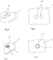
- FIGS. 1 to 5 A first embodiment will be described.
- a luminaire comprises a carrier 2, which is formed from sheet metal, preferably from a bottom portion of a lamp housing, and a printed circuit board 4, which is arranged thereon.
- the printed circuit board 4 has a plurality of LEDs 6, which are arranged along a row in the embodiment shown.
- first sheet metal sections 10 are punched out of the carrier by means of a punching / bending process and bent out in the direction of the contact surface on which the circuit board 4 is to be placed on the carrier.
- FIGS. 4 and 5 show the sheet metal sections 10 in the form of two sheet metal tongues, which are punched out of the carrier 2 approximately along each of a semicircle and are bent out along each of a straight edge of the plane of the carrier 2.
- the printed circuit board 4 is placed on the carrier 2, so that the sheet metal sections 10 extend through an opening 12 in the circuit board 4. Subsequently, the sheet metal sections 10 are bent to the outside, so that they surround the edge of the opening 12 on the side facing away from the carrier of the circuit board 4. As a result, a positive fastening of the printed circuit board 4 is formed on the carrier 2. Since the sheet metal portion 10 includes two opposing tongues, the printed circuit board 4 can not move in any direction parallel to the surface of the carrier 2. Theoretically, the circuit board 4 could still rotate around the sheet metal sections of the attachment. However, this is precluded by the fact that either further of the previously described fasteners are provided on the carrier, or that the printed circuit board 4 rests on at least one edge on the carrier 2, so that a rotation is prevented.
- the sheet metal portion 10 comprises no single tongues but a continuous cylindrical portion which is pushed out of the material of the carrier 2 in the direction of the contact surface on which the printed circuit board 4 is applied.
- the circuit board 4 has the same opening 12 as explained in the previously described embodiment. With this opening 12, the circuit board 4 is inserted over the cylindrical portion 10 'of the carrier. Subsequently, the cylindrical portion 10 'on the side facing away from the carrier 2 of the circuit board 4 is umbörtelt. For example, with a ball whose diameter is slightly larger than the diameter of the cylindrical portion 10 ', the edge of the cylindrical portion 10' are uniformly turned over to the outside by pressing the ball.
- FIGS. 8 to 10 A further alternative embodiment of the luminaire is described, the same reference numerals as previously used being used for corresponding features.
- the printed circuit boards are elongated with e.g. a row or a double row of LEDs 6.
- the openings 12 are provided in the form of cutouts at the edge. In each of these cutouts, a sheet metal section 10, which is bent out of the lying below the circuit board 4 plate carrier 2.
- the printed circuit boards 4 are held only at the longitudinal edges, wherein the cutout 12 is slightly longer than the sheet metal section 10, so that the circuit boards 4 can expand independently of the underlying support 2 with thermal heating. This has an advantage especially when using very long printed circuit boards in linear luminaires. A long continuous circuit board 4 is cheaper to manufacture.
- the openings 12 in the form of cutouts at the longitudinal edges have the advantage that the circuit board itself is not interrupted, so that no structural or color differences are to be perceived on the light exit side.
- an additional lighting component in the form of a lens cover 14 is arranged on the printed circuit board 4 directly above the LEDs 6.
- the lens cover 14 has individual lens elements associated with one or a group of LEDs 6, respectively.
- the lens cover 14 is fastened by means of the same sheet metal sections 10 as the printed circuit board 4.
- the lens cover has feet 16, which are formed in the form of a bend in the direction of the carrier 2.
- the feet 16 engage in each case an opening 12 of the circuit board 4 adjacent to the sheet metal section 10, wherein the sheet metal portion 10 is bent over the foot 16, so that both the lens cover 14 and the circuit board 4 is held by the sheet metal portion 10 on the support 2.
- At least one further positioning foot 18 can be provided on the lens cover 14 or any other additional lighting component, which also engages in an opening 12 of the printed circuit board.
- the positioning foot is not secured with a sheet metal portion 10 of the carrier, but is only with the circuit board 4 in connection.
- the positioning foot 18 can fit precisely into the printed circuit board in order to position the lens cover or another additional lighting component 14 with respect to the LEDs 6.
- the lens cover 14 can move along with the printed circuit board 14 during thermal expansion, so that the alignment of the lenses with respect to the LEDs is maintained even with a different thermal expansion relative to the carrier 2.
- some of the sheet metal sections 10 can engage in openings 12 of the printed circuit board 4 without attacking the additional lighting component 14.
- a positioning foot 18 may engage a side cutout of the circuit board to position a light cover, while on the opposite side a shorter sheet section 10 engages a cutout 12 of the circuit board to hold the circuit board.
- FIG. 10 illustrated embodiment, different circuit boards 4, each with the same lighting components, as previously described, are connected.
- two different circuit boards 4 are shown, with a narrower version only one single row of LEDs 6, while the wider version has a double row of LEDs 6.
- the carrier 2 and the lens cover 14 can remain the same, so that a system of different lights can be formed from partially identical components.
- FIG. 10 is understood that only one of the two printed circuit boards 4 shown one above the other is used in the lamp.
- the different widths of printed circuit boards 4 can interact with the same sheet metal portion 10 of the support 2, the cutouts 12 are configured T-shaped in the wider circuit board 4 to engage deeper in the circuit board 4, compared to the simple cutouts 12 in the narrower Printed circuit board 4.
- a terminal 20 is provided on the circuit board 4, which engages in an opening 22 of the carrier in order to be contacted by the opposite side can.
- the opening 22 does not have a sheet portion protruding from the opening 22 toward the circuit board. The opening 22 is completely punched out.
- more than two tongues may be provided as sheet metal sections. There may be three or more tongues along a circumference of the circumference, each bent outwardly around the circuit board. The tongues can each engage individually through an opening of the circuit board or more than two tongues reach through an opening.
- the opening in the circuit board may, but need not, be circular.
Landscapes
- Engineering & Computer Science (AREA)
- General Engineering & Computer Science (AREA)
- Fastening Of Light Sources Or Lamp Holders (AREA)
- Non-Portable Lighting Devices Or Systems Thereof (AREA)
- Arrangement Of Elements, Cooling, Sealing, Or The Like Of Lighting Devices (AREA)
Claims (14)
- Luminaire avec un circuit imprimé (4) et un boîtier, qui comprend au moins un support (2) en tôle, qui sert de surface d'appui pour le circuit imprimé (4), qui supporte une ou plusieurs LED (6),
le circuit imprimé (4) comprenant au moins une ouverture (12) à travers laquelle s'étend une portion de tôle (10 ; 10'), reliée d'une seule pièce avec le support (2), qui est pliée, sur le côté du circuit imprimé (4) opposé à la surface d'appui, au-dessus d'un bord de l'ouverture (12), caractérisé en ce que, sur le côté du circuit imprimé (4) opposé au support (2), est disposé un composant de luminaire supplémentaire (14) qui est maintenu avec le circuit imprimé (4) au moyen de la portion de tôle (10). - Luminaire selon la revendication 1, la portion de tôle (10) comprenant au moins une languette en tôle.
- Luminaire selon l'une des revendications précédentes, l'ouverture (12) étant réalisée sous la forme d'un trou dans le circuit imprimé (4) ou sous la forme d'un évidement sur le bord du circuit imprimé (4).
- Luminaire selon l'une des revendications précédentes, la portion de tôle (10 ; 10') comprenant plusieurs parties continues ou discontinues qui entourent des portions de bords opposées de l'ouverture.
- Luminaire selon la revendication 4, les plusieurs parties étant constituées de plusieurs languettes en tôle opposées.
- Luminaire selon la revendication 4, les parties étant constituées d'une zone cylindrique continue qui s'étend le long du bord de l'ouverture (12) à travers celle-ci et qui est sertie sur le côté du circuit imprimé (4) opposé à la surface d'appui.
- Luminaire selon l'une des revendications précédentes, le circuit imprimé (4) s'appuyant sur toute sa surface contre le support (2) avec ou sans une couche intermédiaire.
- Luminaire selon la revendication 7, une couche d'isolation étant disposée entre le circuit imprimé (4) et la surface d'appui.
- Luminaire selon l'une des revendications précédentes, le support (2) faisant partie d'un boîtier de luminaire constitué de tôle.
- Luminaire selon l'une des revendications précédentes, la tôle du support (2) présentant une épaisseur de matériau de 0,4 mm à 2 mm, de préférence de 0,5 mm à 1 mm.
- Luminaire selon l'une des revendications précédentes, le circuit imprimé (4) étant fixé sur le support (2) sans autres dispositifs de fixation qu'une ou plusieurs portions de tôle (10 ; 10') constituées de la tôle du support.
- Luminaire selon l'une des revendications précédentes, le composant de luminaire supplémentaire (14) s'emboîtant avec un ou plusieurs pieds (16) dans au moins une des ouvertures (12) du circuit imprimé (4).
- Luminaire selon l'une des revendications précédentes, le composant de luminaire supplémentaire (14) étant un support de lentilles qui comprend plusieurs lentilles correspondant chacune à au moins une LED.
- Luminaire selon l'une des revendications précédentes, le circuit imprimé (4) étant maintenu uniquement au niveau de bords longitudinaux de façon à permettre une dilatation longitudinale du circuit imprimé (4) par rapport au support (2).
Applications Claiming Priority (1)
| Application Number | Priority Date | Filing Date | Title |
|---|---|---|---|
| DE102016109371.8A DE102016109371A1 (de) | 2016-05-20 | 2016-05-20 | Leuchte mit LED-Leiterplatte auf Blechträger |
Publications (2)
| Publication Number | Publication Date |
|---|---|
| EP3246623A1 EP3246623A1 (fr) | 2017-11-22 |
| EP3246623B1 true EP3246623B1 (fr) | 2018-12-19 |
Family
ID=58738957
Family Applications (1)
| Application Number | Title | Priority Date | Filing Date |
|---|---|---|---|
| EP17171954.5A Active EP3246623B1 (fr) | 2016-05-20 | 2017-05-19 | Éclairage comprenant une carte de circuit imprimé del sur un support de tôle |
Country Status (2)
| Country | Link |
|---|---|
| EP (1) | EP3246623B1 (fr) |
| DE (1) | DE102016109371A1 (fr) |
Families Citing this family (1)
| Publication number | Priority date | Publication date | Assignee | Title |
|---|---|---|---|---|
| EP3805637A1 (fr) * | 2019-10-07 | 2021-04-14 | Lumileds Holding B.V. | Dispositif électronique et procédé de fabrication d'un dispositif électronique |
Family Cites Families (10)
| Publication number | Priority date | Publication date | Assignee | Title |
|---|---|---|---|---|
| US2321755A (en) * | 1939-08-05 | 1943-06-15 | Detroit Harvester Co | Device for connecting sheet metal panels |
| JPH09267140A (ja) * | 1996-04-01 | 1997-10-14 | Nissan Motor Co Ltd | 板材の締結方法およびその締結方法に用いるポンチ |
| JP2000349348A (ja) * | 1999-03-31 | 2000-12-15 | Toyoda Gosei Co Ltd | 短波長ledランプユニット |
| CN201083924Y (zh) * | 2007-06-22 | 2008-07-09 | 群康科技(深圳)有限公司 | 背光模组和液晶显示装置 |
| KR100939382B1 (ko) * | 2009-06-24 | 2010-01-29 | (주)엘포인트 | 엘이디 모듈 기판과 섀시의 결합장치 및 이를 이용한 백라이트 |
| DE102010062331B4 (de) * | 2010-12-02 | 2012-07-05 | Osram Ag | Herstellungsverfahren für eine LED-Lampe und eine entsprechende LED-Lampe |
| TW201331503A (zh) * | 2012-01-20 | 2013-08-01 | Taiwan Fu Hsing Ind Co Ltd | 燈具結構及其固定座 |
| DE102013214620A1 (de) * | 2013-07-26 | 2015-01-29 | Itz Innovations- Und Technologiezentrum Gmbh | Niederhalter |
| DE202014100952U1 (de) * | 2014-03-03 | 2015-06-09 | Zumtobel Lighting Gmbh | Leuchte mit Leuchtmitteln für direkte und indirekte Lichtabgabe |
| DE202015104043U1 (de) * | 2014-12-08 | 2016-03-09 | Tridonic Gmbh & Co Kg | Befestigungsbrücke zur Befestigung von LED-Modulen an Befestigungsschienen |
-
2016
- 2016-05-20 DE DE102016109371.8A patent/DE102016109371A1/de not_active Ceased
-
2017
- 2017-05-19 EP EP17171954.5A patent/EP3246623B1/fr active Active
Non-Patent Citations (1)
| Title |
|---|
| None * |
Also Published As
| Publication number | Publication date |
|---|---|
| EP3246623A1 (fr) | 2017-11-22 |
| DE102016109371A1 (de) | 2017-11-23 |
Similar Documents
| Publication | Publication Date | Title |
|---|---|---|
| EP2827053B1 (fr) | Dispositif d'éclairage | |
| EP2521876B1 (fr) | Dispositif d'éclairage à del et procédé de production d'un dispositif d'éclairage à del | |
| EP2534416B1 (fr) | Élément de fixation, module d'éclairage et dispositif d'éclairage | |
| DE102010052020B4 (de) | Beleuchtungs- und/oder Anzeigenvorrichtung | |
| EP2766657B1 (fr) | Module led pourvu d'un corps de refroidissement | |
| WO2012037588A1 (fr) | Dispositif de fixation et de mise en contact d'un moyen d'éclairage et/ou d'un module d'éclairage, et luminaire | |
| AT12910U1 (de) | Vorrichtung zum befestigen und kontaktieren eines leuchtmittels und/oder eines leuchtmoduls, sowie leuchte | |
| WO2012032191A1 (fr) | Dispositif d'éclairage à del | |
| DE202015106042U1 (de) | Leiterplatte | |
| EP2642613B1 (fr) | Système de montage de lampes | |
| EP3246623B1 (fr) | Éclairage comprenant une carte de circuit imprimé del sur un support de tôle | |
| DE212019000465U1 (de) | LED-Röhrenlampe | |
| EP2711750B1 (fr) | Lampe à DEL dotée d'une plaque de guide d'ondes optiques | |
| EP2702322B1 (fr) | Appareil de commande de lampe à fixation sans outil | |
| AT518330B1 (de) | Leuchte | |
| AT15286U1 (de) | Längliche LED-Leuchte | |
| DE202016101380U1 (de) | Montageelement aus LED, LED-Anschlusselement und Anschlusskontakt sowie Anschlusselemente zur Herstellung einer solchen Montageeinheit | |
| EP2789906B1 (fr) | Dispositif d'éclairage | |
| EP3446031B1 (fr) | Appareil d'éclairage d'armoire de distribution pourvu d'une platine à source lumineuse réglable | |
| EP2143989A1 (fr) | Unité d'éclairage, module DEL et procédé | |
| DE10234459B4 (de) | Verbindungselement zum Befestigen eines optischen Leuchtenbauteils an einer Leuchte und Leuchte | |
| DE202016101385U1 (de) | Montageelement aus LED, LED-Anschlusselement und Anschlussleiter sowie Anschlusselemente zur Herstellung einer solchen Montageeinheit | |
| EP3001856A1 (fr) | Dispositif d'éclairage | |
| EP3339724B1 (fr) | Éclairage à rail de support et élément de fixation pour une platine | |
| DE102009007612A1 (de) | Vorrichtung zur Wärmeabfuhr und Verfahren zu ihrer Herstellung |
Legal Events
| Date | Code | Title | Description |
|---|---|---|---|
| PUAI | Public reference made under article 153(3) epc to a published international application that has entered the european phase |
Free format text: ORIGINAL CODE: 0009012 |
|
| STAA | Information on the status of an ep patent application or granted ep patent |
Free format text: STATUS: THE APPLICATION HAS BEEN PUBLISHED |
|
| AK | Designated contracting states |
Kind code of ref document: A1 Designated state(s): AL AT BE BG CH CY CZ DE DK EE ES FI FR GB GR HR HU IE IS IT LI LT LU LV MC MK MT NL NO PL PT RO RS SE SI SK SM TR |
|
| AX | Request for extension of the european patent |
Extension state: BA ME |
|
| STAA | Information on the status of an ep patent application or granted ep patent |
Free format text: STATUS: REQUEST FOR EXAMINATION WAS MADE |
|
| 17P | Request for examination filed |
Effective date: 20180518 |
|
| RBV | Designated contracting states (corrected) |
Designated state(s): AL AT BE BG CH CY CZ DE DK EE ES FI FR GB GR HR HU IE IS IT LI LT LU LV MC MK MT NL NO PL PT RO RS SE SI SK SM TR |
|
| GRAP | Despatch of communication of intention to grant a patent |
Free format text: ORIGINAL CODE: EPIDOSNIGR1 |
|
| STAA | Information on the status of an ep patent application or granted ep patent |
Free format text: STATUS: GRANT OF PATENT IS INTENDED |
|
| RIC1 | Information provided on ipc code assigned before grant |
Ipc: F21V 19/00 20060101AFI20180619BHEP Ipc: F16B 17/00 20060101ALI20180619BHEP Ipc: F21V 5/00 20150101ALI20180619BHEP Ipc: F16B 5/04 20060101ALI20180619BHEP Ipc: F21S 4/28 20160101ALI20180619BHEP Ipc: F21Y 103/10 20160101ALN20180619BHEP Ipc: F21Y 115/10 20160101ALN20180619BHEP |
|
| INTG | Intention to grant announced |
Effective date: 20180704 |
|
| GRAS | Grant fee paid |
Free format text: ORIGINAL CODE: EPIDOSNIGR3 |
|
| GRAA | (expected) grant |
Free format text: ORIGINAL CODE: 0009210 |
|
| STAA | Information on the status of an ep patent application or granted ep patent |
Free format text: STATUS: THE PATENT HAS BEEN GRANTED |
|
| AK | Designated contracting states |
Kind code of ref document: B1 Designated state(s): AL AT BE BG CH CY CZ DE DK EE ES FI FR GB GR HR HU IE IS IT LI LT LU LV MC MK MT NL NO PL PT RO RS SE SI SK SM TR |
|
| REG | Reference to a national code |
Ref country code: GB Ref legal event code: FG4D Free format text: NOT ENGLISH |
|
| REG | Reference to a national code |
Ref country code: CH Ref legal event code: EP |
|
| REG | Reference to a national code |
Ref country code: IE Ref legal event code: FG4D Free format text: LANGUAGE OF EP DOCUMENT: GERMAN |
|
| REG | Reference to a national code |
Ref country code: DE Ref legal event code: R096 Ref document number: 502017000528 Country of ref document: DE |
|
| REG | Reference to a national code |
Ref country code: AT Ref legal event code: REF Ref document number: 1079135 Country of ref document: AT Kind code of ref document: T Effective date: 20190115 |
|
| REG | Reference to a national code |
Ref country code: NL Ref legal event code: MP Effective date: 20181219 |
|
| PG25 | Lapsed in a contracting state [announced via postgrant information from national office to epo] |
Ref country code: NO Free format text: LAPSE BECAUSE OF FAILURE TO SUBMIT A TRANSLATION OF THE DESCRIPTION OR TO PAY THE FEE WITHIN THE PRESCRIBED TIME-LIMIT Effective date: 20190319 Ref country code: FI Free format text: LAPSE BECAUSE OF FAILURE TO SUBMIT A TRANSLATION OF THE DESCRIPTION OR TO PAY THE FEE WITHIN THE PRESCRIBED TIME-LIMIT Effective date: 20181219 Ref country code: BG Free format text: LAPSE BECAUSE OF FAILURE TO SUBMIT A TRANSLATION OF THE DESCRIPTION OR TO PAY THE FEE WITHIN THE PRESCRIBED TIME-LIMIT Effective date: 20190319 Ref country code: LT Free format text: LAPSE BECAUSE OF FAILURE TO SUBMIT A TRANSLATION OF THE DESCRIPTION OR TO PAY THE FEE WITHIN THE PRESCRIBED TIME-LIMIT Effective date: 20181219 Ref country code: HR Free format text: LAPSE BECAUSE OF FAILURE TO SUBMIT A TRANSLATION OF THE DESCRIPTION OR TO PAY THE FEE WITHIN THE PRESCRIBED TIME-LIMIT Effective date: 20181219 Ref country code: LV Free format text: LAPSE BECAUSE OF FAILURE TO SUBMIT A TRANSLATION OF THE DESCRIPTION OR TO PAY THE FEE WITHIN THE PRESCRIBED TIME-LIMIT Effective date: 20181219 |
|
| REG | Reference to a national code |
Ref country code: LT Ref legal event code: MG4D |
|
| PG25 | Lapsed in a contracting state [announced via postgrant information from national office to epo] |
Ref country code: RS Free format text: LAPSE BECAUSE OF FAILURE TO SUBMIT A TRANSLATION OF THE DESCRIPTION OR TO PAY THE FEE WITHIN THE PRESCRIBED TIME-LIMIT Effective date: 20181219 Ref country code: SE Free format text: LAPSE BECAUSE OF FAILURE TO SUBMIT A TRANSLATION OF THE DESCRIPTION OR TO PAY THE FEE WITHIN THE PRESCRIBED TIME-LIMIT Effective date: 20181219 Ref country code: AL Free format text: LAPSE BECAUSE OF FAILURE TO SUBMIT A TRANSLATION OF THE DESCRIPTION OR TO PAY THE FEE WITHIN THE PRESCRIBED TIME-LIMIT Effective date: 20181219 Ref country code: GR Free format text: LAPSE BECAUSE OF FAILURE TO SUBMIT A TRANSLATION OF THE DESCRIPTION OR TO PAY THE FEE WITHIN THE PRESCRIBED TIME-LIMIT Effective date: 20190320 |
|
| PG25 | Lapsed in a contracting state [announced via postgrant information from national office to epo] |
Ref country code: NL Free format text: LAPSE BECAUSE OF FAILURE TO SUBMIT A TRANSLATION OF THE DESCRIPTION OR TO PAY THE FEE WITHIN THE PRESCRIBED TIME-LIMIT Effective date: 20181219 |
|
| PG25 | Lapsed in a contracting state [announced via postgrant information from national office to epo] |
Ref country code: ES Free format text: LAPSE BECAUSE OF FAILURE TO SUBMIT A TRANSLATION OF THE DESCRIPTION OR TO PAY THE FEE WITHIN THE PRESCRIBED TIME-LIMIT Effective date: 20181219 Ref country code: PL Free format text: LAPSE BECAUSE OF FAILURE TO SUBMIT A TRANSLATION OF THE DESCRIPTION OR TO PAY THE FEE WITHIN THE PRESCRIBED TIME-LIMIT Effective date: 20181219 Ref country code: IT Free format text: LAPSE BECAUSE OF FAILURE TO SUBMIT A TRANSLATION OF THE DESCRIPTION OR TO PAY THE FEE WITHIN THE PRESCRIBED TIME-LIMIT Effective date: 20181219 Ref country code: PT Free format text: LAPSE BECAUSE OF FAILURE TO SUBMIT A TRANSLATION OF THE DESCRIPTION OR TO PAY THE FEE WITHIN THE PRESCRIBED TIME-LIMIT Effective date: 20190419 Ref country code: CZ Free format text: LAPSE BECAUSE OF FAILURE TO SUBMIT A TRANSLATION OF THE DESCRIPTION OR TO PAY THE FEE WITHIN THE PRESCRIBED TIME-LIMIT Effective date: 20181219 |
|
| PG25 | Lapsed in a contracting state [announced via postgrant information from national office to epo] |
Ref country code: RO Free format text: LAPSE BECAUSE OF FAILURE TO SUBMIT A TRANSLATION OF THE DESCRIPTION OR TO PAY THE FEE WITHIN THE PRESCRIBED TIME-LIMIT Effective date: 20181219 Ref country code: EE Free format text: LAPSE BECAUSE OF FAILURE TO SUBMIT A TRANSLATION OF THE DESCRIPTION OR TO PAY THE FEE WITHIN THE PRESCRIBED TIME-LIMIT Effective date: 20181219 Ref country code: SM Free format text: LAPSE BECAUSE OF FAILURE TO SUBMIT A TRANSLATION OF THE DESCRIPTION OR TO PAY THE FEE WITHIN THE PRESCRIBED TIME-LIMIT Effective date: 20181219 Ref country code: IS Free format text: LAPSE BECAUSE OF FAILURE TO SUBMIT A TRANSLATION OF THE DESCRIPTION OR TO PAY THE FEE WITHIN THE PRESCRIBED TIME-LIMIT Effective date: 20190419 Ref country code: SK Free format text: LAPSE BECAUSE OF FAILURE TO SUBMIT A TRANSLATION OF THE DESCRIPTION OR TO PAY THE FEE WITHIN THE PRESCRIBED TIME-LIMIT Effective date: 20181219 |
|
| REG | Reference to a national code |
Ref country code: DE Ref legal event code: R097 Ref document number: 502017000528 Country of ref document: DE |
|
| PLBE | No opposition filed within time limit |
Free format text: ORIGINAL CODE: 0009261 |
|
| STAA | Information on the status of an ep patent application or granted ep patent |
Free format text: STATUS: NO OPPOSITION FILED WITHIN TIME LIMIT |
|
| PG25 | Lapsed in a contracting state [announced via postgrant information from national office to epo] |
Ref country code: DK Free format text: LAPSE BECAUSE OF FAILURE TO SUBMIT A TRANSLATION OF THE DESCRIPTION OR TO PAY THE FEE WITHIN THE PRESCRIBED TIME-LIMIT Effective date: 20181219 |
|
| 26N | No opposition filed |
Effective date: 20190920 |
|
| PG25 | Lapsed in a contracting state [announced via postgrant information from national office to epo] |
Ref country code: MC Free format text: LAPSE BECAUSE OF FAILURE TO SUBMIT A TRANSLATION OF THE DESCRIPTION OR TO PAY THE FEE WITHIN THE PRESCRIBED TIME-LIMIT Effective date: 20181219 |
|
| REG | Reference to a national code |
Ref country code: BE Ref legal event code: MM Effective date: 20190531 |
|
| PG25 | Lapsed in a contracting state [announced via postgrant information from national office to epo] |
Ref country code: SI Free format text: LAPSE BECAUSE OF FAILURE TO SUBMIT A TRANSLATION OF THE DESCRIPTION OR TO PAY THE FEE WITHIN THE PRESCRIBED TIME-LIMIT Effective date: 20181219 Ref country code: LU Free format text: LAPSE BECAUSE OF NON-PAYMENT OF DUE FEES Effective date: 20190519 |
|
| REG | Reference to a national code |
Ref country code: DE Ref legal event code: R082 Ref document number: 502017000528 Country of ref document: DE Representative=s name: BOEHMERT & BOEHMERT ANWALTSPARTNERSCHAFT MBB -, DE Ref country code: DE Ref legal event code: R081 Ref document number: 502017000528 Country of ref document: DE Owner name: SITECO GMBH, DE Free format text: FORMER OWNER: SITECO BELEUCHTUNGSTECHNIK GMBH, 83301 TRAUNREUT, DE |
|
| PG25 | Lapsed in a contracting state [announced via postgrant information from national office to epo] |
Ref country code: TR Free format text: LAPSE BECAUSE OF FAILURE TO SUBMIT A TRANSLATION OF THE DESCRIPTION OR TO PAY THE FEE WITHIN THE PRESCRIBED TIME-LIMIT Effective date: 20181219 |
|
| PG25 | Lapsed in a contracting state [announced via postgrant information from national office to epo] |
Ref country code: IE Free format text: LAPSE BECAUSE OF NON-PAYMENT OF DUE FEES Effective date: 20190519 |
|
| PG25 | Lapsed in a contracting state [announced via postgrant information from national office to epo] |
Ref country code: BE Free format text: LAPSE BECAUSE OF NON-PAYMENT OF DUE FEES Effective date: 20190531 |
|
| REG | Reference to a national code |
Ref country code: AT Ref legal event code: PC Ref document number: 1079135 Country of ref document: AT Kind code of ref document: T Owner name: SITECO GMBH, DE Effective date: 20201028 |
|
| PG25 | Lapsed in a contracting state [announced via postgrant information from national office to epo] |
Ref country code: LI Free format text: LAPSE BECAUSE OF NON-PAYMENT OF DUE FEES Effective date: 20200531 Ref country code: CH Free format text: LAPSE BECAUSE OF NON-PAYMENT OF DUE FEES Effective date: 20200531 |
|
| PG25 | Lapsed in a contracting state [announced via postgrant information from national office to epo] |
Ref country code: CY Free format text: LAPSE BECAUSE OF FAILURE TO SUBMIT A TRANSLATION OF THE DESCRIPTION OR TO PAY THE FEE WITHIN THE PRESCRIBED TIME-LIMIT Effective date: 20181219 |
|
| PG25 | Lapsed in a contracting state [announced via postgrant information from national office to epo] |
Ref country code: MT Free format text: LAPSE BECAUSE OF FAILURE TO SUBMIT A TRANSLATION OF THE DESCRIPTION OR TO PAY THE FEE WITHIN THE PRESCRIBED TIME-LIMIT Effective date: 20181219 Ref country code: HU Free format text: LAPSE BECAUSE OF FAILURE TO SUBMIT A TRANSLATION OF THE DESCRIPTION OR TO PAY THE FEE WITHIN THE PRESCRIBED TIME-LIMIT; INVALID AB INITIO Effective date: 20170519 |
|
| GBPC | Gb: european patent ceased through non-payment of renewal fee |
Effective date: 20210519 |
|
| PG25 | Lapsed in a contracting state [announced via postgrant information from national office to epo] |
Ref country code: GB Free format text: LAPSE BECAUSE OF NON-PAYMENT OF DUE FEES Effective date: 20210519 |
|
| PG25 | Lapsed in a contracting state [announced via postgrant information from national office to epo] |
Ref country code: MK Free format text: LAPSE BECAUSE OF FAILURE TO SUBMIT A TRANSLATION OF THE DESCRIPTION OR TO PAY THE FEE WITHIN THE PRESCRIBED TIME-LIMIT Effective date: 20181219 |
|
| PGFP | Annual fee paid to national office [announced via postgrant information from national office to epo] |
Ref country code: DE Payment date: 20240517 Year of fee payment: 8 |
|
| PGFP | Annual fee paid to national office [announced via postgrant information from national office to epo] |
Ref country code: AT Payment date: 20240517 Year of fee payment: 8 |
|
| PGFP | Annual fee paid to national office [announced via postgrant information from national office to epo] |
Ref country code: FR Payment date: 20240523 Year of fee payment: 8 |