EP3540742A2 - Verfahren und vorrichtung zur entriegelung von steuerstangenantriebswellen in druckwasserreaktoren - Google Patents
Verfahren und vorrichtung zur entriegelung von steuerstangenantriebswellen in druckwasserreaktoren Download PDFInfo
- Publication number
- EP3540742A2 EP3540742A2 EP19162974.0A EP19162974A EP3540742A2 EP 3540742 A2 EP3540742 A2 EP 3540742A2 EP 19162974 A EP19162974 A EP 19162974A EP 3540742 A2 EP3540742 A2 EP 3540742A2
- Authority
- EP
- European Patent Office
- Prior art keywords
- latch
- section
- assembly
- control rod
- unlatching
- Prior art date
- Legal status (The legal status is an assumption and is not a legal conclusion. Google has not performed a legal analysis and makes no representation as to the accuracy of the status listed.)
- Granted
Links
Images




Classifications
-
- G—PHYSICS
- G21—NUCLEAR PHYSICS; NUCLEAR ENGINEERING
- G21C—NUCLEAR REACTORS
- G21C19/00—Arrangements for treating, for handling, or for facilitating the handling of, fuel or other materials which are used within the reactor, e.g. within its pressure vessel
- G21C19/02—Details of handling arrangements
- G21C19/10—Lifting devices or pulling devices adapted for co-operation with fuel elements or with control elements
- G21C19/105—Lifting devices or pulling devices adapted for co-operation with fuel elements or with control elements with grasping or spreading coupling elements
-
- G—PHYSICS
- G21—NUCLEAR PHYSICS; NUCLEAR ENGINEERING
- G21C—NUCLEAR REACTORS
- G21C19/00—Arrangements for treating, for handling, or for facilitating the handling of, fuel or other materials which are used within the reactor, e.g. within its pressure vessel
- G21C19/02—Details of handling arrangements
- G21C19/10—Lifting devices or pulling devices adapted for co-operation with fuel elements or with control elements
- G21C19/115—Lifting devices or pulling devices adapted for co-operation with fuel elements or with control elements with latching devices and ball couplings
-
- G—PHYSICS
- G21—NUCLEAR PHYSICS; NUCLEAR ENGINEERING
- G21C—NUCLEAR REACTORS
- G21C19/00—Arrangements for treating, for handling, or for facilitating the handling of, fuel or other materials which are used within the reactor, e.g. within its pressure vessel
- G21C19/02—Details of handling arrangements
- G21C19/10—Lifting devices or pulling devices adapted for co-operation with fuel elements or with control elements
- G21C19/11—Lifting devices or pulling devices adapted for co-operation with fuel elements or with control elements with revolving coupling elements, e.g. socket coupling
-
- G—PHYSICS
- G21—NUCLEAR PHYSICS; NUCLEAR ENGINEERING
- G21C—NUCLEAR REACTORS
- G21C7/00—Control of nuclear reaction
- G21C7/06—Control of nuclear reaction by application of neutron-absorbing material, i.e. material with absorption cross-section very much in excess of reflection cross-section
- G21C7/08—Control of nuclear reaction by application of neutron-absorbing material, i.e. material with absorption cross-section very much in excess of reflection cross-section by displacement of solid control elements, e.g. control rods
- G21C7/10—Construction of control elements
- G21C7/117—Clusters of control rods; Spider construction
-
- Y—GENERAL TAGGING OF NEW TECHNOLOGICAL DEVELOPMENTS; GENERAL TAGGING OF CROSS-SECTIONAL TECHNOLOGIES SPANNING OVER SEVERAL SECTIONS OF THE IPC; TECHNICAL SUBJECTS COVERED BY FORMER USPC CROSS-REFERENCE ART COLLECTIONS [XRACs] AND DIGESTS
- Y02—TECHNOLOGIES OR APPLICATIONS FOR MITIGATION OR ADAPTATION AGAINST CLIMATE CHANGE
- Y02E—REDUCTION OF GREENHOUSE GAS [GHG] EMISSIONS, RELATED TO ENERGY GENERATION, TRANSMISSION OR DISTRIBUTION
- Y02E30/00—Energy generation of nuclear origin
- Y02E30/30—Nuclear fission reactors
Definitions
- the present disclosure relates generally to control rod drive shafts (CRDSs) in nuclear reactors and more specifically to a method and device for unlatching CRDSs in pressurized water reactors (PWRs).
- CRDSs control rod drive shafts
- PWRs pressurized water reactors
- Controls rods are used in nuclear reactors to control the rate of fission.
- the control rods typically are arranged in control rod clusters assemblies.
- Each control rod cluster assembly can include a spider with the control rods vertically extending downwardly from the spider.
- the control rod cluster assembly can be lowered via the spider into guide thimbles of the fuel assembly of a PWR to regulate the reactivity of the nuclear reactor core.
- a lower end of a CRDS is connected to the spider and an upper end of the CRDS is connected to a control rod drive mechanism fixed to a closure head of the pressure vessel.
- Existing tools require access to nitrogen/air which contributes to additional setup time and additional consumables, and require two personnel for operation.
- the existing tool has a tendency for flooded air cylinders which requires replacement during tool refurbishment and requires sites to keep continuous air/nitrogen hooked up to the tool if the site plans to leave the tool hanging on the cavity wall during reactor cavity flood up.
- the tool of the present disclosure is not powered by air cylinder, but is instead mechanically actuated, and may be hung in a flooded reactor cavity without worry of flooding air cylinders, and may be more quickly set up with less space required on the refueling bridge. Hence little to no refurb is required for the tool and no measures need to be put in place as the tool hangs in a flooded cavity.
- Unlatching tool 10 includes, at an upper end 12 thereof, a bail assembly 14 configured for being attached to a refueling bridge hoist. Bail assembly 14 supports a mechanical gripper actuator 16 configured for actuating grippers 30a.
- Upper base section 20 is non-rotatably fixed to bail assembly 14 and includes a guide 22 configured for a guiding latch actuator 24 configured for actuating latches 34 via outer assembly 18. More specifically, an upper end of upper base section 20 is fixed to a base plate 14a of bail assembly 14. An upper end of outer assembly 18 is rotatably received inside of upper base section 20. More specifically, an upper end of upper outer section 18a is rotatably received inside of upper base section 20.
- Unlatching tool 10 also includes an inner support assembly 26, which is a cylindrical mast, formed by a plurality of inner support sections 26a to 26i.
- Inner support assembly 26 is positioned inside of outer assembly 18.
- Inner support assembly 26 is non-rotatably fixed with respect to bail assembly 14.
- outer assembly 18 is rotatable with respect to inner support assembly 26.
- Inner support sections 26a to 26i are non-rotatably fixed to each other and are non-rotatably fixed to bail assembly 14. More specifically, an upper end of upper inner support section 26a is fixed to base plate 14a of bail assembly 14.
- Unlatching tool 10 further includes a movable rod 28.
- Rod 28 movably connects a gripper assembly 30 to the base.
- Rod 28 extends inside of inner support assembly 26.
- Rod 28 is movably fixed to bail assembly 14 by actuator 16. More specifically, rod 28 is axially movably fixed to bail assembly 14 by actuator 16, and is axially movable within inner support assembly 26.
- Movable rod 28 includes a plurality of rod sections 28a to 28e.
- Mechanical actuator 16 is fixed to the base and configured for raising and lowering rod 28 to raise and lower gripper assembly 30.
- a lower end of movable 28 engages gripper assembly 30, which is configured for gripping the button of a CRDS.
- Gripper assembly 30 is positioned inside of inner support section 26f and is actuatable by the axial movement of rod 28.
- Gripper assembly 30 includes a grippers 30a ( Figs. 2a to 2c ) inside of a gripper housing 30b.
- a cylindrical bushing 32 is provided radially between gripper housing 30b and inner support section 26f. More specifically, bushing 32 is provided inside of an inner diameter surface of inner support section 26f and outside of an outer diameter surface of housing 30b.
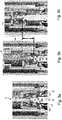
- Figs. 2a to 2c show views of gripper assembly 30 and the lower end of rod 28.
- Fig. 2a shows a perspective view
- Fig. 2b shows a side view
- Fig. 2c shows a radial cross-sectional view along A-A in Fig. 2b .
- the lower end of rod 28 is formed by a lower rod section 28d and a gripper contact section 28e fixed to the lower end of lower rod section 28d.
- Lower rod section 28d includes a threaded shaft 36 including a threaded upper end 36a and a threaded lower end 36b.
- Section 28d further includes a clevis 38 screwed onto threaded upper end 36a and a nut 40 axially aligning clevis 38 on shaft 36.
- Clevis 38 includes two prongs 38a holding a pin 38b, and a cylindrical base 38c having a threaded bore that receives threaded upper end 36a of shaft 36.
- Grippers 30a are rotatably fixed to base section 42a by tangentially fasteners 46 passing through tangentially extending holes 48 formed in base section 42a. Grippers 30a are held on fasteners 46 via bushings 46a. Grippers 30a are rotatable about fasteners 46 within slot 44.
- Grippers 30a are elongated vertically and include an upper surface 31a, a lower surface 31b, an outer surface 31c and an inner surface 31d.
- Outer surface 31c faces away from rod 28 and toward inner support assembly 26 and extends upward from lower surface 31b to upper surface 31a.
- Inner surface 31d faces toward rod 28 and away from inner support assembly 26 and extends upward from lower surface 31b to upper surface 31a.
- Inner surface 31d is provided with three contact sections formed as protrusions - an upper protrusion 33a forming a gripper engagement contact section, an intermediate protrusion 33b forming a gripper release contact section and a lower protrusion 33c forming a gripping section.
- Fig. 2c shows grippers 30a in a non-gripping orientation with gripper contact section 28e contacting intermediate protrusion 33b to hold grippers 30a away from each other 30a. More specifically, a tapered lower surface 37c of gripper contact section 28e contacts a tapered upper surface 49 of protrusion 33b to hold grippers 30a away from each other 30a.
- grippers 30a are in the non-gripping orientation shown in Fig. 2c .
- Upper plate 42b is provided with an annular groove in the lower surface thereof receiving a bushing 50 arranged on shaft 36.
- a spring 52 surrounds a portion of an outer circumferential surface of shaft 36 and axially abuts an upper surface of upper plate 42b.
- Figs. 3a to 3c show radial cross-sectional views illustrating the operation of gripper assembly 30.
- Fig. 3a shows rod 28 moved upward in comparison with the orientation shown in Fig. 2c .
- Rod 28 is moved upward by actuator 16.
- actuator 16 is a screw jack that engages threads of upper rod section 28a of rod 28 to move rod 28 axially upward and downward.
- actuator 16 is mechanically operated to axially move the upper rod section 28a without rotating upper rod section 28a; however, in other embodiments, other kinematics of the actuator 16 combined with upper rod section 28a can generate the motion to raise and lower gripper assembly 30.
- Actuator 16 is mounted on top of base plate 14a of bail assembly 14.
- a cover 55 may be provided over actuator 16 and the upper end of upper rod section 28a.
- Cover 55 includes a lower section 55a surrounding actuator 16 and an upper section 55b on top of lower section 55a surrounding the upper end of upper rod section 55b.
- Upper section 55b includes a slot 55c formed therein allowing an operator to view of a height of the upper end of upper rod section 55b, and upper section 55b may be provided with a numeral scale, such as that on a ruler, to indicate the value of the height based on a position of the top edge of upper rod section 55b.
- CRDS 56 includes an axially movable section 56a, which forms the button, and a stationary section 56b. In order to release CRDS from the attached control rod assembly, movable section 56a is moved upward while stationary section 56b remains in place.
- a lower end of a head 54 of button is defined by an annular groove 58 formed in movable section 56a.
- a c-ring 59 is provided radially between an upper end of stationary section 56b and an outer circumferential surface of movable section 56a.
- Unlatching tool 10 is placed onto CRDS 56 such that the lower end of gripper assembly 30, in particular cylindrical section 42e of lower section 42c, rests on stationary section 56b in an annular space formed between the upper end of stationary section 56b and the outer circumferential surface of movable section 56a.
- Knife edge 42f is configured to contact and open c-ring 59 to allow gripper assembly 30 to bottom out on CRDS 56.
- Fig. 3b shows rod 28 being moved further upward in comparison with the orientation shown in Fig. 3a .
- the moving of rod 28 upward via actuator 16 causes an upper tapered surface 37a of gripper contact section 28e to contact a lower tapered surface 35 of upper protrusion 33a of each gripper 30a.
- This contact causes grippers 33a to rotate about the respective gripper axis GA defined by a center of the respective fastener 46 so upper ends 33d of grippers 30a move radially outward and away from each other and lower ends 33e of grippers 30a move radially inward and toward each other.
- the inward radial movement of lower ends 33e of grippers 30a causes a gripping surface 33f of each lower protrusion 33c to contact an outer circumferential surface 59 of movable section 56a at groove 58.
- Fig. 3c shows rod 28 being moved further upward in comparison with the orientation shown in Fig. 3b .
- Grippers 30a are in the same orientation as in Fig. 3b , with gripping surfaces 33f of each lower protrusions 33c contacting the outer surface of movable section 56a of CRDS 56 at groove 58.
- the moving of rod 28 upward via actuator 16 pulls movable section 56a of CRDS 56 upward by a distance Y such that CRDS 56 is released from the corresponding control rod assembly.
- gripper contact section 28e has forced gripper assembly 30 upward by an uppermost surface 37b of gripper contact section 28e contacting the lower surface of upper plate 42b of gripper assembly 30.
- gripper assembly 30 can be used to reconnect CRDS 56 to the corresponding control rod assembly by gripping movable section 56a at groove 58 and moving gripper assembly 30 downward via the axial movement of rod 28 by actuator 16.
- gripper assembly 30 is moved downward into the position shown in Fig. 3b , rod 28 is moved further downward such that the upper surface of the moves out of contact with upper protrusion 33a and the lower surface 37c of gripper contact section 28e contacts the upper surface 49 of protrusion 33b.
- the downward movement of gripper contact section 28e into the upper surface 49 of protrusion 33b forces the lower end 33e of grippers 30a radially outward, causing grippers 30a to release movable section 56a of CRDS 56.
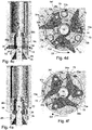
- Fig. 4a shows upper base section 20 fixed to a bottom surface of base plate 14a of bail assembly 14.
- a handle 14b extends upward from base plate 14a and is formed by four post sections that converge above actuator 16 and upper rod section 28a. Handle 14b is used to hang tool 10 from the refueling bridge hoist for operation of actuators 16, 24 operated from the refueling bridge work platform.
- Upper base section 20 extends downward from base section 20 and includes the slot 22 formed therein for the actuation of actuator 24 between a latched orientation and an unlatched orientation, which will be further described with respect to Figs. 4c to 4f .
- actuator 24 For example, if actuator 24 is in the non-actuated position, with spring 64 forcing contact end 24f into enlarged end 22a and thus preventing the circumferential movement actuator 24 and outer section 18, the operator pulls movable portion 24d radially outward to compress spring 64 such that actuator 24 is movable within slot 22 to enlarged end 22b. This actuates actuator 24 and outer assembly 18 from the unlatched orientation to the latched orientation. For example, if actuator 24 is in the non-actuated position, with spring 64 forcing contact end 24f into enlarged end 22b and thus preventing the circumferential movement actuator 24 and outer section 18, the operator pulls movable portion 24d radially outward to compress spring 64 such that actuator 24 is movable within slot 22 to enlarged end 22a. This actuates actuator 24 and outer assembly 18 from the latched orientation to the latched orientation.
- inner support assembly 26 i.e., the upper end of inner support section 26a
- the upper end of inner support assembly 26 is received inside of base section 20 radially inside of outer assembly 19 and is fixed in contact with the lower surface of base plate 14a surrounding a hole 14c formed in base plate 14a.
- Upper rod section 28a of rod 28 is received radially inside of the upper end of inner support assembly 26 and extends upward through base plate 14a via hole 14c.
- Tool 10 is configured such that when inner support section 26g rests on stationary section 56b in such a manner, inner support assembly 26 is axially aligned such that latches 34 are aligned with an annular groove 70 formed in the outer circumferential surface of stationary section 56b, as shown in Fig. 4c . In their unlatched orientation, latches 34 protrude radially outward through windows 72 formed in outer assembly 18 at lower outer section 18c.
- Fig. 5 shows an exploded view of outer section 18c, inner support sections 26g, 26h, 26i and latches 34, and illustrating windows 72
- outer assembly 18 is rotated in rotational direction D1 shown in Fig. 4d .
- This rotation can be accomplished by the operator pulling actuator 24 ( Fig. 4a ) radially outward and moving the actuator 24 in rotation direction D1.
- actuator 24 As actuator 24 is fixed to outer assembly 18, movement of actuator 24 in direction D1 causes outer assembly 18 to also move in direction D1.
- edge 72a of each window 72 contacts a portion 34e of a respective outer surface 34b of the respective latch 34 to force tips 34a of latches 34 radially inward.
- Outer assembly 18 is rotated in direction D1 until an inner circumferential surface 73a of a respective wall section 73 is in contact with the tip 34a of the respective latch 34.
- a contact surface 34c of an inner surface 34d of each 34 latch is forced radially inward into contact with the outer circumferential surface 76 of CRDS 56 at groove 70.
- Inner surface 34d and outer surface 34c merge at tip 34a.
- the contact between contact surface 34c and outer circumferential surface 76 holds tool 10, in particular inner support section 26, axially in place on stationary section 56b of CRDS 56. This latched orientation is shown in Figs. 4e and 4f .
- actuator 24 is held in the latched stop formed by enlarged end 22b of slot 22 (see Fig. 4a ). Accordingly, between the unlatched orientation shown in Figs. 4c and 4d and the latched orientation shown in Figs. 4e and 4f , actuator 24 is rotated in direction D1 from the unlatched stop formed by enlarged end 22a of slot 22 to the latched stop formed by enlarged end 22b of slot 22. Once actuator 24 enters into the latched stop formed by enlarged end 22b of slot 22, the radially inward force applied to movable portion 24d by spring 64 forces end 24f of movable portion 24 into a locked position in enlarged end 22b.
- the invention also relates to the following embodiments.
Landscapes
- Physics & Mathematics (AREA)
- Engineering & Computer Science (AREA)
- Plasma & Fusion (AREA)
- General Engineering & Computer Science (AREA)
- High Energy & Nuclear Physics (AREA)
- Chemical & Material Sciences (AREA)
- Chemical Kinetics & Catalysis (AREA)
- Manipulator (AREA)
- Load-Engaging Elements For Cranes (AREA)
- Monitoring And Testing Of Nuclear Reactors (AREA)
Applications Claiming Priority (1)
| Application Number | Priority Date | Filing Date | Title |
|---|---|---|---|
| US15/923,764 US11289222B2 (en) | 2018-03-16 | 2018-03-16 | Method and device for unlatching control rod drive shafts in pressurized water reactors |
Publications (3)
| Publication Number | Publication Date |
|---|---|
| EP3540742A2 true EP3540742A2 (de) | 2019-09-18 |
| EP3540742A3 EP3540742A3 (de) | 2020-06-03 |
| EP3540742B1 EP3540742B1 (de) | 2022-02-16 |
Family
ID=65817831
Family Applications (1)
| Application Number | Title | Priority Date | Filing Date |
|---|---|---|---|
| EP19162974.0A Active EP3540742B1 (de) | 2018-03-16 | 2019-03-14 | Verfahren und vorrichtung zur entriegelung von steuerstangenantriebswellen in druckwasserreaktoren |
Country Status (2)
| Country | Link |
|---|---|
| US (1) | US11289222B2 (de) |
| EP (1) | EP3540742B1 (de) |
Families Citing this family (3)
| Publication number | Priority date | Publication date | Assignee | Title |
|---|---|---|---|---|
| FR3084509B1 (fr) * | 2018-07-24 | 2021-01-08 | Commissariat Energie Atomique | Dispositif de manutention pour assemblage combustible et ensemble de manutention comprenant un tel dispositif |
| CN113871042B (zh) * | 2021-09-26 | 2023-12-12 | 中国原子能科学研究院 | 控制棒组件移动体的换料装置 |
| CN113851239B (zh) * | 2021-09-26 | 2024-02-20 | 中国原子能科学研究院 | 控制棒组件外套筒的换料工具 |
Citations (1)
| Publication number | Priority date | Publication date | Assignee | Title |
|---|---|---|---|---|
| US9025720B2 (en) | 2010-06-08 | 2015-05-05 | Westinghouse Electric Company Llc | Control rod drive shaft unlatching tool |
Family Cites Families (38)
| Publication number | Priority date | Publication date | Assignee | Title |
|---|---|---|---|---|
| US2751229A (en) | 1953-11-16 | 1956-06-19 | Arthur B Schultz | Releasable gripper for holding an article suspended |
| US2794670A (en) | 1954-06-30 | 1957-06-04 | Robert L Menegus | Releasable holder for rod |
| US2949202A (en) | 1956-05-17 | 1960-08-16 | Treshow Michael | Loading and unloading device |
| FR1233492A (fr) | 1959-08-27 | 1960-10-12 | Plessey Co Ltd | Appareil de levage utilisable dans la technique nucléaire |
| DE1194645B (de) | 1961-11-07 | 1965-06-10 | Gen Dynamics Corp | Loesbare Verbindung einer einen verbreiterten Kopf aufweisenden Stange mit einer Hohlstange |
| BE624947A (de) | 1961-11-16 | |||
| GB968137A (en) | 1962-11-09 | 1964-08-26 | Nuclear Power Plant Co Ltd | Improvements in and relating to grabs |
| DE1464268A1 (de) | 1963-06-27 | 1969-03-27 | Maschf Augsburg Nuernberg Ag | Elementaufhaengevorrichtung fuer Kernreaktoren |
| DE1211344B (de) | 1963-07-22 | 1966-02-24 | Interatom | Kupplungsvorrichtung zum Ankuppeln einer Verschiebungsstange an einen Regelstab eines Kernreaktors |
| GB1122981A (en) | 1964-06-18 | 1968-08-07 | Fairey Eng | Improvements relating to grabs for use in nuclear reactors |
| FR1413991A (fr) | 1964-09-01 | 1965-10-15 | Neyrpic Ets | Perfectionnements aux dispositifs de chargement pour les réacteurs nucléaires |
| FR1457462A (fr) | 1965-08-13 | 1966-01-24 | Commissariat Energie Atomique | Grappin à billes |
| US3337257A (en) | 1965-10-07 | 1967-08-22 | Glen V Brynsvold | Grappling system |
| GB1204703A (en) | 1967-08-15 | 1970-09-09 | Atomic Energy Authority Uk | Refuelling arrangements for nuclear reactor installations |
| DE1800789A1 (de) | 1967-10-10 | 1969-10-16 | Combustion Eng | Kupplungsvorrichtung fuer Regelstaebe von Kernreaktoren |
| DE1922426A1 (de) | 1969-05-02 | 1970-11-05 | Krupp Gmbh | Einrichtung zum Anheben und Absetzen eines Lastkoerpers |
| FR2045598A7 (en) | 1969-06-05 | 1971-03-05 | Ind Atomique Socia | Retractable guide tube for control rod grab |
| US3851987A (en) * | 1972-12-29 | 1974-12-03 | Combustion Eng | Eccentric coupling means |
| DE2344264A1 (de) | 1973-04-05 | 1975-03-06 | Krupp Gmbh | Greifvorrichtung einer hubeinrichtung, insbesondere in einem kernreaktor zum absetzen und aufnehmen von brennelementen und regelstaeben |
| US3936089A (en) | 1973-09-01 | 1976-02-03 | Fried. Krupp Gesellschaft Mit Beschrankter Haftung | Gripping device for a lifting mechanism, especially in a core reactor for depositing and picking up fuel elements and control rods |
| US3905634A (en) | 1974-06-04 | 1975-09-16 | Us Energy | Quick release latch for reactor scram |
| CH584573A5 (en) | 1974-11-26 | 1977-02-15 | Sulzer Ag | Manipulator for radiation source - has inner operating tube sliding axially in support tube enclosing ball sheath with divergent radial bores |
| FR2394149A1 (fr) | 1977-06-09 | 1979-01-05 | Commissariat Energie Atomique | Assemblage combustible de commande pour reacteur nucleaire |
| FR2417828A1 (fr) | 1978-02-17 | 1979-09-14 | Framatome Sa | Outil de permutation et de transport de capsules d'irradiation d'un reacteur nucleaire |
| US4585611A (en) | 1983-03-04 | 1986-04-29 | General Electric Company | Undervessel arrangement |
| US4713210A (en) * | 1985-11-18 | 1987-12-15 | General Electric Company | Control rod driveline and grapple |
| US4885123A (en) | 1987-02-13 | 1989-12-05 | Hitachi, Ltd. | Apparatus for handling constituent elements of reactor core |
| US5253407A (en) | 1991-08-23 | 1993-10-19 | General Electric Company | Control rod drive endcap tool |
| US5473645A (en) | 1993-05-21 | 1995-12-05 | General Electric Company | Fuel support and control rod storage rack |
| US5329563A (en) | 1993-07-29 | 1994-07-12 | Combustion Engineering Inc. | Control rod latch tool |
| JPH095483A (ja) | 1995-06-15 | 1997-01-10 | Mitsubishi Heavy Ind Ltd | 原子炉制御棒の駆動軸取外し工具 |
| JPH112692A (ja) | 1997-06-11 | 1999-01-06 | Toshiba Corp | 制御棒・燃料支持金具つかみ具 |
| CN101783188B (zh) | 2009-01-21 | 2012-01-25 | 中国核电工程有限公司 | 控制棒驱动杆解锁装置 |
| US8599988B2 (en) * | 2010-03-24 | 2013-12-03 | Westinghouse Electric Company Llc | Control rod transfer device |
| US8634513B2 (en) | 2010-09-20 | 2014-01-21 | Westinghouse Electric Company Llc | System for exchanging a component of a nuclear reactor |
| JP6089195B2 (ja) | 2012-09-14 | 2017-03-08 | 国立研究開発法人日本原子力研究開発機構 | 炉心上部機構の交換工法 |
| KR101493686B1 (ko) * | 2013-08-20 | 2015-02-16 | 한국원자력연구원 | 핵연료봉 조립체 및 그 장탈착 취급 장치 |
| CN103559919B (zh) | 2013-10-31 | 2015-12-09 | 四川华都核设备制造有限公司 | 控制棒驱动机构及控制棒驱动方法 |
-
2018
- 2018-03-16 US US15/923,764 patent/US11289222B2/en active Active
-
2019
- 2019-03-14 EP EP19162974.0A patent/EP3540742B1/de active Active
Patent Citations (1)
| Publication number | Priority date | Publication date | Assignee | Title |
|---|---|---|---|---|
| US9025720B2 (en) | 2010-06-08 | 2015-05-05 | Westinghouse Electric Company Llc | Control rod drive shaft unlatching tool |
Also Published As
| Publication number | Publication date |
|---|---|
| US20190287690A1 (en) | 2019-09-19 |
| EP3540742A3 (de) | 2020-06-03 |
| US11289222B2 (en) | 2022-03-29 |
| EP3540742B1 (de) | 2022-02-16 |
Similar Documents
| Publication | Publication Date | Title |
|---|---|---|
| EP3540742B1 (de) | Verfahren und vorrichtung zur entriegelung von steuerstangenantriebswellen in druckwasserreaktoren | |
| KR910005137B1 (ko) | 제어봉 클러스터 작동장치 | |
| US4443130A (en) | Remotely operated tool for performing functions under water | |
| JPH0578797B2 (de) | ||
| US4405263A (en) | Underwater devices with remotely operated latch means | |
| US4919881A (en) | Reactor internals through-hole grapple | |
| JPH0421160B2 (de) | ||
| US4362692A (en) | Reactor component automatic grapple | |
| US4927295A (en) | Retrievable guide post system | |
| CN219819557U (zh) | 用于水下拆装节流阀阀芯的取装工具 | |
| EP0327055B1 (de) | Kernbrennelement-Handhabungsvorrichtung | |
| US5600685A (en) | Tool for unlatching extended handle and standard handle control rods | |
| US4284285A (en) | Self-adjusting rotary chuck | |
| CN110570959B (zh) | 用于核反应堆水下孔塞部件的拆装工具 | |
| CN107804787A (zh) | 导向筒吊装工具 | |
| JPH05164884A (ja) | 制御棒の取外し,取付け方法 | |
| CN110803612B (zh) | 控制棒导向筒吊装装置及控制棒导向筒吊装方法 | |
| CN215341974U (zh) | 核燃料组件远距离操作短柄工具 | |
| JP2507429B2 (ja) | 制御棒取扱装置 | |
| CN118927193A (zh) | 一种手持式轻质辐照样品塞抓取工具 | |
| JP7770270B2 (ja) | 制御棒案内シンブル固定装置、固定方法 | |
| CN221119894U (zh) | 用于随钻仪器的打捞送放装置 | |
| KR820001722B1 (ko) | 원격조립 및 해체 가능한 원자로용 연료 집합체 | |
| CN217625576U (zh) | 紧固件取放装置 | |
| JP2002243889A (ja) | 制御棒取扱装置 |
Legal Events
| Date | Code | Title | Description |
|---|---|---|---|
| PUAI | Public reference made under article 153(3) epc to a published international application that has entered the european phase |
Free format text: ORIGINAL CODE: 0009012 |
|
| STAA | Information on the status of an ep patent application or granted ep patent |
Free format text: STATUS: THE APPLICATION HAS BEEN PUBLISHED |
|
| AK | Designated contracting states |
Kind code of ref document: A2 Designated state(s): AL AT BE BG CH CY CZ DE DK EE ES FI FR GB GR HR HU IE IS IT LI LT LU LV MC MK MT NL NO PL PT RO RS SE SI SK SM TR |
|
| AX | Request for extension of the european patent |
Extension state: BA ME |
|
| PUAL | Search report despatched |
Free format text: ORIGINAL CODE: 0009013 |
|
| AK | Designated contracting states |
Kind code of ref document: A3 Designated state(s): AL AT BE BG CH CY CZ DE DK EE ES FI FR GB GR HR HU IE IS IT LI LT LU LV MC MK MT NL NO PL PT RO RS SE SI SK SM TR |
|
| AX | Request for extension of the european patent |
Extension state: BA ME |
|
| RIC1 | Information provided on ipc code assigned before grant |
Ipc: G21C 19/105 20060101ALI20200427BHEP Ipc: G21C 7/117 20060101AFI20200427BHEP Ipc: G21C 19/11 20060101ALI20200427BHEP |
|
| STAA | Information on the status of an ep patent application or granted ep patent |
Free format text: STATUS: REQUEST FOR EXAMINATION WAS MADE |
|
| 17P | Request for examination filed |
Effective date: 20201008 |
|
| RBV | Designated contracting states (corrected) |
Designated state(s): AL AT BE BG CH CY CZ DE DK EE ES FI FR GB GR HR HU IE IS IT LI LT LU LV MC MK MT NL NO PL PT RO RS SE SI SK SM TR |
|
| GRAP | Despatch of communication of intention to grant a patent |
Free format text: ORIGINAL CODE: EPIDOSNIGR1 |
|
| STAA | Information on the status of an ep patent application or granted ep patent |
Free format text: STATUS: GRANT OF PATENT IS INTENDED |
|
| INTG | Intention to grant announced |
Effective date: 20210907 |
|
| RIN1 | Information on inventor provided before grant (corrected) |
Inventor name: BOUTIN, ALEX |
|
| GRAS | Grant fee paid |
Free format text: ORIGINAL CODE: EPIDOSNIGR3 |
|
| GRAA | (expected) grant |
Free format text: ORIGINAL CODE: 0009210 |
|
| STAA | Information on the status of an ep patent application or granted ep patent |
Free format text: STATUS: THE PATENT HAS BEEN GRANTED |
|
| AK | Designated contracting states |
Kind code of ref document: B1 Designated state(s): AL AT BE BG CH CY CZ DE DK EE ES FI FR GB GR HR HU IE IS IT LI LT LU LV MC MK MT NL NO PL PT RO RS SE SI SK SM TR |
|
| REG | Reference to a national code |
Ref country code: GB Ref legal event code: FG4D |
|
| REG | Reference to a national code |
Ref country code: CH Ref legal event code: EP |
|
| REG | Reference to a national code |
Ref country code: DE Ref legal event code: R096 Ref document number: 602019011571 Country of ref document: DE |
|
| REG | Reference to a national code |
Ref country code: AT Ref legal event code: REF Ref document number: 1469393 Country of ref document: AT Kind code of ref document: T Effective date: 20220315 |
|
| REG | Reference to a national code |
Ref country code: IE Ref legal event code: FG4D |
|
| REG | Reference to a national code |
Ref country code: LT Ref legal event code: MG9D |
|
| REG | Reference to a national code |
Ref country code: NL Ref legal event code: MP Effective date: 20220216 |
|
| REG | Reference to a national code |
Ref country code: AT Ref legal event code: MK05 Ref document number: 1469393 Country of ref document: AT Kind code of ref document: T Effective date: 20220216 |
|
| PG25 | Lapsed in a contracting state [announced via postgrant information from national office to epo] |
Ref country code: SE Free format text: LAPSE BECAUSE OF FAILURE TO SUBMIT A TRANSLATION OF THE DESCRIPTION OR TO PAY THE FEE WITHIN THE PRESCRIBED TIME-LIMIT Effective date: 20220216 Ref country code: RS Free format text: LAPSE BECAUSE OF FAILURE TO SUBMIT A TRANSLATION OF THE DESCRIPTION OR TO PAY THE FEE WITHIN THE PRESCRIBED TIME-LIMIT Effective date: 20220216 Ref country code: PT Free format text: LAPSE BECAUSE OF FAILURE TO SUBMIT A TRANSLATION OF THE DESCRIPTION OR TO PAY THE FEE WITHIN THE PRESCRIBED TIME-LIMIT Effective date: 20220616 Ref country code: NO Free format text: LAPSE BECAUSE OF FAILURE TO SUBMIT A TRANSLATION OF THE DESCRIPTION OR TO PAY THE FEE WITHIN THE PRESCRIBED TIME-LIMIT Effective date: 20220516 Ref country code: NL Free format text: LAPSE BECAUSE OF FAILURE TO SUBMIT A TRANSLATION OF THE DESCRIPTION OR TO PAY THE FEE WITHIN THE PRESCRIBED TIME-LIMIT Effective date: 20220216 Ref country code: LT Free format text: LAPSE BECAUSE OF FAILURE TO SUBMIT A TRANSLATION OF THE DESCRIPTION OR TO PAY THE FEE WITHIN THE PRESCRIBED TIME-LIMIT Effective date: 20220216 Ref country code: HR Free format text: LAPSE BECAUSE OF FAILURE TO SUBMIT A TRANSLATION OF THE DESCRIPTION OR TO PAY THE FEE WITHIN THE PRESCRIBED TIME-LIMIT Effective date: 20220216 Ref country code: ES Free format text: LAPSE BECAUSE OF FAILURE TO SUBMIT A TRANSLATION OF THE DESCRIPTION OR TO PAY THE FEE WITHIN THE PRESCRIBED TIME-LIMIT Effective date: 20220216 Ref country code: BG Free format text: LAPSE BECAUSE OF FAILURE TO SUBMIT A TRANSLATION OF THE DESCRIPTION OR TO PAY THE FEE WITHIN THE PRESCRIBED TIME-LIMIT Effective date: 20220516 |
|
| PG25 | Lapsed in a contracting state [announced via postgrant information from national office to epo] |
Ref country code: PL Free format text: LAPSE BECAUSE OF FAILURE TO SUBMIT A TRANSLATION OF THE DESCRIPTION OR TO PAY THE FEE WITHIN THE PRESCRIBED TIME-LIMIT Effective date: 20220216 Ref country code: LV Free format text: LAPSE BECAUSE OF FAILURE TO SUBMIT A TRANSLATION OF THE DESCRIPTION OR TO PAY THE FEE WITHIN THE PRESCRIBED TIME-LIMIT Effective date: 20220216 Ref country code: GR Free format text: LAPSE BECAUSE OF FAILURE TO SUBMIT A TRANSLATION OF THE DESCRIPTION OR TO PAY THE FEE WITHIN THE PRESCRIBED TIME-LIMIT Effective date: 20220517 Ref country code: FI Free format text: LAPSE BECAUSE OF FAILURE TO SUBMIT A TRANSLATION OF THE DESCRIPTION OR TO PAY THE FEE WITHIN THE PRESCRIBED TIME-LIMIT Effective date: 20220216 Ref country code: AT Free format text: LAPSE BECAUSE OF FAILURE TO SUBMIT A TRANSLATION OF THE DESCRIPTION OR TO PAY THE FEE WITHIN THE PRESCRIBED TIME-LIMIT Effective date: 20220216 |
|
| PG25 | Lapsed in a contracting state [announced via postgrant information from national office to epo] |
Ref country code: IS Free format text: LAPSE BECAUSE OF FAILURE TO SUBMIT A TRANSLATION OF THE DESCRIPTION OR TO PAY THE FEE WITHIN THE PRESCRIBED TIME-LIMIT Effective date: 20220617 |
|
| REG | Reference to a national code |
Ref country code: DE Ref legal event code: R119 Ref document number: 602019011571 Country of ref document: DE |
|
| PG25 | Lapsed in a contracting state [announced via postgrant information from national office to epo] |
Ref country code: SM Free format text: LAPSE BECAUSE OF FAILURE TO SUBMIT A TRANSLATION OF THE DESCRIPTION OR TO PAY THE FEE WITHIN THE PRESCRIBED TIME-LIMIT Effective date: 20220216 Ref country code: SK Free format text: LAPSE BECAUSE OF FAILURE TO SUBMIT A TRANSLATION OF THE DESCRIPTION OR TO PAY THE FEE WITHIN THE PRESCRIBED TIME-LIMIT Effective date: 20220216 Ref country code: RO Free format text: LAPSE BECAUSE OF FAILURE TO SUBMIT A TRANSLATION OF THE DESCRIPTION OR TO PAY THE FEE WITHIN THE PRESCRIBED TIME-LIMIT Effective date: 20220216 Ref country code: EE Free format text: LAPSE BECAUSE OF FAILURE TO SUBMIT A TRANSLATION OF THE DESCRIPTION OR TO PAY THE FEE WITHIN THE PRESCRIBED TIME-LIMIT Effective date: 20220216 Ref country code: DK Free format text: LAPSE BECAUSE OF FAILURE TO SUBMIT A TRANSLATION OF THE DESCRIPTION OR TO PAY THE FEE WITHIN THE PRESCRIBED TIME-LIMIT Effective date: 20220216 Ref country code: CZ Free format text: LAPSE BECAUSE OF FAILURE TO SUBMIT A TRANSLATION OF THE DESCRIPTION OR TO PAY THE FEE WITHIN THE PRESCRIBED TIME-LIMIT Effective date: 20220216 |
|
| REG | Reference to a national code |
Ref country code: CH Ref legal event code: PL |
|
| PG25 | Lapsed in a contracting state [announced via postgrant information from national office to epo] |
Ref country code: MC Free format text: LAPSE BECAUSE OF FAILURE TO SUBMIT A TRANSLATION OF THE DESCRIPTION OR TO PAY THE FEE WITHIN THE PRESCRIBED TIME-LIMIT Effective date: 20220216 Ref country code: AL Free format text: LAPSE BECAUSE OF FAILURE TO SUBMIT A TRANSLATION OF THE DESCRIPTION OR TO PAY THE FEE WITHIN THE PRESCRIBED TIME-LIMIT Effective date: 20220216 |
|
| REG | Reference to a national code |
Ref country code: BE Ref legal event code: MM Effective date: 20220331 |
|
| PLBE | No opposition filed within time limit |
Free format text: ORIGINAL CODE: 0009261 |
|
| STAA | Information on the status of an ep patent application or granted ep patent |
Free format text: STATUS: NO OPPOSITION FILED WITHIN TIME LIMIT |
|
| 26N | No opposition filed |
Effective date: 20221117 |
|
| PG25 | Lapsed in a contracting state [announced via postgrant information from national office to epo] |
Ref country code: LU Free format text: LAPSE BECAUSE OF NON-PAYMENT OF DUE FEES Effective date: 20220314 Ref country code: LI Free format text: LAPSE BECAUSE OF NON-PAYMENT OF DUE FEES Effective date: 20220331 Ref country code: IE Free format text: LAPSE BECAUSE OF NON-PAYMENT OF DUE FEES Effective date: 20220314 Ref country code: DE Free format text: LAPSE BECAUSE OF NON-PAYMENT OF DUE FEES Effective date: 20221001 Ref country code: CH Free format text: LAPSE BECAUSE OF NON-PAYMENT OF DUE FEES Effective date: 20220331 |
|
| PG25 | Lapsed in a contracting state [announced via postgrant information from national office to epo] |
Ref country code: SI Free format text: LAPSE BECAUSE OF FAILURE TO SUBMIT A TRANSLATION OF THE DESCRIPTION OR TO PAY THE FEE WITHIN THE PRESCRIBED TIME-LIMIT Effective date: 20220216 Ref country code: BE Free format text: LAPSE BECAUSE OF NON-PAYMENT OF DUE FEES Effective date: 20220331 |
|
| P01 | Opt-out of the competence of the unified patent court (upc) registered |
Effective date: 20230606 |
|
| PG25 | Lapsed in a contracting state [announced via postgrant information from national office to epo] |
Ref country code: IT Free format text: LAPSE BECAUSE OF FAILURE TO SUBMIT A TRANSLATION OF THE DESCRIPTION OR TO PAY THE FEE WITHIN THE PRESCRIBED TIME-LIMIT Effective date: 20220216 |
|
| PG25 | Lapsed in a contracting state [announced via postgrant information from national office to epo] |
Ref country code: MK Free format text: LAPSE BECAUSE OF FAILURE TO SUBMIT A TRANSLATION OF THE DESCRIPTION OR TO PAY THE FEE WITHIN THE PRESCRIBED TIME-LIMIT Effective date: 20220216 Ref country code: CY Free format text: LAPSE BECAUSE OF FAILURE TO SUBMIT A TRANSLATION OF THE DESCRIPTION OR TO PAY THE FEE WITHIN THE PRESCRIBED TIME-LIMIT Effective date: 20220216 |
|
| PG25 | Lapsed in a contracting state [announced via postgrant information from national office to epo] |
Ref country code: HU Free format text: LAPSE BECAUSE OF FAILURE TO SUBMIT A TRANSLATION OF THE DESCRIPTION OR TO PAY THE FEE WITHIN THE PRESCRIBED TIME-LIMIT; INVALID AB INITIO Effective date: 20190314 |
|
| PG25 | Lapsed in a contracting state [announced via postgrant information from national office to epo] |
Ref country code: TR Free format text: LAPSE BECAUSE OF FAILURE TO SUBMIT A TRANSLATION OF THE DESCRIPTION OR TO PAY THE FEE WITHIN THE PRESCRIBED TIME-LIMIT Effective date: 20220216 |
|
| PG25 | Lapsed in a contracting state [announced via postgrant information from national office to epo] |
Ref country code: MT Free format text: LAPSE BECAUSE OF FAILURE TO SUBMIT A TRANSLATION OF THE DESCRIPTION OR TO PAY THE FEE WITHIN THE PRESCRIBED TIME-LIMIT Effective date: 20220216 |
|
| PGFP | Annual fee paid to national office [announced via postgrant information from national office to epo] |
Ref country code: GB Payment date: 20260323 Year of fee payment: 8 |
|
| PGFP | Annual fee paid to national office [announced via postgrant information from national office to epo] |
Ref country code: FR Payment date: 20260330 Year of fee payment: 8 |