EP3540562B1 - Arithmetische einheit und steuerungsvorrichtung - Google Patents
Arithmetische einheit und steuerungsvorrichtung Download PDFInfo
- Publication number
- EP3540562B1 EP3540562B1 EP18211460.3A EP18211460A EP3540562B1 EP 3540562 B1 EP3540562 B1 EP 3540562B1 EP 18211460 A EP18211460 A EP 18211460A EP 3540562 B1 EP3540562 B1 EP 3540562B1
- Authority
- EP
- European Patent Office
- Prior art keywords
- power
- power supply
- voltage
- arithmetic unit
- circuit
- Prior art date
- Legal status (The legal status is an assumption and is not a legal conclusion. Google has not performed a legal analysis and makes no representation as to the accuracy of the status listed.)
- Active
Links
Images



Classifications
-
- G—PHYSICS
- G05—CONTROLLING; REGULATING
- G05B—CONTROL OR REGULATING SYSTEMS IN GENERAL; FUNCTIONAL ELEMENTS OF SUCH SYSTEMS; MONITORING OR TESTING ARRANGEMENTS FOR SUCH SYSTEMS OR ELEMENTS
- G05B19/00—Program-control systems
- G05B19/02—Program-control systems electric
- G05B19/04—Program control other than numerical control, i.e. in sequence controllers or logic controllers
- G05B19/042—Program control other than numerical control, i.e. in sequence controllers or logic controllers using digital processors
- G05B19/0423—Input/output
-
- G—PHYSICS
- G06—COMPUTING OR CALCULATING; COUNTING
- G06F—ELECTRIC DIGITAL DATA PROCESSING
- G06F1/00—Details not covered by groups G06F3/00 - G06F13/00 and G06F21/00
- G06F1/26—Power supply means, e.g. regulation thereof
- G06F1/263—Arrangements for using multiple switchable power supplies, e.g. battery and AC
-
- G—PHYSICS
- G06—COMPUTING OR CALCULATING; COUNTING
- G06F—ELECTRIC DIGITAL DATA PROCESSING
- G06F1/00—Details not covered by groups G06F3/00 - G06F13/00 and G06F21/00
- G06F1/26—Power supply means, e.g. regulation thereof
- G06F1/28—Supervision thereof, e.g. detecting power-supply failure by out of limits supervision
-
- G—PHYSICS
- G06—COMPUTING OR CALCULATING; COUNTING
- G06F—ELECTRIC DIGITAL DATA PROCESSING
- G06F1/00—Details not covered by groups G06F3/00 - G06F13/00 and G06F21/00
- G06F1/26—Power supply means, e.g. regulation thereof
- G06F1/30—Means for acting in the event of power-supply failure or interruption, e.g. power-supply fluctuations
-
- G—PHYSICS
- G06—COMPUTING OR CALCULATING; COUNTING
- G06F—ELECTRIC DIGITAL DATA PROCESSING
- G06F13/00—Interconnection of, or transfer of information or other signals between, memories, input/output devices or central processing units
- G06F13/38—Information transfer, e.g. on bus
-
- H—ELECTRICITY
- H02—GENERATION; CONVERSION OR DISTRIBUTION OF ELECTRIC POWER
- H02M—APPARATUS FOR CONVERSION BETWEEN AC AND AC, BETWEEN AC AND DC, OR BETWEEN DC AND DC, AND FOR USE WITH MAINS OR SIMILAR POWER SUPPLY SYSTEMS; CONVERSION OF DC OR AC INPUT POWER INTO SURGE OUTPUT POWER; CONTROL OR REGULATION THEREOF
- H02M3/00—Conversion of DC power input into DC power output
- H02M3/02—Conversion of DC power input into DC power output without intermediate conversion into AC
- H02M3/04—Conversion of DC power input into DC power output without intermediate conversion into AC by static converters
- H02M3/10—Conversion of DC power input into DC power output without intermediate conversion into AC by static converters using discharge tubes with control electrode or semiconductor devices with control electrode
- H02M3/145—Conversion of DC power input into DC power output without intermediate conversion into AC by static converters using discharge tubes with control electrode or semiconductor devices with control electrode using devices of a triode or transistor type requiring continuous application of a control signal
- H02M3/155—Conversion of DC power input into DC power output without intermediate conversion into AC by static converters using discharge tubes with control electrode or semiconductor devices with control electrode using devices of a triode or transistor type requiring continuous application of a control signal using semiconductor devices only
-
- G—PHYSICS
- G06—COMPUTING OR CALCULATING; COUNTING
- G06F—ELECTRIC DIGITAL DATA PROCESSING
- G06F1/00—Details not covered by groups G06F3/00 - G06F13/00 and G06F21/00
- G06F1/26—Power supply means, e.g. regulation thereof
- G06F1/32—Means for saving power
- G06F1/3203—Power management, i.e. event-based initiation of a power-saving mode
-
- H—ELECTRICITY
- H02—GENERATION; CONVERSION OR DISTRIBUTION OF ELECTRIC POWER
- H02J—ELECTRIC POWER NETWORKS; CIRCUIT ARRANGEMENTS OR SYSTEMS FOR SUPPLYING OR DISTRIBUTING ELECTRIC POWER; SYSTEMS FOR STORING ELECTRIC ENERGY
- H02J7/00—Circuit arrangements for charging or discharging batteries or for supplying loads from batteries
- H02J7/34—Parallel operation in networks using both storage and other DC sources, e.g. providing buffering
- H02J7/345—Parallel operation in networks using both storage and other DC sources, e.g. providing buffering using capacitors as storage or buffering devices
-
- H—ELECTRICITY
- H02—GENERATION; CONVERSION OR DISTRIBUTION OF ELECTRIC POWER
- H02J—ELECTRIC POWER NETWORKS; CIRCUIT ARRANGEMENTS OR SYSTEMS FOR SUPPLYING OR DISTRIBUTING ELECTRIC POWER; SYSTEMS FOR STORING ELECTRIC ENERGY
- H02J9/00—Circuit arrangements for emergency or stand-by power supply, e.g. for emergency lighting
- H02J9/04—Circuit arrangements for emergency or stand-by power supply, e.g. for emergency lighting in which the distribution system is disconnected from the normal source and connected to a standby source
- H02J9/06—Circuit arrangements for emergency or stand-by power supply, e.g. for emergency lighting in which the distribution system is disconnected from the normal source and connected to a standby source with automatic change-over, e.g. UPS systems
- H02J9/061—Circuit arrangements for emergency or stand-by power supply, e.g. for emergency lighting in which the distribution system is disconnected from the normal source and connected to a standby source with automatic change-over, e.g. UPS systems for DC powered loads
Definitions
- the disclosure relates to processing according to a power supply state of an arithmetic unit.
- a control apparatus that controls an input-output device in production equipment includes one or a plurality of arithmetic units, wherein the arithmetic unit and the device whose operation is controlled by the arithmetic unit are connected to a network. In this way, the arithmetic unit and the input-output device cyclically communicate via the network, and transmit and receive communication data to control the production equipment.
- Japanese Laid-open No. 2009-223418 discloses the following content.
- an active-side arithmetic unit to which a communication cable with a control program development apparatus (tool apparatus) is connected determines whether or not a command frame transmitted from the tool apparatus is addressed to the active-side arithmetic unit itself.
- the active-side arithmetic unit transmits a response frame to the tool apparatus; in the case where the command frame is not addressed to the active-side arithmetic unit itself, the active-side arithmetic unit transfers the command frame to a standby-side arithmetic unit to which the communication cable with the tool apparatus is not connected.
- the standby-side arithmetic unit creates a response frame including an execution result based on the transmitted response frame, and transmits the response frame to the active-side arithmetic unit.
- US 4 638 175 A describes a power distribution system which includes a plurality of power sources and load transfer units including transistors and diodes connected in series and leading to a common power output, each of the transistors being controller switchable subject to voltage levels of the respective input and output sides of said transistors, and the voltage and current level of said common power output.
- the system is part of an interconnection scheme in which all but one of the power sources is connected to a single load transfer unit, enabling the survival of at least a single power source with the failure of one of the load transfer units.
- the arithmetic unit may be used without being connected to a power supply unit or may be connected to a power supply unit to be used. Hence, in order to determine a power supply state with respect to the arithmetic unit, processing according to such a connection status with the power supply unit is required.
- the objects of the present invention are solved by the features of the independent claim. Preferred embodiments are given in the dependent claims.
- the disclosure provides a configuration capable of determining the power supply state with respect to the arithmetic unit based on presence or absence of connection with the power supply unit and a method for supplying power.
- the arithmetic unit is capable of reliably determining a power supply state.
- the state management circuit of the arithmetic unit when it is detected that the power supply unit does not exist, if the voltage of the second port falls below a predetermined first threshold value, the state management circuit of the arithmetic unit outputs, as the value of the state signal, a value indicating that the supply of power from the power supply circuit is invalid.
- the arithmetic unit is capable of accurately determining a power supply status according to existence or non-existence of the power supply unit.
- the state management circuit of the arithmetic unit outputs, as the value of the state signal, a value indicating that the supply of power from the power supply circuit is invalid when a voltage output from the backup circuit falls below a predetermined second threshold value.
- the arithmetic unit is capable of reliably executing backup processing in the case where the supply of power is cut off.
- a signal relating to a voltage of power input to the power supply unit is input to the state management circuit of the arithmetic unit.
- the state management circuit When it is detected that the power supply unit exists, if the voltage of the power input to the power supply unit falls below a predetermined third threshold value, the state management circuit outputs, as the value of the state signal, a value indicating that the supply of power from the power supply circuit is invalid.
- the arithmetic unit is capable of reliably executing processing in the case where the supply of power is invalid not only on the arithmetic unit itself but also on the other units connected thereto.
- the power supply circuit of the arithmetic unit further includes a blocking circuit for preventing a current from flowing between the first port and the second port.
- the arithmetic unit is capable of preventing a current from flowing back to the other ports.
- the power supply circuit includes a first voltage conversion circuit for conversion to a first voltage lower than a voltage appearing at a connection node between the first port and the second port.
- the arithmetic unit is capable of generating voltages of different values according to driving voltages of each apparatus.
- the backup circuit of the arithmetic unit further includes: a third voltage conversion circuit, arranged between the first port and the second port and the first voltage conversion circuit, and converting power supplied from a second voltage conversion circuit for conversion to a second voltage higher than the first voltage into power having a third voltage lower than the second voltage; and a capacitor, connected between the second voltage conversion circuit and the third voltage conversion circuit and capable of storing at least a part of the power output from the second voltage conversion circuit.
- the arithmetic unit is capable of ensuring a driving time of a plurality of units for a certain period of time.
- a secondary arithmetic unit is arranged between the power supply unit and the arithmetic unit.
- the detection circuit detects, in addition to the existence of the power supply unit, existence of the secondary arithmetic unit.
- the arithmetic unit is capable of reliably detecting existence or non-existence of the secondary arithmetic unit, in addition to the existence or non-existence of the power supply unit.
- control apparatus is capable of reliably executing processing in the case where the supply of power is cut off, and is also capable of reliably executing the processing in the case where the supply of power is cut off on other units.
- the power supply state with respect to the arithmetic unit can be determined based on the presence or absence of connection with the power supply unit and the method for supplying power.
- FIG. 1 and FIG. 2 show two configuration examples (1A and 1B) of the FA system in accordance with the present embodiment.
- the FA systems 1A and 1B are control systems for controlling a control object such as equipment and an apparatus and automating a production process.
- FIG. 1 illustrates a first configuration example of the FA system in accordance with the present embodiment.
- the FA system 1A being the first configuration example of the FA system includes a main arithmetic unit 10, one or a plurality of functional units 40, and an external power supply 50.
- the main arithmetic unit 10 is an element constituting the FA system and is equivalent to an arithmetic apparatus controlling processing of the entire FA system.
- the main arithmetic unit 10 constitutes a control apparatus 100.
- the main arithmetic unit 10 exchanges signals relating to setting information or stop of supply of power with the functional unit 40 via a local bus 60.
- the setting information includes, for example, parameter values in the case where a driving apparatus (e.g., an image sensor) (not shown) connected to the functional unit 40 executes processing (e.g., photographing processing) on a workpiece.
- a driving apparatus e.g., an image sensor
- processing e.g., photographing processing
- the functional unit 40 has a function (data collection function) of collecting field information from a machine or equipment or the like being the control object, and/or a function (data output function) of outputting a command signal to the machine or equipment or the like being the control object, and the like.
- the functional unit 40 is an I/O (Input/Output) unit.
- I/O unit 40 include a digital input (DI) unit, a digital output (DO) unit, an analog input (AI) unit, an analog output (AO) unit, a pulse catch input unit, and a composite unit obtained by mixing a plurality of types of units, and the like.
- the external power supply 50 is connected to a second port 12 of the main arithmetic unit 10 and supplies power to the main arithmetic unit 10.
- a voltage of 24 V, for example, is applied to the second port 12.
- the main arithmetic unit 10 is not connected to other arithmetic units such as a power supply unit, it is possible for the main arithmetic unit 10 to receive supply of power directly from the second port 12 provided in the main arithmetic unit 10 itself.
- FIG. 2 shows a second configuration example of the FA system in accordance with the present embodiment.
- the FA system 1B being the second configuration example of the FA system is obtained by further adding a new configuration to the configuration of the above-described FA system 1A.
- the FA system 1B includes, in addition to the main arithmetic unit 10, the I/O unit 40 and the external power supply 50, a power supply unit 30 and a secondary arithmetic unit 20.
- the secondary arithmetic unit 20 is a unit electrically connected to the main arithmetic unit 10, executing one processing in cooperation with the main arithmetic unit 10 or executing processing different from that executed by the main arithmetic unit 10, and is a unit for improving throughput or processing speed of the entire FA system. In this way, the secondary arithmetic unit 20 functions as an auxiliary unit supporting the processing of the main arithmetic unit 10.
- the power supply unit 30 is a unit having a power port 32, receiving supply of power from the external power supply 50 to the power port 32, and supplying power to the main arithmetic unit 10 and the secondary arithmetic unit 20. Specifically, after the power from the external power supply 50 is supplied to the power supply unit 30, the main arithmetic unit 10 receives supply of power to a first port 11 in FIG. 3 which is to be described later. A voltage of 12 V, for example, is applied to the first port 11. In cases like this where the main arithmetic unit 10 is connected to other arithmetic units such as the power supply unit 30, it is possible for the main arithmetic unit 10 to receive supply of power indirectly from the first port 11 provided in the main arithmetic unit 10 itself.
- the arithmetic unit of the FA system includes the main arithmetic unit 10, the secondary arithmetic unit 20, and the power supply unit 30 that supplies power to these arithmetic units
- the main arithmetic unit 10, the secondary arithmetic unit 20 and the power supply unit 30 constitute the control apparatus 100.
- a power supply receiving pattern of the control apparatus 100 at least including the main arithmetic unit 10 there are two power supplying patterns, i.e., the case of indirectly receiving supply of power from the first port 11 and the case of directly receiving supply of power from the second port 12.
- the main arithmetic unit 10 reliably detects a power supply state according to the power supplying pattern that depends on a connection state with such a power supply unit 30.
- first configuration only including the main arithmetic unit 10 as shown in FIG. 1
- second configuration including the main arithmetic unit 10
- third configuration including the main arithmetic unit 10 and the power supply unit 30.
- first configuration the main arithmetic unit 10 receives supply of power from the second port 12.
- second or third configuration the main arithmetic unit 10 receives supply of power from the first port 11.
- FIG. 3 illustrates a circuit configuration of the control apparatus 100 including the main arithmetic unit 10, the secondary arithmetic unit 20 and the power supply unit 30, in accordance with the present embodiment.
- the main arithmetic unit 10 in FIG. 3 is a unit constituting a part of the control apparatus 100, including a power supply circuit 101, an arithmetic processing part 180 and a bus master part 190.
- the arithmetic processing part 180 executes various processing in the main arithmetic unit 10.
- the arithmetic processing part 180 includes a system on a chip (SoC) 182 which at least has a processor 184 and a memory 186.
- SoC 182 is a semiconductor chip in which the processor 184, the memory 186 and the like are integrated.
- the processor 184 executes various processing in the main arithmetic unit 10 by developing and executing programs recorded in the memory 186. Moreover, the SoC 182 is driven based on a voltage (e.g., 5 V) obtained by stepping down a voltage (e.g., 12 V) based on a potential difference between a potential of a first power line 2a and a potential GND of a first ground line 4a by a first voltage conversion circuit 130 of the power supply circuit 101. Specifically, the first voltage conversion circuit 130 is a DC/DC converter.
- a voltage (e.g., 5 V) converted and output by the first voltage conversion circuit 130 is a voltage supplied from the first port 11 and is a voltage lower than a voltage (12 V) which becomes a potential difference between a potential of a node (connection node) N4 and a potential of a node N6.
- the voltage (e.g., 5 V) converted and output by the first voltage conversion circuit 130 is a voltage supplied from the second port 12 and is a voltage lower than a voltage (24 V) which becomes a potential difference between the potential of the node N4 and the potential of the node N6.
- the first voltage conversion circuit 130 of the power supply circuit 101 is capable of performing conversion to a voltage (e.g., 5 V) lower than a voltage (e.g., 12 V or 24 V) appearing between the nodes N4 and N6 between the first port 11 and the second port 12.
- the main arithmetic unit 10 is capable of generating voltages of different values according to driving voltages of each apparatus.
- the bus master part 190 manages data transmission on an internal bus that exchanges communication data with the functional unit 40.
- the bus master part 190 includes a communication circuit 192.
- the communication circuit 192 manages data transmission on a field network that exchanges the communication data with the functional unit 40.
- a field network such as fixed-cycle networks such as EtherCAT (registered trademark), EtherNet/IP (registered trademark), DeviceNet (registered trademark), CompoNet (registered trademark) and so on may be used.
- EtherCAT registered trademark
- EtherNet/IP registered trademark
- DeviceNet registered trademark
- CompoNet registered trademark
- the power supply circuit 101 has the second port 12 receiving supply of power from a power supply apparatus different from the power supply unit 30.
- a voltage e.g., 24 V
- a voltage being a potential difference between a potential of a second power line 2b and a potential of a second ground line 4b, wherein the second power line 2b and the second ground line 4b are connected to the second port 12, is applied to a first voltage divider 104.
- the first voltage divider 104 inputs, to a state management circuit 110 via a signal line 24V_PSPF, a voltage (e.g., 12 V) obtained by resistance-dividing the applied voltage. One end of the first voltage divider 104 is grounded.
- the state management circuit 110 is a circuit managing a power supply state with respect to the main arithmetic unit 10. When it is detected that no other units exist in the main arithmetic unit 10, if the voltage input from the first voltage divider 104 falls below a predetermined threshold value, the state management circuit 110 determines that the supply of power is invalid. The voltage input to the first voltage divider 104 is the voltage input from the second port 12.
- “other units” refer to the power supply unit 30, or the power supply unit 30 and the secondary arithmetic unit 20, and at least include the power supply unit 30.
- the state management circuit 110 In cases like this where the power supply unit 30 does not exist and the voltage input from the second port 12 is determined to be equal to or lower than the threshold value, the state management circuit 110 outputs, to the bus master part 190 via a signal line PSPF, a value indicating that the supply of power from the power supply circuit 101 is invalid. Accordingly, the main arithmetic unit 10 is capable of accurately determining a power supply status according to existence or non-existence of the power supply unit 30.
- the threshold value may be held within the state management circuit 110 or may be held in the memory 186 of the arithmetic processing part 180.
- the communication circuit 192 of the bus master part 190 exchanges communication data including information relating to cutoff of power supply with the functional unit 40 via the local bus 60.
- the functional unit 40 receives the information relating to cutoff of power supply from the bus master part 190, and prepares for the cutoff of power supply by executing processing with higher priority before the other processing.
- the functional unit 40 is powered off after the power supply is cut off.
- a current flowing through the second power line 2b flows to the node N4 via a diode 14 and then flows into the first voltage conversion circuit 130 via a diode 128, and a current also flows into the communication circuit 192 of the bus master part 190.
- the SoC 182 of the arithmetic processing part 180 and the communication circuit 192 of the bus master part 190 can be driven.
- a state in which no other units are connected to the main arithmetic unit 10 refers to, for example, a state in which the power supply unit 30 is not connected to the main arithmetic unit 10, or a state in which neither the power supply unit 30 nor the secondary arithmetic unit 20 is connected to the main arithmetic unit 10.
- a state in which other units are connected to the main arithmetic unit 10 refers to, for example, a state in which the secondary arithmetic unit 20 is arranged between the main arithmetic unit 10 and the power supply unit 30, and the main arithmetic unit 10, the secondary arithmetic unit 20 and the power supply unit 30 are connected via the first power line 2a and the first ground line 4a.
- the power supply unit 30 is directly connected to the main arithmetic unit 10 without arranging the secondary arithmetic unit 20 between the main arithmetic unit 10 and the power supply unit 30.
- the state management circuit 110 detects a signal relating to the connection state between the main arithmetic unit 10 and the power supply unit 30. Specifically, the state management circuit 110 has a detection resistor 108 detecting the connection state between the main arithmetic unit 10 and the power supply unit 30. The state management circuit 110 receives, via a signal line PRSN, a signal obtained by applying a control voltage Vcc (e.g., 5 V) to the detection resistor 108.
- Vcc e.g., 5 V
- the voltage of the detection resistor 108 holds the voltage (5 V) of the control voltage Vcc.
- the state management circuit 110 receives a signal of the control voltage (e.g., 5 V).
- the state management circuit 110 receives a signal having the same potential (0 V) as the ground. Accordingly, in the case where the signal received via the signal line PRSN indicates the control voltage (e.g., 5 V), the state management circuit 110 detects that the power supply unit 30 does not exist. In addition, in the case where the signal received via the signal line PRSN indicates a voltage (0 V) having the same potential as the ground, the state management circuit 110 detects that the power supply unit 30 exists. In the above explanation, the case of the power supply unit 30 has been explained.
- the main arithmetic unit 10 is capable of reliably detecting the existence or non-existence of the secondary arithmetic unit 20 in addition to the existence or non-existence of the power supply unit 30.
- a current flows in a forward direction (anode ⁇ cathode) of the diode 14 of the second power line 2b, but the flowing current does not flow in a backward direction (cathode ⁇ anode) of a diode 16 at the node N4.
- a current flows in the forward direction of the diode 16, but does not flow in the backward direction of the diode 14.
- the main arithmetic unit 10 is capable of preventing a current from flowing back to the other ports.
- a current also flows in the forward direction in the diode 128 at a subsequent stage, but the flowing current does not flow in the backward direction of a diode 126 at a node N7.
- the backup circuit 120 includes: the diode 128 provided between a node N5 and the node N7 and having its forward direction from the node N5 to the node N7; and a second voltage conversion circuit 122 boosting (e.g., to 50 V) a voltage (e.g., 12 V) of the node N5.
- the backup circuit 120 includes: a capacitor 125 charged with electric charge output from the second voltage conversion circuit 122; a third voltage conversion circuit 124 stepping down (e.g., to 14 V) a voltage (e.g., 50 V) corresponding to the electric charge after charging; and the diode 126 provided between the third voltage conversion circuit 124 and the node N7 and having its forward direction from the third voltage conversion circuit 124 to the node N7.
- the main arithmetic unit 10 of the control apparatus 100 converts the voltage (50 V) corresponding to the residual electric charge of the capacitor 125 into a voltage (5 V) converted by the first voltage conversion circuit 130 or a voltage (14 V) converted by the third voltage conversion circuit 124, a certain time for driving a plurality of units including the SoC 182 of the arithmetic processing part 180 of the main arithmetic unit 10 itself and the functional unit 40 can be ensured.
- These units are capable of reliably executing processing including saving of data and so on in the case where the supply of power is cut off during the certain time.
- a second voltage divider 106 is provided at a node N8 between the second voltage conversion circuit 122 and the capacitor 125.
- the second voltage divider 106 inputs, to the state management circuit 110 via a signal line 50V_PSPF, a voltage (e.g., 25 V) obtained by resistance-dividing the voltage (e.g., 50 V) corresponding to the electric charge charged into the capacitor 125.
- a voltage e.g. 25 V
- One end of the second voltage divider 106 is grounded.
- the state management circuit 110 determines that the supply of power is invalid. When such a determination is made, the state management circuit 110 outputs, to the bus master part 190 via the signal line PSPF, a value indicating that the supply of power from the power supply circuit 101 is invalid.
- the threshold value may be held within the state management circuit 110 or may be held in the memory 186 of the arithmetic processing part 180.
- the communication circuit 192 of the bus master part 190 exchanges communication data including information relating to cutoff of power supply with the functional unit 40 via the local bus 60.
- the functional unit 40 receives the information relating to cutoff of power supply from the bus master part 190, and prepares for the cutoff of power supply by executing processing with higher priority before the other processing.
- the functional unit 40 is powered off after the power supply is cut off.
- the main arithmetic unit 10 of the control apparatus 100 performs determination based on a backup voltage state, regardless of the connection state (presence or absence) between the main arithmetic unit 10 itself and the secondary arithmetic unit 20 as well as the power supply unit 30.
- the reason is that, even if power is currently being supplied, when the supply of power is subsequently cut off, it becomes impossible for the main arithmetic unit 10 to execute processing for backup using the electric charge of the capacitor 125.
- the backup processing in the case where the supply of power is cut off can be reliably executed.
- the main arithmetic unit 10 is capable of notifying the functional unit 40 and the like of signals respectively according to the valid and invalid states of the power supply state with respect to the main arithmetic unit 10 itself.
- the main arithmetic unit 10 itself is also capable of executing the saving of data and so on when the supply of power is cut off.
- the power of both ports i.e., the power received by the second port 12 and the power received by the first port 11, can be supplied to the node N5 provided with the backup circuit 120.
- the backup circuit 120 is a circuit connected to both the first port 11 and the second port 12.
- a voltage output from a voltage conversion part 38 of the power supply unit 30 is applied to the secondary arithmetic unit 20.
- a voltage e.g., 12 V
- the SoC 22 is a semiconductor chip in which a processor, a memory and the like are integrated.
- the SoC 22 is driven based on the voltage (e.g., 12 V) based on the potential difference between the potential of the first power line 2a and the potential GND of the first ground line 4a, which is the power supplied from the power supply unit 30.
- the secondary arithmetic unit 20 is a unit for improving the throughput or processing speed of the entire FA system by executing processing in cooperation with the main arithmetic unit 10 or executing processing separately from the main arithmetic unit 10. In this way, the secondary arithmetic unit 20 functions as a support unit of the main arithmetic unit 10.
- the voltage of the detection resistor 108 becomes the same potential (0 V) as the ground via the connection line 6.
- a signal corresponding to the voltage of the detection resistor 108 having the same potential as the ground is input to the state management circuit 110 via the signal line PRSN.
- the voltage of the detection resistor 108 becomes the control voltage (5 V) via the connection line 6.
- a signal corresponding to the voltage of the detection resistor 108 having the same potential as the control voltage is input to the state management circuit 110 via the signal line PRSN.
- the state management circuit 110 detects the existence of the secondary arithmetic unit 20 arranged between the power supply unit 30 and the main arithmetic unit 10 or the existence of the power supply unit 30. In this way, based on information of the detection resistor 108, the main arithmetic unit 10 is capable of detecting the presence or absence of connection with (the existence or nonexistence of) the secondary arithmetic unit 20 and the power supply unit 30.
- the power supply unit 30 is a unit supplying power to the main arithmetic unit 10 and the secondary arithmetic unit 20, and is a unit constituting a part of the control apparatus 100.
- the power supply unit 30 includes the power port 32, a third voltage divider 34, a capacitor 35, an output circuit 36, and the voltage conversion part 38.
- the power port 32 is a port receiving supply of power from the external power supply 50, and a voltage from the external power supply 50 is applied to the power port 32. Specifically, a voltage which is the potential difference between the potential of the power line connected to the power port 32 and the potential of the ground line connected to the power port 32 is applied to the third voltage divider 34, the capacitor 35 provided at a subsequent stage to the third voltage divider 34, and the voltage conversion part 38.
- the capacitor 35 is a circuit storing electric charge, and smoothes a current so that ripples are suppressed and the current becomes closer to direct current.
- the control apparatus 100 is capable of executing smoothing processing on the power supplied to the arithmetic unit including the main arithmetic unit 10 and the secondary arithmetic unit 20.
- the voltage conversion part 38 is a DC/DC converter, stepping down the input voltage (e.g., 24 V) to a predetermined voltage (e.g., 12 V) and outputting it to the secondary arithmetic unit 20.
- a predetermined voltage e.g. 12 V
- the potential difference between the potential of the node N1 on the first power line 2a and the potential of the node N2 on the first ground line 4a becomes 12 V, and this voltage is applied to the SoC 22 of the secondary arithmetic unit 20 or the first port 11 of the main arithmetic unit 10.
- the third voltage divider 34 is used as a voltage detection part detecting the voltage (e.g., 24 V) input to the power port 32 from the external power supply 50.
- the output voltage of the third voltage divider 34 is input to a comparator 362 of the output circuit 36.
- the power supply unit 30 is capable of supplying stable power to each of the main arithmetic unit 10 and the secondary arithmetic unit 20.
- the output circuit 36 includes the comparator 362, a transistor 364 and a reference generation circuit 366.
- the output circuit 36 compares a voltage input to one input terminal of the comparator 362 with a reference value input to the other input terminal.
- the control voltage Vcc (e.g., 5 V) is input to the reference generation circuit 366, and a voltage (e.g., 2.5 V) obtained by resistance-dividing the control voltage Vcc is input, as a reference voltage, to the other input terminal of the comparator 362.
- One end of the reference generation circuit 366 is grounded.
- a Low signal is output from an output terminal of the comparator 362.
- the signal output from the output terminal is output to a base of the transistor 364. In this way, that the input voltage becomes equal to or higher than the reference voltage means that the voltage (e.g., 24 V) from the external power supply 50 is applied to the power port 32.
- the transistor 364 is explained as an NPN transistor as an example, the transistor 364 may be a PNP transistor or a MOSFET (Metal Oxide Semiconductor Field Effect Transistor) as long as the present embodiment can be realized.
- MOSFET Metal Oxide Semiconductor Field Effect Transistor
- a voltage divided by a fourth voltage divider 102 is applied to a collector of the transistor 364.
- the transistor 364 is not turned on and no current flows between the collector and a grounded emitter.
- the output circuit 36 sends such a voltage as a detection signal to the state management circuit 110 via a signal line XP_PSPF.
- the state management circuit 110 determines that power is being supplied based on the received detection signal.
- the voltage (e.g., 5 V) of the fourth voltage divider 102 drops to the same potential (0 V) as the ground connected to the emitter.
- the output circuit 36 outputs such the voltage value as the detection signal to the state management circuit 110 via the signal line XP_PSPF.
- the state management circuit 110 determines that the supply of power from the power supply circuit 101 is invalid based on the received detection signal.
- the state management circuit 110 determines that the supply of power is invalid. This is the case where the power supply unit 30 is connected to the main arithmetic unit 10 but a required voltage cannot be acquired due to failure of a part such as the voltage converter 38 or the like.
- the state management circuit 110 When such a determination of invalidity is made, the state management circuit 110 outputs to the bus master part 190 via the signal line PSPF the value indicating that the supply of power from the power supply circuit 101 is invalid. More specifically, when receiving a detection signal of 0 V via the signal line XP_PSPF, the state management circuit 110 switches a signal to be transmitted to the bus master part 190 and the secondary arithmetic unit 20 via the signal line PSPF from High to Low. In the case where the voltage divided by the fourth voltage divider 102 via the signal line XP_PSPF to the state management circuit 110 is equal to or higher than a predetermined voltage (e.g., 5 V), this signal is in the High state.
- a predetermined voltage e.g., 5 V
- this signal is switched from the High state to the Low state.
- this signal is switched from the Low state to the High state.
- the countermeasures against the valid case normal processing is executed assuming that power is continuously supplied without being cut off.
- the main arithmetic unit 10 of the control apparatus 100 is capable of reliably executing processing in the case where the supply of power is invalid or valid not only on the main arithmetic unit 10 itself but also on the other units connected thereto. Specifically, information relating to power cutoff detected by the main arithmetic unit 10 of the control apparatus 100 can be notified from the bus master part 190 to the functional unit 40 on the local bus 60 and the secondary arithmetic unit 20.
- the functional unit 40 and the secondary arithmetic unit 20 are capable of reliably executing processing including saving of data onto a memory, or invalidation of access to an SD card and so on in the case where the supply of power is invalid.
- the arithmetic processing part 180 is also capable of reliably executing the processing including saving of data and so on.
- a voltage (e.g., 12 V) applied to the node N1 from the power supply unit 30 and driving the SoC 22 is applied to the first port 11 of the main arithmetic unit 10.
- the fourth voltage divider 102 inputs, to the state management circuit 110 via the signal line XP_PSPF, a voltage (e.g., 5 V) obtained by resistance-dividing the voltage (12 V).
- a voltage e.g., 5 V
- the power supply circuit 101 of the main arithmetic unit 10 that constitutes the control apparatus 100 includes the first port 11 and the second port 12.
- the first port 11 is a port receiving power from the power supply unit 30 included in the control apparatus 100.
- the second port 12 is a port receiving power from a power supply apparatus different from the power supply unit 30. These ports are connected to the backup circuit 120 that holds the power used for the backup processing of the control apparatus 100.
- the state management circuit 110 of the main arithmetic unit 10 Based on the voltage of the first port 11 and the voltage of the second port 12, which relate to the method for supplying power, as well as the signal indicating whether or not the power supply unit 30 exists, which relates to the connection status with other units, the state management circuit 110 of the main arithmetic unit 10 outputs the state signal indicating whether or not the supply of power to the main arithmetic unit 10 is valid to the bus master part 190.
- the signal indicating whether or not the power supply unit 30 exists is detected by the voltage of the detection resistor (detection circuit) 108 that detects the existence of the power supply unit 30.
- the main arithmetic unit 10 is capable of reliably determining the power supply state with respect to the main arithmetic unit 10 itself.
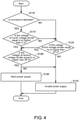
- FIG. 4 is a flowchart explaining the determination processing of the power supply state based on the connection status between the main arithmetic unit 10 and other units and a method for supplying power in accordance with the present embodiment.
- step S110 the state management circuit 110 of the main arithmetic unit 10 detects a connection status with other units.
- the connection status the following explains the connection with the power supply unit 30. However, the same explanation may apply to the connection with the power supply unit 30 and the secondary arithmetic unit 20.
- the state management circuit 110 determines that the power supply unit 30 exists and switches the control to step S115.
- the state management circuit 110 receives the detection signal of the voltage divided by the fourth voltage divider 102 via the signal line XP_PSPF, and in the case where the voltage of the received detection signal is equal to or higher than the predetermined voltage (5 V), the state management circuit 110 determines that the supply of power is valid (YES in step S115) and switches the control to step S120.
- the state management circuit 110 receives the detection signal of the voltage divided by the fourth voltage divider 102 via the signal line XP_PSPF, and in the case where the voltage of the received detection signal falls below the predetermined voltage (5 V) (lower than the voltage), the state management circuit 110 determines that the supply of power is invalid (NO in step S115) and switches the control to step S125.
- step S110 in the case where the power supply unit 30 is not connected to the main arithmetic unit 10, the voltage of the detection resistor 108 becomes the voltage (5 V) of the control voltage Vcc. In the case where a signal of the control voltage (e.g., 5 V) detected by the detection resistor 108 is received, the state management circuit 110 determines that the power supply unit 30 does not exist and switches the control to step S125.
- a signal of the control voltage e.g., 5 V
- step S125 when determining that the voltage input from the first voltage divider 104 falls below the predetermined threshold value (e.g., 24 V) (lower than the voltage) (NO in step S125), the state management circuit 110 switches the control to step S135.
- the predetermined threshold value e.g., 24 V
- the state management circuit 110 determines that no power is supplied from any of the first port 11 and the second port 12 and that the supply of power is invalid. When such a determination is made, the state management circuit 110 outputs, to the bus master part 190 via the signal line PSPF, the value (e.g., a Low signal) indicating that the supply of power from the power supply circuit 101 is invalid.
- the value e.g., a Low signal
- step S125 when determining that the voltage input from the first voltage divider 104 is equal to or higher than the predetermined threshold value (e.g., 24 V) (YES in step S125), the state management circuit 110 switches the control to step S120.
- the predetermined threshold value e.g., 24 V
- step S120 when determining that the voltage input from the second voltage divider 106 falls below the predetermined threshold value (e.g., 50 V) (lower than the voltage) (NO in step S120), the state management circuit 110 switches the control to step S135, and determines that the supply of power is invalid.
- the predetermined threshold value e.g., 50 V
- this determination is performed regardless of whether or not the power supply unit 30 is connected to the main arithmetic unit 10 (whether or not the power supply unit 30 exists). The reason is that, in the case where no electric charge is accumulated in the backup circuit, even if power is supplied to the power supply circuit 101 at the moment, when the supply of power is subsequently cut off, the main arithmetic unit 10 or the functional unit 40 or the like cannot perform the backup processing such as saving of data and so on.
- step S120 when determining that the voltage input from the second voltage divider 106 is equal to or higher than the predetermined threshold value (e.g., 50 V) (YES in step S120), the state management circuit 110 switches the control to step S130, and determines that the supply of power is valid. When such a determination is made, the state management circuit 110 outputs, to the bus master part 190 via the signal line PSPF, the value (e.g., a High signal) indicating that the supply of power from the power supply circuit 101 is valid. Accordingly, the main arithmetic unit 10 is capable of reliably detecting a power supply status.
- the predetermined threshold value e.g. 50 V
- FIG. 5 shows the correspondence table 380 relating to whether or not the main arithmetic unit 10 can be activated according to the power supply state in accordance with the present embodiment.
- the correspondence table 380 includes a PRSN item 381 relating to information transmitted to the signal line PRSN, an XP _PSPF item 382 relating to information transmitted to the signal line XP_PSPF, a 24V_PSPF item 383 relating to information transmitted to the signal line 24V_PSPF, a 50V_PSPF item 384 relating to information transmitted to the signal line 50V_PSPF, and an activation enable/disable item 385 relating to information of whether or not the main arithmetic unit 10 can be activated.
- the PRSN item 381 is an item indicating the presence or absence of connection with (the existence or non-existence of) the power supply unit 30 based on the voltage of the detection resistor 108. The following explains the existence or non-existence of the power supply unit 30, but the same explanation may apply to the existence or non-existence of the power supply unit 30 and the secondary arithmetic unit 20.
- the PRSN item 381 becomes "present” (the power supply unit 30 exists) in the case where the voltage of the detection resistor 108 becomes the voltage having the same potential as the ground, and becomes "absent” (the power supply unit 30 does not exist) in the case where the voltage of the detection resistor 108 becomes the control voltage (e.g., 5 V).
- the XP_PSPF item 382 is an item indicating whether or not power is supplied to the first port 11 based on the voltage of the fourth voltage divider 102. This item becomes “ ⁇ ” in the case where power is supplied, becomes “ ⁇ ” in the case where no power is supplied, and becomes “-” in both cases (whichever is applicable).
- the 24V_PSPF item 383 is an item indicating whether or not power is supplied to the second port 12 based on the voltage of the first voltage divider 104. This item becomes “ ⁇ ” in the case where power is supplied, becomes “ ⁇ ” in the case where no power is supplied, and becomes “-” in both cases (whichever is applicable).
- the 50V_PSPF item 384 is an item indicating whether or not electric charge is charged into the capacitor 125 based on the voltage of the second voltage divider 106. This item becomes “ ⁇ ” in the case where electric charge is charged, becomes “ ⁇ ” in the case where no electric charge is charged, and becomes “-” in both cases (whichever is applicable).
- the activation enable/disable item 385 is an item indicating whether or not the main arithmetic unit 10 can be activated. This item becomes “OK” in the case where the main arithmetic unit 10 can be activated, and becomes “NG” in the case where the main arithmetic unit 10 cannot be activated.
- the PRSN item 381 is "absent” is explained.
- the XP_PSPF item 382 since it is determined that the power supply unit 30 does not exist based on the voltage of the detection resistor 108, the XP_PSPF item 382 becomes "-".
- the reason that the XP_PSPF item 382 becomes "-" is that it includes the case where the power supply unit 30 is not connected and no power is supplied and the case where the power supply unit 30 is removed immediately before and the power supplied in the past remains. Since the PRSN item 381 is "absent", the supply of power by the power supply unit 30 is not performed.
- the 24V_PSPF item 383 is " ⁇ " and where it is “ ⁇ ” are explained.
- the activation enable/disable item 385 becomes "OK”. Since power is supplied from the second port 12 and electric charge is also charged into the capacitor 125, the main arithmetic unit 10 can be activated. The reason is that, in the case where the conditions of both the supply of power and the backup power are satisfied, the main arithmetic unit 10 can be activated, and even if the supply of power is cut off thereafter, the backup processing can be performed.
- the activation enable/disable item 385 becomes "NG".
- the main arithmetic unit 10 cannot be activated. The reason is that, even if power is currently being supplied, when the supply of power is subsequently cut off, it becomes impossible for the main arithmetic unit 10 to execute the processing for backup using the electric charge of the capacitor 125.
- the activation enable/disable item 385 becomes "NG". The reason is that, in the case where no power is supplied from the second port 12, even if the main arithmetic unit 10 can be temporarily activated using the electric charge of the capacitor 125, the subsequent power cannot be secured. When no electric charge is charged into the capacitor 125, the main arithmetic unit 10 cannot be activated.
- the supply of power by the power supply unit 30 is given priority.
- the supply of power from the second port 12 is indicated by "-". In this way, even if power is supplied from the second port 12, since power cannot be supplied to the secondary arithmetic unit 20 from the viewpoint of circuit configuration, both the case where the voltage is supplied from the second port 12 and the case where no voltage is supplied from the second port 12 are included (whichever is applicable).
- the PRSN item 381 is "present"
- the XP_PSPF item 382 is " ⁇ "
- the 24V_PSPF item 383 becomes “-”
- the 50V_PSPF item 384 is " ⁇ ”
- the activation enable/disable item 385 becomes "NG”. The reason is that, although the power supply unit 30 exists, since power is not supplied to the first port 11, even if electric charge is charged into the capacitor 125, the electric charge is reduced by being used for backup of the main arithmetic unit 10, and the main arithmetic unit 10 cannot be activated.
- the reason is that, although the power supply unit 30 exists, since power is not supplied to the first port 11, and moreover, no electric charge is charged into the capacitor 125 (there is also no electric charge which can be used for backup of the main arithmetic unit 10), the main arithmetic unit 10 cannot be activated.
- the main arithmetic unit 10 is capable of accurately determining the power supply state with respect to the main arithmetic unit 10 itself.
- the main arithmetic unit 10 sends the value indicating that supply of power is invalid to the bus master part 190 or the secondary arithmetic unit 20 via the signal line PSPF.
- the object to which the main arithmetic unit 10 sends the value indicating that the supply of power is invalid is not limited to the bus master part 190 but may be other units in embodiments not covered by the claimed invention.
- the information sent via the signal line PSPF may be sent by high and low voltages using a signal line that transmits and receives internal commands of the control apparatus 100.
- the value indicating that the supply of power is invalid which is sent by the state management circuit 110 to the bus master part 190, is sent from the arithmetic processing part 180 to the bus master part 190. That is, the arithmetic processing part 180 receives from the state management circuit 110 the value indicating that the supply of power is invalid, and information relating to the received value indicating that the supply of power is invalid is sent from the arithmetic processing part 180 to the bus master part 190.
Landscapes
- Engineering & Computer Science (AREA)
- Theoretical Computer Science (AREA)
- Physics & Mathematics (AREA)
- General Physics & Mathematics (AREA)
- General Engineering & Computer Science (AREA)
- Power Engineering (AREA)
- Automation & Control Theory (AREA)
- Power Sources (AREA)
- Programmable Controllers (AREA)
Claims (6)
- Arithmetische Einheit (10) für eine Steuervorrichtung (100) zum Steuern eines Steuerobjekts, wobei die arithmetische Einheit (10) geeignet ist, mit einer Funktionseinheit (40) verwendet zu werden, wobei die arithmetische Einheit (10) umfasst:einen arithmetischen Verarbeitungsabschnitt (180), der einen Prozessor (184) umfasst;einen Bushauptabschnitt (190), der mit dem arithmetischen Verarbeitungsabschnitt (180) verbunden ist und konfiguriert ist, eine Datenübertragung auf einem lokalen Bus (60) an die Funktionseinheit (40) zu managen; undeine Stromversorgungsschaltung (101), die konfiguriert ist, eine Leistung von außerhalb zu empfangen und eine Leistung an den arithmetischen Verarbeitungsabschnitt (180) und den Bushauptabschnitt (190) zu liefern, wobei die Stromversorgungsschaltung (101) umfasst:einen ersten Anschluss (11), der konfiguriert ist, Leistung von einer Stromversorgungseinheit (30), die in der Steuervorrichtung (100) enthalten ist, zu empfangen;einen zweiten Anschluss (12), der konfiguriert ist, Leistung von einer Stromversorgungsvorrichtung, die von der Stromversorgungseinheit (30) verschieden ist, zu empfangen;eine erste Spannungsumsetzungsschaltung (130) für eine Umsetzung in eine erste Spannung, die niedriger als eine Spannung ist, die an einem Verbindungsknoten (N4) zwischen dem ersten Anschluss (11) und dem zweiten Anschluss (12) erscheint,eine Reserveschaltung (120), die sowohl mit dem ersten Anschluss (11) als auch dem zweiten Anschluss (12) verbunden ist, wobei die Reserveschaltung (120) konfiguriert ist, den Bushauptabschnitt (190) mit Leistung zu versorgen und umfasst:eine dritte Spannungsumsetzungsschaltung (124), die zwischen dem ersten Anschluss (11) und dem zweiten Anschluss (12) und der ersten Spannungsumsetzungsschaltung (130) angeordnet ist und konfiguriert ist, Leistung, die von einer zweiten Spannungsumsetzungsschaltung (122) für eine Umsetzung in eine zweite Spannung, die höher als die erste Spannung ist, geliefert wird, in Leistung mit einer dritten Spannung, die niedriger als die zweite Spannung ist, umzusetzen; undeinen Kondensator (125), der zwischen der zweiten Spannungsumsetzungsschaltung (122) und der dritten Spannungsumsetzungsschaltung (124) angeschlossen ist und zumindest einen Teil der von der zweiten Spannungsumsetzungsschaltung (122) ausgegebenen Leistung speichern kann;eine Detektionsschaltung (108), die konfiguriert ist, das Vorhandensein der Stromversorgungseinheit (30) zu detektieren; undeine Zustandsmanagementschaltung (110), die konfiguriert ist, ein Zustandssignal auszugeben, dass angibt, ob die Stromversorgung von der Stromversorgungsschaltung (101) gültig ist oder nicht, wobei die Zustandsmanagementschaltung (110) konfiguriert ist, das Zustandssignal an den Bushauptabschnitt (190) über eine Signalleitung (PSPF) auszugeben, wenn die Stromversorgung von der Stromversorgungsschaltung (101) ungültig ist,wobei die Zustandsmanagementschaltung (110) konfiguriert ist, einen Wert des Zustandssignal s anhand einer Spannung des zweiten Anschlusses (12), einer Spannung des ersten Anschlusses (11) und eines Signals, das angibt, ob die Stromversorgungseinheit (30) vorhanden ist oder nicht, zu bestimmen,wobei die Funktionseinheit (40) das Abschalten der Stromversorgung durch Ausführen einer Verarbeitung mit einer höheren Priorität vor einer anderen Verarbeitung als Reaktion auf die Datenübertragung bezüglich des durch den Bushauptabschnitt (190) gemanagten Zustandssignals an die Funktionseinheit (40) vorbereiten kann, wobei die Datenübertragung Daten bezüglich des Abschaltens der Stromversorgung enthält.
- Arithmetische Einheit (10) nach Anspruch 1, wobei die Zustandsmanagementschaltung so konfiguriert ist, dass dann, wenn detektiert wird, dass die Stromversorgungseinheit (30) nicht vorhanden ist, wenn die Spannung des zweiten Anschlusses (12) unter einen vorgegebenen ersten Schwellenwert fällt, die Zustandsmanagementschaltung (100) als den Wert des Zustandssignals einen Wert ausgibt, der angibt, dass die Stromversorgung von der Stromversorgungsschaltung (101) ungültig ist.
- Arithmetische Einheit (10) nach Anspruch 1 oder 2, wobei die Zustandsmanagementschaltung so konfiguriert ist, dass ungeachtet dessen, ob die Stromversorgungseinheit (30) vorhanden ist oder nicht, die Zustandsmanagementschaltung (110) als den Wert des Zustandssignals einen Wert ausgibt, der angibt, dass die Stromversorgung von der Stromversorgungsschaltung (101) ungültig ist, wenn eine von der Reserveschaltung (120) ausgegebene Spannung unter einen vorgegebenen zweiten Schwellenwert fällt.
- Arithmetische Einheit (10) nach einem der Ansprüche 1 bis 3, wobeiein Signal bezüglich einer Spannung einer Leistung, die in die Stromversorgungseinheit (30) eingegeben wird, in die Zustandsmanagementschaltung (110) eingegeben wird und die Zustandsmanagementschaltung so konfiguriert ist, dass dann,wenn detektiert wird, dass die Stromversorgungseinheit (30) vorhanden ist, wenn die Spannung der Leistung, die in die Stromversorgungseinheit (30) eingegeben wird, unter einen vorgegebenen dritten Schwellenwert fällt, die Zustandsmanagementschaltung (110) als den Wert des Zustandssignals einen Wert ausgibt, der angibt, dass die Stromversorgung von der Stromversorgungsschaltung (101) ungültig ist.
- Arithmetische Einheit (10) nach einem der Ansprüche 1 bis 4, wobei die Stromversorgungsschaltung (101) ferner eine Blockierschaltung (14, 16) zum Verhindern, dass ein Strom zwischen dem ersten Anschluss (11) und dem zweiten Anschluss (12) fließt, umfasst.
- Arithmetische Einheit (10) nach einem der Ansprüche 1 bis 5, wobei die arithmetische Einheit (10) geeignet ist, mit einer sekundären arithmetischen Einheit (20) verwendet zu werden, die zwischen der Stromversorgungseinheit (30) und der arithmetischen Einheit (10) angeordnet ist; und
die Detektionsschaltung (108) konfiguriert ist, zusätzlich zu dem Vorhandensein der Stromversorgungseinheit (30) das Vorhandensein der sekundären arithmetischen Einheit (20) zu detektieren.
Applications Claiming Priority (1)
| Application Number | Priority Date | Filing Date | Title |
|---|---|---|---|
| JP2018044522A JP7176204B2 (ja) | 2018-03-12 | 2018-03-12 | 演算ユニット、および制御装置 |
Publications (2)
| Publication Number | Publication Date |
|---|---|
| EP3540562A1 EP3540562A1 (de) | 2019-09-18 |
| EP3540562B1 true EP3540562B1 (de) | 2022-02-09 |
Family
ID=64664605
Family Applications (1)
| Application Number | Title | Priority Date | Filing Date |
|---|---|---|---|
| EP18211460.3A Active EP3540562B1 (de) | 2018-03-12 | 2018-12-11 | Arithmetische einheit und steuerungsvorrichtung |
Country Status (4)
| Country | Link |
|---|---|
| US (1) | US10877538B2 (de) |
| EP (1) | EP3540562B1 (de) |
| JP (1) | JP7176204B2 (de) |
| CN (1) | CN110262298B (de) |
Families Citing this family (1)
| Publication number | Priority date | Publication date | Assignee | Title |
|---|---|---|---|---|
| JP6969585B2 (ja) * | 2019-03-29 | 2021-11-24 | オムロン株式会社 | マスタ装置、演算処理装置、プログラマブル・ロジック・コントローラ、ネットワーク、及び情報処理方法 |
Family Cites Families (21)
| Publication number | Priority date | Publication date | Assignee | Title |
|---|---|---|---|---|
| US4638175A (en) * | 1984-07-03 | 1987-01-20 | United Technologies Corporation | Electric power distribution and load transfer system |
| JP3047791B2 (ja) * | 1995-09-06 | 2000-06-05 | セイコーエプソン株式会社 | コンピューター |
| JP3145942B2 (ja) * | 1997-02-18 | 2001-03-12 | 日本電気株式会社 | 電源システム |
| JP4000722B2 (ja) * | 1999-02-23 | 2007-10-31 | 松下電工株式会社 | プログラマブルコントローラ |
| JP2006101684A (ja) * | 2004-09-03 | 2006-04-13 | Sony Corp | 電源回路および電子装置 |
| JP4851203B2 (ja) * | 2006-02-24 | 2012-01-11 | ルネサスエレクトロニクス株式会社 | 電源選択検出回路、及び電源制御方法 |
| JP5088490B2 (ja) | 2008-03-13 | 2012-12-05 | オムロン株式会社 | 二重化コントローラ |
| DE102008018871B4 (de) * | 2008-04-14 | 2010-10-07 | Atmel Automotive Gmbh | Empfängerschaltung, Verfahren zum Empfang eines Signals und Verwendung einer Detektionsschaltung und einer Kontrollschaltung |
| US8065562B2 (en) * | 2009-06-26 | 2011-11-22 | Seagate Technology Llc | Systems, methods and devices for backup power control in data storage devices |
| US8868957B2 (en) * | 2009-09-24 | 2014-10-21 | Xyratex Technology Limited | Auxiliary power supply, a method of providing power to a data storage system and a back-up power supply charging circuit |
| CN102053888A (zh) * | 2009-10-27 | 2011-05-11 | 英业达股份有限公司 | 运算装置的自我检测方法与系统 |
| US8638634B2 (en) * | 2011-03-01 | 2014-01-28 | Agiga Tech Inc. | Apparatus and method to measure energy capacity of a backup power supply without compromising power delivery |
| US11167367B2 (en) * | 2011-03-25 | 2021-11-09 | Illinois Tool Works Inc. | Welding power supply with controlled auxiliary power |
| KR101403087B1 (ko) * | 2011-12-27 | 2014-06-03 | 미쓰비시덴키 가부시키가이샤 | 전원 장치 |
| JP2014160377A (ja) * | 2013-02-20 | 2014-09-04 | Panasonic Industrial Devices Sunx Co Ltd | プログラマブルコントローラ |
| JP2014176153A (ja) * | 2013-03-07 | 2014-09-22 | Ricoh Co Ltd | 電気機器、電気機器の制御方法及びプログラム |
| JP6179344B2 (ja) * | 2013-10-24 | 2017-08-16 | 富士通株式会社 | 情報処理方法、プログラム、情報処理装置、及びコンピュータシステム |
| CN105993000B (zh) * | 2013-10-27 | 2021-05-07 | 超威半导体公司 | 用于浮点寄存器混叠的处理器和方法 |
| US9740258B2 (en) * | 2014-03-24 | 2017-08-22 | Intel Corporation | Hold-up energy storage and management |
| JP6458582B2 (ja) * | 2015-03-20 | 2019-01-30 | 富士ゼロックス株式会社 | 情報処理装置及び情報処理プログラム |
| US9760452B2 (en) * | 2015-08-06 | 2017-09-12 | International Business Machines Corporation | In-line backup power source incorporating communication capability |
-
2018
- 2018-03-12 JP JP2018044522A patent/JP7176204B2/ja active Active
- 2018-12-11 CN CN201811509677.2A patent/CN110262298B/zh active Active
- 2018-12-11 EP EP18211460.3A patent/EP3540562B1/de active Active
- 2018-12-17 US US16/221,633 patent/US10877538B2/en active Active
Non-Patent Citations (2)
| Title |
|---|
| LINEAR TECHNOLOGY: "LTC3350 High Current Supercapacitor Backup Controller and System Monitor", 1 August 2015 (2015-08-01), XP055709143, Retrieved from the Internet <URL:https://www.analog.com/media/en/technical-documentation/data-sheets/3350fc.pdf> [retrieved on 20200626] * |
| TEXAS INSTRUMENTS: "TIDA-00304-"Last Gasp" Hold Up Energy Storage Solution", 1 June 2014 (2014-06-01), XP055709261, Retrieved from the Internet <URL:https://www.ti.com/lit/ug/tidu506/tidu506.pdf?ts=1593442339112&ref_url=https%253A%252F%252Fwww.ti.com%252Ftool%252FTIDA-00304> [retrieved on 20200626] * |
Also Published As
| Publication number | Publication date |
|---|---|
| CN110262298A (zh) | 2019-09-20 |
| JP2019159703A (ja) | 2019-09-19 |
| US20190278351A1 (en) | 2019-09-12 |
| EP3540562A1 (de) | 2019-09-18 |
| CN110262298B (zh) | 2022-04-05 |
| JP7176204B2 (ja) | 2022-11-22 |
| US10877538B2 (en) | 2020-12-29 |
Similar Documents
| Publication | Publication Date | Title |
|---|---|---|
| EP1612910B1 (de) | Überwachungsschaltung für die bordeigene Stromversorgung und Leistungsversorgungssteuerung | |
| EP1612909B1 (de) | Integrierte Stromversorgungsschaltung mit Rückführungskreis | |
| JP2002517153A (ja) | 電源を制御するための方法および装置 | |
| CN103904959A (zh) | 多轴马达驱动系统和马达驱动设备 | |
| EP3540895B1 (de) | Steuerungsvorrichtung | |
| US20100214119A1 (en) | Method and device for assigning addresses in a system having a plurality of generator units positioned in parallel | |
| US5162623A (en) | Elevator monitor and control system with multiple power sources | |
| EP3540562B1 (de) | Arithmetische einheit und steuerungsvorrichtung | |
| JP2004531787A (ja) | 制御又は調節するためのシステム | |
| US7080273B2 (en) | Sequencing power supplies on daughter boards | |
| US11082004B2 (en) | Shutdown control system and method | |
| CN120295444A (zh) | 电源控制电路、侦测设备、反制设备和电子设备 | |
| CN114466481B (zh) | 一种检测led恒压驱动电源空载的电路及方法、led驱动器 | |
| EP0566996A2 (de) | Speicherprogrammierbare Steuerung mit einem Schaltkreis zur Vermeidung von falschen Eingaben | |
| CN115313801A (zh) | 用于域控制器的电源管理系统及方法 | |
| WO2023156209A1 (de) | Steuerung für ein haushaltsgerät | |
| US8566630B2 (en) | Apparatus, methods and computer program products supporting automatic network identification for power supplies | |
| CN100555127C (zh) | 自动化设备的外围组件 | |
| US10353448B2 (en) | Computer mainboard, voltage supply module and method for voltage supply of a computer mainboard | |
| CN113467283B (zh) | 一种电源控制电路及一种机器人 | |
| CN116742731B (zh) | 车载充电系统的控制方法、车载充电系统和车辆 | |
| CN113364246B (zh) | 一种晶闸管的驱动控制装置和方法 | |
| CN113439374A (zh) | 用于直流电压网的能量源、用于运行这种能量源的方法、具有多个这种能量源的直流电压网和用于运行这种直流电压网的方法 | |
| JP2885702B2 (ja) | 電源故障検出方式 | |
| CN117356008A (zh) | 供电控制装置及供电控制方法 |
Legal Events
| Date | Code | Title | Description |
|---|---|---|---|
| PUAI | Public reference made under article 153(3) epc to a published international application that has entered the european phase |
Free format text: ORIGINAL CODE: 0009012 |
|
| STAA | Information on the status of an ep patent application or granted ep patent |
Free format text: STATUS: REQUEST FOR EXAMINATION WAS MADE |
|
| 17P | Request for examination filed |
Effective date: 20181211 |
|
| AK | Designated contracting states |
Kind code of ref document: A1 Designated state(s): AL AT BE BG CH CY CZ DE DK EE ES FI FR GB GR HR HU IE IS IT LI LT LU LV MC MK MT NL NO PL PT RO RS SE SI SK SM TR |
|
| AX | Request for extension of the european patent |
Extension state: BA ME |
|
| RBV | Designated contracting states (corrected) |
Designated state(s): AL AT BE BG CH CY CZ DE DK EE ES FI FR GB GR HR HU IE IS IT LI LT LU LV MC MK MT NL NO PL PT RO RS SE SI SK SM TR |
|
| STAA | Information on the status of an ep patent application or granted ep patent |
Free format text: STATUS: EXAMINATION IS IN PROGRESS |
|
| 17Q | First examination report despatched |
Effective date: 20200707 |
|
| GRAP | Despatch of communication of intention to grant a patent |
Free format text: ORIGINAL CODE: EPIDOSNIGR1 |
|
| STAA | Information on the status of an ep patent application or granted ep patent |
Free format text: STATUS: GRANT OF PATENT IS INTENDED |
|
| INTG | Intention to grant announced |
Effective date: 20210929 |
|
| GRAS | Grant fee paid |
Free format text: ORIGINAL CODE: EPIDOSNIGR3 |
|
| GRAA | (expected) grant |
Free format text: ORIGINAL CODE: 0009210 |
|
| STAA | Information on the status of an ep patent application or granted ep patent |
Free format text: STATUS: THE PATENT HAS BEEN GRANTED |
|
| AK | Designated contracting states |
Kind code of ref document: B1 Designated state(s): AL AT BE BG CH CY CZ DE DK EE ES FI FR GB GR HR HU IE IS IT LI LT LU LV MC MK MT NL NO PL PT RO RS SE SI SK SM TR |
|
| REG | Reference to a national code |
Ref country code: GB Ref legal event code: FG4D |
|
| REG | Reference to a national code |
Ref country code: CH Ref legal event code: EP Ref country code: AT Ref legal event code: REF Ref document number: 1467907 Country of ref document: AT Kind code of ref document: T Effective date: 20220215 |
|
| REG | Reference to a national code |
Ref country code: IE Ref legal event code: FG4D |
|
| REG | Reference to a national code |
Ref country code: DE Ref legal event code: R096 Ref document number: 602018030535 Country of ref document: DE |
|
| REG | Reference to a national code |
Ref country code: LT Ref legal event code: MG9D |
|
| REG | Reference to a national code |
Ref country code: NL Ref legal event code: MP Effective date: 20220209 |
|
| REG | Reference to a national code |
Ref country code: AT Ref legal event code: MK05 Ref document number: 1467907 Country of ref document: AT Kind code of ref document: T Effective date: 20220209 |
|
| PG25 | Lapsed in a contracting state [announced via postgrant information from national office to epo] |
Ref country code: SE Free format text: LAPSE BECAUSE OF FAILURE TO SUBMIT A TRANSLATION OF THE DESCRIPTION OR TO PAY THE FEE WITHIN THE PRESCRIBED TIME-LIMIT Effective date: 20220209 Ref country code: RS Free format text: LAPSE BECAUSE OF FAILURE TO SUBMIT A TRANSLATION OF THE DESCRIPTION OR TO PAY THE FEE WITHIN THE PRESCRIBED TIME-LIMIT Effective date: 20220209 Ref country code: PT Free format text: LAPSE BECAUSE OF FAILURE TO SUBMIT A TRANSLATION OF THE DESCRIPTION OR TO PAY THE FEE WITHIN THE PRESCRIBED TIME-LIMIT Effective date: 20220609 Ref country code: NO Free format text: LAPSE BECAUSE OF FAILURE TO SUBMIT A TRANSLATION OF THE DESCRIPTION OR TO PAY THE FEE WITHIN THE PRESCRIBED TIME-LIMIT Effective date: 20220509 Ref country code: NL Free format text: LAPSE BECAUSE OF FAILURE TO SUBMIT A TRANSLATION OF THE DESCRIPTION OR TO PAY THE FEE WITHIN THE PRESCRIBED TIME-LIMIT Effective date: 20220209 Ref country code: LT Free format text: LAPSE BECAUSE OF FAILURE TO SUBMIT A TRANSLATION OF THE DESCRIPTION OR TO PAY THE FEE WITHIN THE PRESCRIBED TIME-LIMIT Effective date: 20220209 Ref country code: HR Free format text: LAPSE BECAUSE OF FAILURE TO SUBMIT A TRANSLATION OF THE DESCRIPTION OR TO PAY THE FEE WITHIN THE PRESCRIBED TIME-LIMIT Effective date: 20220209 Ref country code: ES Free format text: LAPSE BECAUSE OF FAILURE TO SUBMIT A TRANSLATION OF THE DESCRIPTION OR TO PAY THE FEE WITHIN THE PRESCRIBED TIME-LIMIT Effective date: 20220209 Ref country code: BG Free format text: LAPSE BECAUSE OF FAILURE TO SUBMIT A TRANSLATION OF THE DESCRIPTION OR TO PAY THE FEE WITHIN THE PRESCRIBED TIME-LIMIT Effective date: 20220509 |
|
| PG25 | Lapsed in a contracting state [announced via postgrant information from national office to epo] |
Ref country code: PL Free format text: LAPSE BECAUSE OF FAILURE TO SUBMIT A TRANSLATION OF THE DESCRIPTION OR TO PAY THE FEE WITHIN THE PRESCRIBED TIME-LIMIT Effective date: 20220209 Ref country code: LV Free format text: LAPSE BECAUSE OF FAILURE TO SUBMIT A TRANSLATION OF THE DESCRIPTION OR TO PAY THE FEE WITHIN THE PRESCRIBED TIME-LIMIT Effective date: 20220209 Ref country code: GR Free format text: LAPSE BECAUSE OF FAILURE TO SUBMIT A TRANSLATION OF THE DESCRIPTION OR TO PAY THE FEE WITHIN THE PRESCRIBED TIME-LIMIT Effective date: 20220510 Ref country code: FI Free format text: LAPSE BECAUSE OF FAILURE TO SUBMIT A TRANSLATION OF THE DESCRIPTION OR TO PAY THE FEE WITHIN THE PRESCRIBED TIME-LIMIT Effective date: 20220209 Ref country code: AT Free format text: LAPSE BECAUSE OF FAILURE TO SUBMIT A TRANSLATION OF THE DESCRIPTION OR TO PAY THE FEE WITHIN THE PRESCRIBED TIME-LIMIT Effective date: 20220209 |
|
| PG25 | Lapsed in a contracting state [announced via postgrant information from national office to epo] |
Ref country code: IS Free format text: LAPSE BECAUSE OF FAILURE TO SUBMIT A TRANSLATION OF THE DESCRIPTION OR TO PAY THE FEE WITHIN THE PRESCRIBED TIME-LIMIT Effective date: 20220609 |
|
| PG25 | Lapsed in a contracting state [announced via postgrant information from national office to epo] |
Ref country code: SM Free format text: LAPSE BECAUSE OF FAILURE TO SUBMIT A TRANSLATION OF THE DESCRIPTION OR TO PAY THE FEE WITHIN THE PRESCRIBED TIME-LIMIT Effective date: 20220209 Ref country code: SK Free format text: LAPSE BECAUSE OF FAILURE TO SUBMIT A TRANSLATION OF THE DESCRIPTION OR TO PAY THE FEE WITHIN THE PRESCRIBED TIME-LIMIT Effective date: 20220209 Ref country code: RO Free format text: LAPSE BECAUSE OF FAILURE TO SUBMIT A TRANSLATION OF THE DESCRIPTION OR TO PAY THE FEE WITHIN THE PRESCRIBED TIME-LIMIT Effective date: 20220209 Ref country code: EE Free format text: LAPSE BECAUSE OF FAILURE TO SUBMIT A TRANSLATION OF THE DESCRIPTION OR TO PAY THE FEE WITHIN THE PRESCRIBED TIME-LIMIT Effective date: 20220209 Ref country code: DK Free format text: LAPSE BECAUSE OF FAILURE TO SUBMIT A TRANSLATION OF THE DESCRIPTION OR TO PAY THE FEE WITHIN THE PRESCRIBED TIME-LIMIT Effective date: 20220209 Ref country code: CZ Free format text: LAPSE BECAUSE OF FAILURE TO SUBMIT A TRANSLATION OF THE DESCRIPTION OR TO PAY THE FEE WITHIN THE PRESCRIBED TIME-LIMIT Effective date: 20220209 |
|
| REG | Reference to a national code |
Ref country code: DE Ref legal event code: R097 Ref document number: 602018030535 Country of ref document: DE |
|
| PG25 | Lapsed in a contracting state [announced via postgrant information from national office to epo] |
Ref country code: AL Free format text: LAPSE BECAUSE OF FAILURE TO SUBMIT A TRANSLATION OF THE DESCRIPTION OR TO PAY THE FEE WITHIN THE PRESCRIBED TIME-LIMIT Effective date: 20220209 |
|
| PLBE | No opposition filed within time limit |
Free format text: ORIGINAL CODE: 0009261 |
|
| STAA | Information on the status of an ep patent application or granted ep patent |
Free format text: STATUS: NO OPPOSITION FILED WITHIN TIME LIMIT |
|
| 26N | No opposition filed |
Effective date: 20221110 |
|
| PG25 | Lapsed in a contracting state [announced via postgrant information from national office to epo] |
Ref country code: SI Free format text: LAPSE BECAUSE OF FAILURE TO SUBMIT A TRANSLATION OF THE DESCRIPTION OR TO PAY THE FEE WITHIN THE PRESCRIBED TIME-LIMIT Effective date: 20220209 |
|
| PG25 | Lapsed in a contracting state [announced via postgrant information from national office to epo] |
Ref country code: IT Free format text: LAPSE BECAUSE OF FAILURE TO SUBMIT A TRANSLATION OF THE DESCRIPTION OR TO PAY THE FEE WITHIN THE PRESCRIBED TIME-LIMIT Effective date: 20220209 |
|
| REG | Reference to a national code |
Ref country code: CH Ref legal event code: PL |
|
| GBPC | Gb: european patent ceased through non-payment of renewal fee |
Effective date: 20221211 |
|
| REG | Reference to a national code |
Ref country code: BE Ref legal event code: MM Effective date: 20221231 |
|
| PG25 | Lapsed in a contracting state [announced via postgrant information from national office to epo] |
Ref country code: LU Free format text: LAPSE BECAUSE OF NON-PAYMENT OF DUE FEES Effective date: 20221211 |
|
| PG25 | Lapsed in a contracting state [announced via postgrant information from national office to epo] |
Ref country code: LI Free format text: LAPSE BECAUSE OF NON-PAYMENT OF DUE FEES Effective date: 20221231 Ref country code: IE Free format text: LAPSE BECAUSE OF NON-PAYMENT OF DUE FEES Effective date: 20221211 Ref country code: GB Free format text: LAPSE BECAUSE OF NON-PAYMENT OF DUE FEES Effective date: 20221211 Ref country code: CH Free format text: LAPSE BECAUSE OF NON-PAYMENT OF DUE FEES Effective date: 20221231 |
|
| PG25 | Lapsed in a contracting state [announced via postgrant information from national office to epo] |
Ref country code: FR Free format text: LAPSE BECAUSE OF NON-PAYMENT OF DUE FEES Effective date: 20221231 Ref country code: BE Free format text: LAPSE BECAUSE OF NON-PAYMENT OF DUE FEES Effective date: 20221231 |
|
| PG25 | Lapsed in a contracting state [announced via postgrant information from national office to epo] |
Ref country code: HU Free format text: LAPSE BECAUSE OF FAILURE TO SUBMIT A TRANSLATION OF THE DESCRIPTION OR TO PAY THE FEE WITHIN THE PRESCRIBED TIME-LIMIT; INVALID AB INITIO Effective date: 20181211 |
|
| PG25 | Lapsed in a contracting state [announced via postgrant information from national office to epo] |
Ref country code: CY Free format text: LAPSE BECAUSE OF FAILURE TO SUBMIT A TRANSLATION OF THE DESCRIPTION OR TO PAY THE FEE WITHIN THE PRESCRIBED TIME-LIMIT Effective date: 20220209 |
|
| PG25 | Lapsed in a contracting state [announced via postgrant information from national office to epo] |
Ref country code: MK Free format text: LAPSE BECAUSE OF FAILURE TO SUBMIT A TRANSLATION OF THE DESCRIPTION OR TO PAY THE FEE WITHIN THE PRESCRIBED TIME-LIMIT Effective date: 20220209 |
|
| PG25 | Lapsed in a contracting state [announced via postgrant information from national office to epo] |
Ref country code: MC Free format text: LAPSE BECAUSE OF FAILURE TO SUBMIT A TRANSLATION OF THE DESCRIPTION OR TO PAY THE FEE WITHIN THE PRESCRIBED TIME-LIMIT Effective date: 20220209 |
|
| PG25 | Lapsed in a contracting state [announced via postgrant information from national office to epo] |
Ref country code: TR Free format text: LAPSE BECAUSE OF FAILURE TO SUBMIT A TRANSLATION OF THE DESCRIPTION OR TO PAY THE FEE WITHIN THE PRESCRIBED TIME-LIMIT Effective date: 20220209 Ref country code: MC Free format text: LAPSE BECAUSE OF FAILURE TO SUBMIT A TRANSLATION OF THE DESCRIPTION OR TO PAY THE FEE WITHIN THE PRESCRIBED TIME-LIMIT Effective date: 20220209 |
|
| PG25 | Lapsed in a contracting state [announced via postgrant information from national office to epo] |
Ref country code: MT Free format text: LAPSE BECAUSE OF FAILURE TO SUBMIT A TRANSLATION OF THE DESCRIPTION OR TO PAY THE FEE WITHIN THE PRESCRIBED TIME-LIMIT Effective date: 20220209 |
|
| PGFP | Annual fee paid to national office [announced via postgrant information from national office to epo] |
Ref country code: DE Payment date: 20241216 Year of fee payment: 7 |