EP3540297A1 - Fahrzeugscheinwerfer - Google Patents
Fahrzeugscheinwerfer Download PDFInfo
- Publication number
- EP3540297A1 EP3540297A1 EP19160839.7A EP19160839A EP3540297A1 EP 3540297 A1 EP3540297 A1 EP 3540297A1 EP 19160839 A EP19160839 A EP 19160839A EP 3540297 A1 EP3540297 A1 EP 3540297A1
- Authority
- EP
- European Patent Office
- Prior art keywords
- reflector
- openings
- vehicle headlight
- carrier plate
- projections
- Prior art date
- Legal status (The legal status is an assumption and is not a legal conclusion. Google has not performed a legal analysis and makes no representation as to the accuracy of the status listed.)
- Granted
Links
Images

Classifications
-
- F—MECHANICAL ENGINEERING; LIGHTING; HEATING; WEAPONS; BLASTING
- F21—LIGHTING
- F21S—NON-PORTABLE LIGHTING DEVICES; SYSTEMS THEREOF; VEHICLE LIGHTING DEVICES SPECIALLY ADAPTED FOR VEHICLE EXTERIORS
- F21S45/00—Arrangements within vehicle lighting devices specially adapted for vehicle exteriors, for purposes other than emission or distribution of light
- F21S45/40—Cooling of lighting devices
- F21S45/47—Passive cooling, e.g. using fins, thermal conductive elements or openings
-
- B—PERFORMING OPERATIONS; TRANSPORTING
- B60—VEHICLES IN GENERAL
- B60Q—ARRANGEMENT OF SIGNALLING OR LIGHTING DEVICES, THE MOUNTING OR SUPPORTING THEREOF OR CIRCUITS THEREFOR, FOR VEHICLES IN GENERAL
- B60Q1/00—Arrangement of optical signalling or lighting devices, the mounting or supporting thereof or circuits therefor
- B60Q1/02—Arrangement of optical signalling or lighting devices, the mounting or supporting thereof or circuits therefor the devices being primarily intended to illuminate the way ahead or to illuminate other areas of way or environments
- B60Q1/04—Arrangement of optical signalling or lighting devices, the mounting or supporting thereof or circuits therefor the devices being primarily intended to illuminate the way ahead or to illuminate other areas of way or environments the devices being headlights
- B60Q1/0408—Arrangement of optical signalling or lighting devices, the mounting or supporting thereof or circuits therefor the devices being primarily intended to illuminate the way ahead or to illuminate other areas of way or environments the devices being headlights built into the vehicle body, e.g. details concerning the mounting of the headlamps on the vehicle body
-
- F—MECHANICAL ENGINEERING; LIGHTING; HEATING; WEAPONS; BLASTING
- F21—LIGHTING
- F21S—NON-PORTABLE LIGHTING DEVICES; SYSTEMS THEREOF; VEHICLE LIGHTING DEVICES SPECIALLY ADAPTED FOR VEHICLE EXTERIORS
- F21S41/00—Illuminating devices specially adapted for vehicle exteriors, e.g. headlamps
- F21S41/10—Illuminating devices specially adapted for vehicle exteriors, e.g. headlamps characterised by the light source
- F21S41/14—Illuminating devices specially adapted for vehicle exteriors, e.g. headlamps characterised by the light source characterised by the type of light source
- F21S41/141—Light emitting diodes [LED]
- F21S41/147—Light emitting diodes [LED] the main emission direction of the LED being angled to the optical axis of the illuminating device
- F21S41/148—Light emitting diodes [LED] the main emission direction of the LED being angled to the optical axis of the illuminating device the main emission direction of the LED being perpendicular to the optical axis
-
- F—MECHANICAL ENGINEERING; LIGHTING; HEATING; WEAPONS; BLASTING
- F21—LIGHTING
- F21S—NON-PORTABLE LIGHTING DEVICES; SYSTEMS THEREOF; VEHICLE LIGHTING DEVICES SPECIALLY ADAPTED FOR VEHICLE EXTERIORS
- F21S41/00—Illuminating devices specially adapted for vehicle exteriors, e.g. headlamps
- F21S41/10—Illuminating devices specially adapted for vehicle exteriors, e.g. headlamps characterised by the light source
- F21S41/19—Attachment of light sources or lamp holders
- F21S41/192—Details of lamp holders, terminals or connectors
-
- F—MECHANICAL ENGINEERING; LIGHTING; HEATING; WEAPONS; BLASTING
- F21—LIGHTING
- F21S—NON-PORTABLE LIGHTING DEVICES; SYSTEMS THEREOF; VEHICLE LIGHTING DEVICES SPECIALLY ADAPTED FOR VEHICLE EXTERIORS
- F21S41/00—Illuminating devices specially adapted for vehicle exteriors, e.g. headlamps
- F21S41/30—Illuminating devices specially adapted for vehicle exteriors, e.g. headlamps characterised by reflectors
-
- F—MECHANICAL ENGINEERING; LIGHTING; HEATING; WEAPONS; BLASTING
- F21—LIGHTING
- F21S—NON-PORTABLE LIGHTING DEVICES; SYSTEMS THEREOF; VEHICLE LIGHTING DEVICES SPECIALLY ADAPTED FOR VEHICLE EXTERIORS
- F21S41/00—Illuminating devices specially adapted for vehicle exteriors, e.g. headlamps
- F21S41/30—Illuminating devices specially adapted for vehicle exteriors, e.g. headlamps characterised by reflectors
- F21S41/32—Optical layout thereof
- F21S41/33—Multi-surface reflectors, e.g. reflectors with facets or reflectors with portions of different curvature
- F21S41/334—Multi-surface reflectors, e.g. reflectors with facets or reflectors with portions of different curvature the reflector consisting of patch like sectors
- F21S41/336—Multi-surface reflectors, e.g. reflectors with facets or reflectors with portions of different curvature the reflector consisting of patch like sectors with discontinuity at the junction between adjacent areas
-
- F—MECHANICAL ENGINEERING; LIGHTING; HEATING; WEAPONS; BLASTING
- F21—LIGHTING
- F21S—NON-PORTABLE LIGHTING DEVICES; SYSTEMS THEREOF; VEHICLE LIGHTING DEVICES SPECIALLY ADAPTED FOR VEHICLE EXTERIORS
- F21S41/00—Illuminating devices specially adapted for vehicle exteriors, e.g. headlamps
- F21S41/30—Illuminating devices specially adapted for vehicle exteriors, e.g. headlamps characterised by reflectors
- F21S41/39—Attachment thereof
-
- F—MECHANICAL ENGINEERING; LIGHTING; HEATING; WEAPONS; BLASTING
- F21—LIGHTING
- F21S—NON-PORTABLE LIGHTING DEVICES; SYSTEMS THEREOF; VEHICLE LIGHTING DEVICES SPECIALLY ADAPTED FOR VEHICLE EXTERIORS
- F21S45/00—Arrangements within vehicle lighting devices specially adapted for vehicle exteriors, for purposes other than emission or distribution of light
- F21S45/40—Cooling of lighting devices
- F21S45/49—Attachment of the cooling means
-
- F—MECHANICAL ENGINEERING; LIGHTING; HEATING; WEAPONS; BLASTING
- F21—LIGHTING
- F21V—FUNCTIONAL FEATURES OR DETAILS OF LIGHTING DEVICES OR SYSTEMS THEREOF; STRUCTURAL COMBINATIONS OF LIGHTING DEVICES WITH OTHER ARTICLES, NOT OTHERWISE PROVIDED FOR
- F21V17/00—Fastening of component parts of lighting devices, e.g. shades, globes, refractors, reflectors, filters, screens, grids or protective cages
- F21V17/10—Fastening of component parts of lighting devices, e.g. shades, globes, refractors, reflectors, filters, screens, grids or protective cages characterised by specific fastening means or way of fastening
-
- F—MECHANICAL ENGINEERING; LIGHTING; HEATING; WEAPONS; BLASTING
- F21—LIGHTING
- F21V—FUNCTIONAL FEATURES OR DETAILS OF LIGHTING DEVICES OR SYSTEMS THEREOF; STRUCTURAL COMBINATIONS OF LIGHTING DEVICES WITH OTHER ARTICLES, NOT OTHERWISE PROVIDED FOR
- F21V17/00—Fastening of component parts of lighting devices, e.g. shades, globes, refractors, reflectors, filters, screens, grids or protective cages
- F21V17/10—Fastening of component parts of lighting devices, e.g. shades, globes, refractors, reflectors, filters, screens, grids or protective cages characterised by specific fastening means or way of fastening
- F21V17/12—Fastening of component parts of lighting devices, e.g. shades, globes, refractors, reflectors, filters, screens, grids or protective cages characterised by specific fastening means or way of fastening by screwing
-
- F—MECHANICAL ENGINEERING; LIGHTING; HEATING; WEAPONS; BLASTING
- F21—LIGHTING
- F21V—FUNCTIONAL FEATURES OR DETAILS OF LIGHTING DEVICES OR SYSTEMS THEREOF; STRUCTURAL COMBINATIONS OF LIGHTING DEVICES WITH OTHER ARTICLES, NOT OTHERWISE PROVIDED FOR
- F21V23/00—Arrangement of electric circuit elements in or on lighting devices
-
- F—MECHANICAL ENGINEERING; LIGHTING; HEATING; WEAPONS; BLASTING
- F21—LIGHTING
- F21W—INDEXING SCHEME ASSOCIATED WITH SUBCLASSES F21K, F21L, F21S and F21V, RELATING TO USES OR APPLICATIONS OF LIGHTING DEVICES OR SYSTEMS
- F21W2107/00—Use or application of lighting devices on or in particular types of vehicles
- F21W2107/10—Use or application of lighting devices on or in particular types of vehicles for land vehicles
-
- F—MECHANICAL ENGINEERING; LIGHTING; HEATING; WEAPONS; BLASTING
- F21—LIGHTING
- F21Y—INDEXING SCHEME ASSOCIATED WITH SUBCLASSES F21K, F21L, F21S and F21V, RELATING TO THE FORM OR THE KIND OF THE LIGHT SOURCES OR OF THE COLOUR OF THE LIGHT EMITTED
- F21Y2115/00—Light-generating elements of semiconductor light sources
- F21Y2115/10—Light-emitting diodes [LED]
Definitions
- the invention relates to a vehicle headlamp with at least one light source, preferably an LED and a reflector, which are arranged on a common carrier plate.
- LEDs and associated reflectors which provide the precise light beam steering of the LEDs.
- the LEDs and the associated reflectors are mounted on a common carrier plate, preferably a printed circuit board.
- the relative position between the LED and the reflector is crucial in ensuring that the illumination of the street complies with legal requirements. There are thus high requirements to meet both the manufacturing tolerances of the components as well as the tolerances in the positioning of the components on the carrier plate. Even small tolerance violations can lead to significant loss of light and / or no longer legally compliant light distribution on the road.
- a headlamp module has been proposed in which the lighting unit is rotatably fixed to a heat sink.
- slots are provided in the support plate and in the heat sink for a screw connection, which allow an adjustment of the relative position of the components to each other.
- the possibility is created to compensate for tolerance overruns in the component production by adjusting the component positions.
- the assembly of the components is quite expensive.
- the present invention has for its object to provide a vehicle headlamp with high illumination precision, which is easy to install.
- a vehicle headlamp having at least one light source, preferably an LED and a reflector, which are arranged on a common carrier plate, which is characterized in that projections are arranged on the reflector, which are connected by means of a press fit with openings in the carrier plate ,
- the carrier plate and the reflector are connected to each other without clearance over all tolerance ranges.
- the overall tolerance of the tolerance chain formed from the component tolerances and the positioning tolerances of the optical system of the headlight can be reduced. This leads to an increase in the quality of the headlamp and lower reject rates during production. This can costly adjustments of the reflector on the support plate omitted.
- the press fit ensures automatic tolerance compensation during assembly.
- a single tolerance of the optical system of the headlamp can be increased with the same overall headlamp tolerance.
- a single tolerance of the optical system of the headlamp can be dispensed with a precision assembly of the LED on the carrier plate and replaced by a standard equipment, which can realize significant cost savings.
- the projections of the reflector may be disposed on the periphery of mounting holes on the reflector.
- further fastening means in particular screws can be passed through the mounting holes of the reflector to fix the reflector to the support plate.
- glue it is also possible to glue the reflector to the carrier plate.
- screws are used as additional fastening means, they can be passed through the openings in the carrier plate and bolted to a heat sink arranged on the rear side of the carrier plate.
- the light sources commonly used for newer vehicle headlights are high-performance SMD LEDs, which are soldered directly to a printed circuit board that simultaneously forms the carrier plate for the reflector. The power loss of these LEDs must be dissipated to avoid thermal damage to the LEDs. For this reason, the carrier plate is usually directly on a heat sink. With the help of screws can be a firm interconnected unit from the support plate, the heat sink and the reflector manufacture.
- the openings in the carrier plate may preferably have a round cross-section with a larger diameter than the screw diameter. They are thus able to accommodate the projections of the reflector and the screws.
- the reflector is provided per opening in the support plate with two circular arc-shaped projections. These projections may also be formed tab-shaped. When inserted into the openings in the carrier plate, the projections can therefore be pressed radially inward and produce the required interference fit with the opening edges in the carrier plate due to their elasticity.
- the projections may preferably be made of an elastic material, preferably of a thermoplastic. These relatively soft projections together with a corresponding shape ensure that the interference fit between reflector and carrier plate can be produced without having to spend too high assembly forces, which in turn would lead to component overloads or a delay, in particular the carrier plate. It has been shown that the material elasticity of such projections for tolerance compensation by means of a press fit can also be used in a highly distortion-sensitive optical system such as a vehicle headlight.
- two openings for fixing the reflector may be provided in the support plate in order to mount it against rotation on the support plate can.
- the at least one LED can be arranged on a central axis between the two openings on the carrier plate, so that the positions of the openings and the position of the at least one LED form an isosceles triangle.
- the exploded view Fig. 1 shows a lighting unit 10 of a vehicle headlight otherwise not shown.
- the illumination unit 10 has a carrier plate 11 in the form of a printed circuit board with a LED 12 soldered onto it as a light source, a reflector 13 and a heat sink 14.
- the support plate 11 is provided with two openings 15 for receiving fastening screws 16 for the reflector 13.
- the reflector 13 is screwed by means of screws 16 to the heat sink 14.
- the reflector 13 has two mounting holes 18 for the fastening screws 16.
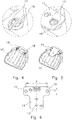
- the two arcuate and tab-shaped projections 17 are arranged, which are insertable into the openings 15 of the support plate, such as Fig. 5 clarified.
- the projections 17 are preferably made of a soft, elastic material so that they can yield radially inwardly during insertion into the openings 15 of the support plate 11 so that the interference fit with the openings 15 can be produced without excessive assembly forces.
- Fig. 6 schematically illustrates the on the carrier plate 11 with respect to the light source 12 aufummierenden mounting tolerances A and B, where A is the tolerance of the mutual distance x of the two openings 15 and B, the tolerance of the diameter y of the openings 15.
- the LED 12 is arranged on a central axis between the openings 15. Their position thus forms together with the positions of the openings 15, the vertices of an isosceles triangle.
Landscapes
- Engineering & Computer Science (AREA)
- General Engineering & Computer Science (AREA)
- Mechanical Engineering (AREA)
- Physics & Mathematics (AREA)
- Microelectronics & Electronic Packaging (AREA)
- Optics & Photonics (AREA)
- Non-Portable Lighting Devices Or Systems Thereof (AREA)
Abstract
Description
- Die Erfindung betrifft einen Fahrzeugscheinwerfer mit mindestens einer Lichtquelle, vorzugsweise einer LED und einem Reflektor, die auf einer gemeinsamen Trägerplatte angeordnet sind.
- Moderne Fahrzeugscheinwerfer sind aufgrund der besseren Beleuchtungsergebnisse, eines geringeren Energieverbrauchs und eines modernen Designs zunehmend mit LEDs ausgestattet. Je nach Anzahl der verschiedenen zur erfüllenden Beleuchtungsfunktionen wie Abblendlicht, Fernlicht, Standlicht etc. sind eine oder mehrere LEDs und diesen zugeordneten Reflektoren, die für die genaue Lichtstrahllenkung der LEDs sorgen, vorgesehen. Die LEDs und die zugehörigen Reflektoren sind dabei auf einer gemeinsamen Trägerplatte, vorzugsweise einer Leiterplatte montiert. Die relative Position zwischen LED und Reflektor ist dabei entscheidend dafür, dass die Ausleuchtung der Straße den gesetzlichen Vorgaben entspricht. Es sind somit hohe Anforderungen sowohl an die Fertigungstoleranzen der Bauteile als auch an die Toleranzen bei der Positionierung der Bauteile auf der Trägerplatte zu erfüllen. Schon geringe Toleranzüberschreitungen können zu markanten Lichteinbußen und/oder nicht mehr gesetzeskonformen Lichtverteilungen auf der Straße führen.
- In der
WO 2014/138763 A1 wurde daher ein Scheinwerfermodul vorgeschlagen, bei dem die Leuchteinheit drehbar an einem Kühlkörper festgelegt ist. Außerdem sind Langlöcher in der Trägerplatine und im Kühlkörper für eine Schraubverbindung vorgesehen, die eine Justierung der relativen Position der Bauteile zueinander erlauben. Über das Vorsehen von Lagerspielen zwischen den Bauteilen wird daher die Möglichkeit geschaffen, Toleranzüberschreitungen bei der Bauteilfertigung durch ein Justieren der Bauteilpositionen auszugleichen. Die Montage der Bauteile gestaltet sich dadurch jedoch recht aufwändig. - Der vorliegenden Erfindung liegt die Aufgabe zugrunde, einen Fahrzeugscheinwerfer mit hoher Beleuchtungspräzision bereitzustellen, der rasch zu montieren ist.
- Die Aufgabe wird gelöst durch einen Fahrzeugscheinwerfer mit mindestens einer Lichtquelle, vorzugsweise einer LED und einem Reflektor, die auf einer gemeinsamen Trägerplatte angeordnet sind, der dadurch gekennzeichnet ist, dass am Reflektor Vorsprünge angeordnet sind, die mittels einer Presspassung mit Öffnungen in der Trägerplatte verbunden sind.
- Durch die Presspassung zwischen den Reflektorvorsprüngen und den Öffnungen der Trägerplatte sind die Trägerplatte und der Reflektor über alle Toleranzbereiche spielfrei miteinander verbunden. Dadurch kann die Gesamttoleranz der aus den Bauteiltoleranzen und den Positioniertoleranzen des optischen Systems des Scheinwerfers gebildeten Toleranzkette reduziert werden. Dies führt zu einer Qualitätssteigerung des Scheinwerfers sowie zu geringeren Ausschussraten bei der Fertigung. Dabei können aufwändige Justierungen des Reflektors auf der Trägerplatte entfallen. Die Presspassung sorgt für einen automatischen Toleranzausgleich bei der Montage.
- Alternativ kann bei gleichbleibender Gesamttoleranz des Scheinwerfers eine Einzeltoleranz des optischen Systems des Scheinwerfers erhöht werden. So kann beispielsweise auf eine Präzisionsbestückung der LED auf der Trägerplatte verzichtet und durch eine Normalbestückung ersetzt werden, wodurch sich deutliche Kosteneinsparungen realisieren lassen.
- Für die Art und Form der Vorsprünge des Reflektors sind verschiedene Lösungen denkbar. Bei einer bevorzugten Ausführungsform des Fahrzeugscheinwerfers können die Vorsprünge am Umfang von Befestigungslöchern am Reflektor angeordnet sein. Zusätzlich zur Verbindung über die Presspassungen können durch die Befestigungslöcher des Reflektors weitere Befestigungsmittel, insbesondere Schrauben hindurchgeführt werden, um den Reflektor an der Trägerplatte festzulegen. Selbstverständlich besteht jedoch auch die Möglichkeit, den Reflektor auf die Trägerplatte aufzukleben.
- Werden Schrauben als zusätzliche Befestigungsmittel verwendet, so können diese durch die Öffnungen in der Trägerplatte hindurchgeführt und mit einem auf der Rückseite der Trägerplatte angeordneten Kühlkörper verschraubt sein. Bei den für neuere Fahrzeugscheinwerfer üblicherweise eingesetzten Lichtquellen handelt es sich um Hochleistungs-SMD-LEDs, die direkt auf eine Leiterplatte, die gleichzeitig die Trägerplatte für den Reflektor bildet, aufgelötet sind. Die Verlustleistung dieser LEDs muss abgeführt werden, um eine thermische Beschädigung der LEDs zu vermeiden. Aus diesem Grund liegt die Trägerplatte in der Regel direkt auf einem Kühlkörper auf. Mit Hilfe der Schrauben lässt sich eine fest miteinander verbundene Einheit aus der Trägerplatte, dem Kühlkörper und dem Reflektor herstellen.
- Dabei können die Öffnungen in der Trägerplatte vorzugsweise einen runden Querschnitt mit einem größeren Durchmesser als der Schraubendurchmesser aufweisen. Sie sind damit in der Lage, die Vorsprünge des Reflektors und die Schrauben aufzunehmen.
- Weitere Vorteile ergeben sich, wenn der Reflektor je Öffnung in der Trägerplatte mit zwei kreisbogenförmigen Vorsprüngen versehen ist. Diese Vorsprünge können zudem laschenförmig ausgebildet sein. Beim Einführen in die Öffnungen in der Trägerplatte können die Vorsprünge daher radial nach innen gedrückt werden und aufgrund ihrer Elastizität die erforderliche Presspassung mit den Öffnungsrändern in der Trägerplatte herstellen.
- Die Vorsprünge können bevorzugt aus einem elastischen Werkstoff, vorzugsweise aus einem Thermoplast gefertigt sein. Diese relativ weichen Vorsprünge sorgen zusammen mit einer entsprechenden Formgebung dafür, dass die Presspassung zwischen Reflektor und Trägerplatte hergestellt werden kann, ohne zu hohe Montagekräfte aufwenden zu müssen, die wiederum zu Bauteilüberlastungen oder einem Verzug insbesondere der Trägerplatte führen würden. Es hat sich gezeigt, dass die Werkstoffelastizität solcher Vorsprünge zum Toleranzausgleich mittels einer Presspassung auch bei einem stark verzugssensiblen optischen System wie einem Fahrzeugscheinwerfer eingesetzt werden kann.
- Zweckmäßigerweise können in der Trägerplatte zwei Öffnungen zur Befestigung des Reflektors vorgesehen sein, um diesen verdrehsicher auf der Trägerplatte montieren zu können.
- Die mindestens eine LED kann dabei auf einer Mittelachse zwischen den beiden Öffnungen auf der Trägerplatte angeordnet sein, sodass die Positionen der Öffnungen und die Position der mindestens einen LED ein gleichschenkliges Dreieck bilden.
- Nachfolgend wird ein bevorzugtes Ausführungsbeispiel einer Beleuchtungseinheit eines erfindungsgemäßen Fahrzeugscheinwerfers mit Bezug auf die Zeichnung näher beschrieben.
- Dabei zeigen:
- Fig. 1
- eine Explosionsdarstellung einer Beleuchtungseinheit eines erfindungsgemäßen Fahrzeugscheinwerfers;
- Fig. 2
- eine Draufsicht auf die Beleuchtungseinheit aus
Fig. 1 ; - Fig. 3
- einen Teilschnitt durch die Beleuchtungseinheit entlang der Linie A-A in
Fig. 2 ; - Fig. 4
- eine Ansicht von unten auf einen Reflektor der Beleuchtungseinheit aus
Fig. 1 mit einer vergrößerten Detaildarstellung; - Fig. 5
- eine Ansicht von unten auf den Reflektor und eine Trägerplatte der Beleuchtungseinheit aus
Fig. 1 zusammen mit einer vergrößerten Detaildarstellung; - Fig. 6
- eine Draufsicht auf die Trägerplatte der Beleuchtungseinheit aus
Fig. 1 . - Die Explosionsdarstellung aus
Fig. 1 zeigt eine Beleuchtungseinheit 10 eines ansonsten nicht weiter dargestellten Fahrzeugscheinwerfers. Die Beleuchtungseinheit 10 weist eine Trägerplatte 11 in Form einer Leiterplatte mit einer darauf aufgelöteten LED 12 als Lichtquelle, einen Reflektor 13 sowie einen Kühlkörper 14 auf. Die Trägerplatte 11 ist mit zwei Öffnungen 15 zur Aufnahme von Befestigungsschrauben 16 für den Reflektor 13 versehen. Wie die Draufsicht auf die Beleuchtungseinheit 10 und insbesondere die Schnittdarstellung ausFig. 3 verdeutlichen, wird der Reflektor 13 mit Hilfe der Schrauben 16 mit dem Kühlkörper 14 verschraubt. Mit der Trägerplatte 11 ist der Reflektor 13 dagegen mittels einer Presspassung verbunden, die je Öffnung 15 in der Trägerplatte 11 von zwei Vorsprüngen 17 gebildet wird, wieFig. 3 und noch deutlicher dieFiguren 4 und 5 zeigen. - Aus der Ansicht von unten auf den Reflektor 13 in
Fig. 4 ist zu erkennen, dass der Reflektor 13 zwei Befestigungslöcher 18 für die Befestigungsschrauben 16 aufweist. Am äußeren Rand der Befestigungslöcher 18 sind die beiden kreisbogen- und laschenförmigen Vorsprünge 17 angeordnet, die in die Öffnungen 15 der Trägerplatte einführbar sind, wieFig. 5 verdeutlicht. Die Vorsprünge 17 sind vorzugsweise aus einem weichen, elastischen Werkstoff gefertigt, sodass sie beim Einführen in die Öffnungen 15 der Trägerplatte 11 radial nach innen nachgeben können, damit die Presspassung mit den Öffnungen 15 ohne zu große Montagekräfte herstellbar ist. -
Fig. 6 verdeutlicht schematisch die auf der Trägerplatte 11 sich bezüglich der Lichtquelle 12 aufsummierenden Bestückungstoleranzen A und B, wobei A die Toleranz des gegenseitigen Abstands x der beiden Öffnungen 15 und B die Toleranz des Durchmessers y der Öffnungen 15 ist. Durch die Presspassung zwischen dem Reflektor 13 und der Trägerplatte 11 können Toleranzüberschreitungen der Toleranzen A und B teilweise ausgeglichen werden. - Die LED 12 ist auf einer Mittelachse zwischen den Öffnungen 15 angeordnet. Ihre Position bildet somit zusammen mit den Positionen der Öffnungen 15 die Eckpunkte eines gleichschenkligen Dreiecks.
Claims (10)
- Fahrzeugscheinwerfer mit mindestens einer Lichtquelle (12), vorzugsweise einer LED und einem Reflektor (13), die auf einer gemeinsamen Trägerplatte (11) angeordnet sind, dadurch gekennzeichnet, dass am Reflektor (13) Vorsprünge (17) angeordnet sind, die mittels einer Presspassung mit Öffnungen (15) in der Trägerplatte (11) verbunden sind.
- Fahrzeugscheinwerfer nach Anspruch 1, dadurch gekennzeichnet, dass die Vorsprünge (17) am Umfang von Befestigungslöchern (18) am Reflektor (13) angeordnet sind.
- Fahrzeugscheinwerfer nach Anspruch 2, dadurch gekennzeichnet, dass durch die Befestigungslöcher (18) des Reflektors (13) Schrauben (16) hindurchgeführt sind.
- Fahrzeugscheinwerfer nach Anspruch 3, dadurch gekennzeichnet, dass die Schrauben (16) durch die Öffnungen (15) in der Trägerplatte (11) hindurchgeführt und mit einem auf der Rückseite der Trägerplatte (11) angeordneten Kühlkörper (14) verschraubt sind.
- Fahrzeugscheinwerfer nach Anspruch 3 oder 4, dadurch gekennzeichnet, dass die Öffnungen (15) in der Trägerplatte (11) einen runden Querschnitt mit einem größeren Durchmesser als der Schraubendurchmesser aufweisen.
- Fahrzeugscheinwerfer nach einem der vorhergehenden Ansprüche, dadurch gekennzeichnet, dass der Reflektor (13) je Öffnung (15) in der Trägerplatte (11) mit zwei kreisbogenförmigen Vorsprüngen (17) versehen ist.
- Fahrzeugscheinwerfer nach einem der vorhergehenden Ansprüche, dadurch gekennzeichnet, dass die Vorsprünge (17) laschenförmig ausgebildet sind.
- Fahrzeugscheinwerfer nach einem der vorhergehenden Ansprüche, dadurch gekennzeichnet, dass die Vorsprünge (17) aus einem elastischen Werkstoff, vorzugsweise aus einem Thermoplast gefertigt sind.
- Fahrzeugscheinwerfer nach einem der vorhergehenden Ansprüche, dadurch gekennzeichnet, dass in der Trägerplatte (11) zwei Öffnungen (15) zur Befestigung des Reflektors (13) vorgesehen sind.
- Fahrzeugscheinwerfer nach Anspruch 9, dadurch gekennzeichnet, dass die mindestens eine LED (12) auf einer Mittelachse zwischen den beiden Öffnungen (15) auf der Trägerplatte (11) angeordnet ist, sodass die Position der Öffnungen (15) und die Position der mindestens einen LED (12) ein gleichschenkliges Dreieck bilden.
Applications Claiming Priority (1)
| Application Number | Priority Date | Filing Date | Title |
|---|---|---|---|
| DE102018105753.9A DE102018105753A1 (de) | 2018-03-13 | 2018-03-13 | Fahrzeugscheinwerfer |
Publications (2)
| Publication Number | Publication Date |
|---|---|
| EP3540297A1 true EP3540297A1 (de) | 2019-09-18 |
| EP3540297B1 EP3540297B1 (de) | 2021-03-03 |
Family
ID=65724171
Family Applications (1)
| Application Number | Title | Priority Date | Filing Date |
|---|---|---|---|
| EP19160839.7A Active EP3540297B1 (de) | 2018-03-13 | 2019-03-05 | Fahrzeugscheinwerfer |
Country Status (3)
| Country | Link |
|---|---|
| EP (1) | EP3540297B1 (de) |
| CN (1) | CN110285385A (de) |
| DE (1) | DE102018105753A1 (de) |
Cited By (2)
| Publication number | Priority date | Publication date | Assignee | Title |
|---|---|---|---|---|
| CN112128708A (zh) * | 2020-08-24 | 2020-12-25 | 奇瑞商用车(安徽)有限公司 | 前大灯截止线微调结构及汽车 |
| WO2021197870A1 (de) * | 2020-03-31 | 2021-10-07 | HELLA GmbH & Co. KGaA | Lichtmodul, scheinwerfer, kraftfahrzeug sowie verfahren zum herstellen des lichtmoduls |
Families Citing this family (4)
| Publication number | Priority date | Publication date | Assignee | Title |
|---|---|---|---|---|
| DE102021129949A1 (de) | 2021-11-17 | 2023-05-17 | HELLA GmbH & Co. KGaA | Lichtmodul für eine Beleuchtungsvorrichtung eines Fahrzeugs |
| DE102023108311A1 (de) | 2023-03-31 | 2024-10-02 | Marelli Automotive Lighting Reutlingen (Germany) GmbH | Beleuchtungseinrichtung |
| DE102024109722A1 (de) * | 2024-04-08 | 2025-10-09 | HELLA GmbH & Co. KGaA | Elektronische Baugruppe, Lichtmodul für eine Kraftfahrzeugbeleuchtungseinrichtung und Verfahren zum Aufbau einer elektronischen Baugruppe |
| EP4703627A1 (de) * | 2024-09-02 | 2026-03-04 | PO LIGHTING CZECH s.r.o. | Modul aus mindestens zwei komponenten eines fahrzeugscheinwerfers |
Citations (7)
| Publication number | Priority date | Publication date | Assignee | Title |
|---|---|---|---|---|
| KR19980023125U (ko) * | 1996-10-30 | 1998-07-25 | 박병재 | 차량용 헤드램프 장착 구조물 |
| DE102005033709A1 (de) * | 2005-03-16 | 2006-09-28 | Osram Opto Semiconductors Gmbh | Lichtemittierendes Modul |
| EP2674664A2 (de) * | 2012-06-11 | 2013-12-18 | Koito Manufacturing Co., Ltd. | Fahrzeugleuchte |
| US20140268842A1 (en) * | 2013-03-15 | 2014-09-18 | Federal-Mogul Corporation | Self-locating light source module |
| FR3026360A1 (fr) * | 2014-09-30 | 2016-04-01 | Valeo Vision | Dispositif de positionnement sur un dispositif optique d'un module comportant une source lumineuse |
| EP3021040A1 (de) * | 2014-11-14 | 2016-05-18 | Hella KGaA Hueck & Co. | Lichtbaugruppe mit einer justierbaren trägerplatte für leuchtmittel und verfahren zur justage der trägerplatte |
| CN107525005A (zh) * | 2017-08-29 | 2017-12-29 | 上海小糸车灯有限公司 | 一种车灯用光学组件定位系统及其定位方法 |
Family Cites Families (2)
| Publication number | Priority date | Publication date | Assignee | Title |
|---|---|---|---|---|
| AT514048A1 (de) | 2013-03-13 | 2014-09-15 | Zizala Lichtsysteme Gmbh | Lichtmodul für einen Fahrzeugscheinwerfer |
| AT517467B1 (de) * | 2015-09-11 | 2017-02-15 | Zkw Group Gmbh | Lagereinrichtung für flächige Leuchten |
-
2018
- 2018-03-13 DE DE102018105753.9A patent/DE102018105753A1/de not_active Withdrawn
-
2019
- 2019-02-25 CN CN201910137047.5A patent/CN110285385A/zh active Pending
- 2019-03-05 EP EP19160839.7A patent/EP3540297B1/de active Active
Patent Citations (7)
| Publication number | Priority date | Publication date | Assignee | Title |
|---|---|---|---|---|
| KR19980023125U (ko) * | 1996-10-30 | 1998-07-25 | 박병재 | 차량용 헤드램프 장착 구조물 |
| DE102005033709A1 (de) * | 2005-03-16 | 2006-09-28 | Osram Opto Semiconductors Gmbh | Lichtemittierendes Modul |
| EP2674664A2 (de) * | 2012-06-11 | 2013-12-18 | Koito Manufacturing Co., Ltd. | Fahrzeugleuchte |
| US20140268842A1 (en) * | 2013-03-15 | 2014-09-18 | Federal-Mogul Corporation | Self-locating light source module |
| FR3026360A1 (fr) * | 2014-09-30 | 2016-04-01 | Valeo Vision | Dispositif de positionnement sur un dispositif optique d'un module comportant une source lumineuse |
| EP3021040A1 (de) * | 2014-11-14 | 2016-05-18 | Hella KGaA Hueck & Co. | Lichtbaugruppe mit einer justierbaren trägerplatte für leuchtmittel und verfahren zur justage der trägerplatte |
| CN107525005A (zh) * | 2017-08-29 | 2017-12-29 | 上海小糸车灯有限公司 | 一种车灯用光学组件定位系统及其定位方法 |
Cited By (3)
| Publication number | Priority date | Publication date | Assignee | Title |
|---|---|---|---|---|
| WO2021197870A1 (de) * | 2020-03-31 | 2021-10-07 | HELLA GmbH & Co. KGaA | Lichtmodul, scheinwerfer, kraftfahrzeug sowie verfahren zum herstellen des lichtmoduls |
| US12169051B2 (en) | 2020-03-31 | 2024-12-17 | HELLA GmbH & Co. KGaA | Light module, headlight, motor vehicle and method for producing the light module |
| CN112128708A (zh) * | 2020-08-24 | 2020-12-25 | 奇瑞商用车(安徽)有限公司 | 前大灯截止线微调结构及汽车 |
Also Published As
| Publication number | Publication date |
|---|---|
| DE102018105753A1 (de) | 2019-09-19 |
| CN110285385A (zh) | 2019-09-27 |
| EP3540297B1 (de) | 2021-03-03 |
Similar Documents
| Publication | Publication Date | Title |
|---|---|---|
| EP3540297B1 (de) | Fahrzeugscheinwerfer | |
| DE102007038787B4 (de) | Leuchtmodul für eine Halbleiterlichtquellen-Leuchte und Halbleiterlichtquellen-Leuchte | |
| DE102010045435B4 (de) | Projektionsscheinwerfer für Fahrzeuge | |
| EP2985520B1 (de) | Projektionslichtmodul für einen kfz-scheinwerfer mit einem zweiteiligen linsenträger | |
| EP2971939B1 (de) | Lichtmodul für einen fahrzeugscheinwerfer | |
| EP2783155B1 (de) | Beleuchtungsvorrichtung für ein kraftfahrzeug | |
| EP1852306B1 (de) | Leuchte mit wenigstens einer Leuchtmitteleinheit für Fahrzeuge, vorzugsweise für Kraftfahrzeuge | |
| EP3593033A1 (de) | Beleuchtungsvorrichtung für fahrzeuge sowie montageverfahren | |
| DE202020101383U1 (de) | Beleuchtungsvorrichtung mit Adapterring | |
| EP4204733B1 (de) | Kraftfahrzeugscheinwerfer | |
| EP3129704B1 (de) | Beleuchtungsvorrichtung für fahrzeuge | |
| DE102011119372B4 (de) | Beleuchtungsvorrichtung für ein Kraftfahrzeug mit einem verschiebbaren Schlitten, der teils durch einen Kühlkörper der Beleuchtungsvorrichtung ragt und zur verschiebbaren Befestigung einer Linse eines Lichtmoduls dient, und Kraftfahrzeug mit dieser Beleuchtungsvorrichtung | |
| DE19959023A1 (de) | Gehäuse für ein elektrisches Gerät | |
| DE102005045086A1 (de) | Befestigungsvorrichtung für eine Stoßstangen-Leuchten-Baueinheit | |
| DE102006051542B4 (de) | LED-Signalscheinwerfer, insbesondere für Schienenfahrzeuge, sowie LED-Halter für einen solchen Scheinwerfer | |
| WO2012028170A1 (de) | Scheinwerfer für ein fahrzeug | |
| DE10006804C2 (de) | Reflektor für eine lichttechnische Einrichtung und dessen Verwendung in flächigen Leuchtenkammern, insbesondere Fahrzeugsignalleuchten | |
| EP3671013A1 (de) | Kraftfahrzeugscheinwerfer sowie verfahren zum ausrichten von zumindest einer lichtquelle eines kraftfahrzeugscheinwerfers | |
| DE102010045434B4 (de) | Projektionsscheinwerfer für Fahrzeuge | |
| WO2021197870A1 (de) | Lichtmodul, scheinwerfer, kraftfahrzeug sowie verfahren zum herstellen des lichtmoduls | |
| EP2672169B1 (de) | Beleuchtungseinrichtung für ein Fahrzeug, insbesondere Kraftfahrzeugscheinwerfer | |
| WO2014005960A1 (de) | Beleuchtungseinrichtung für fahrzeuge | |
| DE202023107129U1 (de) | Leuchten-Kit zur Umrüstung einer Leuchtstoffleuchte auf eine LED-Leuchte | |
| EP2320132B1 (de) | Fahrzeugscheinwerfer | |
| DE20122747U1 (de) | Fahrzeugleuchte |
Legal Events
| Date | Code | Title | Description |
|---|---|---|---|
| PUAI | Public reference made under article 153(3) epc to a published international application that has entered the european phase |
Free format text: ORIGINAL CODE: 0009012 |
|
| STAA | Information on the status of an ep patent application or granted ep patent |
Free format text: STATUS: THE APPLICATION HAS BEEN PUBLISHED |
|
| AK | Designated contracting states |
Kind code of ref document: A1 Designated state(s): AL AT BE BG CH CY CZ DE DK EE ES FI FR GB GR HR HU IE IS IT LI LT LU LV MC MK MT NL NO PL PT RO RS SE SI SK SM TR |
|
| AX | Request for extension of the european patent |
Extension state: BA ME |
|
| STAA | Information on the status of an ep patent application or granted ep patent |
Free format text: STATUS: REQUEST FOR EXAMINATION WAS MADE |
|
| 17P | Request for examination filed |
Effective date: 20200313 |
|
| RBV | Designated contracting states (corrected) |
Designated state(s): AL AT BE BG CH CY CZ DE DK EE ES FI FR GB GR HR HU IE IS IT LI LT LU LV MC MK MT NL NO PL PT RO RS SE SI SK SM TR |
|
| RAP1 | Party data changed (applicant data changed or rights of an application transferred) |
Owner name: MARELLI AUTOMOTIVE LIGHTING REUTLINGEN (GERMANY) GMBH |
|
| GRAP | Despatch of communication of intention to grant a patent |
Free format text: ORIGINAL CODE: EPIDOSNIGR1 |
|
| STAA | Information on the status of an ep patent application or granted ep patent |
Free format text: STATUS: GRANT OF PATENT IS INTENDED |
|
| INTG | Intention to grant announced |
Effective date: 20201002 |
|
| GRAS | Grant fee paid |
Free format text: ORIGINAL CODE: EPIDOSNIGR3 |
|
| GRAA | (expected) grant |
Free format text: ORIGINAL CODE: 0009210 |
|
| STAA | Information on the status of an ep patent application or granted ep patent |
Free format text: STATUS: THE PATENT HAS BEEN GRANTED |
|
| AK | Designated contracting states |
Kind code of ref document: B1 Designated state(s): AL AT BE BG CH CY CZ DE DK EE ES FI FR GB GR HR HU IE IS IT LI LT LU LV MC MK MT NL NO PL PT RO RS SE SI SK SM TR |
|
| REG | Reference to a national code |
Ref country code: GB Ref legal event code: FG4D Free format text: NOT ENGLISH |
|
| REG | Reference to a national code |
Ref country code: CH Ref legal event code: EP Ref country code: AT Ref legal event code: REF Ref document number: 1367606 Country of ref document: AT Kind code of ref document: T Effective date: 20210315 |
|
| REG | Reference to a national code |
Ref country code: DE Ref legal event code: R096 Ref document number: 502019000887 Country of ref document: DE |
|
| REG | Reference to a national code |
Ref country code: IE Ref legal event code: FG4D Free format text: LANGUAGE OF EP DOCUMENT: GERMAN |
|
| REG | Reference to a national code |
Ref country code: LT Ref legal event code: MG9D |
|
| PG25 | Lapsed in a contracting state [announced via postgrant information from national office to epo] |
Ref country code: LT Free format text: LAPSE BECAUSE OF FAILURE TO SUBMIT A TRANSLATION OF THE DESCRIPTION OR TO PAY THE FEE WITHIN THE PRESCRIBED TIME-LIMIT Effective date: 20210303 Ref country code: NO Free format text: LAPSE BECAUSE OF FAILURE TO SUBMIT A TRANSLATION OF THE DESCRIPTION OR TO PAY THE FEE WITHIN THE PRESCRIBED TIME-LIMIT Effective date: 20210603 Ref country code: HR Free format text: LAPSE BECAUSE OF FAILURE TO SUBMIT A TRANSLATION OF THE DESCRIPTION OR TO PAY THE FEE WITHIN THE PRESCRIBED TIME-LIMIT Effective date: 20210303 Ref country code: GR Free format text: LAPSE BECAUSE OF FAILURE TO SUBMIT A TRANSLATION OF THE DESCRIPTION OR TO PAY THE FEE WITHIN THE PRESCRIBED TIME-LIMIT Effective date: 20210604 Ref country code: FI Free format text: LAPSE BECAUSE OF FAILURE TO SUBMIT A TRANSLATION OF THE DESCRIPTION OR TO PAY THE FEE WITHIN THE PRESCRIBED TIME-LIMIT Effective date: 20210303 Ref country code: BG Free format text: LAPSE BECAUSE OF FAILURE TO SUBMIT A TRANSLATION OF THE DESCRIPTION OR TO PAY THE FEE WITHIN THE PRESCRIBED TIME-LIMIT Effective date: 20210603 |
|
| REG | Reference to a national code |
Ref country code: NL Ref legal event code: MP Effective date: 20210303 |
|
| PG25 | Lapsed in a contracting state [announced via postgrant information from national office to epo] |
Ref country code: RS Free format text: LAPSE BECAUSE OF FAILURE TO SUBMIT A TRANSLATION OF THE DESCRIPTION OR TO PAY THE FEE WITHIN THE PRESCRIBED TIME-LIMIT Effective date: 20210303 Ref country code: PL Free format text: LAPSE BECAUSE OF FAILURE TO SUBMIT A TRANSLATION OF THE DESCRIPTION OR TO PAY THE FEE WITHIN THE PRESCRIBED TIME-LIMIT Effective date: 20210303 Ref country code: LV Free format text: LAPSE BECAUSE OF FAILURE TO SUBMIT A TRANSLATION OF THE DESCRIPTION OR TO PAY THE FEE WITHIN THE PRESCRIBED TIME-LIMIT Effective date: 20210303 Ref country code: SE Free format text: LAPSE BECAUSE OF FAILURE TO SUBMIT A TRANSLATION OF THE DESCRIPTION OR TO PAY THE FEE WITHIN THE PRESCRIBED TIME-LIMIT Effective date: 20210303 |
|
| PG25 | Lapsed in a contracting state [announced via postgrant information from national office to epo] |
Ref country code: NL Free format text: LAPSE BECAUSE OF FAILURE TO SUBMIT A TRANSLATION OF THE DESCRIPTION OR TO PAY THE FEE WITHIN THE PRESCRIBED TIME-LIMIT Effective date: 20210303 |
|
| PG25 | Lapsed in a contracting state [announced via postgrant information from national office to epo] |
Ref country code: EE Free format text: LAPSE BECAUSE OF FAILURE TO SUBMIT A TRANSLATION OF THE DESCRIPTION OR TO PAY THE FEE WITHIN THE PRESCRIBED TIME-LIMIT Effective date: 20210303 Ref country code: CZ Free format text: LAPSE BECAUSE OF FAILURE TO SUBMIT A TRANSLATION OF THE DESCRIPTION OR TO PAY THE FEE WITHIN THE PRESCRIBED TIME-LIMIT Effective date: 20210303 Ref country code: SM Free format text: LAPSE BECAUSE OF FAILURE TO SUBMIT A TRANSLATION OF THE DESCRIPTION OR TO PAY THE FEE WITHIN THE PRESCRIBED TIME-LIMIT Effective date: 20210303 |
|
| PG25 | Lapsed in a contracting state [announced via postgrant information from national office to epo] |
Ref country code: IS Free format text: LAPSE BECAUSE OF FAILURE TO SUBMIT A TRANSLATION OF THE DESCRIPTION OR TO PAY THE FEE WITHIN THE PRESCRIBED TIME-LIMIT Effective date: 20210703 Ref country code: PT Free format text: LAPSE BECAUSE OF FAILURE TO SUBMIT A TRANSLATION OF THE DESCRIPTION OR TO PAY THE FEE WITHIN THE PRESCRIBED TIME-LIMIT Effective date: 20210705 Ref country code: RO Free format text: LAPSE BECAUSE OF FAILURE TO SUBMIT A TRANSLATION OF THE DESCRIPTION OR TO PAY THE FEE WITHIN THE PRESCRIBED TIME-LIMIT Effective date: 20210303 Ref country code: SK Free format text: LAPSE BECAUSE OF FAILURE TO SUBMIT A TRANSLATION OF THE DESCRIPTION OR TO PAY THE FEE WITHIN THE PRESCRIBED TIME-LIMIT Effective date: 20210303 |
|
| REG | Reference to a national code |
Ref country code: DE Ref legal event code: R097 Ref document number: 502019000887 Country of ref document: DE |
|
| REG | Reference to a national code |
Ref country code: BE Ref legal event code: MM Effective date: 20210331 |
|
| PLBE | No opposition filed within time limit |
Free format text: ORIGINAL CODE: 0009261 |
|
| STAA | Information on the status of an ep patent application or granted ep patent |
Free format text: STATUS: NO OPPOSITION FILED WITHIN TIME LIMIT |
|
| PG25 | Lapsed in a contracting state [announced via postgrant information from national office to epo] |
Ref country code: ES Free format text: LAPSE BECAUSE OF FAILURE TO SUBMIT A TRANSLATION OF THE DESCRIPTION OR TO PAY THE FEE WITHIN THE PRESCRIBED TIME-LIMIT Effective date: 20210303 Ref country code: MC Free format text: LAPSE BECAUSE OF FAILURE TO SUBMIT A TRANSLATION OF THE DESCRIPTION OR TO PAY THE FEE WITHIN THE PRESCRIBED TIME-LIMIT Effective date: 20210303 Ref country code: LU Free format text: LAPSE BECAUSE OF NON-PAYMENT OF DUE FEES Effective date: 20210305 Ref country code: IE Free format text: LAPSE BECAUSE OF NON-PAYMENT OF DUE FEES Effective date: 20210305 Ref country code: DK Free format text: LAPSE BECAUSE OF FAILURE TO SUBMIT A TRANSLATION OF THE DESCRIPTION OR TO PAY THE FEE WITHIN THE PRESCRIBED TIME-LIMIT Effective date: 20210303 Ref country code: AL Free format text: LAPSE BECAUSE OF FAILURE TO SUBMIT A TRANSLATION OF THE DESCRIPTION OR TO PAY THE FEE WITHIN THE PRESCRIBED TIME-LIMIT Effective date: 20210303 |
|
| 26N | No opposition filed |
Effective date: 20211206 |
|
| PG25 | Lapsed in a contracting state [announced via postgrant information from national office to epo] |
Ref country code: SI Free format text: LAPSE BECAUSE OF FAILURE TO SUBMIT A TRANSLATION OF THE DESCRIPTION OR TO PAY THE FEE WITHIN THE PRESCRIBED TIME-LIMIT Effective date: 20210303 |
|
| PG25 | Lapsed in a contracting state [announced via postgrant information from national office to epo] |
Ref country code: IT Free format text: LAPSE BECAUSE OF FAILURE TO SUBMIT A TRANSLATION OF THE DESCRIPTION OR TO PAY THE FEE WITHIN THE PRESCRIBED TIME-LIMIT Effective date: 20210303 |
|
| PG25 | Lapsed in a contracting state [announced via postgrant information from national office to epo] |
Ref country code: IS Free format text: LAPSE BECAUSE OF FAILURE TO SUBMIT A TRANSLATION OF THE DESCRIPTION OR TO PAY THE FEE WITHIN THE PRESCRIBED TIME-LIMIT Effective date: 20210703 |
|
| PG25 | Lapsed in a contracting state [announced via postgrant information from national office to epo] |
Ref country code: BE Free format text: LAPSE BECAUSE OF NON-PAYMENT OF DUE FEES Effective date: 20210331 |
|
| REG | Reference to a national code |
Ref country code: CH Ref legal event code: PL |
|
| PG25 | Lapsed in a contracting state [announced via postgrant information from national office to epo] |
Ref country code: LI Free format text: LAPSE BECAUSE OF NON-PAYMENT OF DUE FEES Effective date: 20220331 Ref country code: CH Free format text: LAPSE BECAUSE OF NON-PAYMENT OF DUE FEES Effective date: 20220331 |
|
| PG25 | Lapsed in a contracting state [announced via postgrant information from national office to epo] |
Ref country code: CY Free format text: LAPSE BECAUSE OF FAILURE TO SUBMIT A TRANSLATION OF THE DESCRIPTION OR TO PAY THE FEE WITHIN THE PRESCRIBED TIME-LIMIT Effective date: 20210303 |
|
| PG25 | Lapsed in a contracting state [announced via postgrant information from national office to epo] |
Ref country code: HU Free format text: LAPSE BECAUSE OF FAILURE TO SUBMIT A TRANSLATION OF THE DESCRIPTION OR TO PAY THE FEE WITHIN THE PRESCRIBED TIME-LIMIT; INVALID AB INITIO Effective date: 20190305 |
|
| GBPC | Gb: european patent ceased through non-payment of renewal fee |
Effective date: 20230305 |
|
| PG25 | Lapsed in a contracting state [announced via postgrant information from national office to epo] |
Ref country code: GB Free format text: LAPSE BECAUSE OF NON-PAYMENT OF DUE FEES Effective date: 20230305 |
|
| PG25 | Lapsed in a contracting state [announced via postgrant information from national office to epo] |
Ref country code: GB Free format text: LAPSE BECAUSE OF NON-PAYMENT OF DUE FEES Effective date: 20230305 |
|
| PG25 | Lapsed in a contracting state [announced via postgrant information from national office to epo] |
Ref country code: MK Free format text: LAPSE BECAUSE OF FAILURE TO SUBMIT A TRANSLATION OF THE DESCRIPTION OR TO PAY THE FEE WITHIN THE PRESCRIBED TIME-LIMIT Effective date: 20210303 |
|
| PG25 | Lapsed in a contracting state [announced via postgrant information from national office to epo] |
Ref country code: MT Free format text: LAPSE BECAUSE OF FAILURE TO SUBMIT A TRANSLATION OF THE DESCRIPTION OR TO PAY THE FEE WITHIN THE PRESCRIBED TIME-LIMIT Effective date: 20210303 |
|
| PG25 | Lapsed in a contracting state [announced via postgrant information from national office to epo] |
Ref country code: TR Free format text: LAPSE BECAUSE OF FAILURE TO SUBMIT A TRANSLATION OF THE DESCRIPTION OR TO PAY THE FEE WITHIN THE PRESCRIBED TIME-LIMIT Effective date: 20210303 |
|
| REG | Reference to a national code |
Ref country code: DE Ref legal event code: R081 Ref document number: 502019000887 Country of ref document: DE Owner name: MARELLI GERMANY GMBH, DE Free format text: FORMER OWNER: MARELLI AUTOMOTIVE LIGHTING REUTLINGEN (GERMANY) GMBH, 72762 REUTLINGEN, DE |
|
| PGFP | Annual fee paid to national office [announced via postgrant information from national office to epo] |
Ref country code: DE Payment date: 20260219 Year of fee payment: 8 |
|
| PGFP | Annual fee paid to national office [announced via postgrant information from national office to epo] |
Ref country code: AT Payment date: 20260223 Year of fee payment: 8 |
|
| REG | Reference to a national code |
Ref country code: AT Ref legal event code: PC Ref document number: 1367606 Country of ref document: AT Kind code of ref document: T Owner name: MARELLI GERMANY GMBH, DE Effective date: 20260226 |
|
| PGFP | Annual fee paid to national office [announced via postgrant information from national office to epo] |
Ref country code: FR Payment date: 20260220 Year of fee payment: 8 |