EP3540141B1 - Trägeranordnung für verbundboden - Google Patents
Trägeranordnung für verbundboden Download PDFInfo
- Publication number
- EP3540141B1 EP3540141B1 EP19162834.6A EP19162834A EP3540141B1 EP 3540141 B1 EP3540141 B1 EP 3540141B1 EP 19162834 A EP19162834 A EP 19162834A EP 3540141 B1 EP3540141 B1 EP 3540141B1
- Authority
- EP
- European Patent Office
- Prior art keywords
- coupling
- rail
- hollow
- girder
- web
- Prior art date
- Legal status (The legal status is an assumption and is not a legal conclusion. Google has not performed a legal analysis and makes no representation as to the accuracy of the status listed.)
- Active
Links
Images


Classifications
-
- E—FIXED CONSTRUCTIONS
- E04—BUILDING
- E04B—GENERAL BUILDING CONSTRUCTIONS; WALLS, e.g. PARTITIONS; ROOFS; FLOORS; CEILINGS; INSULATION OR OTHER PROTECTION OF BUILDINGS
- E04B5/00—Floors; Floor construction with regard to insulation; Connections specially adapted therefor
- E04B5/16—Load-carrying floor structures wholly or partly cast or similarly formed in situ
- E04B5/17—Floor structures partly formed in situ
- E04B5/23—Floor structures partly formed in situ with stiffening ribs or other beam-like formations wholly or partly prefabricated
- E04B5/29—Floor structures partly formed in situ with stiffening ribs or other beam-like formations wholly or partly prefabricated the prefabricated parts of the beams consisting wholly of metal
-
- E—FIXED CONSTRUCTIONS
- E04—BUILDING
- E04C—STRUCTURAL ELEMENTS; BUILDING MATERIALS
- E04C3/00—Structural elongated elements designed for load-supporting
- E04C3/02—Joists; Girders, trusses, or trusslike structures, e.g. prefabricated; Lintels; Transoms; Braces
- E04C3/29—Joists; Girders, trusses, or trusslike structures, e.g. prefabricated; Lintels; Transoms; Braces built-up from parts of different material, i.e. composite structures
- E04C3/293—Joists; Girders, trusses, or trusslike structures, e.g. prefabricated; Lintels; Transoms; Braces built-up from parts of different material, i.e. composite structures the materials being steel and concrete
Definitions
- Composite floors are constituted of concrete floor boards, prefab or manufactured entirely or partially in situ, and steel girders.
- the concrete floor boards are supported on the lower flange of the girder, wherein the constructionally wanted connection between floor boards and girder is realized using coupling reinforcing rods that are coupled to the girder or extend through the girder and by filling the open spaces adjacent to and optionally also inside the girder with concrete.
- the girder is also called an integrated girder.
- the floor boards can for instance be wide slabs or hollow-core slabs.
- the girders can be designed like a castellated beam having transverse holes in its web, like an I-beam (SFB, IFB) the web of which is a solid web, having two webs that are upright from the lower flange and connected to each other by an upper wall, a Deltabeam or other two-flanged or one-flanged top hat (THQ) beams, like a corrugated web beam, etc.
- I-beam I-beam
- THQ top hat
- the coupling reinforcement rods will be placed at predetermined, regular intermediate distances.
- the rods may be accommodated in U-grooves between adjacent hollow-core slabs, when the intermediate distance can correspond to the standard 1.2 m slab width.
- it requires a denser occupation, for instance 60 cm center-to-center, in which case end sections of for instance two longitudinal voids of a hollow-core slab have been made accessible at the top side beforehand by removing the concrete upper deck over those longitudinal voids.
- the position of coupling reinforcement is thus fixed.
- the position of the coupling reinforcement in the floor plan having been calculated beforehand has consequences for the girder as well. For girders that have a relatively large hole surface area, wherein the coupling reinforcement can extend through the girder, this will not be very problematic.
- the coupling location will often be constituted by a nut to be welded to the web, into which nut the coupling reinforcement can be screwed, at that location often reinforced by a transverse plate welded to/in the web.
- the coupling locations can be arranged on the web.
- EP2405070 describes an assembly of a steel girder providing a more efficient assembly on the construction site between the girder and the floor slabs.
- the invention provides an assembly of a steel girder for a composite floor including concrete hollow-core slabs, and a coupling device for connecting the hollow-core slabs to the girder, wherein the girder comprises:
- the rail having a continuing opening in longitudinal direction, on the web has the advantage that the exact location of the coupling rods in situ no longer matters when manufacturing the girder.
- the coupling rods and the prepared longitudinal voids for coupling rods turn out to be located no longer matters in the - simple - attachment of the coupling protrusions to the girder, as the rail provides a stepless range of positioning options.
- the girders including coupling rail can be suitable for use at any location in situ, if the girder length is correct.
- the girders can be produced to be stocked and once the floor thickness is known (but the floor plan still is not) the rails can be attached to the web at the correct height. All this offers considerable logistic advantages, both in the production stage and at the building site.
- the rail may be attached to the web.
- the rail extends along a length of several hollow-core slab widths, preferably along at least almost the full girder length.
- the opening towards the accommodation space may have a normal that is substantially horizontally oriented, in particular is oriented parallel to the lower flange, so that insertion of the coupling protrusions can take place in horizontal sense in a direction opposite to the tensile forces to be absorbed at a later stage.
- the accommodation space can be upwardly bounded by an upper wall and can be downwardly bounded by a bottom wall.
- the coupling wall can comprise a pending rail flange, which upwardly bounds the opening, and/or comprise an upright rail flange that downwardly bounds the opening.
- the coupling protrusion can engage behind the pending rail flange and/or behind the upright rail flange.
- the rail can be a U-profile of which both legs with free edge zones are turned towards each other in order to form the said flanges.
- the rail can be situated at a distance of approximately 1/5 to 2/5 of the height of the web above the lower flange.
- the coupling protrusion in a first direction, transverse to the coupling rod, has a dimension that is smaller than the width of the opening and in a second direction, transverse to the coupling rod and at an angle to the first direction, has a dimension that is larger than the width of the opening and preferably corresponds to the internal height of the accommodation space.
- the coupling protrusion can be shaped to tend to the coupling position under the influence of gravity.
- the coupling protrusion can be rotatable on the coupling rod and have two arms of unequal weight, so that the coupling protrusion tends to a preferred position in which the heaviest arm hangs down.
- the coupling protrusion has a threaded hole and the coupling rod is provided with a threaded end that can be screwed into said hole.
- the threaded end of the coupling rod can be screwed through the hole, so that tightening can take place against the web or against the rail bottom (the rail wall opposing the opening), after which by rotating the coupling protrusion onward, after having been rotated into the coupling position, it can be tensioned away from the web or the rail bottom, against the coupling wall of the rail.
- the girder is an edge girder, supporting the hollow-core slabs will only take place on one side.
- the girder comprises two lower flanges that extend in opposing lateral directions so as to form a support surface for hollow-core slabs on both longitudinal sides of the girder, wherein on either side of the web a said rail is arranged, or when there is a double web (THQ girder) a rail is arranged on each web, which rails face away from each other.
- the web is designed like a corrugated or zig-zag-shaped wall, with on the one side, first wall sections that are spaced apart from each other in girder direction and on the opposing second side, second wall sections that are spaced apart from each other in girder direction, wherein a rail is each time attached to the first wall sections and/or a rail is attached to the second wall sections.
- the first wall sections can be situated in one plane with each other, the same applies to the second wall sections.
- such a girder can be used to a limited extent as the web length (for instance the length of the first wall sections) available for the nuts that have been used up until now for the coupling rods is highly limited, even less than 1/3 of the girder length, due to the corrugated or zig-zag-shape.
- the 2/3 of the girder length that have been unavailable up until now, will now be made available indeed by the rail that bridges the spaces between consecutive first wall sections.
- such a girder can also easily be used in composite floors including hollow-core slabs, with the other advantages of the invention.
- the web can be designed like a wall having a trapezoidal or sheet-pile wall-shaped course.
- the rail itself can be designed for absorbing and transferring the occurring forces to the web.
- the rail can be made of steel. In case the rail is attached to a flat web, the rail can be welded to the web at many locations, even with a continuous welding joint. That is not possible in case of a corrugated web, and when the loads to be expected require so, attaching one or more dowels to the rail that is attached to the first (or second) wall sections in the area between two consecutive first (or second) wall sections can be opted for, which dowels extend substantially in horizontal direction towards the second (or first, respectively) wall sections.
- the dowels can ensure a local transfer of tensile forces from coupling rods attached in the rail in the vicinity thereof to the concrete, and those forces need not be transferred entirely by the rail itself to the location where the rail is attached to the web.
- the invention provides a method for manufacturing a composite floor constituted of steel girders with lower flanges and concrete hollow-core slabs supported on the lower flanges of those girders, while using a girder assembly according to the invention, wherein at the location of the longitudinal voids in which the coupling rods are supposed to become positioned, the upper deck of the hollow-core slabs is removed, prior to placing the hollow-core slabs, or subsequent thereto, wherein after supporting the hollow-core slabs on the respective lower flange the first ends of the coupling rods are inserted into the respective longitudinal voids and at their second ends, with the coupling protrusions in the insertion position, are inserted in a horizontal direction towards the rail through the opening of the rail into the accommodation space of the rail, the coupling protrusions are moved, in particular rotated, towards the coupling position, and the coupling rods are kept in the correct position in the longitudinal voids, after which the space around the coupling rods in the longitudinal voids, after which
- the coupling protrusions can be rotated towards the coupling position until the coupling protrusions find rotation-stop against rail walls.
- the coupling protrusion can be designed double-sided, double relative to the coupling rod, with two opposite edges that find rotation-stop against opposite rail walls.
- the coupling rods can be rotated onward to be moved with the second end towards the web relative to the coupling protrusion, to stop against a rear wall of the rail or against the web, after which due to onward rotation of the coupling rod, the coupling protrusion is tensioned against the coupling wall.
- the invention provides a floor assembly comprising a number of concrete hollow-core slabs and an assembly of a steel girder for supporting the hollow-core slabs, and a coupling device for connecting the hollow-core slabs with that girder, in particular an assembly as described above and/or in one or more of the attached claims 1 - 11, the contents of which should be considered inserted here, wherein the girder comprises:
- the steel girder 1 in figure 1 comprises a bottom plate 2 forming support flanges 2a and 2b to either side, a top plate 4 and a web 3 extending in between them.
- the web 3 is zig-zag-shaped, in the form of a sheet-pile wall profile, having first wall sections 3a that are positioned in one individual vertical plane, and second wall sections 3b that are also positioned in one individual vertical plane.
- the wall sections 3a,3b are connected to each other by means of diagonal wall sections 3c.
- a steel coupling rail 6 is attached to the first wall sections 3a, by means of top and bottom welds 7.
- dowels 15 are attached to the rear wall 8 of the rail by means of welds 16 ( figure 1B ), which dowels extend to the other side of the girder and are provided with an anchor plate 17 at their free ends.
- the length of the rail 6 may for instance correspond to the width of a hollow-core slab, usually 1.2 m.
- Several rails 6 may follow each other shortly one after the other along the length of the girder, or there may be one continuous rail 6 along the full girder length.
- each rail 6 is U-shaped with turned legs, so that a rear wall or rail bottom 8, an upper wall 9a, a bottom wall 9b, a downwardly turned upper flange 10a and an upwardly turned lower flange 10b can be distinguished.
- the flanges 10a and 10b define an opening 11 in between them that is continuous in longitudinal direction.
- An accommodation space 12 is formed within the rail 6, which space is screened off in a direction away from the web by the flanges 10,10b.
- the coupling rod 20 is shown, having a straight rod 21 which at a second end is provided with thread 22.
- a coupling plate 24 is screwed, which for that purpose is provided with a threaded through hole 25.
- the coupling plate 24 extends transverse from the rod 21 in two opposing directions and is elongated, having a width b that is smaller than the width of the opening 11 of the rail 6.
- the height h corresponds to the height of the accommodation space 12 of the rail 6.
- the coupling plate 24 has an upper stop edge 26a and a lower stop edge 26b.
- the coupling plate 24 furthermore has a stop surface 27 that faces the rod direction.
- the coupling plate 24 has two arms 24a,24b of unequal length. As a result the coupling plate 24 will tend to a preferred position in which the longest (and as a consequence heaviest) arm 24b is downwardly oriented.
- Girders such as the one according to figure 1 may have been manufactured in a factory building long before being placed in situ. Due to the rail coupling according to the invention the exact location of the coupling rods to be placed, does not matter.
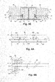
- the girder 1 is placed in situ and, on either side of the girder 1, the hollow-core slabs 30 have already been supported with their lower decks 32 on the support flanges 2a, 2b.
- the hollow-core slabs 30 have been prepared for the placement of coupling rods 20 (shown in dashed lines, as they are not present at that moment), and namely by, at the location of longitudinal voids 33, chopping the upper deck 31 away, so that longitudinal voids 33 close to the girder are accessible from the top for inserting the coupling rods 20.
- the opened longitudinal voids 33 have been sealed with plugs 34.
- the coupling plate 24 is then free to rotate under the influence of gravity, wherein the heavier arm 24b rotates downwards, until the edges 26a,b are stopped against the interior sides of the upper wall 9a and bottom wall 9b, respectively.
- the rod 21 will be rotated further into the hole 25 until the end face 23 of the rod 21 stops against the rear wall 8.
- the coupling plate 24 will be tensioned against the interior side of both flanges 10a and 10b.
- the coupling rod 21 now extends floating from the rail 6 in the elongated void 33.
- the accommodation spaces can be filled with concrete.
- the longitudinal voids 33 can easily be filled from the top, and the space between the girder 1 and the hollow-core slabs 30 and within the girder 1 can be filled via the gaps between the upper deck 31 of the hollow-core slabs 30 and the upper wall 4.
- the composite floor with integrated girder is nearly finished then. The tensile forces on the coupling rods 20 are transferred to the rail 6 and from the rail to the web 3 and/or via the dowels 15 to the concrete.
- cross-section of the rail can be adapted to the vertical orientation of the web, so that in case of an inclined web the opening of the rail can still have a horizontal normal.
Landscapes
- Engineering & Computer Science (AREA)
- Architecture (AREA)
- Physics & Mathematics (AREA)
- Electromagnetism (AREA)
- Civil Engineering (AREA)
- Structural Engineering (AREA)
- Bridges Or Land Bridges (AREA)
- Joining Of Building Structures In Genera (AREA)
Claims (15)
- Zusammenbau eines Stahlträgers (1) für einen Verbundboden mit Hohlkernbetonplatten (30) und eines Kupplungsgeräts (20) zum Verbinden der Hohlkernplatten mit dem Träger,
wobei der Träger umfasst:- zumindest einen seitlich verlaufenden, unteren Flansch (2) mit einer Stützfläche zum Stützen von Enden der Hohlkernplatten, und- einen Steg (3), der vom unteren Flansch nach oben verläuft,wobei das Kupplungsgerät umfasst:- eine Anzahl von Kupplungsstangen (21), die mit dem einen, ersten Ende in den jeweiligen Längshohlräumen (33) der Hohlkernplatten oder in Stoßstellen zwischen den Hohlkernplatten untergebracht und durch Gussbeton daran befestigt werden sollen, und die am anderen, zweiten Ende mit einem Kupplungsvorsprung (24) versehen sind, der querverlaufend von der jeweiligen Kupplungsstange vorsteht,- zumindest eine Kupplungsschiene (6a, 6b), die am Steg des Trägers angebracht ist, wobei die Schiene im Wesentlichen parallel zum unteren Flansch verläuft, und die eine Länge von zumindest der Breite einer Hohlkernplatte aufweist,wobei die Schiene einen Unterbringungsraum (12) für die Kupplungsvorsprünge (24) definiert, der zumindest teilweise zu den Hohlkernplatten hin in horizontaler Richtung durch eine Kupplungswand (10a, 10b) abgeschirmt ist und mit einer Öffnung (11) versehen ist, die in Längsrichtung für Zugang der Kupplungsvorsprünge zum Unterbringungsraum fortläuft, wobei die Öffnung eine Normale zum Unterbringungsraum hin aufweist, die im Wesentlichen horizontal ausgerichtet ist,
wobei die Kupplungsvorsprünge (24) in einer Einfügungsposition davon durch die Öffnung in den Unterbringungsraum eingeführt werden können und dann zu einer Kupplungsposition bewegt, insbesondere drehbar, werden können, die derart ausgerichtet ist, dass sie von der Einfügungsposition abweicht, um hinter der Kupplungswand (10a, 10b) in Eingriff zu treten. - Zusammenbau nach Anspruch 1, wobei die Schiene (6a, 6b) entlang einer Länge von mehreren Hohlkernplattenbreiten verläuft, wobei die Schiene vorzugsweise entlang zumindest nahezu der vollen Trägerlänge verläuft.
- Zusammenbau nach Anspruch 1 oder 2, wobei der Unterbringungsraum (12) aufwärts durch eine obere Wand (9a) begrenzt ist und abwärts durch eine untere Wand (9a) begrenzt ist.
- Zusammenbau nach einem der Ansprüche 1 bis 3, wobei die Kupplungswand einen hängenden Schienenflansch (10a) umfasst, der aufwärts die Öffnung (11) begrenzt, wobei der Kupplungsvorsprung (24) in der Kupplungsposition hinter dem hängenden Schienenflansch in Eingriff tritt, und/oder wobei die Kupplungswand einen aufrechten Schienenflansch (10b) umfasst, der abwärts die Öffnung (11) begrenzt, wobei der Kupplungsvorsprung (24) in der Kupplungsposition hinter dem aufrechten Schienenflansch in Eingriff tritt, wobei die Schiene (6a, 6b) vorzugsweise ein U-Profil ist, dessen beide Schenkel mit freien Kantenzonen zueinander hin gekehrt sind.
- Zusammenbau nach einem der Ansprüche 1 bis 4, wobei die Schiene (6a, 6b) in einem Abstand von ungefähr 1/5 bis 2/5 der Höhe des Stegs (3) über dem unteren Flansch (2) angeordnet ist.
- Zusammenbau nach einem der Ansprüche 1 bis 5, wobei, in einer ersten Richtung, quer zur Kupplungsstange verlaufend, der Kupplungsvorsprung (24) eine Abmessung aufweist, die kleiner als die Breite der Öffnung (11) ist, und in einer zweiten Richtung, quer zur Kupplungsstange verlaufend und in einem Winkel zur ersten Richtung, eine Abmessung aufweist, die größer als die Breite der Öffnung ist und vorzugsweise der inneren Höhe des Unterbringungsraums (12) entspricht.
- Zusammenbau nach einem der vorhergehenden Ansprüche, wobei der Kupplungsvorsprung (24) unter dem Einfluss der Schwerkraft zum Neigen zur Kupplungsposition geformt ist.
- Zusammenbau nach einem der Ansprüche 1 bis 7, wobei der Kupplungsvorsprung (24) ein Gewindeloch (25) aufweist und die Kupplungsstange (21) mit einem Gewindeende (22) versehen ist, das in das Loch eingeschraubt werden kann, wobei das Gewindeende der Kupplungsstange vorzugsweise durch das Loch geschraubt werden kann.
- Zusammenbau nach einem der Ansprüche 1 bis 8, wobei der Träger (1) zwei untere Flansche (2a, 2b) umfasst, die in entgegengesetzten Seitenrichtungen verlaufen, um eine Stützfläche für Hohlkernplatten (30) auf beiden Seiten des Stegs (3) auszubilden, wobei auf beiden Seiten des Stegs eine Schiene (6a, 6b) angeordnet ist, oder, wenn ein Doppelsteg (THQ-Träger) vorliegt, eine Schiene (6a, 6b) auf jedem Steg angeordnet ist, die voneinander abgewandt sind.
- Zusammenbau nach einem der Ansprüche 1 bis 9, wobei der Steg (3) wie eine gewellte oder zickzackförmige Wand gestaltet ist, mit ersten Wandsektionen (3a) auf der einen Seite, die in Trägerrichtung zueinander beabstandet sind, und zweiten Wandsektionen (3b) auf der gegenüberliegenden zweiten Seite, die in Trägerrichtung zueinander beabstandet sind, wobei der Steg vorzugsweise wie eine Wand mit einem trapezförmigem oder spundwandförmigem Verlauf gestaltet ist, wobei eine Schiene (6a, 6b) jedes Mal an den ersten Wandsektionen angebracht ist und/oder eine Schiene an den zweiten Wandsektionen angebracht ist, wobei vorzugsweise die ersten Wandsektionen in einer Ebene miteinander angeordnet sind und/oder die zweiten Wandsektionen in einer Ebene miteinander angeordnet sind.
- Zusammenbau nach Anspruch 10, wobei im Bereich zwischen zwei aufeinanderfolgenden ersten Wandsektionen (3a) ein oder mehr Dübel (15) an der Schiene (6a) angebracht sind, die an den ersten Wandsektionen angebracht ist, wobei die Dübel im Wesentlichen in horizontaler Richtung zu den zweiten Wandsektionen (3b) hin verlaufen, und/oder wobei im Bereich zwischen zwei aufeinanderfolgenden zweiten Wandsektionen (3b) ein oder mehr Dübel (15) an der Schiene (6b) angebracht sind, die an den zweiten Wandsektionen angebracht ist, wobei die Dübel im Wesentlichen in horizontaler Richtung zu den ersten Wandsektionen (3a) hin verlaufen.
- Bodenzusammenbau für einen Zusammenbau eines Stahlträgers nach Anspruch 1 bis 11, wobei der Bodenzusammenbau eine Anzahl von Hohlkernbetonplatten (30) und einen Träger (1) zum Stützen der Hohlkernplatten umfasst, wobei der Träger umfasst:- zumindest einen seitlich verlaufenden, unteren Flansch (2) mit einer Stützfläche zum Stützen von Enden der Hohlkernplatten, und- einen Steg (3), der vom unteren Flansch nach oben bis über die Hohlkernplatten verläuft,wobei die Hohlräume (33) der Hohlkernplatten, die in der Längsrichtung der Hohlkernplatten verlaufen, quer zum Träger verlaufen,
wobei der Raum zwischen den Stützenden der Hohlkernplatten und dem Steg des Trägers mit Gussbeton (41) gefüllt ist,
wobei ein Kupplungsgerät (20) zur Verbindung der Hohlkernplatten und des Trägers vorgesehen ist,
wobei das Kupplungsgerät umfasst:- eine Anzahl von Kupplungsstangen (21), die mit dem einen, ersten Ende in den jeweiligen Längshohlräumen der Hohlkernplatten oder in Stoßstellen zwischen den Hohlkernplatten untergebracht und durch Gussbeton (40)daran befestigt sind, und mit dem anderen, zweiten Ende am Träger mittels eines Kupplungsvorsprungs (24) befestigt sind, der querverlaufend von der jeweiligen Kupplungsstange vorsteht,- eine Kupplungsschiene (6a, 6b), die am Steg des Trägers angebracht ist, wobei die Schiene im Wesentlichen parallel zum unteren Flansch verläuft, und die eine Länge von zumindest der Breite einer Hohlkernplatte aufweist,wobei die Schiene einen Unterbringungsraum (12) für die Kupplungsvorsprünge (24) definiert, der zumindest teilweise zu den Hohlkernplatten hin in horizontaler Richtung durch eine Kupplungswand (10a, 10b) abgeschirmt ist und mit einer Öffnung (11) versehen ist, die in Längsrichtung für Zugang der Kupplungsvorsprünge zum Unterbringungsraum fortläuft,
wobei die Kupplungsvorsprünge im Unterbringungsraum der Schiene eingeschlossen sind. - Bodenzusammenbau nach Anspruch 12, wobei die Schiene (6a, 6b) auf einem Niveau angeordnet sind, das der Höhe der Längshohlräume (33) der Hohlkernplatten derart entspricht, dass die Kupplungsstange imstande ist, frei dort zu verlaufen.
- Verfahren zum Herstellen eines Verbundbodens, der aus Stahlträgern mit unteren Flanschen und Hohlkernbetonplatten gebildet ist, welche auf den unteren Flanschen dieser Träger gestützt sind, unter Benutzung eines Zusammenbaus nach einem der Ansprüche 1 bis 11, wobei an der Stelle der Längshohlräume, in denen die Kupplungsstangen positioniert werden sollen, das obere Deck der Hohlkernplatten entfernt wird, vor dem Anordnen der Hohlkernplatten oder im Anschluss daran,
wobei, nach dem Stützen der Hohlkernplatten auf dem jeweiligen unteren Flansch, die ersten Enden der Kupplungsstangen in die jeweiligen Längshohlräume eingefügt werden und an ihren zweiten Enden, mit den Kupplungsvorsprüngen in der Einfügungsposition, in einer horizontalen Richtung zur Schiene hin durch die Öffnung der Schiene in den Unterbringungsraum der Schiene eingefügt werden, wobei die Kupplungsvorsprünge zur Kupplungsposition hin bewegt, insbesondere gedreht, werden und die Kupplungsstangen in der korrekten Position in den Längshohlräumen gehalten werden, wonach der Raum um die Kupplungsstangen in den Längshohlräumen sowie der Raum zwischen dem Steg des Trägers und den Hohlkernplatten mit Beton gefüllt wird. - Verfahren nach Anspruch 14, wobei die Kupplungsvorsprünge zur Kupplungsposition hin gedreht werden, bis die Kupplungsvorsprünge Drehanschlag an den Schienenwänden erreichen, wobei die Kupplungsstangen vorzugsweise, sobald sie den Drehanschlag erreichen, weiter gedreht werden, um mit dem zweiten Ende weiter zum Steg hin bezüglich des Kupplungsvorsprungs bewegt zu werden, zum Anschlagen an einer Rückwand der Schiene oder am Steg, wonach aufgrund der Weiterdrehung der Kupplungsstange der Kupplungsvorsprung an der Kupplungswand gespannt wird.
Priority Applications (1)
| Application Number | Priority Date | Filing Date | Title |
|---|---|---|---|
| PL19162834T PL3540141T3 (pl) | 2018-03-14 | 2019-03-14 | Zespół belek do stropu kompozytowego |
Applications Claiming Priority (1)
| Application Number | Priority Date | Filing Date | Title |
|---|---|---|---|
| NL2020588A NL2020588B1 (nl) | 2018-03-14 | 2018-03-14 | Liggersamenstel voor composietvloer |
Publications (2)
| Publication Number | Publication Date |
|---|---|
| EP3540141A1 EP3540141A1 (de) | 2019-09-18 |
| EP3540141B1 true EP3540141B1 (de) | 2021-04-07 |
Family
ID=61800639
Family Applications (1)
| Application Number | Title | Priority Date | Filing Date |
|---|---|---|---|
| EP19162834.6A Active EP3540141B1 (de) | 2018-03-14 | 2019-03-14 | Trägeranordnung für verbundboden |
Country Status (5)
| Country | Link |
|---|---|
| EP (1) | EP3540141B1 (de) |
| DK (1) | DK3540141T3 (de) |
| ES (1) | ES2878748T3 (de) |
| NL (1) | NL2020588B1 (de) |
| PL (1) | PL3540141T3 (de) |
Families Citing this family (2)
| Publication number | Priority date | Publication date | Assignee | Title |
|---|---|---|---|---|
| CN113378255B (zh) * | 2020-02-25 | 2024-08-06 | 比亚迪股份有限公司 | 一种曲线导轨梁的设计方法和曲线导轨梁 |
| CN114457915B (zh) * | 2022-02-23 | 2023-10-27 | 中国建筑一局(集团)有限公司 | 一种用于超高层复杂钢结构的快速安装节点构造及钢结构安装方法 |
Family Cites Families (4)
| Publication number | Priority date | Publication date | Assignee | Title |
|---|---|---|---|---|
| KR101012010B1 (ko) * | 2008-06-30 | 2011-01-31 | 서울시립대학교 산학협력단 | 골형 웨브 강판 조립보 |
| DE102010025042A1 (de) * | 2010-06-22 | 2011-12-22 | Deltastaal B.V. | Stahlträger für Fertigteildecken |
| CN105019595A (zh) * | 2015-07-30 | 2015-11-04 | 东南大学 | 一种钢-混凝土组合结构波折形钢腹板 |
| DE202015104628U1 (de) * | 2015-09-01 | 2016-12-05 | Pfeifer Holding Gmbh & Co. Kg | Tragbalken für Deckensysteme und Deckensystem |
-
2018
- 2018-03-14 NL NL2020588A patent/NL2020588B1/nl active
-
2019
- 2019-03-14 PL PL19162834T patent/PL3540141T3/pl unknown
- 2019-03-14 ES ES19162834T patent/ES2878748T3/es active Active
- 2019-03-14 EP EP19162834.6A patent/EP3540141B1/de active Active
- 2019-03-14 DK DK19162834.6T patent/DK3540141T3/da active
Non-Patent Citations (1)
| Title |
|---|
| None * |
Also Published As
| Publication number | Publication date |
|---|---|
| DK3540141T3 (da) | 2022-08-08 |
| PL3540141T3 (pl) | 2021-10-25 |
| NL2020588B1 (nl) | 2019-09-26 |
| EP3540141A1 (de) | 2019-09-18 |
| ES2878748T3 (es) | 2021-11-19 |
Similar Documents
| Publication | Publication Date | Title |
|---|---|---|
| CA2017669C (en) | Curtain wall for a building | |
| US12276099B2 (en) | Modular building systems | |
| US8800725B2 (en) | Elevator liner apparatus and utilization method thereof | |
| KR101614842B1 (ko) | 층고 증가 없이 다양한 스팬에 적용가능한 내민보 일체형 pc기둥을 이용한 건축물의 골조시스템 | |
| EP3540141B1 (de) | Trägeranordnung für verbundboden | |
| KR101658648B1 (ko) | 보 관통형 기둥접합부 및 이를 이용한 건축물 상하부 병행 구축 공법 | |
| KR20200112052A (ko) | 타설압 저항성이 강화된 프리캐스트 벽체 | |
| US20240328154A1 (en) | Primary Shell Structure Consisting of Plane Load-bearing Modules Made of Elements and Assembly Methods | |
| JP2018059311A (ja) | 床版取替工法 | |
| CN109184199B (zh) | 3m预应力拱板现浇施工时圈梁抗扭抗剪加固方法 | |
| JP4977110B2 (ja) | 合成桁の構造及び合成桁の構築方法 | |
| EP0016478A2 (de) | Wand aus einer Mehrzahl von vorgefertigten Zementplatten | |
| JP2754369B2 (ja) | 建築構造物のボイドスラブ用鉄筋ユニット | |
| CN212336674U (zh) | 一种高层高空大跨度悬空结构施工承力平台 | |
| JP7322354B2 (ja) | トラックバース構造 | |
| AU2017377663A1 (en) | Support module for a structure | |
| WO2017217863A1 (en) | A building structure connecting means and a method of using same | |
| CN100374668C (zh) | 柱悬挂桁架系统 | |
| JP3251365U (ja) | 簡易的に連結および引っ越しが可能なコンテナハウス | |
| US20070079570A1 (en) | Reinforced Concrete Forming System | |
| RU2854131C1 (ru) | Закладное изделие | |
| EP3469160B1 (de) | Gebäudestrukturverbindung und verfahren zur verwendung davon | |
| CN223433947U (zh) | 一种钢梁与钢筋混凝土柱连接的梁柱连接节点 | |
| JP7492073B1 (ja) | 設備架台の施工方法 | |
| AU2021204208B2 (en) | Modified widened container |
Legal Events
| Date | Code | Title | Description |
|---|---|---|---|
| PUAI | Public reference made under article 153(3) epc to a published international application that has entered the european phase |
Free format text: ORIGINAL CODE: 0009012 |
|
| STAA | Information on the status of an ep patent application or granted ep patent |
Free format text: STATUS: THE APPLICATION HAS BEEN PUBLISHED |
|
| AK | Designated contracting states |
Kind code of ref document: A1 Designated state(s): AL AT BE BG CH CY CZ DE DK EE ES FI FR GB GR HR HU IE IS IT LI LT LU LV MC MK MT NL NO PL PT RO RS SE SI SK SM TR |
|
| AX | Request for extension of the european patent |
Extension state: BA ME |
|
| STAA | Information on the status of an ep patent application or granted ep patent |
Free format text: STATUS: REQUEST FOR EXAMINATION WAS MADE |
|
| 17P | Request for examination filed |
Effective date: 20191121 |
|
| RBV | Designated contracting states (corrected) |
Designated state(s): AL AT BE BG CH CY CZ DE DK EE ES FI FR GB GR HR HU IE IS IT LI LT LU LV MC MK MT NL NO PL PT RO RS SE SI SK SM TR |
|
| GRAP | Despatch of communication of intention to grant a patent |
Free format text: ORIGINAL CODE: EPIDOSNIGR1 |
|
| STAA | Information on the status of an ep patent application or granted ep patent |
Free format text: STATUS: GRANT OF PATENT IS INTENDED |
|
| RIC1 | Information provided on ipc code assigned before grant |
Ipc: E04C 3/293 20060101ALN20200416BHEP Ipc: E04B 5/29 20060101AFI20200416BHEP |
|
| RIC1 | Information provided on ipc code assigned before grant |
Ipc: E04B 5/29 20060101AFI20200422BHEP Ipc: E04C 3/293 20060101ALN20200422BHEP |
|
| INTG | Intention to grant announced |
Effective date: 20200508 |
|
| GRAJ | Information related to disapproval of communication of intention to grant by the applicant or resumption of examination proceedings by the epo deleted |
Free format text: ORIGINAL CODE: EPIDOSDIGR1 |
|
| STAA | Information on the status of an ep patent application or granted ep patent |
Free format text: STATUS: REQUEST FOR EXAMINATION WAS MADE |
|
| INTC | Intention to grant announced (deleted) | ||
| GRAP | Despatch of communication of intention to grant a patent |
Free format text: ORIGINAL CODE: EPIDOSNIGR1 |
|
| RIC1 | Information provided on ipc code assigned before grant |
Ipc: E04B 5/29 20060101AFI20201006BHEP Ipc: E04C 3/293 20060101ALN20201006BHEP |
|
| STAA | Information on the status of an ep patent application or granted ep patent |
Free format text: STATUS: GRANT OF PATENT IS INTENDED |
|
| INTG | Intention to grant announced |
Effective date: 20201112 |
|
| GRAS | Grant fee paid |
Free format text: ORIGINAL CODE: EPIDOSNIGR3 |
|
| GRAA | (expected) grant |
Free format text: ORIGINAL CODE: 0009210 |
|
| STAA | Information on the status of an ep patent application or granted ep patent |
Free format text: STATUS: THE PATENT HAS BEEN GRANTED |
|
| AK | Designated contracting states |
Kind code of ref document: B1 Designated state(s): AL AT BE BG CH CY CZ DE DK EE ES FI FR GB GR HR HU IE IS IT LI LT LU LV MC MK MT NL NO PL PT RO RS SE SI SK SM TR |
|
| REG | Reference to a national code |
Ref country code: GB Ref legal event code: FG4D |
|
| REG | Reference to a national code |
Ref country code: CH Ref legal event code: EP Ref country code: AT Ref legal event code: REF Ref document number: 1379866 Country of ref document: AT Kind code of ref document: T Effective date: 20210415 |
|
| REG | Reference to a national code |
Ref country code: DE Ref legal event code: R096 Ref document number: 602019003679 Country of ref document: DE |
|
| REG | Reference to a national code |
Ref country code: IE Ref legal event code: FG4D |
|
| REG | Reference to a national code |
Ref country code: FI Ref legal event code: FGE Ref country code: NL Ref legal event code: FP |
|
| REG | Reference to a national code |
Ref country code: LT Ref legal event code: MG9D |
|
| REG | Reference to a national code |
Ref country code: SE Ref legal event code: TRGR |
|
| REG | Reference to a national code |
Ref country code: SK Ref legal event code: T3 Ref document number: E 37539 Country of ref document: SK |
|
| REG | Reference to a national code |
Ref country code: NO Ref legal event code: T2 Effective date: 20210407 |
|
| PG25 | Lapsed in a contracting state [announced via postgrant information from national office to epo] |
Ref country code: BG Free format text: LAPSE BECAUSE OF FAILURE TO SUBMIT A TRANSLATION OF THE DESCRIPTION OR TO PAY THE FEE WITHIN THE PRESCRIBED TIME-LIMIT Effective date: 20210707 Ref country code: HR Free format text: LAPSE BECAUSE OF FAILURE TO SUBMIT A TRANSLATION OF THE DESCRIPTION OR TO PAY THE FEE WITHIN THE PRESCRIBED TIME-LIMIT Effective date: 20210407 Ref country code: LT Free format text: LAPSE BECAUSE OF FAILURE TO SUBMIT A TRANSLATION OF THE DESCRIPTION OR TO PAY THE FEE WITHIN THE PRESCRIBED TIME-LIMIT Effective date: 20210407 |
|
| REG | Reference to a national code |
Ref country code: ES Ref legal event code: FG2A Ref document number: 2878748 Country of ref document: ES Kind code of ref document: T3 Effective date: 20211119 |
|
| PG25 | Lapsed in a contracting state [announced via postgrant information from national office to epo] |
Ref country code: GR Free format text: LAPSE BECAUSE OF FAILURE TO SUBMIT A TRANSLATION OF THE DESCRIPTION OR TO PAY THE FEE WITHIN THE PRESCRIBED TIME-LIMIT Effective date: 20210708 Ref country code: IS Free format text: LAPSE BECAUSE OF FAILURE TO SUBMIT A TRANSLATION OF THE DESCRIPTION OR TO PAY THE FEE WITHIN THE PRESCRIBED TIME-LIMIT Effective date: 20210807 Ref country code: LV Free format text: LAPSE BECAUSE OF FAILURE TO SUBMIT A TRANSLATION OF THE DESCRIPTION OR TO PAY THE FEE WITHIN THE PRESCRIBED TIME-LIMIT Effective date: 20210407 Ref country code: RS Free format text: LAPSE BECAUSE OF FAILURE TO SUBMIT A TRANSLATION OF THE DESCRIPTION OR TO PAY THE FEE WITHIN THE PRESCRIBED TIME-LIMIT Effective date: 20210407 Ref country code: PT Free format text: LAPSE BECAUSE OF FAILURE TO SUBMIT A TRANSLATION OF THE DESCRIPTION OR TO PAY THE FEE WITHIN THE PRESCRIBED TIME-LIMIT Effective date: 20210809 |
|
| REG | Reference to a national code |
Ref country code: DE Ref legal event code: R097 Ref document number: 602019003679 Country of ref document: DE |
|
| PG25 | Lapsed in a contracting state [announced via postgrant information from national office to epo] |
Ref country code: EE Free format text: LAPSE BECAUSE OF FAILURE TO SUBMIT A TRANSLATION OF THE DESCRIPTION OR TO PAY THE FEE WITHIN THE PRESCRIBED TIME-LIMIT Effective date: 20210407 Ref country code: SM Free format text: LAPSE BECAUSE OF FAILURE TO SUBMIT A TRANSLATION OF THE DESCRIPTION OR TO PAY THE FEE WITHIN THE PRESCRIBED TIME-LIMIT Effective date: 20210407 Ref country code: RO Free format text: LAPSE BECAUSE OF FAILURE TO SUBMIT A TRANSLATION OF THE DESCRIPTION OR TO PAY THE FEE WITHIN THE PRESCRIBED TIME-LIMIT Effective date: 20210407 |
|
| PLBE | No opposition filed within time limit |
Free format text: ORIGINAL CODE: 0009261 |
|
| STAA | Information on the status of an ep patent application or granted ep patent |
Free format text: STATUS: NO OPPOSITION FILED WITHIN TIME LIMIT |
|
| 26N | No opposition filed |
Effective date: 20220110 |
|
| PG25 | Lapsed in a contracting state [announced via postgrant information from national office to epo] |
Ref country code: IS Free format text: LAPSE BECAUSE OF FAILURE TO SUBMIT A TRANSLATION OF THE DESCRIPTION OR TO PAY THE FEE WITHIN THE PRESCRIBED TIME-LIMIT Effective date: 20210807 Ref country code: AL Free format text: LAPSE BECAUSE OF FAILURE TO SUBMIT A TRANSLATION OF THE DESCRIPTION OR TO PAY THE FEE WITHIN THE PRESCRIBED TIME-LIMIT Effective date: 20210407 |
|
| REG | Reference to a national code |
Ref country code: DK Ref legal event code: T3 Effective date: 20220802 Ref country code: DK Ref legal event code: EGE Effective date: 20220802 |
|
| REG | Reference to a national code |
Ref country code: AT Ref legal event code: UEP Ref document number: 1379866 Country of ref document: AT Kind code of ref document: T Effective date: 20210407 |
|
| PG25 | Lapsed in a contracting state [announced via postgrant information from national office to epo] |
Ref country code: MC Free format text: LAPSE BECAUSE OF FAILURE TO SUBMIT A TRANSLATION OF THE DESCRIPTION OR TO PAY THE FEE WITHIN THE PRESCRIBED TIME-LIMIT Effective date: 20210407 |
|
| PG25 | Lapsed in a contracting state [announced via postgrant information from national office to epo] |
Ref country code: MK Free format text: LAPSE BECAUSE OF FAILURE TO SUBMIT A TRANSLATION OF THE DESCRIPTION OR TO PAY THE FEE WITHIN THE PRESCRIBED TIME-LIMIT Effective date: 20210407 Ref country code: CY Free format text: LAPSE BECAUSE OF FAILURE TO SUBMIT A TRANSLATION OF THE DESCRIPTION OR TO PAY THE FEE WITHIN THE PRESCRIBED TIME-LIMIT Effective date: 20210407 |
|
| PG25 | Lapsed in a contracting state [announced via postgrant information from national office to epo] |
Ref country code: HU Free format text: LAPSE BECAUSE OF FAILURE TO SUBMIT A TRANSLATION OF THE DESCRIPTION OR TO PAY THE FEE WITHIN THE PRESCRIBED TIME-LIMIT; INVALID AB INITIO Effective date: 20190314 |
|
| PG25 | Lapsed in a contracting state [announced via postgrant information from national office to epo] |
Ref country code: MT Free format text: LAPSE BECAUSE OF FAILURE TO SUBMIT A TRANSLATION OF THE DESCRIPTION OR TO PAY THE FEE WITHIN THE PRESCRIBED TIME-LIMIT Effective date: 20210407 |
|
| PGFP | Annual fee paid to national office [announced via postgrant information from national office to epo] |
Ref country code: ES Payment date: 20250401 Year of fee payment: 7 |
|
| PGFP | Annual fee paid to national office [announced via postgrant information from national office to epo] |
Ref country code: CH Payment date: 20250401 Year of fee payment: 7 |
|
| PG25 | Lapsed in a contracting state [announced via postgrant information from national office to epo] |
Ref country code: TR Free format text: LAPSE BECAUSE OF FAILURE TO SUBMIT A TRANSLATION OF THE DESCRIPTION OR TO PAY THE FEE WITHIN THE PRESCRIBED TIME-LIMIT Effective date: 20210407 |
|
| REG | Reference to a national code |
Ref country code: CH Ref legal event code: U11 Free format text: ST27 STATUS EVENT CODE: U-0-0-U10-U11 (AS PROVIDED BY THE NATIONAL OFFICE) Effective date: 20260401 |
|
| PGFP | Annual fee paid to national office [announced via postgrant information from national office to epo] |
Ref country code: SE Payment date: 20260319 Year of fee payment: 8 |
|
| PGFP | Annual fee paid to national office [announced via postgrant information from national office to epo] |
Ref country code: GB Payment date: 20260324 Year of fee payment: 8 |
|
| PGFP | Annual fee paid to national office [announced via postgrant information from national office to epo] |
Ref country code: DE Payment date: 20260319 Year of fee payment: 8 Ref country code: NO Payment date: 20260323 Year of fee payment: 8 Ref country code: DK Payment date: 20260324 Year of fee payment: 8 Ref country code: IE Payment date: 20260319 Year of fee payment: 8 |
|
| PGFP | Annual fee paid to national office [announced via postgrant information from national office to epo] |
Ref country code: AT Payment date: 20260320 Year of fee payment: 8 |
|
| PGFP | Annual fee paid to national office [announced via postgrant information from national office to epo] |
Ref country code: LU Payment date: 20260319 Year of fee payment: 8 Ref country code: FI Payment date: 20260323 Year of fee payment: 8 Ref country code: BE Payment date: 20260319 Year of fee payment: 8 Ref country code: IT Payment date: 20260324 Year of fee payment: 8 |
|
| PGFP | Annual fee paid to national office [announced via postgrant information from national office to epo] |
Ref country code: NL Payment date: 20260319 Year of fee payment: 8 |
|
| PGFP | Annual fee paid to national office [announced via postgrant information from national office to epo] |
Ref country code: FR Payment date: 20260320 Year of fee payment: 8 |
|
| PGFP | Annual fee paid to national office [announced via postgrant information from national office to epo] |
Ref country code: CZ Payment date: 20260310 Year of fee payment: 8 |
|
| PGFP | Annual fee paid to national office [announced via postgrant information from national office to epo] |
Ref country code: PL Payment date: 20260306 Year of fee payment: 8 |
|
| PGFP | Annual fee paid to national office [announced via postgrant information from national office to epo] |
Ref country code: SK Payment date: 20260310 Year of fee payment: 8 |