EP3539680B1 - Piezoelektrischer aktuator und piezoelektrisches ventil - Google Patents
Piezoelektrischer aktuator und piezoelektrisches ventil Download PDFInfo
- Publication number
- EP3539680B1 EP3539680B1 EP17869630.8A EP17869630A EP3539680B1 EP 3539680 B1 EP3539680 B1 EP 3539680B1 EP 17869630 A EP17869630 A EP 17869630A EP 3539680 B1 EP3539680 B1 EP 3539680B1
- Authority
- EP
- European Patent Office
- Prior art keywords
- piezoelectric
- piezoelectric element
- processing unit
- displacement
- valve
- Prior art date
- Legal status (The legal status is an assumption and is not a legal conclusion. Google has not performed a legal analysis and makes no representation as to the accuracy of the status listed.)
- Active
Links
Images


Classifications
-
- F—MECHANICAL ENGINEERING; LIGHTING; HEATING; WEAPONS; BLASTING
- F16—ENGINEERING ELEMENTS AND UNITS; GENERAL MEASURES FOR PRODUCING AND MAINTAINING EFFECTIVE FUNCTIONING OF MACHINES OR INSTALLATIONS; THERMAL INSULATION IN GENERAL
- F16K—VALVES; TAPS; COCKS; ACTUATING-FLOATS; DEVICES FOR VENTING OR AERATING
- F16K31/00—Actuating devices; Operating means; Releasing devices
-
- B—PERFORMING OPERATIONS; TRANSPORTING
- B06—GENERATING OR TRANSMITTING MECHANICAL VIBRATIONS IN GENERAL
- B06B—METHODS OR APPARATUS FOR GENERATING OR TRANSMITTING MECHANICAL VIBRATIONS OF INFRASONIC, SONIC, OR ULTRASONIC FREQUENCY, e.g. FOR PERFORMING MECHANICAL WORK IN GENERAL
- B06B1/00—Methods or apparatus for generating mechanical vibrations of infrasonic, sonic, or ultrasonic frequency
- B06B1/02—Methods or apparatus for generating mechanical vibrations of infrasonic, sonic, or ultrasonic frequency making use of electrical energy
- B06B1/06—Methods or apparatus for generating mechanical vibrations of infrasonic, sonic, or ultrasonic frequency making use of electrical energy operating with piezoelectric effect or with electrostriction
-
- H—ELECTRICITY
- H02—GENERATION; CONVERSION OR DISTRIBUTION OF ELECTRIC POWER
- H02N—ELECTRIC MACHINES NOT OTHERWISE PROVIDED FOR
- H02N2/00—Electric machines in general using piezoelectric effect, electrostriction or magnetostriction
- H02N2/02—Electric machines in general using piezoelectric effect, electrostriction or magnetostriction producing linear motion, e.g. actuators; Linear positioners ; Linear motors
- H02N2/06—Drive circuits; Control arrangements or methods
-
- F—MECHANICAL ENGINEERING; LIGHTING; HEATING; WEAPONS; BLASTING
- F01—MACHINES OR ENGINES IN GENERAL; ENGINE PLANTS IN GENERAL; STEAM ENGINES
- F01L—CYCLICALLY OPERATING VALVES FOR MACHINES OR ENGINES
- F01L9/00—Valve-gear or valve arrangements actuated non-mechanically
- F01L9/20—Valve-gear or valve arrangements actuated non-mechanically by electric means
-
- F—MECHANICAL ENGINEERING; LIGHTING; HEATING; WEAPONS; BLASTING
- F16—ENGINEERING ELEMENTS AND UNITS; GENERAL MEASURES FOR PRODUCING AND MAINTAINING EFFECTIVE FUNCTIONING OF MACHINES OR INSTALLATIONS; THERMAL INSULATION IN GENERAL
- F16K—VALVES; TAPS; COCKS; ACTUATING-FLOATS; DEVICES FOR VENTING OR AERATING
- F16K31/00—Actuating devices; Operating means; Releasing devices
- F16K31/004—Actuating devices; Operating means; Releasing devices actuated by piezoelectric means
-
- F—MECHANICAL ENGINEERING; LIGHTING; HEATING; WEAPONS; BLASTING
- F16—ENGINEERING ELEMENTS AND UNITS; GENERAL MEASURES FOR PRODUCING AND MAINTAINING EFFECTIVE FUNCTIONING OF MACHINES OR INSTALLATIONS; THERMAL INSULATION IN GENERAL
- F16K—VALVES; TAPS; COCKS; ACTUATING-FLOATS; DEVICES FOR VENTING OR AERATING
- F16K31/00—Actuating devices; Operating means; Releasing devices
- F16K31/02—Actuating devices; Operating means; Releasing devices electric; magnetic
-
- H—ELECTRICITY
- H02—GENERATION; CONVERSION OR DISTRIBUTION OF ELECTRIC POWER
- H02N—ELECTRIC MACHINES NOT OTHERWISE PROVIDED FOR
- H02N2/00—Electric machines in general using piezoelectric effect, electrostriction or magnetostriction
- H02N2/02—Electric machines in general using piezoelectric effect, electrostriction or magnetostriction producing linear motion, e.g. actuators; Linear positioners ; Linear motors
- H02N2/04—Constructional details
- H02N2/043—Mechanical transmission means, e.g. for stroke amplification
-
- H—ELECTRICITY
- H02—GENERATION; CONVERSION OR DISTRIBUTION OF ELECTRIC POWER
- H02N—ELECTRIC MACHINES NOT OTHERWISE PROVIDED FOR
- H02N2/00—Electric machines in general using piezoelectric effect, electrostriction or magnetostriction
- H02N2/10—Electric machines in general using piezoelectric effect, electrostriction or magnetostriction producing rotary motion, e.g. rotary motors
- H02N2/14—Drive circuits; Control arrangements or methods
-
- F—MECHANICAL ENGINEERING; LIGHTING; HEATING; WEAPONS; BLASTING
- F01—MACHINES OR ENGINES IN GENERAL; ENGINE PLANTS IN GENERAL; STEAM ENGINES
- F01L—CYCLICALLY OPERATING VALVES FOR MACHINES OR ENGINES
- F01L9/00—Valve-gear or valve arrangements actuated non-mechanically
- F01L9/20—Valve-gear or valve arrangements actuated non-mechanically by electric means
- F01L9/24—Piezoelectric actuators
Definitions
- the present invention relates to a piezoelectric actuator and a piezoelectric valve which drive an object by enlarging a displacement of a piezoelectric element (piezo element).
- the piezoelectric valve shown in FIG. 1 of Patent Document 1 incorporates a piezoelectric actuator. Expansion and contraction operations of the piezoelectric actuator open and close a valve portion at a tip of the actuator.
- a normal pulse drive voltage shown in FIG. 2(a) of the same document is applied to a piezoelectric actuator.
- this pressure fluctuation is suppressed by applying a voltage in a multistage manner as shown in FIG. 3 and FIG. 4 of the same document.
- Patent Document 2 illustrates an example in which vibration is suppressed by inserting a prepulse such as that shown in FIG. 4B, FIG. 5A or the like of the same document.
- document JP 2011 143099 A refers to a vibration element driving circuit that includes a first filter part outputting a signal component of a relatively low first frequency range of an input signal, a second filter part outputting a signal component of a second frequency range higher than the first frequency range of the input signal, an addition part for adding an output signal from the first filter part and an output signal from the second filter part, and a driving part for generating a driving signal by power-amplifying an output signal from the addition circuit.
- a vibration element driving circuit that includes a first filter part outputting a signal component of a relatively low first frequency range of an input signal, a second filter part outputting a signal component of a second frequency range higher than the first frequency range of the input signal, an addition part for adding an output signal from the first filter part and an output signal from the second filter part, and a driving part for generating a driving signal by power-amplifying an output signal from the addition circuit.
- Patent Document 1 a piezoelectric air valve moves a valve body through a displacement enlarging mechanism, and therefore the invention is carefully devised to apply a voltage under a recognition that the valve body vibrates and an air jet amount from a nozzle fluctuates when an air jet duration time becomes long and stable operation cannot be obtained.
- a pressure fluctuation is due to a mechanical resonance of the piezoelectric actuator, and vibration due to resonance occurs during expansion and contraction of the piezoelectric actuator, and this is mainly due to changes in an opening of a valve portion.
- Patent Document 1 has the following problems to be solved.
- the present invention has been made in view of such problems, and it is an object of the present invention to provide unconventional piezoelectric valve actuator and piezoelectric valve which can be applied to a piezoelectric valve or the like to cause an operating body such as a valve body to perform an appropriate operation.
- the present invention has implemented the following means in order to achieve such an object.
- the piezoelectric actuator of the present invention includes: a piezoelectric element which generates, as a displacement, a driving force necessary for an operation of an operating body; a displacement enlarging mechanism including at least a spring element so as to enlarge a displacement of the aforementioned piezoelectric element which acts on the aforementioned operating body; and a driving means which operates the aforementioned operating body through the displacement enlarging mechanism by applying a voltage to the aforementioned piezoelectric element based on a voltage command of a pulse waveform to extend the piezoelectric element, wherein the aforementioned spring element constitutes a spring elasticity of an actuator body constituting the piezoelectric actuator, the aforementioned driving means includes a notch filter as a resonance suppression processing unit having an inverse function characteristic of a mechanical resonance frequency by the spring elasticity when operating the aforementioned displacement enlarging mechanism, and is configured to apply, a voltage based on the voltage command of a pulse waveform in which the mechanical resonance of the displacement
- the resonance suppression processing unit with the inverse function characteristic is properly configured.
- the aforementioned driving means includes a delay compensation processing unit having an inverse characteristic of an electrical driving characteristic causing a delay when driving the aforementioned piezoelectric element, and is configured to apply, a voltage which reduces an influence of the aforementioned electrical driving characteristic, to the aforementioned piezoelectric element through this delay compensation processing unit.
- a specific embodiment may include a driving means in which the delay compensation processing unit is a high pass filter.
- a piezoelectric valve is configured, using such piezoelectric actuator, to include: a valve main body in which a gas pressure chamber receiving compressed gas supplied from an outside and a gas exhaust passage exhausting the aforementioned compressed gas from the gas pressure chamber are formed; and a valve body which is an operating body disposed in the aforementioned gas pressure chamber and opening and closing the aforementioned gas exhaust passage, it is possible to cause the piezoelectric valve to perform stable and reliable opening and closing operations at a high speed.
- FIG. 1 is a V diagram showing a piezoelectric valve V of this embodiment, and the piezoelectric valve V includes: a valve main body 11 in which a gas pressure chamber 111 receiving compressed gas supplied from an outside and a gas exhaust passage 112 exhausting the compressed gas from the gas pressure chamber 111 are formed; and a valve body 12 which is disposed in the aforementioned gas pressure chamber 111 and opening and closing the gas exhaust passage 112. Then, a piezoelectric actuator A having this valve body 12 as an operating body is configured to be integrally incorporated in the valve main body 11.
- the piezoelectric actuator A includes, as a basic configuration: a piezoelectric element 13 which generates, as a displacement, a driving force necessary for an operation of a valve body 12 which is an operating body; a displacement enlarging mechanism 14 including at least a spring element so as to enlarge the displacement of this piezoelectric element 13 which acts on the aforementioned valve body 12; and a driving means 15 which operates the valve body 12 that is the aforementioned operating body by applying a voltage to the aforementioned piezoelectric element 13 to extend the piezoelectric element 13.
- the aforementioned valve body 12 is disposed in the gas pressure chamber 111 of the valve main body 11 at a position for opening and closing the gas exhaust passage 112.
- the aforementioned piezoelectric element 13 is disposed inside a U-shaped base substrate 10 of the aforementioned valve main body 11, that will be described later.
- the aforementioned displacement enlarging mechanism 14 is disposed in the aforementioned gas pressure chamber 111 of the aforementioned valve main body 11, and enlarges the displacement of the aforementioned piezoelectric element 13 which acts on the aforementioned valve body 12.
- the aforementioned driving device 15 includes: a charging drive circuit (not shown) which applies a drive voltage to the aforementioned piezoelectric element 13 to charge an electric charge, thereby extending the piezoelectric element 13; and a discharging drive circuit (not shown) which discharges the aforementioned charged electric charge and contracts the aforementioned piezoelectric element 13, and extends and contracts the aforementioned piezoelectric element 13, thereby driving the aforementioned valve body 12 to open and close.
- the aforementioned displacement enlarging mechanism 14 includes: a displacement enlarging section 14a which enlarges the displacement of the aforementioned piezoelectric element 13; and a displacement transmitting section 14b which transmits the displacement of the aforementioned piezoelectric element 13 to the aforementioned displacement enlarging section 14a.
- the aforementioned displacement transmitting section 14b includes the U-shaped base substrate 10 to which a one end of the aforementioned piezoelectric element 13 is joined and a cap member 18a to which another end of the aforementioned piezoelectric element 13 is joined.
- the aforementioned piezoelectric element 13 is incorporated in a space of the aforementioned U-shaped base substrate 10 between a U-shaped bottom section and the aforementioned cap member 18a, and the aforementioned one end is joined to the aforementioned base substrate 10, and the aforementioned other end is joined to the aforementioned cap member 18a.
- the displacement transmitting section 14b and the displacement enlarging section 14a are configured to include a first hinge 16, a second hinge 17, a first arm member 18 and a leaf spring 19.
- a one end of the first hinge 16 is joined to the base substrate 10.
- a one end of the second hinge 17 is joined to the cap member 18a attached to the aforementioned piezoelectric element 13. Both other ends of the first hinge 16 and the second hinge 17 are joined to a base of the arm member 18.
- a one end of the leaf spring 19 is joined to an outer leading end part of the arm member 18, and an inner end of the leaf spring 19 is joined to a nearest end of the valve body 12.
- the piezoelectric element 13 in a state of FIG. 1 , when a drive voltage is applied to the piezoelectric element 13 by the driving means 15 to charge the electric charge, the piezoelectric element 13 extends in a left direction in the figure.
- the displacement caused by the extension of the piezoelectric element 13 is enlarged by a principle of leverage in the displacement enlarging mechanism 14 with the second hinge 17 as a force point, the first hinge 16 as a supporting point, and the leading end part of the arm member 18 as an action point, and the outer leading end part of the arm member 18 is largely displaced in a direction in which a distance between a pair of the arm members 18, 18 extends.
- the piezoelectric element 13 when the abovementioned piezoelectric element 13 discharges electric charge by the driving device 15, the piezoelectric element 13 contracts and the contraction is transmitted to the valve body 12 through the displacement enlarging mechanism 14, and the valve body 12 sits on the valve seat 113.
- the spring element of the displacement enlarging mechanism 14 resonates in a same mode as a series of operation modes of the aforementioned displacement enlarging mechanism.
- the resonance frequency of the pair of leaf springs 19, 19 is also influenced by a structure, it is generally considered that the resonance frequency is very high and resonance vibration is small.
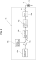
- the driving means (controller) 15 shown in FIG. 2 originally inputs to a drive circuit 15d, a drive pulse obtained by multiplying, an output signal waveform (pulse waveform) generated by an output signal generator 15a by a voltage level value set by an output voltage setting unit 15b, by a multiplication unit 15c, to generate a drive voltage for the piezoelectric element 13.
- the present embodiment incorporates: a first filter processing unit 15x as a resonance suppression processing unit having an inverse function characteristic of a mechanical resonance frequency when operating the aforementioned displacement enlarging mechanism 14; and a second filter processing unit 15y as a delay compensation processing unit having an inverse characteristic of an electrical driving characteristic causing a delay when driving the aforementioned piezoelectric element 13, and is configured to apply, a voltage in which an influence of the aforementioned mechanical resonance is reduced, to the aforementioned piezoelectric element 13 through the first filter processing unit 15x, and to apply, a voltage in which an influence of the aforementioned electrical driving characteristic is reduced, to the aforementioned piezoelectric element 13 through the second filter processing unit 15y.
- the first filter processing unit 15x is configured by a notch filter.
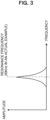
- the mechanical resonance frequency characteristic of an actuator main body a1 (see FIG. 1 ) constituting the piezoelectric actuator A can be determined from an analysis or the like, and from an excitation form, only a vibration mode as shown by an arrow in FIG. 1 appears. Therefore, a resonance frequency of f0KHz as shown in FIG. 3 can be determined.
- the first filter processing unit 15x in order to remove this frequency component from a square wave coming out of a multiplier 15c, the first filter processing unit 15x, as shown in FIG.
- this first filter processing unit 15x is not a low pass filter is that the low pass filter does not have a frequency component higher than the mechanical resonance of the actuator main body a1, and thus a response delay occurs. If the response delay is acceptable, the low pass filter may be adopted as the first filter processing unit 15x.
- the signal waveform from the notch filter used in the first filter processing unit 15x is input to the second filter processing unit 15y.
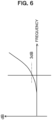
- the piezoelectric element 13 moves by voltage, and thus lags the current. Focusing on an electrical characteristic, in this embodiment, a low-pass filter with a cutoff frequency of fcKHz at -3 dB is formed as shown in FIG. 5 , on the basis of an output impedance R of a control means 15 and a capacitance component C of a piezoelectric element main body. Therefore, as shown in FIG.
- the second filter processing unit 15y is configured to have a characteristic of a high pass filter that is an inverse function of the abovementioned low pass filter characteristic, and the signal waveform output from the first filter processing unit 15x is passed through the second filter processing unit 15y, thereby compensating a delay based on the electrical characteristic and further improving responsiveness.
- the output impedance R of the control means 15 and the capacitance component C of the piezoelectric element 13 can be easily calculated from design values of the drive circuit 15d of the driving means 15 and the piezoelectric element 13.
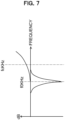
- FIG. 7 illustrates together the characteristic of the first filter processing unit 15x and the characteristic of the second filter processing unit 15y, which are combined to form an entire filter function.
- a filter is digitally configured with the use of a microcomputer. Specifically, a filter function combining the characteristics shown in FIG. 7 is tabulated, digital values are extracted from a table at a predetermined update pitch for a pulse signal output from the multiplier 15c and converted into analog data by a DA converter, and a voltage after filtering is applied to the piezoelectric element 13 through the drive circuit 15d.
- these filter processing units 15x and 15y may be configured to perform filtering by giving a calculation formula to a microcomputer, or may be configured by an analog circuit.
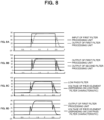
- FIG. 8(a) illustrates together an input waveform and an output waveform to the first filter processing unit 15x, and it is originally desirable to apply this output waveform to the piezoelectric element 13.
- a voltage waveform is once amplified by the second filter processing unit 15y as shown in FIG. 8(b).
- the final applied voltage waveform of the piezoelectric element 13 becomes as shown in FIG. 8(c), which corresponds to an output waveform from the first filtering unit as illustrated together in FIG. 8(d). That is, it is understood that a voltage can be applied to the piezoelectric element 13 with a voltage waveform that is output from the first filter processing unit 15x and originally desired to be applied while reducing an influence due to electrical characteristics.
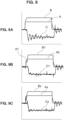
- FIG. 9 shows comparison data.
- FIG. 9(a) shows an applied voltage waveform B to the piezoelectric element 13 and a measured waveform of a displacement C of the valve 12 when a circuit is formed with a configuration in a case where the first and second filter processing units 15x and 15y shown in FIG. 2 are not present and the pulse output A is applied. How the valve is vibrating can be seen. Meanwhile, FIG. 9(a) shows an applied voltage waveform B to the piezoelectric element 13 and a measured waveform of a displacement C of the valve 12 when a circuit is formed with a configuration in a case where the first and second filter processing units 15x and 15y shown in FIG. 2 are not present and the pulse output A is applied. How the valve is vibrating can be seen. Meanwhile, FIG.
- FIG. 9(b) shows the applied voltage waveform B to the piezoelectric element 13 and a displacement C1 of a valve in a case where, in a stepwise driving method of cited document 1, a pulse signal A2 is input and a pulse signal A1 of a first stage as a voltage lower than the A2 is input in a previous state stepwise, and it can be seen that the vibration of the valve 12 is improved.
- FIG. 9(c) shows a measurement result of the present embodiment in a case where the first and second filter processing units 15x and 15y shown in FIG.
- Az is an output waveform through the first and second filter processing units 15x and 15y
- Bz is a voltage waveform applied to the piezoelectric element
- Cz is a displacement of the valve. It can be seen that a stable result is obtained for the displacement of the valve 12.
- the resonance vibration suppression can be further improved by speeding up the update pitch of the DA converter and bringing same closer to an analog waveform. However, even the illustrated state is sufficiently practical. While all the comparison data in FIG. 9 is confirmed only by an extension operation, a same effect is obtained in a reduction operation.
- the resonance frequency component of the piezoelectric actuator A is removed from the drive voltage applied to the piezoelectric element 13 by the notch filter of the first filter processing unit 15x, and thus vibration due to the mechanical resonance of the piezoelectric actuator A is eliminated and suppressed.
- the response speed can be increased.
- responsiveness can be further improved by an inverse function of a low pass filter composed of a driver and a load of the second filter processing unit 15y.
- the command voltage in the present embodiment is a pulse voltage obtained by multiplying, an output signal waveform (pulse waveform) generated by the output signal generator 15a by a voltage level value set by the output voltage setting unit 15b, by the multiplication unit 15c. Only a height of an entire pulse is changed by the multiplication, and a pulse waveform which is a voltage command is not changed as a first voltage and a second voltage in a stepwise manner in two steps or multiple stages in such a manner as in the prior art document 1, and in addition, a signal generation unit does not generate a signal separated into a prepulse and a main pulse in such a manner as in the prior art document 2.
- the controller which is the driving means includes the first filter processing unit and the second filter processing unit
- the operation and effect according to the above can be exhibited even with the first filter processing unit alone.
- the resonance suppression processing unit and the delay compensation processing unit are configured by the filter, it is also possible to implement these by a function not belonging to a concept of the filter.
- the present invention can be effectively used as a piezoelectric actuator and a piezoelectric valve which drive an object by enlarging a displacement of a piezoelectric element (piezo element).
Landscapes
- Engineering & Computer Science (AREA)
- General Engineering & Computer Science (AREA)
- Mechanical Engineering (AREA)
- Electrically Driven Valve-Operating Means (AREA)
- General Electrical Machinery Utilizing Piezoelectricity, Electrostriction Or Magnetostriction (AREA)
- Apparatuses For Generation Of Mechanical Vibrations (AREA)
Claims (4)
- Piezoelektrisches Stellglied (A), mit:einem piezoelektrischen Element (13), das konfiguriert ist, um als eine Auslenkung eine Antriebskraft zu erzeugen, die für eine Betätigung eines Betätigungskörpers (12) notwendig ist;einem Auslenkungsvergrößerungsmechanismus (14), der teilweise mindestens ein Federelement (19) umfasst, um eine Auslenkung des piezoelektrischen Elements (13) zu vergrößern, die auf den Betätigungskörper (12) wirkt; undeiner Antriebseinrichtung (15), die konfiguriert ist, um den Betätigungskörper (12) durch den Auslenkungsvergrößerungsmechanismus (14) zu betätigen, indem eine Spannung an das piezoelektrische Element (13) auf der Grundlage einer Spannungsanweisung einer Pulswellenform angelegt wird, um das piezoelektrische Element (13) auszudehnen,wobeidas Federelement (19) eine Federelastizität eines das piezoelektrische Stellglied bildenden Stellgliedkörpers darstellt,dadurch gekennzeichnet, dassdie Antriebseinrichtung (15) ein Kerbfilter (15x) als eine Verarbeitungseinheit zur Resonanzunterdrückung aufweist, die eine inverse Funktionscharakteristik einer mechanischen Resonanzfrequenz durch die Federelastizität aufweist, wenn der Auslenkungsvergrößerungsmechanismus (14) betätigt wird, und konfiguriert ist, um eine Spannung auf der Grundlage der Spannungsanweisung einer Pulswellenform, in der die mechanische Resonanz des Auslenkungsvergrößerungsmechanismus (14) reduziert wird, an das piezoelektrische Element (13) durch den Kerbfilter (15x) anzulegen, und zu bewirken, dass die Auslenkung des piezoelektrischen Elements (13) aufgrund dieser Spannung auf den Betätigungskörper (12) über den Auslenkungsvergrößerungsmechanismus (14) wirkt, wodurch die Schwingung des Stellgliedkörpers unterdrückt wird.
- Piezoelektrisches Stellglied (A) gemäß Anspruch 1, wobei die Antriebseinrichtung (15) eine Verzögerungskompensationsverarbeitungseinheit (15y) aufweist, die eine inverse Charakteristik einer elektrischen Antriebscharakteristik hat, die eine Verzögerung verursacht, wenn das piezoelektrische Element (13) angetrieben wird, und konfiguriert ist, um eine Spannung, die einen Einfluss der elektrischen Antriebscharakteristik reduziert, an das piezoelektrische Element (13) durch diese Verzögerungskompensationsverarbeitungseinheit (15y) anzulegen.
- Piezoelektrisches Stellglied (A) gemäß Anspruch 2, wobei die Verzögerungskompensationsverarbeitungseinheit (15y) ein Hochpassfilter ist.
- Piezoelektrisches Ventil (V) unter Verwendung des piezoelektrischen Stellglieds (A) gemäß den Ansprüchen 1 bis 3, wobei das piezoelektrische Ventil (V) aufweist:einen Ventilhauptkörper (11), in dem eine Gasdruckkammer (111), die von außen zugeführtes komprimiertes Gas aufnimmt, und ein Gasauslasskanal (112), der das komprimierte Gas aus der Gasdruckkammer (111) abführt, ausgebildet sind; undeinen Ventilkörper (12), der ein Betätigungskörper ist, der in der Gasdruckkammer (111) angeordnet ist und den Gasauslasskanal (112) öffnet und schließt.
Applications Claiming Priority (2)
| Application Number | Priority Date | Filing Date | Title |
|---|---|---|---|
| JP2016221198A JP6955137B2 (ja) | 2016-11-14 | 2016-11-14 | 圧電式アクチュエータ及び圧電式バルブ |
| PCT/JP2017/025659 WO2018087959A1 (ja) | 2016-11-14 | 2017-07-14 | 圧電式アクチュエータ及び圧電式バルブ |
Publications (3)
| Publication Number | Publication Date |
|---|---|
| EP3539680A1 EP3539680A1 (de) | 2019-09-18 |
| EP3539680A4 EP3539680A4 (de) | 2020-07-22 |
| EP3539680B1 true EP3539680B1 (de) | 2024-03-13 |
Family
ID=62109507
Family Applications (1)
| Application Number | Title | Priority Date | Filing Date |
|---|---|---|---|
| EP17869630.8A Active EP3539680B1 (de) | 2016-11-14 | 2017-07-14 | Piezoelektrischer aktuator und piezoelektrisches ventil |
Country Status (7)
| Country | Link |
|---|---|
| US (1) | US11009141B2 (de) |
| EP (1) | EP3539680B1 (de) |
| JP (1) | JP6955137B2 (de) |
| KR (1) | KR102338645B1 (de) |
| CN (1) | CN109982780B (de) |
| TW (1) | TWI735580B (de) |
| WO (1) | WO2018087959A1 (de) |
Families Citing this family (3)
| Publication number | Priority date | Publication date | Assignee | Title |
|---|---|---|---|---|
| JP7001296B2 (ja) * | 2020-01-08 | 2022-01-19 | 有限会社メカノトランスフォーマ | 変位拡大機構、アクチュエータ、研磨装置、電子部品処理装置、ディスペンサ、およびエアバルブ |
| JP2023040509A (ja) * | 2021-09-10 | 2023-03-23 | セイコーエプソン株式会社 | エンドエフェクター、ロボット、及びエンドエフェクターの制御方法 |
| CN116518133B (zh) * | 2023-05-30 | 2026-02-03 | 合肥工业大学 | 一种基于桥式放大机构的大流量气动压电阀 |
Family Cites Families (19)
| Publication number | Priority date | Publication date | Assignee | Title |
|---|---|---|---|---|
| JPS5631631B2 (de) | 1975-02-10 | 1981-07-22 | ||
| JPH0999567A (ja) * | 1995-10-04 | 1997-04-15 | Denso Corp | ピエゾアクチュエータ |
| JPH10288618A (ja) * | 1997-04-16 | 1998-10-27 | Seiko Instr Inc | 表面分析装置 |
| JP3975029B2 (ja) * | 1999-07-06 | 2007-09-12 | オリンパス株式会社 | 動吸振器付き走査型プローブ顕微鏡及びその測定方法 |
| JP4344164B2 (ja) * | 2003-04-18 | 2009-10-14 | 株式会社サタケ | 圧電式エアバルブおよび複合圧電式エアバルブ |
| JP2007028419A (ja) * | 2005-07-20 | 2007-02-01 | Victor Co Of Japan Ltd | スピーカ駆動装置 |
| US7849870B2 (en) * | 2007-11-01 | 2010-12-14 | Honeywell International Inc. | Piezoelectric pressure control valve |
| US20100326530A1 (en) * | 2007-11-01 | 2010-12-30 | Honeywell International, Inc. | Piezoelectric flow control valve |
| JP5348881B2 (ja) * | 2007-12-25 | 2013-11-20 | セミコンダクター・コンポーネンツ・インダストリーズ・リミテッド・ライアビリティ・カンパニー | 振動補償制御回路 |
| DE102009023318B3 (de) | 2009-05-29 | 2010-12-02 | Continental Automotive Gmbh | Schaltungsanordnung und Verfahren zum Betätigen eines Piezoventils |
| JP5740879B2 (ja) | 2009-09-18 | 2015-07-01 | 株式会社村田製作所 | 圧電アクチュエーター駆動回路 |
| JP2011143099A (ja) * | 2010-01-15 | 2011-07-28 | Asahi Kasei Electronics Co Ltd | 振動要素駆動回路および振動要素保護回路 |
| JP5631631B2 (ja) | 2010-05-21 | 2014-11-26 | 株式会社サタケ | 圧電式バルブ及び該圧電式バルブを利用する光学式粒状物選別機 |
| JP2013144273A (ja) * | 2012-01-13 | 2013-07-25 | Taiheiyo Cement Corp | 圧電アクチュエータの駆動回路 |
| US9114430B2 (en) | 2012-04-20 | 2015-08-25 | Satake Corporation | Piezoelectric valve, and optical particulate matter sorter provided with air-blowing means that uses piezoelectric valve |
| JP2014127533A (ja) | 2012-12-25 | 2014-07-07 | Nikon Corp | 搬送装置、基板貼り合わせ装置および搬送装置駆動プログラム |
| DE102013105557B4 (de) * | 2013-05-29 | 2015-06-11 | Michael Förg | Piezoelektrischer Aktor |
| JP6285689B2 (ja) * | 2013-10-31 | 2018-02-28 | ローム株式会社 | アクチュエータの駆動回路装置及び駆動方法並びにそれらを用いたレンズモジュール及び電子機器 |
| JP2016032939A (ja) * | 2015-09-25 | 2016-03-10 | セイコーエプソン株式会社 | 制御装置および流体噴射装置 |
-
2016
- 2016-11-14 JP JP2016221198A patent/JP6955137B2/ja active Active
-
2017
- 2017-05-24 TW TW106117224A patent/TWI735580B/zh active
- 2017-07-14 WO PCT/JP2017/025659 patent/WO2018087959A1/ja not_active Ceased
- 2017-07-14 EP EP17869630.8A patent/EP3539680B1/de active Active
- 2017-07-14 KR KR1020197011814A patent/KR102338645B1/ko active Active
- 2017-07-14 US US16/349,407 patent/US11009141B2/en active Active
- 2017-07-14 CN CN201780069881.4A patent/CN109982780B/zh active Active
Also Published As
| Publication number | Publication date |
|---|---|
| JP2018080709A (ja) | 2018-05-24 |
| US11009141B2 (en) | 2021-05-18 |
| EP3539680A4 (de) | 2020-07-22 |
| WO2018087959A1 (ja) | 2018-05-17 |
| EP3539680A1 (de) | 2019-09-18 |
| KR102338645B1 (ko) | 2021-12-13 |
| JP6955137B2 (ja) | 2021-10-27 |
| TW201818012A (zh) | 2018-05-16 |
| US20190264827A1 (en) | 2019-08-29 |
| KR20190080870A (ko) | 2019-07-08 |
| CN109982780B (zh) | 2021-10-01 |
| TWI735580B (zh) | 2021-08-11 |
| CN109982780A (zh) | 2019-07-05 |
Similar Documents
| Publication | Publication Date | Title |
|---|---|---|
| EP3539680B1 (de) | Piezoelektrischer aktuator und piezoelektrisches ventil | |
| Sebald et al. | Simulation of a Duffing oscillator for broadband piezoelectric energy harvesting | |
| EP2178208A2 (de) | Systeme und Verfahren zum Überwinden von Gleichstromverzögerung bei Verstärkern, die zum Starten von resonanten mikroelektrischen mechanischen Systemen verwendet werden | |
| EP3136751B1 (de) | Mems-lautsprecher mit positionssensor | |
| CN107925834B (zh) | 具有封闭控制系统的mems声换能器 | |
| KR101602672B1 (ko) | 피에조 밸브를 작동시키기 위한 회로 어레인지먼트 및 방법 | |
| JP2014503169A (ja) | 機械/電気変換装置による振動エネルギーの変換を最適化する回路 | |
| US6340858B1 (en) | Method for calibrating a piezoelectric actuating drive | |
| CN108282730A (zh) | 微机械声换能器组件和相应的制造方法 | |
| CN102447419A (zh) | 控制装置、微系统装置和用于控制微机械致动器的方法 | |
| US20220377466A1 (en) | Microphone | |
| US6950050B1 (en) | Method and apparatus for increasing effective resolution of analog output of digital-to-analog converter (DAC) having predetermined digital word size, where DAC drives plant | |
| JP5879197B2 (ja) | 静電型変換装置、静電型トランスおよび交流電圧発生装置 | |
| JP7529138B2 (ja) | 音波発生装置 | |
| CN108352438A (zh) | 操控电路和用于操控压电变压器的方法 | |
| JP4039721B2 (ja) | 電磁比例制御弁の制御装置および制御回路 | |
| JP6339252B2 (ja) | 発振制御装置および発振装置 | |
| JP2022029016A (ja) | 振動型モータの制御装置 | |
| JP7352281B2 (ja) | 動吸振器 | |
| Yokozawa et al. | Dynamic control of transducer's resonant frequency via the controlling of electric terminal | |
| Agrawal et al. | Modelling non-linearities in a MEMS square wave oscillator | |
| Nam et al. | Experiments on the vibration suppression of a piezoelectric beam using a self-sensing mechanism | |
| Khater et al. | Transient response enhancement of RF MEMS tuners using digital signal processing | |
| Sobreviela et al. | Nonlinear behavior of the capacitively coupled NEMS resonator operating close to the nonlinear regime cancellation | |
| JP2005245088A (ja) | モータ制御装置 |
Legal Events
| Date | Code | Title | Description |
|---|---|---|---|
| STAA | Information on the status of an ep patent application or granted ep patent |
Free format text: STATUS: THE INTERNATIONAL PUBLICATION HAS BEEN MADE |
|
| PUAI | Public reference made under article 153(3) epc to a published international application that has entered the european phase |
Free format text: ORIGINAL CODE: 0009012 |
|
| STAA | Information on the status of an ep patent application or granted ep patent |
Free format text: STATUS: REQUEST FOR EXAMINATION WAS MADE |
|
| 17P | Request for examination filed |
Effective date: 20190507 |
|
| AK | Designated contracting states |
Kind code of ref document: A1 Designated state(s): AL AT BE BG CH CY CZ DE DK EE ES FI FR GB GR HR HU IE IS IT LI LT LU LV MC MK MT NL NO PL PT RO RS SE SI SK SM TR |
|
| AX | Request for extension of the european patent |
Extension state: BA ME |
|
| DAV | Request for validation of the european patent (deleted) | ||
| DAX | Request for extension of the european patent (deleted) | ||
| REG | Reference to a national code |
Ref country code: DE Ref legal event code: R079 Ipc: F16K0031020000 Ref country code: DE Ref legal event code: R079 Ref document number: 602017080080 Country of ref document: DE Free format text: PREVIOUS MAIN CLASS: B06B0001060000 Ipc: F16K0031020000 |
|
| A4 | Supplementary search report drawn up and despatched |
Effective date: 20200619 |
|
| RIC1 | Information provided on ipc code assigned before grant |
Ipc: H02N 2/14 20060101ALI20200615BHEP Ipc: H02N 2/06 20060101ALI20200615BHEP Ipc: F16K 31/02 20060101AFI20200615BHEP |
|
| STAA | Information on the status of an ep patent application or granted ep patent |
Free format text: STATUS: EXAMINATION IS IN PROGRESS |
|
| 17Q | First examination report despatched |
Effective date: 20220627 |
|
| P01 | Opt-out of the competence of the unified patent court (upc) registered |
Effective date: 20230426 |
|
| REG | Reference to a national code |
Free format text: PREVIOUS MAIN CLASS: F16K0031020000 Ref country code: DE Ref legal event code: R079 Ref document number: 602017080080 Country of ref document: DE Free format text: PREVIOUS MAIN CLASS: F16K0031020000 Ipc: F16K0031000000 |
|
| GRAP | Despatch of communication of intention to grant a patent |
Free format text: ORIGINAL CODE: EPIDOSNIGR1 |
|
| STAA | Information on the status of an ep patent application or granted ep patent |
Free format text: STATUS: GRANT OF PATENT IS INTENDED |
|
| RIC1 | Information provided on ipc code assigned before grant |
Ipc: H02N 2/06 20060101ALI20231016BHEP Ipc: H02N 2/04 20060101ALI20231016BHEP Ipc: F16K 31/00 20060101AFI20231016BHEP |
|
| INTG | Intention to grant announced |
Effective date: 20231031 |
|
| GRAS | Grant fee paid |
Free format text: ORIGINAL CODE: EPIDOSNIGR3 |
|
| GRAA | (expected) grant |
Free format text: ORIGINAL CODE: 0009210 |
|
| STAA | Information on the status of an ep patent application or granted ep patent |
Free format text: STATUS: THE PATENT HAS BEEN GRANTED |
|
| AK | Designated contracting states |
Kind code of ref document: B1 Designated state(s): AL AT BE BG CH CY CZ DE DK EE ES FI FR GB GR HR HU IE IS IT LI LT LU LV MC MK MT NL NO PL PT RO RS SE SI SK SM TR |
|
| REG | Reference to a national code |
Ref country code: GB Ref legal event code: FG4D |
|
| REG | Reference to a national code |
Ref country code: CH Ref legal event code: EP |
|
| REG | Reference to a national code |
Ref country code: DE Ref legal event code: R096 Ref document number: 602017080080 Country of ref document: DE |
|
| REG | Reference to a national code |
Ref country code: IE Ref legal event code: FG4D |
|
| PG25 | Lapsed in a contracting state [announced via postgrant information from national office to epo] |
Ref country code: LT Free format text: LAPSE BECAUSE OF FAILURE TO SUBMIT A TRANSLATION OF THE DESCRIPTION OR TO PAY THE FEE WITHIN THE PRESCRIBED TIME-LIMIT Effective date: 20240313 |
|
| REG | Reference to a national code |
Ref country code: LT Ref legal event code: MG9D |
|
| PG25 | Lapsed in a contracting state [announced via postgrant information from national office to epo] |
Ref country code: GR Free format text: LAPSE BECAUSE OF FAILURE TO SUBMIT A TRANSLATION OF THE DESCRIPTION OR TO PAY THE FEE WITHIN THE PRESCRIBED TIME-LIMIT Effective date: 20240614 |
|
| REG | Reference to a national code |
Ref country code: NL Ref legal event code: MP Effective date: 20240313 |
|
| PG25 | Lapsed in a contracting state [announced via postgrant information from national office to epo] |
Ref country code: HR Free format text: LAPSE BECAUSE OF FAILURE TO SUBMIT A TRANSLATION OF THE DESCRIPTION OR TO PAY THE FEE WITHIN THE PRESCRIBED TIME-LIMIT Effective date: 20240313 Ref country code: RS Free format text: LAPSE BECAUSE OF FAILURE TO SUBMIT A TRANSLATION OF THE DESCRIPTION OR TO PAY THE FEE WITHIN THE PRESCRIBED TIME-LIMIT Effective date: 20240613 |
|
| PG25 | Lapsed in a contracting state [announced via postgrant information from national office to epo] |
Ref country code: ES Free format text: LAPSE BECAUSE OF FAILURE TO SUBMIT A TRANSLATION OF THE DESCRIPTION OR TO PAY THE FEE WITHIN THE PRESCRIBED TIME-LIMIT Effective date: 20240313 |
|
| PG25 | Lapsed in a contracting state [announced via postgrant information from national office to epo] |
Ref country code: RS Free format text: LAPSE BECAUSE OF FAILURE TO SUBMIT A TRANSLATION OF THE DESCRIPTION OR TO PAY THE FEE WITHIN THE PRESCRIBED TIME-LIMIT Effective date: 20240613 Ref country code: NO Free format text: LAPSE BECAUSE OF FAILURE TO SUBMIT A TRANSLATION OF THE DESCRIPTION OR TO PAY THE FEE WITHIN THE PRESCRIBED TIME-LIMIT Effective date: 20240613 Ref country code: LT Free format text: LAPSE BECAUSE OF FAILURE TO SUBMIT A TRANSLATION OF THE DESCRIPTION OR TO PAY THE FEE WITHIN THE PRESCRIBED TIME-LIMIT Effective date: 20240313 Ref country code: HR Free format text: LAPSE BECAUSE OF FAILURE TO SUBMIT A TRANSLATION OF THE DESCRIPTION OR TO PAY THE FEE WITHIN THE PRESCRIBED TIME-LIMIT Effective date: 20240313 Ref country code: GR Free format text: LAPSE BECAUSE OF FAILURE TO SUBMIT A TRANSLATION OF THE DESCRIPTION OR TO PAY THE FEE WITHIN THE PRESCRIBED TIME-LIMIT Effective date: 20240614 Ref country code: FI Free format text: LAPSE BECAUSE OF FAILURE TO SUBMIT A TRANSLATION OF THE DESCRIPTION OR TO PAY THE FEE WITHIN THE PRESCRIBED TIME-LIMIT Effective date: 20240313 Ref country code: ES Free format text: LAPSE BECAUSE OF FAILURE TO SUBMIT A TRANSLATION OF THE DESCRIPTION OR TO PAY THE FEE WITHIN THE PRESCRIBED TIME-LIMIT Effective date: 20240313 Ref country code: BG Free format text: LAPSE BECAUSE OF FAILURE TO SUBMIT A TRANSLATION OF THE DESCRIPTION OR TO PAY THE FEE WITHIN THE PRESCRIBED TIME-LIMIT Effective date: 20240313 |
|
| REG | Reference to a national code |
Ref country code: AT Ref legal event code: MK05 Ref document number: 1666037 Country of ref document: AT Kind code of ref document: T Effective date: 20240313 |
|
| PG25 | Lapsed in a contracting state [announced via postgrant information from national office to epo] |
Ref country code: SE Free format text: LAPSE BECAUSE OF FAILURE TO SUBMIT A TRANSLATION OF THE DESCRIPTION OR TO PAY THE FEE WITHIN THE PRESCRIBED TIME-LIMIT Effective date: 20240313 Ref country code: LV Free format text: LAPSE BECAUSE OF FAILURE TO SUBMIT A TRANSLATION OF THE DESCRIPTION OR TO PAY THE FEE WITHIN THE PRESCRIBED TIME-LIMIT Effective date: 20240313 |
|
| PG25 | Lapsed in a contracting state [announced via postgrant information from national office to epo] |
Ref country code: NL Free format text: LAPSE BECAUSE OF FAILURE TO SUBMIT A TRANSLATION OF THE DESCRIPTION OR TO PAY THE FEE WITHIN THE PRESCRIBED TIME-LIMIT Effective date: 20240313 |
|
| PG25 | Lapsed in a contracting state [announced via postgrant information from national office to epo] |
Ref country code: NL Free format text: LAPSE BECAUSE OF FAILURE TO SUBMIT A TRANSLATION OF THE DESCRIPTION OR TO PAY THE FEE WITHIN THE PRESCRIBED TIME-LIMIT Effective date: 20240313 |
|
| PG25 | Lapsed in a contracting state [announced via postgrant information from national office to epo] |
Ref country code: IS Free format text: LAPSE BECAUSE OF FAILURE TO SUBMIT A TRANSLATION OF THE DESCRIPTION OR TO PAY THE FEE WITHIN THE PRESCRIBED TIME-LIMIT Effective date: 20240713 |
|
| PG25 | Lapsed in a contracting state [announced via postgrant information from national office to epo] |
Ref country code: SM Free format text: LAPSE BECAUSE OF FAILURE TO SUBMIT A TRANSLATION OF THE DESCRIPTION OR TO PAY THE FEE WITHIN THE PRESCRIBED TIME-LIMIT Effective date: 20240313 Ref country code: PT Free format text: LAPSE BECAUSE OF FAILURE TO SUBMIT A TRANSLATION OF THE DESCRIPTION OR TO PAY THE FEE WITHIN THE PRESCRIBED TIME-LIMIT Effective date: 20240715 |
|
| PG25 | Lapsed in a contracting state [announced via postgrant information from national office to epo] |
Ref country code: CZ Free format text: LAPSE BECAUSE OF FAILURE TO SUBMIT A TRANSLATION OF THE DESCRIPTION OR TO PAY THE FEE WITHIN THE PRESCRIBED TIME-LIMIT Effective date: 20240313 Ref country code: EE Free format text: LAPSE BECAUSE OF FAILURE TO SUBMIT A TRANSLATION OF THE DESCRIPTION OR TO PAY THE FEE WITHIN THE PRESCRIBED TIME-LIMIT Effective date: 20240313 |
|
| PG25 | Lapsed in a contracting state [announced via postgrant information from national office to epo] |
Ref country code: AT Free format text: LAPSE BECAUSE OF FAILURE TO SUBMIT A TRANSLATION OF THE DESCRIPTION OR TO PAY THE FEE WITHIN THE PRESCRIBED TIME-LIMIT Effective date: 20240313 |
|
| PG25 | Lapsed in a contracting state [announced via postgrant information from national office to epo] |
Ref country code: PL Free format text: LAPSE BECAUSE OF FAILURE TO SUBMIT A TRANSLATION OF THE DESCRIPTION OR TO PAY THE FEE WITHIN THE PRESCRIBED TIME-LIMIT Effective date: 20240313 |
|
| PG25 | Lapsed in a contracting state [announced via postgrant information from national office to epo] |
Ref country code: SK Free format text: LAPSE BECAUSE OF FAILURE TO SUBMIT A TRANSLATION OF THE DESCRIPTION OR TO PAY THE FEE WITHIN THE PRESCRIBED TIME-LIMIT Effective date: 20240313 |
|
| PG25 | Lapsed in a contracting state [announced via postgrant information from national office to epo] |
Ref country code: SM Free format text: LAPSE BECAUSE OF FAILURE TO SUBMIT A TRANSLATION OF THE DESCRIPTION OR TO PAY THE FEE WITHIN THE PRESCRIBED TIME-LIMIT Effective date: 20240313 Ref country code: SK Free format text: LAPSE BECAUSE OF FAILURE TO SUBMIT A TRANSLATION OF THE DESCRIPTION OR TO PAY THE FEE WITHIN THE PRESCRIBED TIME-LIMIT Effective date: 20240313 Ref country code: RO Free format text: LAPSE BECAUSE OF FAILURE TO SUBMIT A TRANSLATION OF THE DESCRIPTION OR TO PAY THE FEE WITHIN THE PRESCRIBED TIME-LIMIT Effective date: 20240313 Ref country code: PT Free format text: LAPSE BECAUSE OF FAILURE TO SUBMIT A TRANSLATION OF THE DESCRIPTION OR TO PAY THE FEE WITHIN THE PRESCRIBED TIME-LIMIT Effective date: 20240715 Ref country code: PL Free format text: LAPSE BECAUSE OF FAILURE TO SUBMIT A TRANSLATION OF THE DESCRIPTION OR TO PAY THE FEE WITHIN THE PRESCRIBED TIME-LIMIT Effective date: 20240313 Ref country code: IS Free format text: LAPSE BECAUSE OF FAILURE TO SUBMIT A TRANSLATION OF THE DESCRIPTION OR TO PAY THE FEE WITHIN THE PRESCRIBED TIME-LIMIT Effective date: 20240713 Ref country code: EE Free format text: LAPSE BECAUSE OF FAILURE TO SUBMIT A TRANSLATION OF THE DESCRIPTION OR TO PAY THE FEE WITHIN THE PRESCRIBED TIME-LIMIT Effective date: 20240313 Ref country code: CZ Free format text: LAPSE BECAUSE OF FAILURE TO SUBMIT A TRANSLATION OF THE DESCRIPTION OR TO PAY THE FEE WITHIN THE PRESCRIBED TIME-LIMIT Effective date: 20240313 Ref country code: AT Free format text: LAPSE BECAUSE OF FAILURE TO SUBMIT A TRANSLATION OF THE DESCRIPTION OR TO PAY THE FEE WITHIN THE PRESCRIBED TIME-LIMIT Effective date: 20240313 |
|
| PG25 | Lapsed in a contracting state [announced via postgrant information from national office to epo] |
Ref country code: IT Free format text: LAPSE BECAUSE OF FAILURE TO SUBMIT A TRANSLATION OF THE DESCRIPTION OR TO PAY THE FEE WITHIN THE PRESCRIBED TIME-LIMIT Effective date: 20240313 |
|
| REG | Reference to a national code |
Ref country code: DE Ref legal event code: R097 Ref document number: 602017080080 Country of ref document: DE |
|
| PG25 | Lapsed in a contracting state [announced via postgrant information from national office to epo] |
Ref country code: IT Free format text: LAPSE BECAUSE OF FAILURE TO SUBMIT A TRANSLATION OF THE DESCRIPTION OR TO PAY THE FEE WITHIN THE PRESCRIBED TIME-LIMIT Effective date: 20240313 |
|
| PG25 | Lapsed in a contracting state [announced via postgrant information from national office to epo] |
Ref country code: DK Free format text: LAPSE BECAUSE OF FAILURE TO SUBMIT A TRANSLATION OF THE DESCRIPTION OR TO PAY THE FEE WITHIN THE PRESCRIBED TIME-LIMIT Effective date: 20240313 |
|
| PLBE | No opposition filed within time limit |
Free format text: ORIGINAL CODE: 0009261 |
|
| STAA | Information on the status of an ep patent application or granted ep patent |
Free format text: STATUS: NO OPPOSITION FILED WITHIN TIME LIMIT |
|
| PG25 | Lapsed in a contracting state [announced via postgrant information from national office to epo] |
Ref country code: DK Free format text: LAPSE BECAUSE OF FAILURE TO SUBMIT A TRANSLATION OF THE DESCRIPTION OR TO PAY THE FEE WITHIN THE PRESCRIBED TIME-LIMIT Effective date: 20240313 |
|
| PG25 | Lapsed in a contracting state [announced via postgrant information from national office to epo] |
Ref country code: MC Free format text: LAPSE BECAUSE OF FAILURE TO SUBMIT A TRANSLATION OF THE DESCRIPTION OR TO PAY THE FEE WITHIN THE PRESCRIBED TIME-LIMIT Effective date: 20240313 |
|
| 26N | No opposition filed |
Effective date: 20241216 |
|
| REG | Reference to a national code |
Ref country code: CH Ref legal event code: PL |
|
| PG25 | Lapsed in a contracting state [announced via postgrant information from national office to epo] |
Ref country code: LU Free format text: LAPSE BECAUSE OF NON-PAYMENT OF DUE FEES Effective date: 20240714 |
|
| GBPC | Gb: european patent ceased through non-payment of renewal fee |
Effective date: 20240714 |
|
| PG25 | Lapsed in a contracting state [announced via postgrant information from national office to epo] |
Ref country code: LU Free format text: LAPSE BECAUSE OF NON-PAYMENT OF DUE FEES Effective date: 20240714 |
|
| PG25 | Lapsed in a contracting state [announced via postgrant information from national office to epo] |
Ref country code: SI Free format text: LAPSE BECAUSE OF FAILURE TO SUBMIT A TRANSLATION OF THE DESCRIPTION OR TO PAY THE FEE WITHIN THE PRESCRIBED TIME-LIMIT Effective date: 20240313 Ref country code: CH Free format text: LAPSE BECAUSE OF NON-PAYMENT OF DUE FEES Effective date: 20240731 Ref country code: BE Free format text: LAPSE BECAUSE OF NON-PAYMENT OF DUE FEES Effective date: 20240731 |
|
| PG25 | Lapsed in a contracting state [announced via postgrant information from national office to epo] |
Ref country code: FR Free format text: LAPSE BECAUSE OF NON-PAYMENT OF DUE FEES Effective date: 20240731 |
|
| PG25 | Lapsed in a contracting state [announced via postgrant information from national office to epo] |
Ref country code: GB Free format text: LAPSE BECAUSE OF NON-PAYMENT OF DUE FEES Effective date: 20240714 |
|
| REG | Reference to a national code |
Ref country code: BE Ref legal event code: MM Effective date: 20240731 |
|
| PG25 | Lapsed in a contracting state [announced via postgrant information from national office to epo] |
Ref country code: IE Free format text: LAPSE BECAUSE OF NON-PAYMENT OF DUE FEES Effective date: 20240714 |
|
| PGFP | Annual fee paid to national office [announced via postgrant information from national office to epo] |
Ref country code: DE Payment date: 20250722 Year of fee payment: 9 |
|
| PG25 | Lapsed in a contracting state [announced via postgrant information from national office to epo] |
Ref country code: CY Free format text: LAPSE BECAUSE OF FAILURE TO SUBMIT A TRANSLATION OF THE DESCRIPTION OR TO PAY THE FEE WITHIN THE PRESCRIBED TIME-LIMIT; INVALID AB INITIO Effective date: 20170714 |