EP3538014B1 - Schutzüberzug für ein teil eines medizingeräts - Google Patents
Schutzüberzug für ein teil eines medizingeräts Download PDFInfo
- Publication number
- EP3538014B1 EP3538014B1 EP17829123.3A EP17829123A EP3538014B1 EP 3538014 B1 EP3538014 B1 EP 3538014B1 EP 17829123 A EP17829123 A EP 17829123A EP 3538014 B1 EP3538014 B1 EP 3538014B1
- Authority
- EP
- European Patent Office
- Prior art keywords
- handle
- protective device
- locking
- region
- rigid part
- Prior art date
- Legal status (The legal status is an assumption and is not a legal conclusion. Google has not performed a legal analysis and makes no representation as to the accuracy of the status listed.)
- Active
Links
Images






Classifications
-
- A—HUMAN NECESSITIES
- A61—MEDICAL OR VETERINARY SCIENCE; HYGIENE
- A61B—DIAGNOSIS; SURGERY; IDENTIFICATION
- A61B46/00—Surgical drapes
- A61B46/10—Surgical drapes specially adapted for instruments, e.g. microscopes
-
- A—HUMAN NECESSITIES
- A61—MEDICAL OR VETERINARY SCIENCE; HYGIENE
- A61B—DIAGNOSIS; SURGERY; IDENTIFICATION
- A61B90/00—Instruments, implements or accessories specially adapted for surgery or diagnosis and not covered by any of the groups A61B1/00 - A61B50/00, e.g. for luxation treatment or for protecting wound edges
- A61B90/08—Accessories or related features not otherwise provided for
-
- A—HUMAN NECESSITIES
- A61—MEDICAL OR VETERINARY SCIENCE; HYGIENE
- A61B—DIAGNOSIS; SURGERY; IDENTIFICATION
- A61B46/00—Surgical drapes
-
- A—HUMAN NECESSITIES
- A61—MEDICAL OR VETERINARY SCIENCE; HYGIENE
- A61B—DIAGNOSIS; SURGERY; IDENTIFICATION
- A61B90/00—Instruments, implements or accessories specially adapted for surgery or diagnosis and not covered by any of the groups A61B1/00 - A61B50/00, e.g. for luxation treatment or for protecting wound edges
- A61B90/03—Automatic limiting or abutting means, e.g. for safety
- A61B2090/037—Automatic limiting or abutting means, e.g. for safety with a frangible part, e.g. by reduced diameter
-
- A—HUMAN NECESSITIES
- A61—MEDICAL OR VETERINARY SCIENCE; HYGIENE
- A61B—DIAGNOSIS; SURGERY; IDENTIFICATION
- A61B90/00—Instruments, implements or accessories specially adapted for surgery or diagnosis and not covered by any of the groups A61B1/00 - A61B50/00, e.g. for luxation treatment or for protecting wound edges
- A61B90/08—Accessories or related features not otherwise provided for
- A61B2090/0814—Preventing re-use
-
- A—HUMAN NECESSITIES
- A61—MEDICAL OR VETERINARY SCIENCE; HYGIENE
- A61B—DIAGNOSIS; SURGERY; IDENTIFICATION
- A61B90/00—Instruments, implements or accessories specially adapted for surgery or diagnosis and not covered by any of the groups A61B1/00 - A61B50/00, e.g. for luxation treatment or for protecting wound edges
- A61B90/30—Devices for illuminating a surgical field, the devices having an interrelation with other surgical devices or with a surgical procedure
- A61B2090/308—Lamp handles
Definitions
- the invention relates to a device (protective device) acting as a protective covering for a part of a medical device, in particular for a handle of a medical device, for example a lamp intended for use in an operating room (OP lamp).
- a device protecting device acting as a protective covering for a part of a medical device, in particular for a handle of a medical device, for example a lamp intended for use in an operating room (OP lamp).
- OP lamp operating room
- Medical devices and thus also medical devices intended for use in an operating room often have to be manually adjusted or adjusted by medical personnel during use, for example during an operation.
- medical devices have handles or the like that must be sterile to prevent transmission of infection from a user to a patient or vice versa.
- handles are usually changed before each operation, for example, or a protective device in the form of a sterile cover for single use or in the form of a single-use cover is attached to the handle.
- Such single-use covers usually consist of a plastic bag that is pushed over the respective handle. At the open end, the bag is held open by a stable portion.
- the protective device is often connected to the handle in a non-positive or positive manner by means of the stable portion. Additionally or alternatively, a vacuum resulting from the placement of a protective device on the respective handle is also used to hold it on the handle, in that a good seal prevents an inflow of air into the interior of the protective device.
- D1 shows a fastening device (lighting fixture 10) for a lighting device (surgical lighting) which a surgeon 16 can use.
- An assembly 14 having a handle 18 and a sterile disposable cover 20 is disposed on a body 12 .
- the handle 18 has a grip portion (handle grip portion 26) and a base portion (central stud 24, adapter 22) with a peripheral rigid disk 36, another rigid disk 38 and a peripheral recess 42.
- the cover 20 includes an elastic cover 52 over the handle portion 26, a rigid circumferential flange (cover flange 58) and four hook-shaped projections 62 which can engage in the recess 42.
- EP 3056164 A1 shows a protective device for a lamp 10 which can illuminate an operating room.
- a user may rotate a knob (knob 42). This rotation rotates a base 40 having a platform 52 .
- Actuating elements 114 are embedded in the base part 40 .
- a cover 44 has a portion 100 for the lever 42 and another portion 102 for the platform 52. To secure the cover 44, a spring loaded lever 406 engages a corresponding recess 404.
- one object of the present invention is to specify a protective device with the features of the preamble of claim 1 for a handle of a medical device, which is characterized by improvements with regard to one or more of the disadvantages mentioned.
- a protective device for a handle of a medical device provides that the protective device comprises a first, flexible part and a second, fixed part, that the flexible part completely covers at least one grip area of the handle in the case of a protective device attached to the handle, that the fixed part is releasably engaged with a base portion of the handle and that the fixed part comprises at least one locking element for releasably fixing to the base portion.
- the protective device proposed here for a handle of a medical device therefore comprises a fixed part designed to fix the protective device to the handle and a flexible bag-like or bag-like part designed to cover at least the gripping area of the handle, with both parts being connected to one another and with the fixed part at least one Having a locking element that can be releasably connected to a counterpart of the handle, for example, can be releasably connected in a detent manner.
- Typical medical devices on the handles of which such a protective device can advantageously be used are, for example, surgical lights (OP lights) and monitor mounts.
- An advantage of the innovation is that the protective device can be attached and fixed to the respective handle easily, in particular with just one hand, without the need to touch the surroundings of the handle and the medical device itself and thus non-sterile parts must.
- the division into a flexible part and a fixed part results in an advantageously small pack size, with the fixed part essentially determining the required volume.
- the protective device has in its fixed part a thread or profile intended to interact with a thread or profile in the base area of the respective handle.
- the profile on the fixed part and the profile on the base part are designed in the form or in the manner of a bayonet lock. A particularly secure fixing of the protective device on the respective handle can be ensured by means of such a thread or profile.
- the protective device has turning aids on its fixed part. Such turning aids facilitate the turning movement of the fixed part relative to the base area of the handle, which is necessary for fixing the protective device on the respective handle.
- the fixing of the protective device on the respective handle can be undone in a particularly easy and uncomplicated manner if the protective device has an unlocking device on the fixed part for releasing the locking element from a fixing in the base area of the handle.
- the protective device has at least one predetermined breaking point spatially associated with the unlocking device on the fixed part.
- the predetermined breaking point or at least one predetermined breaking point yields, resulting in irreversible deformation of the fixed part of the protective device.
- it can be reliably recognized at any time whether the protective device was already in use. Unintended multiple use of the protective device can thus be effectively prevented.
- a special embodiment of the protective device is characterized by a rigid, plate-shaped fixed part.
- the fixed part is particularly well adapted to the usual shape of a base area of a handle on a medical device.
- the plate-shaped, fixed part can be attached particularly well to the base area and thus the protective device can be attached particularly well overall to the handle.
- a fixed part is also referred to below as a mounting plate.
- the plate shape - ie the round shape - of the fixed part also ensures good all-round guidance of the flexible part through the fixed part, so that the flexible part at one
- the protective device attached to the handle fits snugly against the grip area of the handle on all sides.
- the protective device comprises a clamp, which is connected to the flexible part at least in some areas, as a fixed part.
- a clamp is elastically movable within the scope of its material properties and, when compressed, allows the flexible part connected to the clamp to be opened, for example.
- the clip is a flat component and accordingly the packaging size for the protective device when not in use is advantageously small, with the clip essentially determining the required base area of the packaging.
- this has at least one locking hook that acts as a locking element for releasably fixing the protective device to a respective handle on the clip, which hook engages in a locking area of the handle when it is fixed to the handle.
- a protective device with a clamp as a fixed part this has two brackets articulated on the clamp and connected at least in sections to the flexible part in its edge area. These brackets open the flexible part in a defined manner when the clip is pressed together and also hold the flexible part on all sides at its edges, so that the flexible part rests well on all sides at least on the grip area of a protective device attached to a handle.
- the innovation proposed here is also a system which includes a protective device of the type described here and below and a handle of a medical device, the handle having a handle area and a base area.
- the base area of the handle is designed for releasably fixing the fixed part of the protective device on the handle and has at least one locking area for receiving the locking element of the protective device.
- At least one predetermined breaking point is preferably provided and designed in such a way that it breaks when the protective device is unlocked, thus clearly indicating that the protective device has already been used and preventing the device from being used again.
- the locking area has a joining area, a latching area and, in between, a run-on area with a run-on bevel.
- the mating area is designed to receive the locking member of the guard when the guard is connected to the handle and receives the locking member when the guard is initially connected to the handle.
- the locking element of the protective device can be deflected by means of the starting bevel when connecting the protective device to the handle and when rotating the fixed part relative to the base area of the handle and is deflected when connecting the protective device to the handle and when rotating the fixed part relative to the base area of the handle. When the fixed part is rotated further, the locking element moves from the starting bevel into the locking area and is effective there for the locking fixation of the fixed part on the base area of the handle.
- the representation in figure 1 shows an example of an embodiment of the protective device 10 proposed here for a handle 12 ( 2 ) of a medical device that is not shown itself, for example a medical device in the form of an operating room light or a monitor recording.
- the protective device 10 comprises two parts connected to one another, namely a first, flexible part 14, which is slipped over the handle 12 and is referred to below as a bag 14 for short (but could also be referred to as a bag, for example), and a second, fixed (rigid) part 16, by means of which the protective device 10 is fixed to the respective handle 12 and which is referred to below as the mounting plate 16.
- the mounting plate 16 and the bag 14 are preferably made of a plastic.
- the bag 14 is firmly connected to the mounting plate 16 .
- the connection can be provided, for example, by welding, gluing or by clamping by means of a suitable additional component.
- the handle 12 has a handle area 20 and a base area 22 . At least the grip area 20 of the handle 12 is completely covered by the bag 14 of the protective device 10 in the case of a protective device 10 attached to the handle 12 .
- the protective device 10 removed from a sterile packaging is detachably connected to the handle 12 in that the bag 14 is slipped over the handle area 20 and the mounting plate 16 is detachably attached to the base area 22 .
- the protective device 10 has optional turning aids 18 on the mounting plate 16, in or on which the fingers of a user find support in order to turn the mounting plate 16 of the protective device 10 when it is attached to the respective medical device.
- These turning aids 18 can be raised and/or sunk in relation to the adjacent surface of the mounting plate 16 .
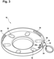
- the representation in figure 3 shows the underside of the mounting plate 16.
- the protective device 10 can be positively connected to the handle 12 of the respective medical device by means of a profile or thread 24 that can be seen in the mounting plate 16 and is positively connected to the handle 12 when it is attached to it.
- the handle 12 or the medical device have a profile or thread 26 corresponding to the profile or thread 24 of the protective device 10 ( 2 ) on.
- the thread 24 in the mounting plate 16 and the thread 26 on the base area 22 of the handle 12 do not necessarily have to be a continuous helical thread 24, 26 running around. In fact, matching, short helix sections are sufficient for a positive connection, as is the case in the illustrated embodiment.
- a profile in the manner of a bayonet catch or in the form of a bayonet catch can be considered as a profile for a form-fitting connection.
- the description presented here is continued using the example of a thread 24 (internal thread), in particular an internal thread 24 in the form of several short helical line sections, on the side of the mounting plate 16 and a matching thread 26 on the side of the handle 12 or the medical device .
- Other form-fitting connection options in particular a connection in the form of or in the manner of a bayonet lock, should always be read and expressly considered to be included in the description presented here.
- the mounting plate 16 of the protective device 10 comprises a locking element 28 which, in the embodiment shown, is in the form of a locking tab ( 3 ) is realized.
- the locking element 28, in particular the locking lug is intended to lock the protective device 10 in an end position of the rotary movement on the handle 12 and thus to prevent unintentional disassembly.
- the locking element 28 engages, in particular in a latching manner, in a locking area 30 ( 2 ) in the handle 12, in particular in a locking area 30 in the form of a recess in the thread 26 of the handle 12.
- the locking area 30 is designed in such a way that the locking element 28 of the mounting plate 16 is guided to an end position by means of the locking area 30 when the mounting plate 16 is rotated and is locked in this position.
- the locking area 30 along the outer peripheral surface of the base area 22 of the handle 12 is several times longer than the width of the locking lug acting as the locking element 28 .
- the locking area 30 is divided into a joining area 30a, a contact area with a contact slope 30b and a latching area 30c.
- the joining area 30a and the locking area 30c are slightly wider than the locking tab along the outer peripheral surface of the base area 22 of the handle 12, at least so wide that the joining area 30a and the locking area 30c can accommodate the locking tab (locking element 28).
- the mounting plate 16 When attaching the protective device 10 and when combining its mounting plate 16 with the base area 22 of the handle 12, the mounting plate 16 is initially oriented relative to the base area 22 in such a way that the locking tab enters the joining area 30a of the locking area 30. Only then can the mounting plate 16 be placed completely on the base area 22 so that the thread 24 of the mounting plate 16 engages with the thread 26 of the base area 22 .
- the thread 24, 26 becomes increasingly tight and at the same time the locking lug reaches the approach area and slides along the approach slope 30b, with the free end of the locking lug projecting radially outwards within the scope of its material elasticity is deflected (pushed outwards under reversible deformation).
- the locking tab finally reaches the latching area 30c.
- the locking lug leaves the chamfer 30b and springs without the previous deflection due to the chamfer 30b in the Locking area 30c.
- the latching area 30c is delimited in the direction of the previous rotation by the end of the locking area 30 and in the opposite direction by the end of the starting bevel 30b.
- This end of the run-on bevel 30b is not bevelled, so that the locking lug engaged in the latching area 30c prevents the mounting plate 16 from turning further, but also prevents the mounting plate 16 from turning back.
- the mounting plate 16 is thus fixed in an end position defined by the locking area 30 on the handle 12, namely on its base area 22, as a result of which the protective device 10 is fixed on the handle 12 overall.
- the locking area 30 is present multiple times on the circumference of the base area 22 , in particular in a manner that interrupts the thread 24 .
- the base area 22 of the handle 12 has a plurality of equidistant locking areas 30, namely three locking areas 30, and the three locking areas 30 alternate along the outer circumference of the base area 22 with three areas each having a section of the thread 26.
- the locking element 28 serves as a fixed stop in order to define a clear end position of the mounting plate 16 relative to the base area 22 when the protective device 10 is attached to the handle 12 by "screwing" the mounting plate 16 onto the base area 22.
- an unlocking device 32 is provided on the protective device 10, which for easier handling can have a ring grip at its end, for example.
- the locking element 28 is disengaged from the locking area 30 by means of the unlocking device 32 . Without actuating the locking element 28 fixed, in particular latched, in the locking area 30, the mounting plate 16 cannot be detached from the handle 12 by means of a rotary movement either, and the protective device 10 as a whole cannot therefore be removed from the handle 12.
- an area around the unlocking device 32 is irreversibly deformed during unlocking, for example torn.
- This is supported by a suitable design of the mounting plate 16 in this area, for example in the form of at least one predetermined breaking point 34a in this area, in particular a predetermined breaking point 34 in the form of a notch or other weakened material.
- the predetermined breaking point 34a adjoins at least one slot 34 in the mounting plate 16, namely a slot 34 or two parallel or essentially parallel slots 34, which enable or enable mobility of the unlocking device 32.
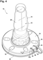
- FIG. 1 shows a protection device 10 attached to a handle 12 according to FIG figure 1 .
- the bag 14 of the protective device 10 completely encloses the grip area 20 of the handle 12 and thus completely closes it off.
- the mounting cup 16 of the guard 10 is attached to the base portion 22 of the handle 12 by engaging the threads 24 thereof with the threads 26 on the base portion 22 .
- the locking element 28 is fixed in the locking area or areas 30 of the base area 22 and can be released from this fixing by means of the unlocking device 32.
- FIG 5 shows a special embodiment of the mounting plate 16, wherein the bag 14 ( figure 1 ) is not shown.
- the special feature of this embodiment is that the unlocking device 32 in the direction of rotation of the mounting plate 16 when removing the Protection device 10 is aligned by a handle 12.
- the assembly plate 16 is already rotated in the direction necessary for removing the protective device 10 .
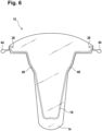
- FIG. 6 to Figure 12 show a further embodiment of a protective device 10 of the type proposed here for a handle 12 ( 7 ) of a medical device, which is also not shown here itself, for example a medical device in the form of an operating room light or a monitor recording.
- This protective device 10 also has a flexible part 14, referred to below as bag 14, and a fixed part 16, which is designed as a clip 16 in this embodiment.
- the clamp 16 is made of metal or a plastic, for example, and is in any case designed to be resilient or at least partially resilient.
- the bag 14 is firmly connected to the clamp 16 at least in partial areas 40, for example welded, glued or clamped.
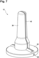
- the protection device 10 according to FIG figure 6 is for use with a handle 12 according to figure 7 intended.
- This has a guide 42 for the protective device 10 .
- the guide 42 begins in the grip area 20 of the handle 12, in particular at the free, upper end of the grip area 20, and extends to the base area 22 of the handle 12.
- the user removes the protective device 10 from a respective Sterile packaging and the bag 14 opens by gently squeezing the clip 16 together. This allows the protective device 10 to be pushed over the handle 12, with the bag 14 being pushed open further by the grip area 20 of the handle 12 if necessary.
- the bag 14 completely encloses the handle area 20 and thus completely covers it.
- the clamp 16 is guided by means of the guide 42 of the handle 12 and the bag 14 presses the clamp 16 into the guide 42 due to its own stress.
- the guide 42 has, for example, a round, V-shaped or angular profile.
- the clamp 16 can also be guided by means of a groove in the clamp 16 and a corresponding spring as a guide 42 on Handle 12 or a spring in the bracket 16 and a corresponding groove as a guide 42 on the handle 12 can be guaranteed.
- the clamp 16 locks with the base region 22 of the handle 12 by means of a locking element 28 comprised by the clamp 16.
- a locking element 28 comprised by the clamp 16.
- two locking hooks act as locking element 28, each of which engages in a locking area 30 at the foot of the handle 12, in particular in its base area 22.
- the locking hooks are disengaged from the locking area 30 by means of lateral auxiliary handles 44 and the protective device 10 can be pulled off the handle 12 .
- FIG figure 8 shows one on a handle 12 according to FIG figure 7 attached protection device 10 according to figure 6 .
- Inside the bag 14 you can see the clip 16 in the guide 42 on the handle 12 and the auxiliary grips 44 for releasing the latching of the clip 16 on the handle 12.
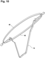
- FIG. 9 and figure 10 show a special embodiment of the protection device 10 according to FIG figure 6 .
- brackets 46 at the free ends of the clamp 16, of which in the representation of the folded protective device 10 in figure 9 only one is recognizable. This also makes it clear that the brackets 46 lie flat when the protective device 10 is in packaging (sterile packaging) and only stand up when the protective device 10 is attached to a handle 12 of a medical device.
- the bag 14 of such a protective device 10 is connected at least in sections with its edge on the open side to one of the brackets 46, for example by welding or gluing.
- Each bracket 46 is already arcuate in the relaxed state, with the arcuate shape specifying a preferred direction during later deformation when the protective device 10 is attached to a handle 12 .
- the bag 14 is opened by squeezing the legs of the clip 16. The force exerted on the ends of the two straps 46 as the legs of the clip 16 are compressed causes the ends of the two straps 46 to deform so that the straps 46 deform towards an arcuate shape of progressively smaller radius.
- the two brackets 46 When attached to the handle 12 , the two brackets 46 form a circular shape or approximately a circular shape or at least a shape that corresponds to the shape of the base area of the base area 22 of the handle 12 .
- the brackets 46 fix the edges of the bag 14 to the base area 22 of the handle 12, so that the handle 12 is covered as completely as possible, at least the handle area 20 is completely covered.
- the mobility of the brackets 46 includes folding out of the plane of the bracket 16 ( 9 ) into a plane perpendicular or at least substantially perpendicular to the plane of bracket 16 ( 10 ) and elastic flexibility.
- the mobility for folding out of the packaging position in the plane perpendicular or at least essentially perpendicular to the plane of the clamp 16 is ensured by means of suitable hinges, for example film hinges, at the connection points of the bracket 46 with the clamp 16.
- the flexibility of the brackets 46 is ensured by a suitable choice of material.
- the brackets 46 are made of a plastic, for example.
- the representation in figure 11 shows different positions for locking elements 28 arranged in pairs on a clamp 16 of the protective device 10.
- the handle 12 has corresponding locking areas 30 depending on the clamp variant.
- the locking elements 28 shown can also be combined individually or in pairs with other locking elements 28, for example in such a way that a clip 16 all in figure 11 shown locking elements 28 or individual in figure 11 shown locking elements 28 has.
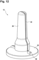
- the representation in figure 12 finally shows a variant of the handle 12, in which the locking area 30 is in the form of a hook on the handle 12 is embodied, for example in the form of a hook on the base area 22 of the handle 12.
- the protective device 10 is fixed to the handle 12 with such a locking area 30 by hooking the relevant section of the clip 16 into the hook.
- a protective device 10 acting as a protective cover for a part 12 of a medical device is specified, having a flexible part 14 and a fixed part 16, with the fixed part 16 having at least one locking element 28, which can be connected in a latching manner to a counterpart of the respective part 12 of the medical device, as well as a system which includes such a protective device 10 and a handle 12 of a medical device intended and set up for attaching such a protective device 10.
Landscapes
- Health & Medical Sciences (AREA)
- Surgery (AREA)
- Life Sciences & Earth Sciences (AREA)
- Heart & Thoracic Surgery (AREA)
- Molecular Biology (AREA)
- Veterinary Medicine (AREA)
- Engineering & Computer Science (AREA)
- Biomedical Technology (AREA)
- Public Health (AREA)
- Medical Informatics (AREA)
- General Health & Medical Sciences (AREA)
- Animal Behavior & Ethology (AREA)
- Pathology (AREA)
- Nuclear Medicine, Radiotherapy & Molecular Imaging (AREA)
- Oral & Maxillofacial Surgery (AREA)
- Infusion, Injection, And Reservoir Apparatuses (AREA)
- Surgical Instruments (AREA)
- Packages (AREA)
Description
- Die Erfindung betrifft eine als Schutzüberzug fungierende Vorrichtung (Schutzvorrichtung) für ein Teil eines Medizingeräts, insbesondere für einen Handgriff eines Medizingeräts, zum Beispiel eine zur Verwendung in einem Operationssaal bestimmte Leuchte (OP-Leuchte).
- Medizingeräte und damit auch zur Verwendung in einem Operationssaal bestimmte Medizingeräte müssen vom medizinischen Personal oftmals während der Verwendung, zum Beispiel während einer Operation, manuell verstellt oder justiert werden. Dafür besitzen solche Medizingeräte Handgriffe oder dergleichen, die steril sein müssen, um Übertragungsinfektionen durch einen Anwender auf einen Patienten oder umgekehrt zu verhindern. Üblicherweise werden zu diesem Zweck solche Handgriffe zum Beispiel vor jeder Operation gewechselt oder es wird eine Schutzvorrichtung in Form einer sterilen Abdeckung für den Einmalgebrauch oder in Form eines Einmalüberzugs auf dem Handgriff angebracht.
- Solche Einmalüberzüge bestehen zumeist aus einem Beutel aus einem Kunststoff, welcher über den jeweiligen Handgriff geschoben wird. Am offenen Ende wird der Beutel durch einen stabilen Anteil offen gehalten. Mittels des stabilen Anteils wird die Schutzvorrichtung oftmals kraft- oder formschlüssig mit dem Handgriff verbunden. Zusätzlich oder alternativ wird auch ein beim Aufsetzen einer Schutzvorrichtung auf den jeweiligen Handgriff resultierendes Vakuum zur Halterung an dem Handgriff genutzt, indem durch gute Abdichtung ein Luftzufluss in das Innere der Schutzvorrichtung verhindert wird.
- Bekannte Schutzvorrichtungen sind je nach Ausführung teuer in der Herstellung, insbesondere weil bereits die Einzelbauteile, speziell Einzelbauteile in Form von zum Beispiel tiefgezogenen Kunststoffteilen, teuer sind und mehrteilige Schutzvorrichtungen mittels aufwändiger Verfahren miteinander verbunden werden müssen.
- Gerade bei kraftschlüssigen Verbindungen zum jeweiligen Handgriff ist die Anbringung bekannter Schutzvorrichtungen an einem Medizingerät mitunter stark erschwert, da eine Anbringung mit nur einer Hand sehr aufwändig ist und teilweise muss daher eine weitere Person an nicht sterilen Bauteilen des Medizingerätes gegenhalten.
- Des Weiteren ist nach einer Benutzung bekannter Schutzvorrichtungen nicht ohne weiteres erkennbar, ob das jeweilige Produkt bereits montiert war. Bei Einmalprodukten besteht somit die latente Gefahr, durch fahrlässige oder mutwillige Mehrfachverwendung Patienten und Anwender zu infizieren.
- Schließlich haben bekannte Schutzvorrichtungen in einer jeweiligen Verpackung ein vergleichsweise großes Volumen. Dadurch steigen die Sterilisationskosten, die Kosten für die Sterilverpackung und der Platzbedarf für die Lagerung, wobei Letzteres aufgrund des ungleich stärker beschränkten Platzangebots besonders kritisch bei einer Lagerung im OP (Operationssaal) oder in einer Operationsabteilung ist.
- D1 (
US 5355292 ) zeigt eine Befestigungsvorrichtung (lighting fixture 10) für eine Beleuchtungseinrichtung (surgical lighting), welche ein Chirurg 16 verwenden kann. An einem Körper 12 ist eine Anordnung 14 mit einem Handgriff 18 und einem sterilen wegwerfbaren Überzug 20 angeordnet. Der Handgriff 18 hat einen Griffbereich (handle grip portion 26) und einen Basisbereich (central stud 24, adapter 22) mit einer umlaufenden starren Scheibe 36, einer weiteren starren Scheibe 38 und einer umlaufenden Aussparung 42. Der Überzug 20 umfasst einen elastischen Überzug 52 über den Griffbereich 26, einen starren umlaufenden Flansch (cover flange 58) und vier hakenförmige Vorsprünge 62, die in die Aussparung 42 eingreifen können. -
EP 3056164 A1 zeigt eine Schutzvorrichtung für eine Leuchte 10, welche einen Operationssaal beleuchten kann. Um Parameter der Leuchte 10 zu verändern, kann ein Benutzer einen Hebel (knob 42) drehen. Durch diese Drehung wird ein Basisteil 40 mit einer Plattform 52 gedreht. In das Basisteil 40 sind Betätigungselemente 114 eingelassen. Ein Überzug (cover 44) besitzt einen Teil 100 für den Hebel 42 und einen weiteren Teil 102 für die Plattform 52. Um den Überzug 44 zu befestigen, greift ein federbelasteter Hebel 406 in eine korrespondierende Aussparung 404 ein. - Zusammenfassung Anspruch 1 definiert die Erfindung und die abhängigen Ansprüche offenbaren Ausführungsformen. Eine Aufgabe der vorliegenden Erfindung besteht ausgehend von den oben skizzierten Beobachtungen bezüglich bekannter Schutzvorrichtungen darin, eine Schutzvorrichtung mit den Merkmalen des Oberbegriffs des Anspruchs 1 für einen Handgriff eines Medizingeräts anzugeben, die sich bezüglich einzelner oder mehrerer der genannten Nachteile durch Verbesserungen auszeichnet.
- Erfindungsgemäß wird diese Aufgabe mittels einer Schutzvorrichtung für einen Handgriff eines Medizingeräts mit den Merkmalen des Anspruchs 1 gelöst. Dazu ist bei einer Schutzvorrichtung für einen Handgriff eines Medizingeräts vorgesehen, dass die Schutzvorrichtung ein erstes, flexibles Teil und ein zweites, festes Teil umfasst, dass das flexible Teil bei einer am Handgriff angebrachten Schutzvorrichtung zumindest einen Griffbereich des Handgriffs vollständig abdeckt, dass das feste Teil lösbar mit einem Basisbereich des Handgriffs in Eingriff ist und dass das feste Teil zumindest ein Verriegelungselement zur lösbaren Fixierung am Basisbereich umfasst.
- Die hier vorgeschlagene Schutzvorrichtung für einen Handgriff eines Medizingeräts umfasst demnach ein festes, zur Fixierung der Schutzvorrichtung an dem Handgriff bestimmtes Teil sowie ein flexibles, zum Abdecken zumindest des Griffbereichs des Handgriffs bestimmtes, beutel- oder tütenartiges Teil, wobei beide Teile miteinander verbunden sind und wobei das feste Teil wenigstens ein Verriegelungselement aufweist, das mit einem Gegenstück des Handgriffs lösbar verbindbar, zum Beispiel rastend lösbar verbindbar ist. Typische Medizingeräte, an deren Handgriffen eine solche Schutzvorrichtung vorteilhaft verwendbar ist, sind zum Beispiel Operationsleuchten (OP-Leuchten) und Monitoraufnahmen.
- Ein Vorteil der Neuerung besteht darin, dass die Schutzvorrichtung leicht, insbesondere mit nur einer Hand, am jeweiligen Handgriff anbringbar und an diesem fixierbar ist, ohne dass dabei die Notwendigkeit besteht, die Umgebung des Handgriffs und das Medizingerät selbst und damit nicht sterile Teile berühren zu müssen. Darüber hinaus ergibt sich durch die Aufteilung in einen flexiblen Teil und einen festen Teil eine vorteilhaft kleine Packungsgröße, wobei im Wesentlichen der feste Teil das benötigte Volumen bestimmt.
- Lösungsgemäß weist die Schutzvorrichtung in ihrem festen Teil ein zum Zusammenwirken mit einem Gewinde oder einem Profil im Basisbereich des jeweiligen Handgriffs bestimmtes Gewinde oder Profil auf. Das Profil am festen Teil und das Profil am Basisteil sind in der Form oder nach Art eines Bajonettverschlusses ausgestaltet. Mittels eines solchen Gewindes oder Profils lässt sich eine besonders sichere Fixierung der Schutzvorrichtung am jeweiligen Handgriff gewährleisten.
- Vorteilhafte Ausgestaltungen der Erfindung sind Gegenstand der Unteransprüche. Dabei verwendete Rückbeziehungen weisen auf die weitere Ausbildung des Gegenstandes des Hauptanspruches durch die Merkmale des jeweiligen Unteranspruches hin. Sie sind nicht als ein Verzicht auf die Erzielung eines selbständigen, gegenständlichen Schutzes für die Merkmalskombinationen der rückbezogenen Unteransprüche zu verstehen. Des Weiteren ist im Hinblick auf eine Auslegung der Ansprüche sowie der Beschreibung bei einer näheren Konkretisierung eines Merkmals in einem nachgeordneten Anspruch davon auszugehen, dass eine derartige Beschränkung in den jeweils vorangehenden Ansprüchen sowie einer allgemeineren Ausführungsform der gegenständlichen Schutzvorrichtung nicht vorhanden ist. Jede Bezugnahme in der Beschreibung auf Aspekte nachgeordneter Ansprüche ist demnach auch ohne speziellen Hinweis ausdrücklich als Beschreibung optionaler Merkmale zu lesen.
- Bei einer Ausführungsform der Schutzvorrichtung weist diese Drehhilfen an ihrem festen Teil auf. Solche Drehhilfen erleichtern die zum Fixieren der Schutzvorrichtung am jeweiligen Handgriff notwendige Drehbewegung des festen Teils relativ zum Basisbereich des Handgriffs.
- Die Fixierung der Schutzvorrichtung an dem jeweiligen Handgriff lässt sich besonders leicht und unkompliziert aufheben, wenn die Schutzvorrichtung am festen Teil eine Entriegelungsvorrichtung zum Lösen des Verriegelungselements aus einer Fixierung im Basisbereich des Handgriffs aufweist.
- Bei einer besonderen Ausführungsform der Schutzvorrichtung weist diese am festen Teil zumindest eine der Entriegelungsvorrichtung räumlich zugeordnete Sollbruchstelle auf. Bei einer Betätigung der Entriegelungsvorrichtung, zum Beispiel einem mit der Hand des Anwenders ausgeübten Zug an der Entriegelungsvorrichtung, gibt die oder zumindest eine Sollbruchstelle nach, so dass eine irreversible Verformung des festen Teils der Schutzvorrichtung resultiert. Anhand einer solchen Verformung ist jederzeit sicher erkennbar, ob die Schutzvorrichtung bereits in Gebrauch war. Ein nicht vorgesehener Mehrfachgebrauch der Schutzvorrichtung kann damit wirksam verhindert werden.
- Eine besondere Ausführungsform der Schutzvorrichtung zeichnet sich durch ein starres, tellerförmiges festes Teil aus. Mit der Tellerform ist das feste Teil besonders gut an die übliche Form eines Basisbereichs eines Handgriffs an einem Medizingerät angepasst. Darüber hinaus lässt sich das tellerförmige feste Teil besonders gut am Basisbereich und damit die Schutzvorrichtung insgesamt besonders gut am Handgriff anbringen. Ein solches festes Teil wird im Weiteren demgemäß auch als Montageteller bezeichnet. Die Tellerform - also die runde Form - des festen Teils gewährleistet zudem eine allseitig gute Führung des flexiblen Teils durch das feste Teil, so dass das flexible Teil bei einer an einem Handgriff angebrachten Schutzvorrichtung allseitig gut am Griffbereich des Handgriffs anliegt.
- Bei einer alternativen Ausführungsform der Schutzvorrichtung umfasst diese eine zumindest in Teilbereichen mit dem flexiblen Teil verbundene Klammer als festes Teil. Eine solche Klammer ist im Rahmen ihrer Materialeigenschaften elastisch beweglich und ermöglicht beim Zusammendrücken zum Beispiel ein Öffnen des mit der Klammer verbundenen flexiblen Teils. Dies erleichtert die Anbringung der Schutzvorrichtung an dem jeweiligen Handgriff, nämlich das Überziehen des flexiblen Teils über den Griffbereich des Handgriffs. Zudem ist die Klammer ein flaches Bauteil und entsprechend ergibt sich für die Schutzvorrichtung im nicht benutzten Zustand eine vorteilhaft kleine Packungsgröße, wobei im Wesentlichen die Klammer die benötigte Grundfläche der Verpackung bestimmt.
- Bei einer Ausführungsform einer Schutzvorrichtung mit einer Klammer als festem Teil weist diese zur lösbaren Fixierung der Schutzvorrichtung an einem jeweiligen Handgriff an der Klammer zumindest einen als Verriegelungselement fungierenden Verriegelungshaken auf, der beim Fixieren an dem Handgriff in einen Verriegelungsbereich des Handgriffs eingreift.
- Bei einer weiteren besonderen Ausführungsform einer Schutzvorrichtung mit einer Klammer als festem Teil weist diese zwei an der Klammer angelenkte und mit dem flexiblen Teil in dessen Randbereich zumindest abschnittsweise verbundene Bügel auf. Diese Bügel öffnen den flexiblen Teil beim Zusammendrücken der Klammer in einer definierten Art und Weise und halten zudem das flexible Teil allseitig an dessen Rändern, so dass das flexible Teil bei einer an einem Handgriff angebrachten Schutzvorrichtung allseitig gut zumindest an dessen Griffbereich anliegt.
- Insgesamt ist die hier vorgeschlagene Neuerung auch ein System, welches einerseits eine Schutzvorrichtung der hier und im Folgenden beschriebenen Art und andererseits einen Handgriff eines Medizingeräts umfasst, wobei der Handgriff einen Griffbereich und einen Basisbereich aufweist. Bei einer besonderen Ausführungsform eines solchen Systems ist der Basisbereich des Handgriffs zur lösbaren Fixierung des festen Teils der Schutzvorrichtung am Handgriff eingerichtet und weist dafür zumindest einen Verriegelungsbereich zur Aufnahme des Verriegelungselements der Schutzvorrichtung auf. Bevorzugt ist wenigstens eine Sollbruchstelle vorgesehen, und derart ausgeführt, dass diese bei einem Entriegeln der Schutzvorrichtung bricht, so den bereits erfolgten Gebrauch der Schutzvorrichtung deutlich anzeigt und eine erneute Verwendung der Vorrichtung ausschließt.
- Bei einer weiteren Ausführungsform eines solchen Systems weist der Verriegelungsbereich einen Fügebereich, einen Rastbereich und dazwischen einen Anlaufbereich mit einer Anlaufschräge auf. Der Fügebereich ist beim Verbinden der Schutzvorrichtung mit dem Handgriff zur Aufnahme des Verriegelungselements der Schutzvorrichtung bestimmt und nimmt beim anfänglichen Verbinden der Schutzvorrichtung mit dem Handgriff das Verriegelungselement auf. Mittels der Anlaufschräge ist das Verriegelungselement der Schutzvorrichtung beim Verbinden der Schutzvorrichtung mit dem Handgriff und beim Drehen des festen Teils relativ zum Basisbereich des Handgriffs auslenkbar und wird beim Verbinden der Schutzvorrichtung mit dem Handgriff und beim Drehen des festen Teils relativ zum Basisbereich des Handgriffs ausgelenkt. Beim Weiterdrehen des festen Teils gelangt das Verriegelungselement von der Anlaufschräge in den Rastbereich und ist dort zur rastenden Fixierung des festen Teils am Basisbereich des Handgriffs wirksam.
- Nachfolgend werden Ausführungsbeispiele der Erfindung anhand von Zeichnungen näher erläutert. Einander entsprechende Gegenstände oder Elemente sind in allen Figuren mit den gleichen Bezugszeichen versehen.
- Das oder jedes Ausführungsbeispiel ist nicht als Einschränkung der Erfindung zu verstehen. Vielmehr sind im Rahmen der vorliegenden Offenbarung Abänderungen und Modifikationen möglich, insbesondere solche Varianten und Kombinationen, die zum Beispiel durch Kombination oder Abwandlung von einzelnen in Verbindung mit den im allgemeinen oder speziellen Beschreibungsteil beschriebenen sowie in den Ansprüchen und/oder der Zeichnung enthaltenen Merkmalen für den Fachmann im Hinblick auf die Lösung der Aufgabe entnehmbar sind und durch kombinierbare Merkmale zu einem neuen Gegenstand führen.
- Es zeigen:
- Figur 1
- eine Schutzvorrichtung für einen Handgriff eines Medizingeräts, gemäß der Erfindung,
- Figur 2
- einen für eine Anbringung einer Schutzvorrichtung gemäß
Figur 1 bestimmten Handgriff, - Figur 3
- einen Montageteller der Schutzvorrichtung gemäß
Figur 1 , - Figur 4
- eine an einem Handgriff angebrachte Schutzvorrichtung gemäß
Figur 1 , - Figur 5
- eine alternative Ausführungsform eines Montagetellers für eine Schutzvorrichtung gemäß
Figur 1 , - Figur 6
- eine weitere Schutzvorrichtung für einen Handgriff eines Medizingeräts, nicht erfindungsgemäß,
- Figur 7
- einen für eine Anbringung einer Schutzvorrichtung gemäß
Figur 6 bestimmten Handgriff, - Figur 8
- eine an einem Handgriff angebrachte Schutzvorrichtung gemäß
Figur 6 , - Figur 9
- eine spezielle Ausführungsform der Schutzvorrichtung gemäß
Figur 6 , - Figur 10
- ein Teil der Schutzvorrichtung gemäß
Figur 9 , - Figur 11
- spezielle Ausführungsformen eines Teils der Schutzvorrichtung gemäß
Figur 6 oderFigur 9 sowie - Figur 12
- eine alternative Ausführungsform eines für eine Anbringung einer Schutzvorrichtung gemäß
Figur 6 bestimmten Handgriffs. - Die Darstellung in
Figur 1 zeigt exemplarisch eine Ausführungsform der hier vorgeschlagenen Schutzvorrichtung 10 für einen Handgriff 12 (Fig. 2 ) eines selbst nicht gezeigten Medizingeräts, zum Beispiel eines Medizingeräts in Form einer OP-Leuchte oder einer Monitoraufnahme. Die Schutzvorrichtung 10 umfasst zwei miteinander verbundene Teile, nämlich ein erstes, flexibles Teil 14, welches über den Handgriff 12 gestülpt wird und im Folgenden kurz als Tüte 14 bezeichnet wird (genauso aber zum Beispiel auch als Beutel bezeichnet werden könnte), sowie ein zweites, festes (starres) Teil 16, mittels dessen die Schutzvorrichtung 10 an dem jeweiligen Handgriff 12 fixiert wird und das im Folgenden als Montageteller 16 bezeichnet wird. - Der Montageteller 16 und die Tüte 14 bestehen vorzugsweise aus einem Kunststoff. Die Tüte 14 ist mit dem Montageteller 16 fest verbunden. Die Verbindung kann zum Beispiel durch Verschweißen, Verkleben oder mittels eines geeigneten Zusatzbauteils durch Klemmen gegeben sein. Der Handgriff 12 weist einen Griffbereich 20 sowie einen Basisbereich 22 auf. Zumindest der Griffbereich 20 des Handgriffs 12 ist bei einer an dem Handgriff 12 angebrachten Schutzvorrichtung 10 komplett mittels der Tüte 14 der Schutzvorrichtung 10 abgedeckt. Die aus einer Sterilverpackung entnommene Schutzvorrichtung 10 wird dabei mit dem Handgriff 12 lösbar verbunden, indem die Tüte 14 über den Griffbereich 20 gestülpt und der Montageteller 16 lösbar am Basisbereich 22 angebracht wird.
- Am Montageteller 16 weist die Schutzvorrichtung 10 optionale Drehhilfen 18 auf, in oder an denen die Finger eines Anwenders Halt finden, um den Montageteller 16 der Schutzvorrichtung 10 bei der Anbringung an dem jeweiligen Medizingerät zu drehen. Diese Drehhilfen 18 können gegenüber der angrenzenden Oberfläche des Montagetellers 16 erhaben und/oder versenkt ausgeführt sein.
- Die Darstellung in
Figur 3 zeigt die Unterseite des Montagetellers 16. Mittels eines dabei erkennbaren, vom Montageteller 16 umfassten Profils oder Gewindes 24 ist die Schutzvorrichtung 10 formschlüssig mit dem Handgriff 12 des jeweiligen Medizingeräts verbindbar und wird beim Anbringen an einem Handgriff 12 formschlüssig mit diesem verbunden. Der Handgriff 12 oder das Medizingerät weisen dafür ein zum Profil oder Gewinde 24 der Schutzvorrichtung 10 korrespondierendes Profil oder Gewinde 26 (Fig. 2 ) auf. Bei dem Gewinde 24 im Montageteller 16 und dem Gewinde 26 am Basisbereich 22 des Handgriffs 12 muss es sich nicht notwendig um ein fortlaufend wendelartig umlaufendes Gewinde 24, 26 handeln. Tatsächlich reichen für eine formschlüssige Verbindung zueinander passende, kurze Schraubenlinienabschnitte aus, wie dies bei der dargestellten Ausführungsform der Fall ist. Alternativ kommt als Profil für eine formschlüssige Verbindung zum Beispiel ein Profil nach Art eines Bajonettverschlusses oder in Form eines Bajonettverschlusses in Betracht. Im Interesse einer besseren Lesbarkeit wird die hier vorgelegte Beschreibung am Beispiel eines Gewindes 24 (Innengewinde), insbesondere eines Innengewindes 24 in Form mehrerer kurzer Schraubenlinienabschnitte, auf der Seite des Montagetellers 16 und eines passenden Gewindes 26 auf der Seite des Handgriffs 12 oder des Medizingeräts fortgesetzt. Andere formschlüssige Verbindungsmöglichkeiten, insbesondere eine Verbindung in Form von oder nach Art eines Bajonettverschlusses, sind dabei stets mitzulesen und ausdrücklich als von der hier vorgelegten Beschreibung mit umfasst anzusehen. - Bei einer optionalen Ausführungsform umfasst der Montageteller 16 der Schutzvorrichtung 10 ein Verriegelungselement 28, das bei der gezeigten Ausführungsform in Form einer Verriegelungsfahne (
Fig. 3 ) realisiert ist. Das Verriegelungselement 28, insbesondere die Verriegelungsfahne, ist dazu bestimmt, die Schutzvorrichtung 10 in einer Endstellung der Drehbewegung auf dem Handgriff 12 zu verriegeln und damit eine ungewollte Demontage zu verhindern. Dazu greift das Verriegelungselement 28, insbesondere rastend, in einen dafür bestimmten Verriegelungsbereich 30 (Fig. 2 ) im Handgriff 12 ein, insbesondere in einen Verriegelungsbereich 30 in Form einer Ausnehmung im Gewinde 26 des Handgriffs 12. - Optional ist der Verriegelungsbereich 30 so ausgestaltet, dass mittels des Verriegelungsbereichs 30 das Verriegelungselement 28 des Montagetellers 16 beim Drehen des Montagetellers 16 bis in eine Endposition geführt und in dieser verriegelt wird. Dafür ist bei der gezeigten Ausführungsform der Verriegelungsbereich 30 entlang der Außenumfangsfläche des Basisbereichs 22 des Handgriffs 12 um ein Mehrfaches länger als die Breite der als Verriegelungselement 28 fungierenden Verriegelungsfahne. Konkret unterteilt sich der Verriegelungsbereich 30 in einen Fügebereich 30a, einen Anlaufbereich mit einer Anlaufschräge 30b und einen Rastbereich 30c.
- Der Fügebereich 30a und der Rastbereich 30c sind entlang der Außenumfangsfläche des Basisbereichs 22 des Handgriffs 12 geringfügig breiter als die Verriegelungsfahne, zumindest so breit, dass der Fügebereich 30a und der Rastbereich 30c die Verriegelungsfahne (Verriegelungselement 28) aufnehmen können.
- Beim Anbringen der Schutzvorrichtung 10 und beim Kombinieren von deren Montageteller 16 mit dem Basisbereich 22 des Handgriffs 12 ist oder wird der Montageteller 16 zunächst relativ zum Basisbereich 22 so orientiert, dass die Verriegelungsfahne in den Fügebereich 30a des Verriegelungsbereichs 30 gelangt. Nur dann kann der Montageteller 16 vollständig auf den Basisbereich 22 aufgesetzt werden, so dass das Gewinde 24 des Montagetellers 16 mit dem Gewinde 26 des Basisbereichs 22 zum Eingriff kommt. Beim anschließenden Drehen des Montagetellers 16 relativ zum Basisbereich 22 des Handgriffs 12 wird das Gewinde 24, 26 zunehmend fest und gleichzeitig gelangt die Verriegelungsfahne in den Anlaufbereich und gleitet entlang der Anlaufschräge 30b, wobei das freie Ende der Verriegelungsfahne im Rahmen von deren Materialelastizität radial nach außen ausgelenkt (unter reversibler Verformung nach außen gedrückt) wird. Beim fortgesetzten Weiterdrehen des Montagetellers 16 auf dem Basisbereich 22 gelangt die Verriegelungsfahne schließlich in den Rastbereich 30c. Dabei verlässt die Verriegelungsfahne die Anlaufschräge 30b und federt ohne die bisherige Auslenkung aufgrund der Anlaufschräge 30b in den Rastbereich 30c ein. Der Rastbereich 30c ist in Richtung der bisherigen Drehung durch das Ende des Verriegelungsbereichs 30 und in Gegenrichtung durch das Ende der Anlaufschräge 30b begrenzt. Dieses Ende der Anlaufschräge 30b ist nicht angeschrägt, so dass die in den Rastbereich 30c eingerastete Verriegelungsfahne das Weiterdrehen des Montagetellers 16, aber auch ein Zurückdrehen des Montagetellers 16 verhindert. Der Montageteller 16 ist damit in einer durch den Verriegelungsbereich 30 definierten Endposition am Handgriff 12, nämlich an dessen Basisbereich 22, fixiert, wodurch insgesamt die Schutzvorrichtung 10 am Handgriff 12 fixiert ist.
- Optional ist der Verriegelungsbereich 30 mehrfach auf dem Umfang des Basisbereichs 22 vorhanden, insbesondere in einer das Gewinde 24 unterbrechenden Art und Weise. Bei der gezeigten Ausführungsform weist der Basisbereich 22 des Handgriffs 12 mehrere äquidistante Verriegelungsbereiche 30 auf, nämlich drei Verriegelungsbereiche 30, und mit den drei Verriegelungsbereichen 30 wechseln sich entlang des Außenumfangs des Basisbereichs 22 drei Bereiche mit jeweils einem Abschnitt des Gewindes 26 ab.
- Bei einer speziellen Variante dieser Ausführungsform dient das Verriegelungselement 28 als fester Anschlag, um bei der durch "Aufschrauben" des Montagetellers 16 auf den Basisbereich 22 erfolgenden Anbringung der Schutzvorrichtung 10 an dem Handgriff 12 eine eindeutige Endstellung des Montagetellers 16 relativ zum Basisbereich 22 zu definieren.
- Zum Entriegeln einer an einem Handgriff 12 fixierten Schutzvorrichtung 10 ist an der Schutzvorrichtung 10 eine Entriegelungsvorrichtung 32 vorgesehen, die zur leichteren Handhabung zum Beispiel einen Griffring an deren Ende aufweisen kann. Mittels der Entriegelungsvorrichtung 32 wird das Verriegelungselement 28 außer Eingriff mit dem Verriegelungsbereich 30 gebracht. Ohne das im Verriegelungsbereich 30 fixierte, insbesondere eingerastete Verriegelungselement 28 zu betätigen, kann der Montageteller 16 auch nicht mittels einer Drehbewegung vom Handgriff 12 gelöst und damit die Schutzvorrichtung 10 insgesamt nicht vom Handgriff 12 entfernt werden.
- Bei einer besonderen Ausführungsform wird bei der Entriegelung ein Bereich um die Entriegelungsvorrichtung 32 irreversibel deformiert, zum Beispiel eingerissen. Dies wird durch eine geeignete Ausführung des Montagetellers 16 in diesem Bereich unterstützt, zum Beispiel in Form zumindest einer Sollbruchstelle 34a in diesem Bereich, insbesondere einer Sollbruchstelle 34 in Form einer Kerbe oder einer sonstigen Materialschwächung. Bei der gezeigten Ausführungsform schließt die Sollbruchstelle 34a an zumindest einen Schlitz 34 im Montageteller 16 an, nämlich an einen Schlitz 34 oder zwei parallele oder im Wesentlichen parallele Schlitze 34, der bzw. die eine Beweglichkeit der Entriegelungsvorrichtung 32 ermöglicht bzw. ermöglichen. Beim Aufbrechen der Sollbruchstelle 34 ist der Montageteller 16 nach der Entriegelung mittels der Entriegelungsvorrichtung 32 irreversibel deformiert. Der Anwender kann damit die Schutzvorrichtung 10 als "bereits benutzt" erkennen. Somit wird eine Wiederverwendung der als Einmalprodukt vorgesehenen Schutzvorrichtung 10 wirkungsvoll verhindert werden.
- Die Darstellung in
Figur 4 zeigt eine an einem Handgriff 12 angebrachte Schutzvorrichtung 10 gemäßFigur 1 . Die Tüte 14 der Schutzvorrichtung 10 schließt den Griffbereich 20 des Handgriffs 12 vollständig ein und schließt diesen damit vollständig ab. Der Montageteller 16 der Schutzvorrichtung 10 ist am Basisbereich 22 des Handgriffs 12 angebracht, indem sich dessen Gewinde 24 mit dem Gewinde 26 am Basisbereich 22 in Eingriff befindet. Bei einer Schutzvorrichtung 10 mit einem Verriegelungselement 28 und einer Entriegelungsvorrichtung 32 ist das Verriegelungselement 28 bei einer bestimmungsgemäß am Handgriff 12 angebrachten Schutzvorrichtung 10 in dem oder einem Verriegelungsbereich 30 des Basisbereichs 22 fixiert und mittels der Entriegelungsvorrichtung 32 aus dieser Fixierung lösbar. - Die Darstellung in
Figur 5 zeigt eine spezielle Ausführungsform des Montagetellers 16, wobei die bei einer kompletten Schutzvorrichtung 10 am Montageteller 16 angebrachte Tüte 14 (Figur 1 ) nicht gezeigt ist. Die Besonderheit dieser Ausführungsform besteht darin, dass die Entriegelungsvorrichtung 32 in Richtung der Drehbewegung des Montagetellers 16 beim Entfernen der Schutzvorrichtung 10 von einem Handgriff 12 ausgerichtet ist. Somit wird nach der Entriegelung mittels der Entriegelungsvorrichtung 32 der Montageteller 16 bereits in die für das Abnehmen der Schutzvorrichtung 10 notwendige Richtung gedreht. - Die Darstellungen in
Figur 6 bis Figur 12 zeigen eine weitere Ausführungsform einer Schutzvorrichtung 10 der hier vorgeschlagenen Art für einen Handgriff 12 (Fig. 7 ) eines auch hier selbst nicht dargestellten Medizingeräts, zum Beispiel eines Medizingeräts in Form einer OP-Leuchte oder einer Monitoraufnahme. Auch diese Schutzvorrichtung 10 weist einen im Folgenden als Tüte 14 bezeichneten flexiblen Teil 14 sowie einen festen Teil 16 auf, der bei dieser Ausführungsform als Klammer 16 ausgeführt ist. Die Klammer 16 ist zum Beispiel aus Metall oder einem Kunststoff gefertigt und jedenfalls federnd elastisch oder zumindest abschnittsweise federnd elastisch ausgeführt. Die Tüte 14 ist zumindest in Teilbereichen 40 fest mit der Klammer 16 verbunden, zum Beispiel verschweißt, verklebt oder verklemmt. - Die Schutzvorrichtung 10 gemäß
Figur 6 ist zur Verwendung mit einem Handgriff 12 gemäßFigur 7 vorgesehen. Dieser weist eine Führung 42 für die Schutzvorrichtung 10 auf. Die Führung 42 beginnt im Griffbereich 20 des Handgriffs 12, insbesondere am freien, oberen Ende des Griffbereichs 20, und reicht bis zum Basisbereich 22 des Handgriffs 12. Zum Anbringen der Schutzvorrichtung 10 an einem solchen Handgriff 12 entnimmt der Anwender die Schutzvorrichtung 10 aus einer jeweiligen Sterilverpackung und durch leichtes Zusammendrücken der Klammer 16 öffnet sich die Tüte 14. Damit lässt sich die Schutzvorrichtung 10 über den Handgriff 12 schieben, wobei die Tüte 14 durch den Griffbereich 20 des Handgriffs 12 gegebenenfalls weiter aufgedrückt wird. Bei einer bestimmungsgemäß am Handgriff 12 angebrachten Schutzvorrichtung 10 schließt die Tüte 14 den Griffbereich 20 vollständig ein und deckt diesen damit vollständig ab. Die Klammer 16 wird dabei mittels der Führung 42 des Handgriffs 12 geführt und die Tüte 14 drückt durch die Eigenspannung die Klammer 16 in die Führung 42. Die Führung 42 weist zum Beispiel ein rundes, V-förmiges oder eckiges Profil auf. Alternativ kann eine Führung der Klammer 16 auch mittels einer Nut in der Klammer 16 und einer korrespondierenden Feder als Führung 42 am Handgriff 12 oder einer Feder in der Klammer 16 und einer korrespondierenden Nut als Führung 42 am Handgriff 12 gewährleistet sein. - In der Endposition verriegelt sich die Klammer 16 mit dem Basisbereich 22 des Handgriffs 12 mittels eines von der Klammer 16 umfassten Verriegelungselements 28. Bei der Ausführungsform gemäß
Figur 6 fungieren als Verriegelungselement 28 zwei Verriegelungshaken, die in jeweils einen Verriegelungsbereich 30 am Fuß des Handgriffs 12, insbesondere in dessen Basisbereich 22, eingreifen. Zum Abnehmen der Schutzvorrichtung 10 von einem Handgriff 12 nach Ende der Verwendung werden die Verriegelungshaken mittels seitlicher Hilfsgriffe 44 außer Eingriff mit dem Verriegelungsbereich 30 gebracht und die Schutzvorrichtung 10 kann vom Handgriff 12 abgezogen werden. - Die Darstellung in
Figur 8 zeigt eine an einem Handgriff 12 gemäßFigur 7 angebrachte Schutzvorrichtung 10 gemäßFigur 6 . Man erkennt im Innern der Tüte 14 die Klammer 16 in der Führung 42 am Handgriff 12 sowie die Hilfsgriffe 44 zum Lösen der Verrastung der Klammer 16 am Handgriff 12. - Die Darstellungen in
Figur 9 undFigur 10 zeigen eine spezielle Ausführungsform der Schutzvorrichtung 10 gemäßFigur 6 . Hier befinden sich an den freien Enden der Klammer 16 zwei Bügel 46, von denen bei der Darstellung der zusammengelegten Schutzvorrichtung 10 inFigur 9 nur einer erkennbar ist. Dadurch wird auch deutlich, dass die Bügel 46 bei einer sich in einer Verpackung (Sterilverpackung) befindlichen Schutzvorrichtung 10 flach liegen und sich erst beim Anbringen der Schutzvorrichtung 10 an einem Handgriff 12 eines Medizingeräts aufstellen. - Die Tüte 14 einer solchen Schutzvorrichtung 10 ist mit ihrem Rand an der offenen Seite zumindest abschnittsweise mit jeweils einem der Bügel 46 verbunden, zum Beispiel durch Verschweißen oder Verkleben. Jeder Bügel 46 ist bereits im entspannten Zustand bogenförmig, wobei die Bogenform eine Vorzugsrichtung beim späteren Verformen beim Anbringen der Schutzvorrichtung 10 an einem Handgriff 12 vorgibt. Beim Anbringen der Schutzvorrichtung 10 an einem Handgriff 12 wird wie bei der Ausführungsform gemäß
Figur 6 die Tüte 14 durch Zusammendrücken der Schenkel der Klammer 16 geöffnet. Die beim Zusammendrücken der Schenkel der Klammer 16 auf die Enden der beiden Bügel 46 ausgeübte Kraft bewirkt deren Verformung, so dass sich die Bügel 46 in Richtung auf eine Bogenform mit einem zunehmend kleineren Radius verformen. Im an dem Handgriff 12 angebrachten Zustand bilden die beiden Bügel 46 eine Kreisform oder näherungsweise eine Kreisform oder zumindest eine Form, die der Form der Grundfläche des Basisbereichs 22 des Handgriffs 12 entspricht. Die Bügel 46 fixieren die Ränder der Tüte 14 am Basisbereich 22 des Handgriffs 12, so dass eine möglichst vollständige Abdeckung des Handgriffs 12 gewährleistet ist, zumindest eine vollständige Abdeckung von dessen Griffbereich 20. - Die Beweglichkeit der Bügel 46 umfasst ein Umklappen aus der Ebene der Klammer 16 (
Fig. 9 ) in eine Ebene senkrecht oder zumindest im Wesentlichen senkrecht zu der Ebene der Klammer 16 (Fig. 10 ) sowie eine elastische Biegsamkeit. Die Beweglichkeit zum Umklappen aus der Verpackungsposition in die Ebene senkrecht oder zumindest im Wesentlichen senkrecht zu der Ebene der Klammer 16 wird mittels geeigneter Scharniere, zum Beispiel Filmscharniere, an den Verbindungsstellen der Bügel 46 mit der Klammer 16 gewährleistet. Die Biegsamkeit der Bügel 46 wird mittels einer geeigneten Materialauswahl gewährleistet. Die Bügel 46 sind zum Beispiel aus einem Kunststoff gefertigt. - Die Darstellung in
Figur 11 zeigt unterschiedliche Positionen für jeweils paarweise angeordnete Verriegelungselemente 28 an einer Klammer 16 der Schutzvorrichtung 10. Der Handgriff 12 weist je nach Klammervariante entsprechende Verriegelungsbereiche 30 auf. Die inFigur 11 gezeigten Verriegelungselemente 28 können einzeln oder paarweise auch mit weiteren Verriegelungselementen 28 kombiniert werden, zum Beispiel derart, dass eine Klammer 16 alle inFigur 11 gezeigten Verriegelungselemente 28 oder einzelne inFigur 11 gezeigte Verriegelungselemente 28 aufweist. - Die Darstellung in
Figur 12 zeigt abschließend eine Variante des Handgriffs 12, bei welcher der Verriegelungsbereich 30 in Form eines Hakens am Handgriff 12 ausgeführt ist, zum Beispiel in Form eines Hakens am Basisbereich 22 des Handgriffs 12. Die Schutzvorrichtung 10 wird bei einem solchen Verriegelungsbereich 30 am Handgriff 12 fixiert, indem der betreffende Abschnitt der Klammer 16 in den Haken eingehakt wird. - Einzelne im Vordergrund stehende Aspekte der hier eingereichten Beschreibung lassen sich damit kurz wie folgt zusammenfassen: Angegeben werden eine als Schutzüberzug für ein Teil 12 eines Medizingeräts fungierende Schutzvorrichtung 10 mit einem flexiblen Teil 14 und einem festen Teil 16, wobei das feste Teil 16 wenigstens ein Verriegelungselement 28 aufweist, das mit einem Gegenstück des jeweiligen Teils 12 des Medizingeräts rastend verbindbar ist, sowie ein System, welches eine solche Schutzvorrichtung 10 und einen zum Anbringen einer solchen Schutzvorrichtung 10 bestimmten und eingerichteten Handgriff 12 eines Medizingeräts umfasst.
-
- 10
- Schutzvorrichtung
- 12
- Handgriff
- 14
- flexibles Teil der Schutzvorrichtung / Tüte
- 16
- festes Teil der Schutzvorrichtung / Montageteller oder Klammer
- 18
- Drehhilfe
- 20
- Griffbereich
- 22
- Basisbereich
- 24
- Gewinde
- 26
- Gewinde
- 28
- Verriegelungselement
- 30
- Verriegelungsbereich
- 30a
- Fügebereich
- 30b
- Anlaufschräge
- 30c
- Rastbereich
- 32
- Entriegelungsvorrichtung
- 34
- Schlitz
- 34a
- Sollbruchstelle
- 36-38
- (frei)
- 40
- Teilbereich (der Klammer)
- 42
- Führung
- 44
- Hilfsgriff
- 46
- Bügel
Claims (12)
- Schutzvorrichtung (10) für einen Handgriff (12) eines Medizingeräts,wobei die Schutzvorrichtung (10) ein erstes, flexibles Teil (14) und ein zweites, festes Teil (16) umfasst,wobei das flexible Teil (14) bei einer am Handgriff (12) angebrachten Schutzvorrichtung (10) zumindest einen Griffbereich (20) des Handgriffs (12) vollständig abdeckt undwobei das feste Teil (16) lösbar mit einem Basisbereich (22) des Handgriffs (12) in Eingriff ist,dadurch gekennzeichnet, dassdas feste Teil (16) zumindest ein Verriegelungselement (28) zur lösbaren Fixierung am Basisbereich (22) umfasst,ein Profil in Form oder nach Art eines Bajonettverschlusses oder ein Gewinde (24) im festen Teil (16) vorgesehen ist,welches zum Zusammenwirken mit einem Profil in Form oder nach Art eines Bajonettverschlusses oder einem Gewinde (26) im Basisbereich (22) bestimmt ist,wobei das feste Teil (12) der Schutzvorrichtung (10) relativ zum Basisbereich (22) des Handgriffs (12) drehbar ist undwobei das Verriegelungselement (28) die Form einer Verriegelungsfahne aufweist, die dazu ausgestaltet ist, in einen Verriegelungsbereich (30) im Handgriff (12) einzugreifen.
- Schutzvorrichtung (10) nach Anspruch 1, dadurch gekennzeichnet, dass das Verriegelungselement (28) die Schutzvorrichtung (10) in einer Endstellung der Drehbewegung auf dem Handgriff (12) zu verriegeln vermag.
- Schutzvorrichtung (10) nach Anspruch 1 oder 2, mit Drehhilfen (18) am festen Teil (16).
- Schutzvorrichtung (10) nach Anspruch 1, 2 oder 3, mit einer zum Lösen des Verriegelungselements (28) aus einer Fixierung im Basisbereich (22) des Handgriffs (12) bestimmten Entriegelungsvorrichtung (32) am festen Teil (16).
- Schutzvorrichtung (10) nach Anspruch 4, mit zumindest einer der Entriegelungsvorrichtung (32) am festen Teil (16) räumlich zugeordneten Sollbruchstelle (34a).
- Schutzvorrichtung (10) nach einem der Ansprüche 1 bis 5, mit einem starren, tellerförmigen festen Teil (16).
- Schutzvorrichtung (10) nach Anspruch 1, mit einer zumindest in Teilbereichen (40) mit dem flexiblen Teil (14) verbundenen Klammer (16) als festem Teil (16).
- Schutzvorrichtung (10) nach Anspruch 7, mit zumindest einem als Verriegelungselement (28) fungierenden Verriegelungshaken an der Klammer (16).
- Schutzvorrichtung (10) nach Anspruch 7 oder 8, mit zwei an der Klammer (16) angelenkten und mit dem flexiblen Teil (14) in dessen Randbereich zumindest abschnittsweise verbundenen Bügeln (46).
- Handgriff für ein Medizingerät mit einer Schutzvorrichtung nach einem der Ansprüche 1 bis 9.
- System mit einer Schutzvorrichtung (10) nach einem der Ansprüche 1 bis 9 und einem Handgriff (12) eines Medizingeräts,wobei der Handgriff (12) einen Griffbereich (20) und einen Basisbereich (22) aufweist undwobei der Basisbereich (22) zur lösbaren Fixierung des festen Teils (16) der Schutzvorrichtung (10) am Handgriff (12) eingerichtet ist, indem der Basisbereich (22) zumindest einen Verriegelungsbereich (30) zur Aufnahme des Verriegelungselements (28) der Schutzvorrichtung (10) aufweist.
- System nach Anspruch 11, wobei der Verriegelungsbereich (30) einen Fügebereich (30a), einen Rastbereich (30c) und dazwischen einen Anlaufbereich mit einer Anlaufschräge (30b) aufweist,wobei beim Verbinden der Schutzvorrichtung (10) mit dem Handgriff (12) zunächst der Fügebereich (30a) das Verriegelungselement (28) aufnimmt,wobei beim Verbinden der Schutzvorrichtung (10) mit dem Handgriff (12) und beim Drehen des festen Teils (16) relativ zum Basisbereich (22) des Handgriffs (12) die Anlaufschräge (30b) das Verriegelungselement (28) auslenkt undwobei beim Weiterdrehen des festen Teils (16) das Verriegelungselement (28) von der Anlaufschräge (30b) in den Rastbereich (30c) gelangt und dort zur rastenden Fixierung des festen Teils (16) am Basisbereich (22) des Handgriffs (12) wirksam ist.
Applications Claiming Priority (2)
| Application Number | Priority Date | Filing Date | Title |
|---|---|---|---|
| DE102016013394.5A DE102016013394A1 (de) | 2016-11-11 | 2016-11-11 | Schutzüberzug für ein Teil eines Medizingeräts |
| PCT/EP2017/001296 WO2018086736A1 (de) | 2016-11-11 | 2017-11-08 | Schutzüberzug für ein teil eines medizingeräts |
Publications (2)
| Publication Number | Publication Date |
|---|---|
| EP3538014A1 EP3538014A1 (de) | 2019-09-18 |
| EP3538014B1 true EP3538014B1 (de) | 2023-06-28 |
Family
ID=60972163
Family Applications (1)
| Application Number | Title | Priority Date | Filing Date |
|---|---|---|---|
| EP17829123.3A Active EP3538014B1 (de) | 2016-11-11 | 2017-11-08 | Schutzüberzug für ein teil eines medizingeräts |
Country Status (5)
| Country | Link |
|---|---|
| US (2) | US11317984B2 (de) |
| EP (1) | EP3538014B1 (de) |
| CN (2) | CN114404061A (de) |
| DE (1) | DE102016013394A1 (de) |
| WO (1) | WO2018086736A1 (de) |
Families Citing this family (3)
| Publication number | Priority date | Publication date | Assignee | Title |
|---|---|---|---|---|
| DE202019105921U1 (de) * | 2019-10-24 | 2019-11-06 | Ulrich Bahr | Befestigungsvorrichtung zur Befestigung eines Abdeckmittels an einem Arbeits- oder Untersuchungsgerät |
| EP4518788A1 (de) * | 2022-05-04 | 2025-03-12 | American Sterilizer Company | Sterilisierbare abdeckung für den griff eines zubehörteils einer medizinischen hängedeckenanordnung |
| CN114680882A (zh) * | 2022-06-01 | 2022-07-01 | 苏州百孝医疗科技有限公司 | 分析物浓度监测系统及使用方法 |
Citations (2)
| Publication number | Priority date | Publication date | Assignee | Title |
|---|---|---|---|---|
| US20030014834A1 (en) * | 2001-07-19 | 2003-01-23 | Naughton Michael L. | Laser light handle |
| US20140226304A1 (en) * | 2013-02-11 | 2014-08-14 | Palmetto Biomedical Inc. | Adjustable surgical light device and system |
Family Cites Families (40)
| Publication number | Priority date | Publication date | Assignee | Title |
|---|---|---|---|---|
| US4605124A (en) * | 1983-08-09 | 1986-08-12 | Devon Industries, Inc. | Disposable cover for surgical light handle |
| US4559671A (en) * | 1984-05-02 | 1985-12-24 | Medical Research Associates Ltd. #2 | Sterile handle cover for surgical lamp |
| EP0402412A4 (en) * | 1988-03-04 | 1991-08-28 | Mdt Corporation | Handle for surgery lamp |
| US4844252B1 (en) * | 1988-07-27 | 1993-03-16 | Multi-part disposable handle for hospital surgery room light fixture | |
| WO1990002292A1 (en) * | 1988-08-24 | 1990-03-08 | Transmedical Corporation | Lamp handle cover system for surgical lamps |
| US4976299A (en) * | 1989-06-27 | 1990-12-11 | Bickelman Harry M | Sterile disposable cover for a cylindrical handle |
| US4974288A (en) * | 1990-01-23 | 1990-12-04 | Timm Reasner | Disposable protective handle and shield for surgical luminaire |
| US5065296A (en) * | 1991-03-20 | 1991-11-12 | Deroyal Industries, Inc. | Handle and cover for positionable lighting fixture |
| US5156456A (en) | 1992-02-28 | 1992-10-20 | American Medical Manufacturing, Inc. | Replacement handle and disposable cover combination for surgery room light fixtures |
| US5355292A (en) * | 1992-02-28 | 1994-10-11 | American Medical Manufacturing Inc. | Surgical light cover and light handle adapter |
| US5469600A (en) | 1992-06-23 | 1995-11-28 | Devon Industries, Inc. | Disposable cover for contoured surgical light handle |
| US5408400A (en) | 1993-10-12 | 1995-04-18 | Gordon; Chester D. | Disposable sterile covering for dental and surgical lighting fixtures |
| US5700085A (en) | 1995-01-05 | 1997-12-23 | Calderwood; Mitchell C. | Surgical or clinical lamp handle shield or prophylactic |
| US5735598A (en) | 1995-06-19 | 1998-04-07 | Graphic Controls Corporation | Surgical light handle cover |
| US5709465A (en) | 1995-12-07 | 1998-01-20 | Getinge/Castle, Inc. | Disposable surgical light handle cover |
| US5884996A (en) * | 1996-07-11 | 1999-03-23 | Cottone; Anthony J. | Sterile handle covers |
| US6402351B1 (en) | 1998-03-27 | 2002-06-11 | Hill-Rom Services, Inc., | Controls for a surgical light apparatus |
| US6370735B1 (en) | 2000-01-05 | 2002-04-16 | Robert T. Horan | Surgical light handle |
| DE10000701A1 (de) * | 2000-01-10 | 2001-07-12 | Bosch Gmbh Robert | Winkelschleiferschutzhaube |
| US6447149B1 (en) | 2001-04-12 | 2002-09-10 | Xodus Medical, Inc. | Surgical light handle cover |
| CN1643298A (zh) | 2002-02-25 | 2005-07-20 | 斯特里斯公司 | 外科照明系统中的人体工程控制器 |
| US6692141B2 (en) | 2002-02-25 | 2004-02-17 | Steris Inc. | Disposable sterile cover for surgical lamps |
| ZA200602787B (en) * | 2003-10-20 | 2007-07-25 | Tokue Inc | Boot for universal shift coupling |
| IL160468A0 (en) | 2004-02-19 | 2004-07-25 | Assaf Halamish | Sterile handle cover for surgical lamp |
| DE202005007594U1 (de) * | 2005-05-13 | 2006-09-21 | Andreas Stihl Ag & Co. Kg | Gehäusedeckelanordnung |
| DE102008061362A1 (de) * | 2008-12-10 | 2010-06-17 | Berchtold Holding Gmbh | Hülse |
| US8752987B1 (en) * | 2011-01-05 | 2014-06-17 | Moshe Mike Hoftman | Vacuum secured lightweight surgical light handle cover |
| CN103104628B (zh) * | 2011-11-09 | 2015-12-16 | 现代威亚株式会社 | 用于车辆的成角度偏移球笼式等速万向节 |
| CN103185185B (zh) * | 2011-12-27 | 2015-04-29 | 上海宝钢设备检修有限公司 | 液压软管的防护罩 |
| US8763207B2 (en) | 2012-09-13 | 2014-07-01 | Aspen Surgical Products, Inc. | Method for making a light handle cover |
| US8789243B2 (en) | 2012-09-19 | 2014-07-29 | Ecolab Usa Inc. | Disposable handle cover for a surgical lighthead |
| DE102013017140B4 (de) * | 2013-10-16 | 2019-05-02 | Rose Plastic Ag | Flexible Schutzkappe zur Aufnahme von Schäften mit unterschiedlichem Durchmesser |
| WO2015158397A1 (en) * | 2014-04-17 | 2015-10-22 | Arcroyal Research | A disposable light handle cover and applicator |
| AU2015262928A1 (en) * | 2014-05-21 | 2017-01-12 | D.M. Benatav Ltd. | Universal handle cover |
| DE102014222880A1 (de) | 2014-11-10 | 2016-05-12 | Xion Gmbh | Adapter für die Endoskopie |
| CN104590787B (zh) * | 2015-01-14 | 2017-06-13 | 上海鸿研物流技术有限公司 | 容器及其锁定机构 |
| US10439611B2 (en) * | 2015-02-11 | 2019-10-08 | Stryker Corporation | Sterile handle control mechanism |
| CN204618410U (zh) | 2015-04-02 | 2015-09-09 | 稳健医疗用品股份有限公司 | 一次性医用手术灯柄罩 |
| CN104891322B (zh) * | 2015-06-11 | 2016-07-27 | 衢州市依科达节能技术有限公司 | 一种酸碱防护吊装罩 |
| US10531931B1 (en) * | 2016-04-01 | 2020-01-14 | Moshe Hoftman | Combination flexible and semi-rigid light handle cover |
-
2016
- 2016-11-11 DE DE102016013394.5A patent/DE102016013394A1/de not_active Withdrawn
-
2017
- 2017-11-08 WO PCT/EP2017/001296 patent/WO2018086736A1/de not_active Ceased
- 2017-11-08 CN CN202210106882.4A patent/CN114404061A/zh active Pending
- 2017-11-08 CN CN201780069893.7A patent/CN109952072B/zh active Active
- 2017-11-08 US US16/349,010 patent/US11317984B2/en active Active
- 2017-11-08 EP EP17829123.3A patent/EP3538014B1/de active Active
-
2022
- 2022-03-25 US US17/704,720 patent/US12213759B2/en active Active
Patent Citations (2)
| Publication number | Priority date | Publication date | Assignee | Title |
|---|---|---|---|---|
| US20030014834A1 (en) * | 2001-07-19 | 2003-01-23 | Naughton Michael L. | Laser light handle |
| US20140226304A1 (en) * | 2013-02-11 | 2014-08-14 | Palmetto Biomedical Inc. | Adjustable surgical light device and system |
Also Published As
| Publication number | Publication date |
|---|---|
| US20220211457A1 (en) | 2022-07-07 |
| CN109952072B (zh) | 2022-02-18 |
| US12213759B2 (en) | 2025-02-04 |
| EP3538014A1 (de) | 2019-09-18 |
| WO2018086736A1 (de) | 2018-05-17 |
| CN109952072A (zh) | 2019-06-28 |
| CN114404061A (zh) | 2022-04-29 |
| US11317984B2 (en) | 2022-05-03 |
| DE102016013394A1 (de) | 2018-05-17 |
| US20190262091A1 (en) | 2019-08-29 |
Similar Documents
| Publication | Publication Date | Title |
|---|---|---|
| EP2934359B1 (de) | Instrumentenhalter | |
| DE102015004952B4 (de) | Griff sowie Außenteil eines Griffs für ein Medizingerät | |
| DE2841119B2 (de) | Wegwerfbehälter zur Aufnahme von benutzten Skalpellklingen | |
| EP1117329A2 (de) | Vorrichtung zur perforation von haut | |
| DE19755532A1 (de) | Sterilcontainer für medizinische Zwecke | |
| EP1976576A2 (de) | Befestigungsvorrichtung für drainagebehälter | |
| DE69015047T2 (de) | Spuckbecher. | |
| DE102010016332A1 (de) | Chirurgisches Gerät | |
| WO2018086736A1 (de) | Schutzüberzug für ein teil eines medizingeräts | |
| DE102007009340A1 (de) | Nadelschutzvorrichtung mit integrierter Nadelträgerentfernungsvorrichtung zum Entfernen eines Nadelträgers von einem Injektionsgerät | |
| EP1109471A1 (de) | Manikürkapsel | |
| EP2916764B1 (de) | Instrumentenhalter zum befestigen eines medizinischen instrumentes an einem gelenkarm | |
| EP3175754A1 (de) | Entnahmesystem für tuchspender | |
| EP1480686B1 (de) | Sterilbehälter und filtereinheit für einen sterilbehälter | |
| EP2395926B1 (de) | Chirurgische klammereinrichtung | |
| DE3903974C2 (de) | ||
| DE102005047188B4 (de) | Chirurgische Halterung, dazugehörigen Satz und chirurgischer Behälter mit einer solchen Halterung | |
| DE102013111859B3 (de) | Feuchttuchspendersystem | |
| DE19845817C2 (de) | Fadenfixierclip | |
| DE202005015459U1 (de) | Chirurgische Halterung | |
| EP3999142A1 (de) | Schutzvorrichtung für das nadelrohr einer spritze | |
| DE29711829U1 (de) | Schnellspannklammer für eine Wundspreizvorrichtung | |
| DE1566159C3 (de) | Aufbewahrungsvorrichtung für steriles chirurgisches Nahtmaterial | |
| DE20213523U1 (de) | Sterilbehälter und Filtereinheit für einen Sterilbehälter | |
| CH693258A5 (de) | Sicherheitsspritze. |
Legal Events
| Date | Code | Title | Description |
|---|---|---|---|
| STAA | Information on the status of an ep patent application or granted ep patent |
Free format text: STATUS: UNKNOWN |
|
| STAA | Information on the status of an ep patent application or granted ep patent |
Free format text: STATUS: THE INTERNATIONAL PUBLICATION HAS BEEN MADE |
|
| PUAI | Public reference made under article 153(3) epc to a published international application that has entered the european phase |
Free format text: ORIGINAL CODE: 0009012 |
|
| STAA | Information on the status of an ep patent application or granted ep patent |
Free format text: STATUS: REQUEST FOR EXAMINATION WAS MADE |
|
| 17P | Request for examination filed |
Effective date: 20190409 |
|
| AK | Designated contracting states |
Kind code of ref document: A1 Designated state(s): AL AT BE BG CH CY CZ DE DK EE ES FI FR GB GR HR HU IE IS IT LI LT LU LV MC MK MT NL NO PL PT RO RS SE SI SK SM TR |
|
| AX | Request for extension of the european patent |
Extension state: BA ME |
|
| DAV | Request for validation of the european patent (deleted) | ||
| DAX | Request for extension of the european patent (deleted) | ||
| STAA | Information on the status of an ep patent application or granted ep patent |
Free format text: STATUS: EXAMINATION IS IN PROGRESS |
|
| 17Q | First examination report despatched |
Effective date: 20220331 |
|
| GRAP | Despatch of communication of intention to grant a patent |
Free format text: ORIGINAL CODE: EPIDOSNIGR1 |
|
| STAA | Information on the status of an ep patent application or granted ep patent |
Free format text: STATUS: GRANT OF PATENT IS INTENDED |
|
| GRAS | Grant fee paid |
Free format text: ORIGINAL CODE: EPIDOSNIGR3 |
|
| INTG | Intention to grant announced |
Effective date: 20230223 |
|
| GRAA | (expected) grant |
Free format text: ORIGINAL CODE: 0009210 |
|
| STAA | Information on the status of an ep patent application or granted ep patent |
Free format text: STATUS: THE PATENT HAS BEEN GRANTED |
|
| AK | Designated contracting states |
Kind code of ref document: B1 Designated state(s): AL AT BE BG CH CY CZ DE DK EE ES FI FR GB GR HR HU IE IS IT LI LT LU LV MC MK MT NL NO PL PT RO RS SE SI SK SM TR |
|
| REG | Reference to a national code |
Ref country code: CH Ref legal event code: EP |
|
| REG | Reference to a national code |
Ref country code: AT Ref legal event code: REF Ref document number: 1582035 Country of ref document: AT Kind code of ref document: T Effective date: 20230715 |
|
| REG | Reference to a national code |
Ref country code: IE Ref legal event code: FG4D Free format text: LANGUAGE OF EP DOCUMENT: GERMAN |
|
| REG | Reference to a national code |
Ref country code: DE Ref legal event code: R096 Ref document number: 502017014987 Country of ref document: DE |
|
| REG | Reference to a national code |
Ref country code: LT Ref legal event code: MG9D |
|
| PG25 | Lapsed in a contracting state [announced via postgrant information from national office to epo] |
Ref country code: SE Free format text: LAPSE BECAUSE OF FAILURE TO SUBMIT A TRANSLATION OF THE DESCRIPTION OR TO PAY THE FEE WITHIN THE PRESCRIBED TIME-LIMIT Effective date: 20230628 Ref country code: NO Free format text: LAPSE BECAUSE OF FAILURE TO SUBMIT A TRANSLATION OF THE DESCRIPTION OR TO PAY THE FEE WITHIN THE PRESCRIBED TIME-LIMIT Effective date: 20230928 |
|
| REG | Reference to a national code |
Ref country code: NL Ref legal event code: MP Effective date: 20230628 |
|
| PG25 | Lapsed in a contracting state [announced via postgrant information from national office to epo] |
Ref country code: RS Free format text: LAPSE BECAUSE OF FAILURE TO SUBMIT A TRANSLATION OF THE DESCRIPTION OR TO PAY THE FEE WITHIN THE PRESCRIBED TIME-LIMIT Effective date: 20230628 Ref country code: NL Free format text: LAPSE BECAUSE OF FAILURE TO SUBMIT A TRANSLATION OF THE DESCRIPTION OR TO PAY THE FEE WITHIN THE PRESCRIBED TIME-LIMIT Effective date: 20230628 Ref country code: LV Free format text: LAPSE BECAUSE OF FAILURE TO SUBMIT A TRANSLATION OF THE DESCRIPTION OR TO PAY THE FEE WITHIN THE PRESCRIBED TIME-LIMIT Effective date: 20230628 Ref country code: LT Free format text: LAPSE BECAUSE OF FAILURE TO SUBMIT A TRANSLATION OF THE DESCRIPTION OR TO PAY THE FEE WITHIN THE PRESCRIBED TIME-LIMIT Effective date: 20230628 Ref country code: HR Free format text: LAPSE BECAUSE OF FAILURE TO SUBMIT A TRANSLATION OF THE DESCRIPTION OR TO PAY THE FEE WITHIN THE PRESCRIBED TIME-LIMIT Effective date: 20230628 Ref country code: GR Free format text: LAPSE BECAUSE OF FAILURE TO SUBMIT A TRANSLATION OF THE DESCRIPTION OR TO PAY THE FEE WITHIN THE PRESCRIBED TIME-LIMIT Effective date: 20230929 |
|
| PG25 | Lapsed in a contracting state [announced via postgrant information from national office to epo] |
Ref country code: FI Free format text: LAPSE BECAUSE OF FAILURE TO SUBMIT A TRANSLATION OF THE DESCRIPTION OR TO PAY THE FEE WITHIN THE PRESCRIBED TIME-LIMIT Effective date: 20230628 |
|
| PG25 | Lapsed in a contracting state [announced via postgrant information from national office to epo] |
Ref country code: SK Free format text: LAPSE BECAUSE OF FAILURE TO SUBMIT A TRANSLATION OF THE DESCRIPTION OR TO PAY THE FEE WITHIN THE PRESCRIBED TIME-LIMIT Effective date: 20230628 |
|
| PG25 | Lapsed in a contracting state [announced via postgrant information from national office to epo] |
Ref country code: ES Free format text: LAPSE BECAUSE OF FAILURE TO SUBMIT A TRANSLATION OF THE DESCRIPTION OR TO PAY THE FEE WITHIN THE PRESCRIBED TIME-LIMIT Effective date: 20230628 |
|
| PG25 | Lapsed in a contracting state [announced via postgrant information from national office to epo] |
Ref country code: IS Free format text: LAPSE BECAUSE OF FAILURE TO SUBMIT A TRANSLATION OF THE DESCRIPTION OR TO PAY THE FEE WITHIN THE PRESCRIBED TIME-LIMIT Effective date: 20231028 |
|
| PG25 | Lapsed in a contracting state [announced via postgrant information from national office to epo] |
Ref country code: SM Free format text: LAPSE BECAUSE OF FAILURE TO SUBMIT A TRANSLATION OF THE DESCRIPTION OR TO PAY THE FEE WITHIN THE PRESCRIBED TIME-LIMIT Effective date: 20230628 Ref country code: SK Free format text: LAPSE BECAUSE OF FAILURE TO SUBMIT A TRANSLATION OF THE DESCRIPTION OR TO PAY THE FEE WITHIN THE PRESCRIBED TIME-LIMIT Effective date: 20230628 Ref country code: RO Free format text: LAPSE BECAUSE OF FAILURE TO SUBMIT A TRANSLATION OF THE DESCRIPTION OR TO PAY THE FEE WITHIN THE PRESCRIBED TIME-LIMIT Effective date: 20230628 Ref country code: PT Free format text: LAPSE BECAUSE OF FAILURE TO SUBMIT A TRANSLATION OF THE DESCRIPTION OR TO PAY THE FEE WITHIN THE PRESCRIBED TIME-LIMIT Effective date: 20231030 Ref country code: IS Free format text: LAPSE BECAUSE OF FAILURE TO SUBMIT A TRANSLATION OF THE DESCRIPTION OR TO PAY THE FEE WITHIN THE PRESCRIBED TIME-LIMIT Effective date: 20231028 Ref country code: ES Free format text: LAPSE BECAUSE OF FAILURE TO SUBMIT A TRANSLATION OF THE DESCRIPTION OR TO PAY THE FEE WITHIN THE PRESCRIBED TIME-LIMIT Effective date: 20230628 Ref country code: EE Free format text: LAPSE BECAUSE OF FAILURE TO SUBMIT A TRANSLATION OF THE DESCRIPTION OR TO PAY THE FEE WITHIN THE PRESCRIBED TIME-LIMIT Effective date: 20230628 Ref country code: CZ Free format text: LAPSE BECAUSE OF FAILURE TO SUBMIT A TRANSLATION OF THE DESCRIPTION OR TO PAY THE FEE WITHIN THE PRESCRIBED TIME-LIMIT Effective date: 20230628 |
|
| PG25 | Lapsed in a contracting state [announced via postgrant information from national office to epo] |
Ref country code: PL Free format text: LAPSE BECAUSE OF FAILURE TO SUBMIT A TRANSLATION OF THE DESCRIPTION OR TO PAY THE FEE WITHIN THE PRESCRIBED TIME-LIMIT Effective date: 20230628 |
|
| REG | Reference to a national code |
Ref country code: DE Ref legal event code: R097 Ref document number: 502017014987 Country of ref document: DE |
|
| PG25 | Lapsed in a contracting state [announced via postgrant information from national office to epo] |
Ref country code: DK Free format text: LAPSE BECAUSE OF FAILURE TO SUBMIT A TRANSLATION OF THE DESCRIPTION OR TO PAY THE FEE WITHIN THE PRESCRIBED TIME-LIMIT Effective date: 20230628 |
|
| PLBE | No opposition filed within time limit |
Free format text: ORIGINAL CODE: 0009261 |
|
| STAA | Information on the status of an ep patent application or granted ep patent |
Free format text: STATUS: NO OPPOSITION FILED WITHIN TIME LIMIT |
|
| PG25 | Lapsed in a contracting state [announced via postgrant information from national office to epo] |
Ref country code: IT Free format text: LAPSE BECAUSE OF FAILURE TO SUBMIT A TRANSLATION OF THE DESCRIPTION OR TO PAY THE FEE WITHIN THE PRESCRIBED TIME-LIMIT Effective date: 20230628 |
|
| 26N | No opposition filed |
Effective date: 20240402 |
|
| PG25 | Lapsed in a contracting state [announced via postgrant information from national office to epo] |
Ref country code: MC Free format text: LAPSE BECAUSE OF FAILURE TO SUBMIT A TRANSLATION OF THE DESCRIPTION OR TO PAY THE FEE WITHIN THE PRESCRIBED TIME-LIMIT Effective date: 20230628 |
|
| PG25 | Lapsed in a contracting state [announced via postgrant information from national office to epo] |
Ref country code: LU Free format text: LAPSE BECAUSE OF NON-PAYMENT OF DUE FEES Effective date: 20231108 |
|
| PG25 | Lapsed in a contracting state [announced via postgrant information from national office to epo] |
Ref country code: MC Free format text: LAPSE BECAUSE OF FAILURE TO SUBMIT A TRANSLATION OF THE DESCRIPTION OR TO PAY THE FEE WITHIN THE PRESCRIBED TIME-LIMIT Effective date: 20230628 Ref country code: LU Free format text: LAPSE BECAUSE OF NON-PAYMENT OF DUE FEES Effective date: 20231108 Ref country code: SI Free format text: LAPSE BECAUSE OF FAILURE TO SUBMIT A TRANSLATION OF THE DESCRIPTION OR TO PAY THE FEE WITHIN THE PRESCRIBED TIME-LIMIT Effective date: 20230628 |
|
| REG | Reference to a national code |
Ref country code: BE Ref legal event code: MM Effective date: 20231130 |
|
| REG | Reference to a national code |
Ref country code: IE Ref legal event code: MM4A |
|
| PG25 | Lapsed in a contracting state [announced via postgrant information from national office to epo] |
Ref country code: IE Free format text: LAPSE BECAUSE OF NON-PAYMENT OF DUE FEES Effective date: 20231108 |
|
| PG25 | Lapsed in a contracting state [announced via postgrant information from national office to epo] |
Ref country code: BE Free format text: LAPSE BECAUSE OF NON-PAYMENT OF DUE FEES Effective date: 20231130 |
|
| PG25 | Lapsed in a contracting state [announced via postgrant information from national office to epo] |
Ref country code: IE Free format text: LAPSE BECAUSE OF NON-PAYMENT OF DUE FEES Effective date: 20231108 Ref country code: BE Free format text: LAPSE BECAUSE OF NON-PAYMENT OF DUE FEES Effective date: 20231130 |
|
| PG25 | Lapsed in a contracting state [announced via postgrant information from national office to epo] |
Ref country code: BG Free format text: LAPSE BECAUSE OF FAILURE TO SUBMIT A TRANSLATION OF THE DESCRIPTION OR TO PAY THE FEE WITHIN THE PRESCRIBED TIME-LIMIT Effective date: 20230628 |
|
| PG25 | Lapsed in a contracting state [announced via postgrant information from national office to epo] |
Ref country code: BG Free format text: LAPSE BECAUSE OF FAILURE TO SUBMIT A TRANSLATION OF THE DESCRIPTION OR TO PAY THE FEE WITHIN THE PRESCRIBED TIME-LIMIT Effective date: 20230628 |
|
| PG25 | Lapsed in a contracting state [announced via postgrant information from national office to epo] |
Ref country code: CY Free format text: LAPSE BECAUSE OF FAILURE TO SUBMIT A TRANSLATION OF THE DESCRIPTION OR TO PAY THE FEE WITHIN THE PRESCRIBED TIME-LIMIT; INVALID AB INITIO Effective date: 20171108 |
|
| PG25 | Lapsed in a contracting state [announced via postgrant information from national office to epo] |
Ref country code: HU Free format text: LAPSE BECAUSE OF FAILURE TO SUBMIT A TRANSLATION OF THE DESCRIPTION OR TO PAY THE FEE WITHIN THE PRESCRIBED TIME-LIMIT; INVALID AB INITIO Effective date: 20171108 |
|
| REG | Reference to a national code |
Ref country code: CH Ref legal event code: U11 Free format text: ST27 STATUS EVENT CODE: U-0-0-U10-U11 (AS PROVIDED BY THE NATIONAL OFFICE) Effective date: 20251201 |
|
| PG25 | Lapsed in a contracting state [announced via postgrant information from national office to epo] |
Ref country code: TR Free format text: LAPSE BECAUSE OF FAILURE TO SUBMIT A TRANSLATION OF THE DESCRIPTION OR TO PAY THE FEE WITHIN THE PRESCRIBED TIME-LIMIT Effective date: 20230628 |
|
| PGFP | Annual fee paid to national office [announced via postgrant information from national office to epo] |
Ref country code: DE Payment date: 20251118 Year of fee payment: 9 |
|
| PGFP | Annual fee paid to national office [announced via postgrant information from national office to epo] |
Ref country code: GB Payment date: 20251120 Year of fee payment: 9 |
|
| PGFP | Annual fee paid to national office [announced via postgrant information from national office to epo] |
Ref country code: AT Payment date: 20251117 Year of fee payment: 9 |
|
| PGFP | Annual fee paid to national office [announced via postgrant information from national office to epo] |
Ref country code: FR Payment date: 20251125 Year of fee payment: 9 |
|
| PGFP | Annual fee paid to national office [announced via postgrant information from national office to epo] |
Ref country code: CH Payment date: 20251201 Year of fee payment: 9 |