EP3537334B1 - Kamera - Google Patents
Kamera Download PDFInfo
- Publication number
- EP3537334B1 EP3537334B1 EP19154265.3A EP19154265A EP3537334B1 EP 3537334 B1 EP3537334 B1 EP 3537334B1 EP 19154265 A EP19154265 A EP 19154265A EP 3537334 B1 EP3537334 B1 EP 3537334B1
- Authority
- EP
- European Patent Office
- Prior art keywords
- camera
- additional module
- accordance
- light
- polarization
- Prior art date
- Legal status (The legal status is an assumption and is not a legal conclusion. Google has not performed a legal analysis and makes no representation as to the accuracy of the status listed.)
- Active
Links
Images


Classifications
-
- H—ELECTRICITY
- H04—ELECTRIC COMMUNICATION TECHNIQUE
- H04N—PICTORIAL COMMUNICATION, e.g. TELEVISION
- H04N23/00—Cameras or camera modules comprising electronic image sensors; Control thereof
- H04N23/56—Cameras or camera modules comprising electronic image sensors; Control thereof provided with illuminating means
-
- H—ELECTRICITY
- H04—ELECTRIC COMMUNICATION TECHNIQUE
- H04N—PICTORIAL COMMUNICATION, e.g. TELEVISION
- H04N23/00—Cameras or camera modules comprising electronic image sensors; Control thereof
- H04N23/50—Constructional details
- H04N23/54—Mounting of pick-up tubes, electronic image sensors, deviation or focusing coils
-
- G—PHYSICS
- G06—COMPUTING OR CALCULATING; COUNTING
- G06K—GRAPHICAL DATA READING; PRESENTATION OF DATA; RECORD CARRIERS; HANDLING RECORD CARRIERS
- G06K7/00—Methods or arrangements for sensing record carriers, e.g. for reading patterns
- G06K7/10—Methods or arrangements for sensing record carriers, e.g. for reading patterns by electromagnetic radiation, e.g. optical sensing; by corpuscular radiation
- G06K7/10544—Methods or arrangements for sensing record carriers, e.g. for reading patterns by electromagnetic radiation, e.g. optical sensing; by corpuscular radiation by scanning of the records by radiation in the optical part of the electromagnetic spectrum
- G06K7/10821—Methods or arrangements for sensing record carriers, e.g. for reading patterns by electromagnetic radiation, e.g. optical sensing; by corpuscular radiation by scanning of the records by radiation in the optical part of the electromagnetic spectrum further details of bar or optical code scanning devices
- G06K7/10861—Methods or arrangements for sensing record carriers, e.g. for reading patterns by electromagnetic radiation, e.g. optical sensing; by corpuscular radiation by scanning of the records by radiation in the optical part of the electromagnetic spectrum further details of bar or optical code scanning devices sensing of data fields affixed to objects or articles, e.g. coded labels
-
- G—PHYSICS
- G02—OPTICS
- G02B—OPTICAL ELEMENTS, SYSTEMS OR APPARATUS
- G02B5/00—Optical elements other than lenses
- G02B5/30—Polarising elements
- G02B5/3025—Polarisers, i.e. arrangements capable of producing a definite output polarisation state from an unpolarised input state
-
- G—PHYSICS
- G01—MEASURING; TESTING
- G01N—INVESTIGATING OR ANALYSING MATERIALS BY DETERMINING THEIR CHEMICAL OR PHYSICAL PROPERTIES
- G01N21/00—Investigating or analysing materials by the use of optical means, i.e. using sub-millimetre waves, infrared, visible or ultraviolet light
- G01N21/84—Systems specially adapted for particular applications
- G01N21/88—Investigating the presence of flaws or contamination
- G01N21/8806—Specially adapted optical and illumination features
-
- G—PHYSICS
- G02—OPTICS
- G02B—OPTICAL ELEMENTS, SYSTEMS OR APPARATUS
- G02B5/00—Optical elements other than lenses
- G02B5/20—Filters
-
- G—PHYSICS
- G02—OPTICS
- G02B—OPTICAL ELEMENTS, SYSTEMS OR APPARATUS
- G02B5/00—Optical elements other than lenses
- G02B5/30—Polarising elements
-
- G—PHYSICS
- G03—PHOTOGRAPHY; CINEMATOGRAPHY; ANALOGOUS TECHNIQUES USING WAVES OTHER THAN OPTICAL WAVES; ELECTROGRAPHY; HOLOGRAPHY
- G03B—APPARATUS OR ARRANGEMENTS FOR TAKING PHOTOGRAPHS OR FOR PROJECTING OR VIEWING THEM; APPARATUS OR ARRANGEMENTS EMPLOYING ANALOGOUS TECHNIQUES USING WAVES OTHER THAN OPTICAL WAVES; ACCESSORIES THEREFOR
- G03B11/00—Filters or other obturators specially adapted for photographic purposes
-
- G—PHYSICS
- G03—PHOTOGRAPHY; CINEMATOGRAPHY; ANALOGOUS TECHNIQUES USING WAVES OTHER THAN OPTICAL WAVES; ELECTROGRAPHY; HOLOGRAPHY
- G03B—APPARATUS OR ARRANGEMENTS FOR TAKING PHOTOGRAPHS OR FOR PROJECTING OR VIEWING THEM; APPARATUS OR ARRANGEMENTS EMPLOYING ANALOGOUS TECHNIQUES USING WAVES OTHER THAN OPTICAL WAVES; ACCESSORIES THEREFOR
- G03B15/00—Special procedures for taking photographs; Apparatus therefor
- G03B15/02—Illuminating scene
- G03B15/03—Combinations of cameras with lighting apparatus; Flash units
-
- G—PHYSICS
- G03—PHOTOGRAPHY; CINEMATOGRAPHY; ANALOGOUS TECHNIQUES USING WAVES OTHER THAN OPTICAL WAVES; ELECTROGRAPHY; HOLOGRAPHY
- G03B—APPARATUS OR ARRANGEMENTS FOR TAKING PHOTOGRAPHS OR FOR PROJECTING OR VIEWING THEM; APPARATUS OR ARRANGEMENTS EMPLOYING ANALOGOUS TECHNIQUES USING WAVES OTHER THAN OPTICAL WAVES; ACCESSORIES THEREFOR
- G03B17/00—Details of cameras or camera bodies; Accessories therefor
- G03B17/02—Bodies
- G03B17/12—Bodies with means for supporting objectives, supplementary lenses, filters, masks, or turrets
- G03B17/14—Bodies with means for supporting objectives, supplementary lenses, filters, masks, or turrets interchangeably
-
- G—PHYSICS
- G06—COMPUTING OR CALCULATING; COUNTING
- G06K—GRAPHICAL DATA READING; PRESENTATION OF DATA; RECORD CARRIERS; HANDLING RECORD CARRIERS
- G06K7/00—Methods or arrangements for sensing record carriers, e.g. for reading patterns
- G06K7/10—Methods or arrangements for sensing record carriers, e.g. for reading patterns by electromagnetic radiation, e.g. optical sensing; by corpuscular radiation
-
- H—ELECTRICITY
- H04—ELECTRIC COMMUNICATION TECHNIQUE
- H04N—PICTORIAL COMMUNICATION, e.g. TELEVISION
- H04N23/00—Cameras or camera modules comprising electronic image sensors; Control thereof
- H04N23/50—Constructional details
- H04N23/55—Optical parts specially adapted for electronic image sensors; Mounting thereof
-
- H—ELECTRICITY
- H04—ELECTRIC COMMUNICATION TECHNIQUE
- H04N—PICTORIAL COMMUNICATION, e.g. TELEVISION
- H04N25/00—Circuitry of solid-state image sensors [SSIS]; Control thereof
- H04N25/50—Control of the SSIS exposure
-
- G—PHYSICS
- G01—MEASURING; TESTING
- G01N—INVESTIGATING OR ANALYSING MATERIALS BY DETERMINING THEIR CHEMICAL OR PHYSICAL PROPERTIES
- G01N21/00—Investigating or analysing materials by the use of optical means, i.e. using sub-millimetre waves, infrared, visible or ultraviolet light
- G01N21/84—Systems specially adapted for particular applications
- G01N21/88—Investigating the presence of flaws or contamination
- G01N21/8806—Specially adapted optical and illumination features
- G01N2021/8848—Polarisation of light
-
- G—PHYSICS
- G03—PHOTOGRAPHY; CINEMATOGRAPHY; ANALOGOUS TECHNIQUES USING WAVES OTHER THAN OPTICAL WAVES; ELECTROGRAPHY; HOLOGRAPHY
- G03B—APPARATUS OR ARRANGEMENTS FOR TAKING PHOTOGRAPHS OR FOR PROJECTING OR VIEWING THEM; APPARATUS OR ARRANGEMENTS EMPLOYING ANALOGOUS TECHNIQUES USING WAVES OTHER THAN OPTICAL WAVES; ACCESSORIES THEREFOR
- G03B2215/00—Special procedures for taking photographs; Apparatus therefor
- G03B2215/05—Combinations of cameras with electronic flash units
- G03B2215/0514—Separate unit
-
- G—PHYSICS
- G03—PHOTOGRAPHY; CINEMATOGRAPHY; ANALOGOUS TECHNIQUES USING WAVES OTHER THAN OPTICAL WAVES; ELECTROGRAPHY; HOLOGRAPHY
- G03B—APPARATUS OR ARRANGEMENTS FOR TAKING PHOTOGRAPHS OR FOR PROJECTING OR VIEWING THEM; APPARATUS OR ARRANGEMENTS EMPLOYING ANALOGOUS TECHNIQUES USING WAVES OTHER THAN OPTICAL WAVES; ACCESSORIES THEREFOR
- G03B2215/00—Special procedures for taking photographs; Apparatus therefor
- G03B2215/05—Combinations of cameras with electronic flash units
- G03B2215/0514—Separate unit
- G03B2215/0517—Housing
- G03B2215/0539—Ringflash
-
- G—PHYSICS
- G03—PHOTOGRAPHY; CINEMATOGRAPHY; ANALOGOUS TECHNIQUES USING WAVES OTHER THAN OPTICAL WAVES; ELECTROGRAPHY; HOLOGRAPHY
- G03B—APPARATUS OR ARRANGEMENTS FOR TAKING PHOTOGRAPHS OR FOR PROJECTING OR VIEWING THEM; APPARATUS OR ARRANGEMENTS EMPLOYING ANALOGOUS TECHNIQUES USING WAVES OTHER THAN OPTICAL WAVES; ACCESSORIES THEREFOR
- G03B2215/00—Special procedures for taking photographs; Apparatus therefor
- G03B2215/05—Combinations of cameras with electronic flash units
- G03B2215/0589—Diffusors, filters or refraction means
- G03B2215/0592—Diffusors, filters or refraction means installed in front of light emitter
-
- G—PHYSICS
- G06—COMPUTING OR CALCULATING; COUNTING
- G06K—GRAPHICAL DATA READING; PRESENTATION OF DATA; RECORD CARRIERS; HANDLING RECORD CARRIERS
- G06K7/00—Methods or arrangements for sensing record carriers, e.g. for reading patterns
- G06K7/10—Methods or arrangements for sensing record carriers, e.g. for reading patterns by electromagnetic radiation, e.g. optical sensing; by corpuscular radiation
- G06K7/10544—Methods or arrangements for sensing record carriers, e.g. for reading patterns by electromagnetic radiation, e.g. optical sensing; by corpuscular radiation by scanning of the records by radiation in the optical part of the electromagnetic spectrum
- G06K7/10821—Methods or arrangements for sensing record carriers, e.g. for reading patterns by electromagnetic radiation, e.g. optical sensing; by corpuscular radiation by scanning of the records by radiation in the optical part of the electromagnetic spectrum further details of bar or optical code scanning devices
- G06K7/10831—Arrangement of optical elements, e.g. lenses, mirrors, prisms
Definitions
- the invention relates to a camera, in particular a code reader, with an image sensor for generating image data from received light from a detection area according to the preamble of claim 1.
- cameras are used in a variety of ways to automatically detect object properties, for example for inspecting or measuring objects. Images of the object are recorded and evaluated according to the task by image processing methods. Another application of cameras is reading codes. With the help of an image sensor, objects are recorded with the codes on them, the code areas are identified in the images and then decoded. Camera-based code readers can easily handle code types other than one-dimensional bar codes, which like a matrix code are also two-dimensional and provide more information.
- OCR Optical Character Recognition
- handwriting is basically a reading of codes. Typical areas of application for code readers are supermarket checkouts, automatic parcel identification, sorting of mail items, baggage handling in airports and other logistics applications.
- a common detection situation is mounting the camera on a conveyor belt.
- the camera records images during the relative movement of the object stream on the conveyor belt and initiates further processing steps depending on the object properties obtained.
- processing steps consist, for example, in the further processing on a machine that acts on the objects being conveyed, which is adapted to the specific object, or in a change in the object stream in that certain objects are removed from the object stream as part of a quality control or the object stream is sorted into several sub-object streams.
- the camera is a camera-based code reader, the objects for correct sorting or similar processing steps are identified on the basis of the codes attached.
- Polarized light is used for better handling of shiny or reflective objects.
- the transmission and reception paths are each provided with a linear polarization filter.
- the alignment of the two polarization filters is rotated by 90 °.
- the polarization filters are permanently installed in the camera system. Subsequent installation or replacement is only possible if the device is disassembled and a protective hood of the camera is unscrewed.
- a barcode scanner is known in the beam path of which a thin-film polarization filter is arranged for the transmitted and received light beams.
- the US 9 033 237 B1 discloses a handheld device for reading embossed codes (DPM, Direct Part Marking). Such codes are read under a very flat angle of incidence of the illumination, which is consequently at some distance and at an angle to the image sensor.
- a polarization filter is arranged in each of the transmit and receive beam paths.
- a code reader which comprises a polarized and a non-polarized light source, so that suitable lighting can be selected as required.
- the WO 2015/019370 A1 deals with another barcode scanner with polarization filters, the polarization filter of the light transmitter polarizing part of the laser beam and being transparent to another part of the laser beam.
- a polarization filter is optionally attached to a flash light, which has two polarizers for the flash light on the side and between them a polarizer rotated by 90 ° in front of the receiving lens.
- Polarization filters for cameras which are placed on the lens are also known. This only affects the receiving beam path.
- the camera uses an image sensor to generate image data from reception light.
- an illumination unit with at least one light source illuminates the detection area of the camera.
- a polarization filter polarizes transmitted light and received light.
- the polarization filter is preferably designed to generate a linear polarization, namely offset by 90 ° to one another for reception light and transmission light.
- the invention is based on the basic idea of subsequently exchanging the polarization filter.
- the term exchange is intended to include adding or removing, i.e. converting from polarized to non-polarized light and vice versa, as well as changing to another polarization filter or another installation of the previously installed polarization filter in order to obtain differently polarized light.
- the polarization filter is designed as an additional module that can be exchanged from the outside.
- the invention has the advantage that a quick, flexible adaptation to new requirements or new applications is possible through the exchange.
- the change is very quick, without tools, and no special qualifications are required.
- the polarization filter is preferably designed as a plug-on module with a snap connection.
- snap hooks are provided on the plug-on module.
- the camera or its housing can have suitable receptacles, a protrusion or a groove for hooking on its front.
- the design of the camera without an additional module should preferably not be taken to mean that an additional module can be attached. Retrofitting for polarized light with the additional module is then completely retrospectively and completely optional.
- the polarization filter is preferably designed as a plug-on module with a magnetic connection.
- magnets can be provided on the additional module and the camera, or there are magnets on only one side while the other side is on has magnetic material.
- the magnets on the side of the additional module are particularly preferred, because then the camera only needs corresponding metallic areas on the front of its housing, which is often the case even without a special design for the additional module.
- the polarization filter is preferably arranged in front of a front window of the camera.
- the camera does not need to be changed or opened to add the additional module.
- the additional module itself has the front window.
- both sequences with a polarization filter on the inside and a windscreen on the outside or vice versa are conceivable.
- the front window is replaced by the additional module. If the windscreen can already be attached without tools, for example using a snap or magnetic mechanism, this can be done very quickly and easily.
- the additional module preferably has an interchangeable frame, which closes a housing of the camera on the front side thereof.
- the removable frame sits on the housing and / or a printed circuit board of the camera.
- the front window on the removable frame closes the camera, whereby an opening for a receiving lens can remain.
- the polarization filter is located on the inside or outside of the interchangeable frame, the positions inside and outside of the windscreen and integrated therein being possible for the polarization filter.
- the removable frame preferably surrounds the light sources of the lighting unit.
- the additional module is preferably rectangular. It is therefore particularly suitable for an essentially cuboid camera that uses its front, rectangular side as a whole or at least largely for a front window with light emission from the lighting unit or for further illuminations, for example for a target device or an illuminated display or a projected user feedback.
- An additional module with a removable frame then forms the rectangular front.
- the lighting unit preferably has a plurality of separately controllable groups of light sources.
- Each of the preferably equally large groups comprises at least one light source.
- different lighting scenarios arise, which are predetermined by parameters, but can also be set or learned by feedback of an evaluation of the image data.
- Four groups are preferably provided for each edge or corner of a deflection element designed as a rectangular frame. The lighting can then be changed from all four directions by individually controlling the groups.
- the light sources of one group preferably have a different color than the light sources of another group.
- more groups and more colors are also possible, although not all groups have to have different colors.
- Some structures, especially the coding of certain colors on a specific background, can be read better in a suitable lighting spectrum. This can be achieved by setting a color for the light sources, but also mixing colors.
- differently colored light sources or light sources that can be switched in color are provided, such as multicolored LEDs.
- the additional module is preferably designed with a first surface for polarizing the transmitted light and a second surface for polarizing the received light.
- the direction of polarization of the two surfaces is preferably rotated relative to one another by 90 °. This ensures that gloss reflections without polarization rotation are practically not detected.
- the two surfaces are particularly preferably in the same plane. This enables a very compact structure.
- the additional module preferably has an area for the passage of transmitted light without polarization. This is useful on the one hand if several light sources or groups of light sources can be controlled separately. By activating correspondingly arranged light sources on a polarizing or non-polarizing surface of the additional module, corresponding transmission light is generated in a targeted manner. With multi-colored light sources, the color or a combination of color and polarization can also be selected. Another surface is also conceivable that polarizes the transmitted light, but with a different polarization direction than the first surface. It is then possible to choose whether gloss reflections are passed through exclusively if the polarization direction at the transmitting and receiving ends match, or whether they are specifically filtered out when offset by 90 °. On the other hand, the selection of the transmitted light cannot be made by controlling certain light sources, but rather by arranging the additional module in relation to the light sources.
- the additional module can preferably be attached to the camera in different orientations. In particular, a rotation of 180 °, depending on the shape of the camera and the additional module, also 90 ° or another angle should be considered.
- the polarization filters are then preferably not arranged in a correspondingly rotationally symmetrical manner in the additional module.
- the orientation of the additional module when it is attached can be used to choose which light sources are polarized and which are not, or a specific direction of polarization is determined in this way.
- the camera preferably has a presence sensor in order to recognize whether an additional module is arranged in the beam path of the camera.
- the presence sensor can also provide information as to which additional module is plugged in or which polarizations and polarization directions the additional module is generating.
- the presence sensor is constructed, for example, on the basis of at least one Hall sensor or an inductive sensor which recognizes the frame of the polarization filter. Multiple arrangements and materials or material thicknesses can be used to specify a type of simple coding for differentiating different additional modules and / or orientations.
- the presence sensor makes it possible to automatically and automatically adapt controls such as the power of the light transmitter, an exposure time or a sensitivity of the image sensor to the additional module.
- a higher-level system can be used to query which configuration of the camera with its currently detected additional module is present.
- the camera preferably has a control and evaluation unit which is designed to identify code areas in the image data and to read their code content. This turns the camera into a camera-based code reader for barcodes and / or 2D codes according to various standards, possibly also for text recognition (OCR, Optical Character Reading).
- a control and evaluation unit is also preferably provided without code reading functionality, which controls and executes the various tasks in the camera, such as image recording, lighting, the measurement of the actual and required focus position and its display.
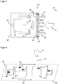
- Figure 1 shows a schematic sectional illustration of a camera 10.
- Receiving light 12 from a detection area 14 impinges on receiving optics 16, which guides the receiving light 12 to an image sensor 18.
- the optical elements of the receiving optics 16 are preferably designed as an objective consisting of a plurality of lenses and other optical elements such as diaphragms, prisms and the like, but are represented here simply by one lens.
- the camera 10 comprises an illumination unit which is shown in FIG Figure 1 is shown in the form of two light sources 20, for example LEDs or laser diodes.
- the lighting unit generates transmitted light 22, which is emitted into the detection area 14.
- a transmission optics (not shown) can be assigned to the light sources 20 in order to influence the transmission light 22 in a desired manner.
- a polarization filter 24 is arranged in the camera 10 in the exit area of the transmitted light 22 and in the entry area of the received light.
- the polarization filter 24 has a first surface 24a for polarizing the transmitted light 22 and a second surface 24b for polarizing the received light 12.
- the two surfaces 24a-b are preferably designed for linear polarization with a mutual offset of 90 °.
- the polarization filter 24 is arranged in a push-on frame 26, which also holds a front window 28 of the camera 10. In this way, a front of a housing 30 of the camera is closed.
- the push-on frame 26 with the polarization filter 24 and the front window 28 form a plug-on or additional module with which the polarization properties of the camera 10 are subsequently changed. There are several options for this: Switching between operation with polarization and without polarization by using an additional module as shown or a push-on frame 26 only with the front window 28, changing the polarization properties by exchanging it for an additional module with another polarization filter 24 or plugging the additional module in a different arrangement , in particular rotated by 180 ° about the optical axis of the receiving optics 16.
- the polarization filter 24 is arranged on the inside behind the windshield 28.
- a reversed order with polarization filter 24 on the outside is alternatively also possible.
- the polarization filter 24 is integrated in the front window 28, connected directly to it or acts as a front window 28.
- a control and evaluation unit 32 is connected to the lighting unit and the image sensor and is responsible for the control, evaluation and other coordination tasks in the camera 10. It therefore reads out image data from the image sensor 18 in order to process it and output it at an interface 34. Separate evaluations of the image data are also conceivable, in particular the decoding of code areas in the image data, whereby the camera 10 becomes a camera-based code reader.
- Figure 2 shows a three-dimensional view of a camera 10 with an additional module that is attached to the camera 10 by a snap mechanism.
- the camera 10 has a rectangular front, with variations such as rounded corners remaining possible.
- Clip-on frame 26 and windscreen 28 are adapted to the rectangular shape.
- a very flat frontal area is possible for the lighting unit and the polarization filter 24, and depending on the complexity of the receiving optics 16 and the electronics, for example the control and evaluation unit 32, an overall very flat device structure as shown or with an even smaller depth .
- the additional module or the push-on frame 26 in the embodiment according to FIG Figure 2 a plurality of snap hooks 36, here four by way of example, which snap onto the housing 30.
- a groove, a protrusion or the like can be provided there in order to give the snap hooks 36 better grip.
- the snap hooks 36 ensure a stable position of the add-on module and can still be removed at any time without tools to remove the add-on module or to attach another add-on module.
- Figure 3 shows a three-dimensional view of a camera 10 with an additional module, which is attached to the camera 10 by a magnetic holder.
- a hard magnetic material is located on the camera 10 or on the push-on frame 26.
- the opposite side is either made of a soft or a hard magnetic material.
- Active magnets are preferably only provided on the push-on frame 26, while the housing 30 has only magnetic material in the contact area provided. Then the camera 10 does not have to be modified at all, provided that its housing 30 contains sufficient magnetic metal.
- the Figures 2 and 3rd show two examples of a tool-free, very simple exchange mechanism for the add-on module.
- this for example hooks engaging in openings on the inside or a peripheral edge of the push-on frame 26 which snaps onto the front of the housing 30.
- the examples shown are therefore not conclusive.
- the push-on frame 26 can also be fixed with one or more screws. This is still easier than the conventional design because the polarization filter 24 is very easily accessible from the outside even when screws are used, without having to remove any further parts.
- screws are primarily considered in the case of special mechanical stresses caused by shaking or vibrating, and such conditions are generally to be avoided for a camera 10 anyway.
- the preferred principle of replacing the add-on module is tool-free and therefore in particular without screws.
- FIGS 4a-c show a front view of the camera 10.
- an additional module with a polarization filter 24 with three surfaces 24a-c and in Figure 4c the additional module according to Figure 4b attached rotated by 180 °.
- the push-on frame 26 is thus advantageously designed in such a way that a fastening rotated by 180 ° is also possible.
- light sources 20a-b of different colors are used, as indicated by hatching, for example red and blue.
- the light sources 20a-b can preferably be controlled separately and thereby enable variable lighting zones. In order to reduce the circuit complexity, it may be sufficient to only drive groups of light sources 20a-b together. In the embodiment shown, the light sources 20a-b of the same color could each form one of two groups. More groups or other groups are also conceivable, such as four groups according to the sectors, an inner and an outer group and the like. In this way, lighting can be generated in a targeted manner from specific directions, in particular in conjunction with image processing of the image data of the image sensor 18 in the control and evaluation unit 32, in order to find the best possible lighting setting for the respective application.
- an additional module with a polarization filter is plugged on, which has a first surface 24a with linear polarization in a first direction for the transmitted light 22 of the light sources 20a, here upwards as an example, a second surface 24b with linear polarization rotated by 90 ° for the reception light 12, here by way of example downwards, and has a third surface 24c without polarization for the transmitted light 22 of the light sources 20b.
- the colors of the light sources 20a-b can of course be distributed differently or only light sources 20a-b of one color can be used so that the choice of polarization is not tied to the choice of color.
- the configuration of the polarization filter 24 is only an advantageous example. More surfaces can be provided, in particular with different polarization directions, in order to make them selectable, and vice versa, only a single one Polarizing surface for all light sources 20a-b, in which the second surface 24b for the receiving light 12 is then located centrally.
- polarization filter 24 By dividing the polarization filter 24 into areas 24a-c with different polarization properties and controlling certain groups of light sources 20a-b, lighting zones and polarization properties can be selected without any further modification using another additional module. In combination with light sources 20a-b of several colors, polarization properties and / or lighting spectrum can be adjusted during operation.
- the resulting change in the polarization direction by 180 ° is irrelevant, firstly because the polarization direction of the received light 12 also rotates accordingly, and above all because it is only a matter of the relative rotation of the polarized direction by 90 ° between transmitted light 22 and received light 12.
- Figure 5 shows a schematic sectional view of a further embodiment of the camera 10.
- an additional presence sensor 38 is provided here, which detects whether a push-on frame 26 with a polarization filter 24 is attached or not.
- the presence sensor 38 is shown purely schematically and is constructed, for example, from one or more Hall sensors or inductive sensors which recognize a corresponding magnetized or metallic plug-on frame 26.
- a type of simple code can be created by changing presence signals, with which different push-on frames 26 and thus polarization filters 24 can be distinguished.
- Such a differentiated presence detection can also differentiate between different orientations, as they refer to Figure 4 have been explained.
- the identification of the respective polarization filter 24, or the recognition that no polarization filter 24 is attached, enables an automatic, targeted adjustment of camera parameters.
- Examples of such settings of the camera 10 are the brightness of the light sources 20 or the sensitivity (gain) of the image sensor 18.
- this is useful if the camera 10 is integrated into a higher-level system. For maintenance via the Internet or data transmission and evaluation from a distance, in particular in a cloud or another network, it may be important to know the current configuration of the camera 10 and to query the presence sensor 38 for this.
- Figure 6 shows a possible application of the camera 10 in assembly on a conveyor belt 40, which conveys objects 42, as indicated by the arrow 44, through the detection area 14 of the camera 10.
- the objects 42 can carry code areas 46 on their outer surfaces.
- the task of the camera 10 is to detect properties of the objects 42 and, in a preferred use as a code reader, to recognize the code areas 46, to read out, decode the codes attached there and to assign them to the respectively associated object 42.
- additional cameras 10, not shown are preferably used from different perspectives.
Landscapes
- Physics & Mathematics (AREA)
- General Physics & Mathematics (AREA)
- Engineering & Computer Science (AREA)
- Multimedia (AREA)
- Signal Processing (AREA)
- Optics & Photonics (AREA)
- Electromagnetism (AREA)
- Health & Medical Sciences (AREA)
- General Health & Medical Sciences (AREA)
- Toxicology (AREA)
- Theoretical Computer Science (AREA)
- Computer Vision & Pattern Recognition (AREA)
- Artificial Intelligence (AREA)
- Life Sciences & Earth Sciences (AREA)
- Chemical & Material Sciences (AREA)
- Analytical Chemistry (AREA)
- Biochemistry (AREA)
- Immunology (AREA)
- Pathology (AREA)
- Studio Devices (AREA)
- Blocking Light For Cameras (AREA)
- Structure And Mechanism Of Cameras (AREA)
Description
- Die Erfindung betrifft eine Kamera, insbesondere einen Codeleser, mit einem Bildsensor zur Erzeugung von Bilddaten aus Empfangslicht aus einem Erfassungsbereich nach dem Oberbegriff von Anspruch 1.
- In industriellen Anwendungen werden Kameras in vielfältiger Weise eingesetzt, um Objekteigenschaften automatisch zu erfassen, beispielsweise zur Inspektion oder Vermessung von Objekten. Dabei werden Bilder des Objekts aufgenommen und entsprechend der Aufgabe durch Bildverarbeitungsverfahren ausgewertet. Eine weitere Anwendung von Kameras ist das Lesen von Codes. Mit Hilfe eines Bildsensors werden Objekte mit den darauf befindlichen Codes aufgenommen, in den Bildern die Codebereiche identifiziert und dann dekodiert. Kamerabasierte Codeleser kommen problemlos auch mit anderen Codearten als eindimensionalen Strichcodes zurecht, die wie ein Matrixcode auch zweidimensional aufgebaut sind und mehr Informationen zur Verfügung stellen. Auch die automatische Texterfassung von gedruckten Adressen (OCR, Optical Character Recognition) oder Handschriften ist im Prinzip ein Lesen von Codes. Typische Anwendungsgebiete von Codelesern sind Supermarktkassen, die automatische Paketidentifikation, Sortierung von Postsendungen, die Gepäckabfertigung in Flughäfen und andere Logistikanwendungen.
- Eine häufige Erfassungssituation ist die Montage der Kamera über einem Förderband. Die Kamera nimmt während der Relativbewegung des Objektstroms auf dem Förderband Bilder auf und leitet in Abhängigkeit der gewonnenen Objekteigenschaften weitere Bearbeitungsschritte ein. Solche Bearbeitungsschritte bestehen beispielsweise in der an das konkrete Objekt angepassten Weiterverarbeitung an einer Maschine, die auf geförderte Objekte einwirkt, oder in einer Veränderung des Objektstroms, indem bestimmte Objekte im Rahmen einer Qualitätskontrolle aus dem Objektstrom ausgeschleust werden oder der Objektstrom in mehrere Teilobjektströme sortiert wird. Wenn die Kamera ein kamerabasierter Codeleser ist, werden die Objekte für eine korrekte Sortierung oder ähnliche Bearbeitungsschritte anhand der angebrachten Codes identifiziert.
- Um von variablen Lichtbedingungen unabhängig zu sein, verwenden viele industrielle Kamerasysteme eine eigene Beleuchtung. Für einen besseren Umgang mit glänzenden oder spiegelnden Objekten wird polarisiertes Licht verwendet. Dabei sind Sende- und Empfangspfad jeweils mit einem linearen Polarisationsfilter versehen. Die Ausrichtung der beiden Polarisationsfilter ist um 90° gedreht. Bei industriellen Kameras sind die Polarisationsfilter fest in dem Kamerasystem verbaut. Nachträglicher Einbau oder Austausch sind allenfalls möglich, wenn dafür das Gerät auseinandergebaut und eine die Front schützende Haube der Kamera abgeschraubt wird.
- Aus der
DE 10 2010 014 783 A1 ist ein Barcodescanner bekannt, in dessen Strahlengang für die Sende- und Empfangslichtstrahlen ein Dünnfilm-Polarisationsfilter angeordnet ist. - Die
US 9 033 237 B1 - In der
US 9 542 583 B2 - Die
WO 2015/019370 A1 befasst sich mit einem weiteren Barcodescanner mit Polarisationsfiltern, wobei das Polarisationsfilter des Lichtsenders einen Teil des Laserstrahls polarisiert und für einen weiteren Teil des Laserstrahls durchsichtig ist. - Bei allen diesen herkömmlichen Vorrichtungen ist ein Austausch des Polarisationsfilters nicht vorgesehen.
- In der
JP06222430A1 - Bekannt sind weiterhin Polarisationsfilter für Fotoapparate, die auf das Objektiv aufgesetzt werden. Das betrifft dann aber allein den Empfangsstrahlengang.
- Es ist daher Aufgabe der Erfindung, die Erfassung mit einer Kamera zu verbessern.
- Diese Aufgabe wird durch eine Kamera nach Anspruch 1 gelöst. Die Kamera erzeugt mit einem Bildsensor Bilddaten aus Empfangslicht. Eine Beleuchtungseinheit mit mindestens einer Lichtquelle beleuchtet dafür den Erfassungsbereich der Kamera. Ein Polarisationsfilter polarisiert Sendelicht und Empfangslicht. Das Polarisationsfilter ist vorzugsweise dafür ausgebildet, eine lineare Polarisation zu erzeugen, und zwar für Empfangslicht und Sendelicht um 90° zueinander versetzt.
- Die Erfindung geht nun von dem Grundgedanken aus, das Polarisationsfilter nachträglich auszutauschen. Dabei soll der Begriff Austausch das Hinzufügen oder Entfernen, also ein Umrüsten von polarisiertem zu nicht polarisiertem Licht und umgekehrt, ebenso umfassen wie den Wechsel auf ein anderes Polarisationsfilter oder einen anderen Einbau des zuvor schon verbauten Polarisationsfilters, um anders polarisiertes Licht zu erhalten. Um den Austausch erheblich zu vereinfachen oder überhaupt erst möglich zu machen, ist das Polarisationsfilter als nachträglich von außen austauschbares Zusatzmodul ausgebildet.
- Die Erfindung hat den Vorteil, dass durch den Austausch eine schnelle, flexible Adaption an neue Anforderungen oder neue Anwendungen möglich ist. Der Wechsel erfolgt sehr schnell, ohne Werkzeug, und es bedarf dazu keinerlei besonderer Qualifikation.
- Das Polarisationsfilter ist bevorzugt als Aufsteckmodul mit einer Schnappverbindung ausgebildet. Dazu sind beispielsweise Schnapphaken an dem Aufsteckmodul vorgesehen. Die Kamera beziehungsweise deren Gehäuse kann an seiner Front passende Aufnahmen, einen Überstand oder eine Nut zum Einhaken aufweisen. Vorzugsweise ist aber dem Design der Kamera ohne Zusatzmodul nicht anzusehen, dass ein Zusatzmodul angebracht werden kann. Die Nachrüstung für polarisiertes Licht durch das Zusatzmodul ist dann gänzlich nachträglich und völlig optional möglich.
- Das Polarisationsfilter ist vorzugsweise als Aufsteckmodul mit einer Magnetverbindung ausgebildet. Dazu können Magnete an dem Zusatzmodul und der Kamera vorgesehen sein, oder es befinden sich Magnete nur an einer Seite, während die andere Seite ein magnetisches Material aufweist. Besonders bevorzugt sind die Magnete auf Seiten des Zusatzmoduls, denn dann benötigt die Kamera lediglich an der Frontseite ihres Gehäuses entsprechende metallische Bereiche, was auch ohne besonderes Design für das Zusatzmodul häufig der Fall ist.
- Das Polarisationsfilter ist bevorzugt vor einer Frontscheibe der Kamera angeordnet. Die Kamera braucht also gar nicht verändert oder geöffnet zu werden, um das Zusatzmodul anzufügen. Alternativ weist das Zusatzmodul selbst die Frontscheibe auf. Hier sind dann beide Reihenfolgen mit Polarisationsfilter innen und Frontscheibe außen oder umgekehrt denkbar. Außerdem ist vorstellbar, das Polarisationsfilter in die Frontscheibe zu integrieren. Um ein solches Zusatzmodul anzubringen, wird die Frontscheibe durch das Zusatzmodul ersetzt. Wenn die Frontscheibe schon werkzeuglos befestigbar ist, beispielsweise durch einen Schnapp- oder Magnetmechanismus, ist dies sehr rasch und problemlos möglich.
- Das Zusatzmodul weist vorzugsweise einen Wechselrahmen auf, der ein Gehäuse der Kamera zu dessen Fronseite hin abschließt. Der Wechselrahmen sitzt zur Kamera hin auf einem Gehäuse und/oder einer Leiterkarte der Kamera auf. Nach außen hin schließt die Frontscheibe auf dem Wechselrahmen die Kamera, wobei eine Öffnung für ein Empfangsobjektiv verbleiben kann. Das Polarisationsfilter befindet sich je nach Ausführungsform innen oder außen am Wechselrahmen, wobei für das Polarisationsfilter die Positionen innerhalb und außerhalb der Frontscheibe sowie darin integriert möglich sind. Der Wechselrahmen umgibt vorzugsweise die Lichtquellen der Beleuchtungseinheit.
- Das Zusatzmodul ist bevorzugt rechteckig. Damit ist es besonders geeignet für eine im Wesentlichen quaderförmige Kamera, die ihre frontale, rechteckige Seite insgesamt oder doch weitgehend für eine Frontscheibe mit Lichtaustritt der Beleuchtungseinheit oder weitere Beleuchtungen etwa für eine Zielvorrichtung beziehungsweise eine Leuchtanzeige oder ein projiziertes Benutzerfeedback nutzt. Ein Zusatzmodul mit Wechselrahmen bildet dann die rechteckige Frontseite.
- Die Beleuchtungseinheit weist bevorzugt mehrere separat ansteuerbare Gruppen von Lichtquellen auf. Jede der vorzugsweise gleich großen Gruppen umfasst mindestens eine Lichtquelle. Durch gezielte Aktivierung oder Intensitätsanpassung der Gruppen entstehen unterschiedliche Beleuchtungsszenarien, die durch Parameter vorgegeben, aber auch durch Feedback einer Auswertung der Bilddaten eingestellt oder eingelernt werden können. Vorzugsweise sind vier Gruppen je Kante oder Ecke eines als rechteckiger Rahmen ausgebildeten Umlenkelements vorgesehen. Dadurch wird dann durch einzelne Ansteuerung der Gruppen die Beleuchtung aus allen vier Richtungen veränderbar.
- Die Lichtquellen einer Gruppe weisen bevorzugt eine andere Farbe auf als die Lichtquellen einer anderen Gruppe. Es gibt daher mindestens zwei Gruppen von Lichtquellen und mindestens zwei Farben. Möglich sind aber auch mehr Gruppen und mehr Farben, wobei nicht alle Gruppen unterschiedliche Farben aufweisen müssen. Manche Strukturen, insbesondere Codierungen bestimmter Farben auf bestimmtem Grund, lassen sich besser in einem passenden Beleuchtungsspektrum lesen. Das kann durch Einstellen einer Farbe für die Lichtquellen, aber auch Vermischen von Farben erreicht werden. Je nach Ausführungsform sind verschiedenfarbige Lichtquellen oder in ihrer Farbe umschaltbare Lichtquellen vorgesehen, wie mehrfarbige LEDs.
- Das Zusatzmodul ist bevorzugt mit einer ersten Fläche zum Polarisieren des Sendelichts und einer zweiten Fläche zum Polarisieren des Empfangslichts ausgebildet. Die Polarisationsrichtung der beiden Flächen ist vorzugsweise um 90° gegeneinander verdreht. Das sorgt dafür, dass Glanzreflexe ohne Polarisationsdrehung praktisch nicht erfasst werden. Die beiden Flächen liegen besonders bevorzugt in derselben Ebene. Dadurch wird ein sehr kompakter Aufbau möglich.
- Das Zusatzmodul weist bevorzugt eine Fläche für den Durchtritt von Sendelicht ohne Polarisierung auf. Das ist einerseits nützlich, wenn mehrere Lichtquellen oder Gruppen von Lichtquellen separat ansteuerbar sind. Durch Aktivierung entsprechend an einer polarisierenden oder nicht polarisierenden Fläche des Zusatzmoduls angeordneter Lichtquellen wird gezielt entsprechendes Sendelicht erzeugt. Bei mehrfarbigen Lichtquellen lässt sich auch die Farbe oder eine Kombination aus Farbe und Polarisation wählen. Vorstellbar ist auch eine weitere Fläche, die Sendelicht polarisiert, jedoch mit anderer Polarisationsrichtung als die erste Fläche. Dann lässt sich auswählen, ob Glanzreflexe bei Übereinstimmung der sende- und empfangsseitigen Polarisationsrichtung exklusiv durchgelassen oder bei Versatz um 90° gezielt weggefiltert werden. Andererseits kann die Auswahl des Sendelichts nicht durch Ansteuerung von bestimmten Lichtquellen, sondern durch bestimmte Anordnung des Zusatzmoduls bezüglich der Lichtquellen erfolgen.
- Das Zusatzmodul ist vorzugsweise in verschiedenen Orientierungen an der Kamera anbringbar. Dabei ist insbesondere an eine Drehung um 180°, je nach Form der Kamera und des Zusatzmoduls auch 90° oder einen anderen Winkel zu denken. Die Polarisationsfilter sind dann vorzugsweise gerade nicht entsprechend drehsymmetrisch in dem Zusatzmodul angeordnet. Über die Orientierung des Zusatzmoduls bei dessen Anbringung kann gewählt werden, welche Lichtquellen polarisiert werden und welche nicht, oder es wird so eine bestimmte Polarisationsrichtung festgelegt.
- Die Kamera weist bevorzugt einen Anwesenheitssensor auf, um zu erkennen, ob ein Zusatzmodul im Strahlengang der Kamera angeordnet ist. Der Anwesenheitssensor kann auch die Information liefern, welches Zusatzmodul aufgesteckt ist, beziehungsweise welche Polarisationen und Polarisationsrichtungen das Zusatzmodul erzeugt. Der Anwesenheitssensor ist beispielsweise auf Basis mindestens eines Hallsensors oder eines induktiven Sensors aufgebaut, welcher den Rahmen des Polarisationsfilters erkennt. Durch Mehrfachanordnungen und Materialien beziehungsweise Materialdicken kann eine Art einfache Codierung zur Unterscheidung verschiedener Zusatzmodule und/oder Orientierungen vorgegeben werden. Der Anwesenheitssensor schafft die Möglichkeit, Steuerungen wie eine Leistung des Lichtsenders, eine Belichtungszeit oder eine Empfindlichkeit des Bildsensors gezielt und automatisch an das Zusatzmodul anzupassen. Außerdem kann so aus einem übergeordneten System abgefragt werden, welche Konfiguration der Kamera mit ihrem aktuell erfassten Zusatzmodul vorliegt.
- Die Kamera weist bevorzugt eine Steuer- und Auswertungseinheit auf, die dafür ausgebildet ist, in den Bilddaten Codebereiche zu identifizieren und deren Codeinhalt auszulesen. Damit wird die Kamera zu einem kamerabasierten Codeleser für Barcodes und/oder 2D-Codes nach diversen Standards, gegebenenfalls auch für eine Texterkennung (OCR, Optical Character Reading). Eine Steuer- und Auswertungseinheit ist im Übrigen vorzugsweise auch ohne Codelesefunktionalität vorgesehen, welche die diversen Aufgaben in der Kamera steuert und ausführt, wie die Bildaufnahme, eine Beleuchtung, die Messung von tatsächlicher und benötigter Fokuslage und deren Anzeige.
- Die Erfindung wird nachstehend auch hinsichtlich weiterer Merkmale und Vorteile beispielhaft anhand von Ausführungsformen und unter Bezug auf die beigefügte Zeichnung näher erläutert. Die Abbildungen der Zeichnung zeigen in:
- Fig. 1
- eine schematische Schnittdarstellung einer Kamera mit Beleuchtung;
- Fig. 2
- eine dreidimensionale Ansicht einer Kamera mit einem Zusatzmodul, das durch einen Schnappmechanismus angebracht ist;
- Fig. 3
- eine dreidimensionale Ansicht einer Kamera mit einem Zusatzmodul, das durch einen Magnetmechanismus angebracht ist;
- Fig. 4a
- eine Frontalansicht einer Kamera ohne aufgestecktes Zusatzmodul;
- Fig. 4b
- eine Frontalansicht einer Kamera mit aufgestecktem Zusatzmodul;
- Fig. 4c
- eine Frontalansicht einer Kamera mit gegenüber
Figur 4b um 180° verdreht aufgestecktem Zusatzmodul; - Fig. 5
- eine schematische Schnittdarstellung einer Kamera mit Anwesenheitssensor für ein Zusatzmodul; und
- Fig. 6
- eine dreidimensionale Ansicht einer beispielhaften Anwendung der Kamera in Montage an einem Förderband.
-
Figur 1 zeigt eine schematische Schnittdarstellung einer Kamera 10. Empfangslicht 12 aus einem Erfassungsbereich 14 trifft auf eine Empfangsoptik 16, die das Empfangslicht 12 auf einen Bildsensor 18 führt. Die optischen Elemente der Empfangsoptik 16 sind vorzugsweise als Objektiv aus mehreren Linsen und anderen optischen Elementen wie Blenden, Prismen und dergleichen ausgestaltet, hier aber vereinfachend nur durch eine Linse repräsentiert. - Um den Erfassungsbereich 14 während einer Aufnahme der Kamera 10 auszuleuchten, umfasst die Kamera 10 eine Beleuchtungseinheit, die in
Figur 1 in Form zweier Lichtquellen 20 dargestellt ist, beispielsweise LEDs oder auch Laserdioden. Die Beleuchtungseinheit erzeugt Sendelicht 22, das in den Erfassungsbereich 14 ausgesandt wird. Den Lichtquellen 20 kann eine nicht gezeigte Sendeoptik zugeordnet sein, um das Sendelicht 22 in einer gewünschten Weise zu beeinflussen. - Im Austrittsbereich des Sendelichts 22 und im Eintrittsbereich des Empfangslichts ist in der Kamera 10 ein Polarisationsfilter 24 angeordnet. Das Polarisationsfilter 24 weist eine erste Fläche 24a zum Polarisieren des Sendelichts 22 und eine zweite Fläche 24b zum Polarisieren des Empfangslichts 12 auf. Vorzugsweise sind die beiden Flächen 24a-b für eine lineare Polarisation mit gegenseitigem Versatz von 90° ausgebildet.
- Das Polarisationsfilter 24 ist in einem Aufsteckrahmen 26 angeordnet, der außerdem eine Frontscheibe 28 der Kamera 10 hält. Auf diese Weise wird eine Frontseite eines Gehäuses 30 der Kamera geschlossen. Der Aufsteckrahmen 26 mit dem Polarisationsfilter 24 und der Frontscheibe 28 bildet ein Aufsteck- oder Zusatzmodul, mit dem nachträglich die Polarisationseigenschaften der Kamera 10 verändert werden. Dazu gibt es mehrere Möglichkeiten: Wechsel zwischen einem Betrieb mit Polarisation und ohne Polarisation durch Verwendung eines Zusatzmoduls wie dargestellt oder eines Aufsteckrahmens 26 lediglich mit der Frontscheibe 28, Wechsel der Polarisationseigenschaften durch Austausch gegen ein Zusatzmodul mit anderem Polarisationsfilter 24 oder Aufstecken des Zusatzmoduls in anderer Anordnung, insbesondere um 180° um die optische Achse der Empfangsoptik 16 verdreht.
- In
Figur 1 ist das Polarisationsfilter 24 innen hinter der Frontscheibe 28 angeordnet. Eine vertauschte Reihenfolge mit Polarisationsfilter 24 außen ist alternativ auch möglich. In einer weiteren Ausführungsform ist das Polarisationsfilter 24 in die Frontscheibe 28 integriert, direkt damit verbunden oder fungiert als Frontscheibe 28. - Eine Steuer- und Auswertungseinheit 32 ist mit der Beleuchtungseinheit und dem Bildsensor verbunden und für die Steuerungs-, Auswertungs- und sonstigen Koordinierungsaufgaben in der Kamera 10 zuständig. Sie liest also Bilddaten des Bildsensors 18 aus, um sie zu verarbeiten und an einer Schnittstelle 34 auszugeben. Es sind auch eigene Auswertungen der Bilddaten denkbar, insbesondere das Decodieren von Codebereichen in den Bilddaten, womit die Kamera 10 zu einem kamerabasierten Codeleser wird.
-
Figur 2 zeigt eine dreidimensionale Ansicht einer Kamera 10 mit einem Zusatzmodul, dass durch einen Schnappmechanismus auf die Kamera 10 aufgesteckt wird. Die Kamera 10 weist eine rechteckige Front auf, wobei Variationen wie gerundete Ecken möglich bleiben. Aufsteckrahmen 26 und Frontscheibe 28 sind an die rechteckige Form angepasst. Wie zu erkennen, ist ein sehr flacher Frontalbereich für die Beleuchtungseinheit und das Polarisationsfilter 24 möglich, und je nach Komplexität der Empfangsoptik 16 und der Elektronik, etwa der Steuer- und Auswertungseinheit 32, auch ein insgesamt sehr flacher Geräteaufbau wie dargestellt oder mit noch geringerer Bautiefe. - Das Zusatzmodul beziehungsweise der Aufsteckrahmen 26 weist in der Ausführungsform gemäß
Figur 2 mehrere Schnapphaken 36 auf, hier beispielhaft vier, die an dem Gehäuse 30 einschnappen. Dort kann eine Rille, ein Überstand oder dergleichen vorgesehen sein, um den Schnapphaken 36 besseren Halt zu geben. Die Schnapphaken 36 sorgen für eine stabile Position des Zusatzmoduls und sind dennoch jederzeit ohne Werkzeug lösbar, um das Zusatzmodul zu entfernen oder ein anderes Zusatzmodul anzubringen. -
Figur 3 zeigt eine dreidimensionale Ansicht einer Kamera 10 mit einem Zusatzmodul, das durch eine Magnethalterung an der Kamera 10 angebracht wird. Bei diesem magnetischen Befestigungskonzept befindet sich an der Kamera 10 oder an dem Aufsteckrahmen 26 ein hartmagnetisches Material. Die Gegenseite ist entweder mit einem weich- oder einem hartmagnetischen Material ausgeführt. Bevorzugt sind nur an dem Aufsteckrahmen 26 aktive Magnete vorgesehen, während das Gehäuse 30 im vorgesehenen Kontaktbereich lediglich magnetisches Material aufweist. Dann muss nämlich die Kamera 10 gar nicht weiter modifiziert werden, sofern ihr Gehäuse 30 ausreichend magnetisches Metall enthält. - Die
Figuren 2 und3 zeigen zwei Beispiele für einen werkzeuglosen, sehr einfachen Austauschmechanismus des Zusatzmoduls. Es gibt dafür weitere Möglichkeiten, etwa innen in Öffnungen eingreifende Haken oder einen umlaufenden, auf die Frontseite des Gehäuses 30 aufschnappenden Rand des Aufsteckrahmens 26. Die gezeigten Beispiele sind also nicht abschließend. Prinzipiell kann der Aufsteckrahmen 26 auch mit einer oder mehreren Schrauben fixiert werden. Das ist immer noch einfacher als der herkömmliche Aufbau, weil das Polarisationsfilter 24 auch bei Verwendung von Schrauben sehr einfach von außen zugänglich ist, ohne weitere Teile abnehmen zu müssen. Schrauben kommen aber in erster Linie bei besonderer mechanischer Beanspruchung durch Rütteln oder Vibrieren in Frage, und solche Bedingungen sind für eine Kamera 10 ohnehin in der Regel zu meiden. Das bevorzugte Prinzip des Austauschs des Zusatzmoduls ist werkzeuglos und damit insbesondere ohne Schrauben. - Die
Figuren 4a-c zeigen eine Frontalansicht der Kamera 10. Dabei ist inFigur 4a kein Zusatzmodul, inFigur 4b ein Zusatzmodul mit einem Polarisationsfilter 24 mit drei Flächen 24a-c und inFigur 4c das Zusatzmodul gemäßFigur 4b um 180° verdreht aufgesteckt. Der Aufsteckrahmen 26 ist also vorteilhafterweise so ausgebildet, dass auch eine um 180° gedrehte Befestigung möglich wird. - In der gezeigten Ausführungsform sind Lichtquellen 20a-b unterschiedlicher Farben verwendet, wie durch Schraffuren angedeutet, beispielsweise rot und blau. Alternativ ist denkbar, mehrere Farben schon innerhalb einer jeweiligen Lichtquelle 20a-b zu ermöglichen, wie bei einer mehrfarbigen LED, oder es werden Lichtquellen 20a-b unterschiedliche Farben nebeneinander eingesetzt, die wahlweise für bestimmte Farben aktiviert werden. Durch Farbwechsel werden manche Strukturen besser erkennbar, etwa je nach Druckfarbe und Untergrund Codes besser in rotem oder in blauem Licht gelesen.
- Vorzugsweise sind die Lichtquellen 20a-b getrennt ansteuerbar und ermöglichen dadurch variable Beleuchtungszonen. Um die Schaltungskomplexität zu verringern, kann es genügen, Gruppen von Lichtquellen 20a-b nur gemeinsam anzusteuern. In der gezeigten Ausführungsform könnten die jeweils gleichfarbigen Lichtquellen 20a-b jeweils eine von zwei Gruppen bilden. Mehr Gruppen oder andere Gruppen sind ebenso denkbar, etwa vier Gruppen entsprechend den Sektoren, eine innere und eine äußere Gruppe und dergleichen. Auf diese Weise lässt sich gezielt eine Beleuchtung aus bestimmten Richtungen erzeugen, insbesondere im Zusammenspiel mit einer Bildverarbeitung der Bilddaten des Bildsensors 18 in der Steuer- und Auswertungseinheit 32, um auf diesem Weg eine für die jeweilige Anwendung bestmögliche Beleuchtungseinstellung zu finden.
- In der Konfiguration gemäß
Figur 4a ist kein Zusatzmodul mit Polarisationsfilter 24 angebracht, beispielsweise ein Aufsteckrahmen nur mit der Frontscheibe 28. Die Kamera 10 arbeitet folglich mit nicht polarisiertem Sendelicht 22 und Empfangslicht 12. Verschiedene Farben und/oder Beleuchtungszonen bleiben möglich. - In der Konfiguration gemäß
Figur 4b ist ein Zusatzmodul mit einem Polarisationsfilter aufgesteckt, das eine erste Fläche 24a mit linearer Polarisation in einer ersten Richtung für das Sendelicht 22 der Lichtquellen 20a, hier beispielhaft nach oben, eine zweite Fläche 24b mit um 90° verdrehter linearer Polarisation für das Empfangslicht 12, hier beispielhaft nach unten, und einer dritte Fläche 24c ohne Polarisation für das Sendelicht 22 der Lichtquellen 20b aufweist. Durch Aktivierung der oberen Lichtquellen 20a oder der unteren Lichtquellen 20b ist dann möglich, Bilder mit oder ohne polarisiertes Sendelicht aufzunehmen. Dabei können natürlich die Farben der Lichtquellen 20a-b anders verteilt sein oder nur Lichtquellen 20a-b einer Farbe verwendet werden, damit die Wahl der Polarisation nicht an die Wahl der Farbe gebunden ist. Ohnehin ist die Ausgestaltung des Polarisationsfilters 24 nur ein vorteilhaftes Beispiel. Es können mehr Flächen vorgesehen sein, insbesondere mit jeweils unterschiedlichen Polarisationsrichtungen, um auch diese auswählbar zu machen, und umgekehrt lediglich eine einzige polarisierende Fläche für alle Lichtquellen 20a-b, in der sich dann zentral die zweite Fläche 24b für das Empfangslicht 12 befindet. - Durch Aufteilung des Polarisationsfilters 24 in Flächen 24a-c mit unterschiedlichen Polarisationseigenschaften und Ansteuerung bestimmter Gruppen von Lichtquellen 20a-b lassen sich so ohne weiteren Umbau mit einem anderen Zusatzmodul Beleuchtungszonen und Polarisationseigenschaften auswählen. In Kombination mit Lichtquellen 20a-b mehrerer Farben sind im Betrieb Polarisationseigenschaften und/oder Beleuchtungsspektrum anpassbar.
- Wenn die Variabilität durch ein und dasselbe Zusatzmodul nicht ausreicht, kann es durch ein anderes Zusatzmodul ausgetauscht werden, das die gewünschten Eigenschaften mitbringt. Eine besonders vorteilhafte Ausführungsform dafür illustriert die Konfiguration gemäß
Figur 4c . Dabei wird kein neues Zusatzmodul aufgesteckt, sondern das Zusatzmodul ausFigur 4b um 180° gedreht. Dann wird mit vertauschten Rollen das Sendelicht 22 der oberen Lichtquellen 20a von der Fläche 24c unpolarisiert transmittiert und das Sendelicht 22 der unteren Lichtquellen 20b von der Fläche 20a linear polarisiert. Die dabei auftretende Änderung der Polarisationsrichtung um 180° spielt keine Rolle, zum einen, weil sich auch die Polarisationsrichtung des Empfangslichts 12 entsprechend dreht, und vor allem weil es nur um die relative Verdrehung der Polarisationsrichtung um 90° zwischen Sendelicht 22 und Empfangslicht 12 ankommt. -
Figur 5 zeigt eine schematische Schnittdarstellung einer weiteren Ausführungsform der Kamera 10. Im Unterschied zuFigur 1 ist hier ein zusätzlicher Anwesenheitssensor 38 vorgesehen, welcher erkennt, ob ein Aufsteckrahmen 26 mit einem Polarisationsfilter 24 aufgesteckt ist oder nicht. Der Anwesenheitssensor 38 ist nur rein schematisch gezeigt und beispielsweise aus einem oder mehreren Hall-Sensoren oder induktiven Sensoren aufgebaut, die einen entsprechenden magnetisierten oder metallischen Aufsteckrahmen 26 erkennen. Durch Erfassung an mehreren Punkten und entsprechende Ausgestaltung von Material und Geometrie des Aufsteckrahmens 26 an den korrespondierenden Stellen kann eine Art einfacher Code durch veränderte Anwesenheitssignale geschaffen werden, mit dem verschiedene Aufsteckrahmen 26 und damit Polarisationsfilter 24 unterschieden werden. Eine solche differenzierte Anwesenheitserfassung kann auch unterschiedliche Orientierungen unterscheiden, wie sie unter Bezugnahme auf dieFigur 4 erläutert wurden. - Die Identifizierung des jeweiligen Polarisationsfilters 24, beziehungsweise die Erkennung, dass kein Polarisationsfilter 24 aufgesteckt ist, ermöglicht eine automatische, gezielte Anpassung von Kameraparametern. Beispiele für solche Einstellungen der Kamera 10 sind die Helligkeit der Lichtquellen 20 oder die Empfindlichkeit (Gain) des Bildsensors 18. Außerdem ist dies nützlich, wenn die Kamera 10 in ein übergeordnetes System eingebunden ist. Für eine Wartung per Internet oder eine Datenübertragung und -auswertung aus der Ferne insbesondere in einer Cloud oder einem anderen Netzwerk kann es wichtig sein, die aktuelle Konfiguration der Kamera 10 zu kennen und dafür den Anwesenheitssensor 38 abzufragen.
-
Figur 6 zeigt eine mögliche Anwendung der Kamera 10 in Montage an einem Förderband 40, welches Objekte 42, wie durch den Pfeil 44 angedeutet, durch den Erfassungsbereich 14 der Kamera 10 fördert. Die Objekte 42 können an ihren Außenflächen Codebereiche 46 tragen. Aufgabe der Kamera 10 ist, Eigenschaften der Objekte 42 zu erfassen und in einem bevorzugten Einsatz als Codeleser die Codebereiche 46 zu erkennen, die dort angebrachten Codes auszulesen, zu dekodieren und dem jeweils zugehörigen Objekt 42 zuzuordnen. Um auch seitlich angebrachte Codebereiche 48 zu erkennen, werden vorzugsweise zusätzliche, nicht dargestellte Kameras 10 aus unterschiedlicher Perspektive eingesetzt.
Claims (12)
- Kamera (10), insbesondere Codeleser, mit einem Bildsensor (18) zur Erzeugung von Bilddaten aus Empfangslicht (12) aus einem Erfassungsbereich (14), einer Beleuchtungseinheit mit mindestens einer Lichtquelle (20) zum Ausleuchten des Erfassungsbereichs (14) mit Sendelicht (22) und einem Polarisationsfilter (24), welches das Sendelicht (22) und das Empfangslicht (12) polarisiert, mehrere Flächen (24a-c) mit unterschiedlichen Polarisationseigenschaften aufweist und als nachträglich von außen austauschbares Zusatzmodul (26, 24) ausgebildet ist,
dadurch gekennzeichnet,
dass das Zusatzmodul (26, 24) in verschiedenen Orientierungen an der Kamera (10) anbringbar ist. - Kamera (10) nach Anspruch 1,
wobei das Polarisationsfilter (24) als Aufsteckmodul mit einer Schnappverbindung (36) ausgebildet ist. - Kamera (10) nach Anspruch 1,
wobei das Polarisationsfilter (24) als Aufsteckmodul mit einer Magnetverbindung ausgebildet ist. - Kamera (10) nach einem der vorhergehenden Ansprüche,
wobei das Polarisationsfilter (24) vor einer Frontscheibe (28) der Kamera (10) angeordnet ist, oder wobei das Zusatzmodul (26, 24, 28) die Frontscheibe (28) aufweist. - Kamera (10) nach einem der vorhergehenden Ansprüche,
wobei das Zusatzmodul (26, 24) einen Wechselrahmen (26) aufweist, der ein Gehäuse (30) der Kamera (10) zu dessen Fronseite hin abschließt. - Kamera (10) nach einem der vorhergehenden Ansprüche,
wobei das Zusatzmodul (26, 24) rechteckig ist. - Kamera (10) nach einem der vorhergehenden Ansprüche,
wobei die Beleuchtungseinheit mehrere separat ansteuerbare Gruppen von Lichtquellen (20a-b) aufweist. - Kamera (10) nach Anspruch 7,
wobei die Lichtquellen (20a) einer Gruppe eine andere Farbe aufweisen als die Lichtquellen (20b) einer anderen Gruppe. - Kamera (10) nach einem der vorhergehenden Ansprüche,
wobei das Zusatzmodul (26, 24) mit einer ersten Fläche (24a) zum Polarisieren des Sendelichts (22) und einer zweiten Fläche (24b) zum Polarisieren des Empfangslichts (12) ausgebildet ist. - Kamera (10) nach Anspruch 9,
wobei das Zusatzmodul (26, 24) eine Fläche (24c) für den Durchtritt von Sendelicht (22) ohne Polarisierung aufweist. - Kamera (10) nach einem der vorhergehenden Ansprüche
mit einem Anwesenheitssensor (38) zur Erkennung, ob ein Zusatzmodul (26, 24) im Strahlengang der Kamera (10) angeordnet ist. - Kamera (10) nach einem der vorhergehenden Ansprüche,
die eine Steuer- und Auswertungseinheit (32) aufweist, die dafür ausgebildet ist, in den Bilddaten Codebereiche zu identifizieren und deren Codeinhalt auszulesen.
Applications Claiming Priority (1)
| Application Number | Priority Date | Filing Date | Title |
|---|---|---|---|
| DE102018104906.4A DE102018104906B3 (de) | 2018-03-05 | 2018-03-05 | Kamera |
Publications (2)
| Publication Number | Publication Date |
|---|---|
| EP3537334A1 EP3537334A1 (de) | 2019-09-11 |
| EP3537334B1 true EP3537334B1 (de) | 2020-06-03 |
Family
ID=64332799
Family Applications (1)
| Application Number | Title | Priority Date | Filing Date |
|---|---|---|---|
| EP19154265.3A Active EP3537334B1 (de) | 2018-03-05 | 2019-01-29 | Kamera |
Country Status (7)
| Country | Link |
|---|---|
| US (1) | US20190273852A1 (de) |
| EP (1) | EP3537334B1 (de) |
| JP (1) | JP2019197532A (de) |
| KR (1) | KR102172973B1 (de) |
| CN (1) | CN110231749A (de) |
| DE (1) | DE102018104906B3 (de) |
| DK (1) | DK3537334T3 (de) |
Families Citing this family (12)
| Publication number | Priority date | Publication date | Assignee | Title |
|---|---|---|---|---|
| JP6363903B2 (ja) * | 2014-07-31 | 2018-07-25 | 株式会社キーエンス | 光学的情報読取装置 |
| CN110730345B (zh) * | 2019-10-11 | 2022-09-02 | 京东方科技集团股份有限公司 | 图像显示方法、图像识别方法、装置、介质、设备及系统 |
| US11665410B2 (en) * | 2020-03-10 | 2023-05-30 | Cognex Corporation | Modular vision systems and methods |
| KR102377553B1 (ko) * | 2020-09-16 | 2022-03-22 | 한국생산기술연구원 | 마이크로버블 크기 측정방법 |
| JP7114106B2 (ja) * | 2020-11-04 | 2022-08-08 | 有限会社東奥電気 | 医療器具二次元コード読取装置 |
| DE102021001523A1 (de) * | 2021-03-24 | 2022-09-29 | Oerlikon Surface Solutions Ag | Data Matrix Code Scanbox und deren Verwendung |
| US12067450B2 (en) * | 2022-08-29 | 2024-08-20 | Hand Held Products, Inc. | Near co-axial polarized illuminator apparatuses and uses thereof |
| EP4394364B1 (de) | 2022-11-04 | 2025-12-17 | Contemporary Amperex Technology (Hong Kong) Limited | Vorrichtung und system zur qualitätsbestimmung mit graviertem code |
| JP2024078083A (ja) * | 2022-11-29 | 2024-06-10 | 株式会社豊田自動織機 | 撮像装置 |
| JPWO2024262049A1 (de) * | 2023-06-22 | 2024-12-26 | ||
| DE102024101764B3 (de) | 2024-01-22 | 2025-01-30 | Ifm Electronic Gmbh | Polarisationsfiltereinheit für ein Kamerasystem, ein Kamerasystem sowie ein Herstellungsverfahren |
| KR102896819B1 (ko) * | 2024-06-26 | 2025-12-05 | 주식회사 코어이미징 | 물류 자동화 시스템용 고속 및 고해상도 ToF 카메라 |
Family Cites Families (22)
| Publication number | Priority date | Publication date | Assignee | Title |
|---|---|---|---|---|
| JPH06222430A (ja) * | 1993-01-26 | 1994-08-12 | Fuji Photo Film Co Ltd | カメラ |
| JPH08240839A (ja) | 1995-03-01 | 1996-09-17 | Canon Inc | 撮像装置および撮像方法 |
| US7031081B2 (en) * | 2002-01-09 | 2006-04-18 | Robert Petroff | Matte box quick assembly system |
| JP4915314B2 (ja) * | 2007-08-23 | 2012-04-11 | オムロン株式会社 | 撮像装置および撮像制御方法 |
| US8508646B2 (en) * | 2008-12-22 | 2013-08-13 | Apple Inc. | Camera with internal polarizing filter |
| JP2010199931A (ja) * | 2009-02-25 | 2010-09-09 | Aiphone Co Ltd | カメラ付玄関子機 |
| US20100231511A1 (en) * | 2009-03-10 | 2010-09-16 | David L. Henty | Interactive media system with multi-directional remote control and dual mode camera |
| DE102010014783A1 (de) | 2010-04-13 | 2011-10-13 | Leuze Electronic Gmbh & Co. Kg | Optoelektronische Vorrichtung |
| KR101180345B1 (ko) * | 2010-05-06 | 2012-09-06 | (주)이즈미디어 | 카메라 모듈의 렌즈 포커스 조정 장치 |
| KR20120035618A (ko) * | 2010-10-06 | 2012-04-16 | 주식회사 만도 | 반사광 제거 모듈 |
| US8902293B2 (en) * | 2011-01-17 | 2014-12-02 | Panasonic Corporation | Imaging device |
| JP2012199819A (ja) * | 2011-03-22 | 2012-10-18 | Olympus Imaging Corp | 撮像装置、撮像方法及び撮像処理の制御プログラム |
| JP5875256B2 (ja) * | 2011-06-06 | 2016-03-02 | キヤノン株式会社 | 撮像装置及び交換レンズ、撮像装置の制御方法及び交換レンズの制御方法 |
| US10498933B2 (en) * | 2011-11-22 | 2019-12-03 | Cognex Corporation | Camera system with exchangeable illumination assembly |
| WO2015019370A1 (en) | 2013-08-06 | 2015-02-12 | Datalogic Ip Tech S.R.L. | Laser light beam scanning device for reading coded information |
| US9033237B1 (en) | 2013-10-26 | 2015-05-19 | Symbol Technologies, Inc. | Decoding DPM indicia with polarized illumination |
| KR20150064612A (ko) * | 2013-12-03 | 2015-06-11 | 이스턴 마스텍 주식회사 | 자동차용 후방 카메라 |
| DE202014102452U1 (de) * | 2014-05-26 | 2015-08-27 | Sick Ag | Kamera zur Aufnahme von Bilddaten |
| JP6363903B2 (ja) | 2014-07-31 | 2018-07-25 | 株式会社キーエンス | 光学的情報読取装置 |
| CN204215130U (zh) * | 2014-09-29 | 2015-03-18 | 杭州海康威视数字技术股份有限公司 | 一种滤光片切换装置和一种具有滤光片切换装置的摄像机 |
| KR101724428B1 (ko) * | 2015-06-17 | 2017-04-10 | 마이크로엑츄에이터(주) | 일체형 필터 교체장치 |
| CN206479753U (zh) * | 2017-02-21 | 2017-09-08 | 绍兴维肯光学科技有限公司 | 一种可调整镜头进光量且带有限位装置的减光滤镜 |
-
2018
- 2018-03-05 DE DE102018104906.4A patent/DE102018104906B3/de not_active Expired - Fee Related
-
2019
- 2019-01-29 DK DK19154265.3T patent/DK3537334T3/da active
- 2019-01-29 EP EP19154265.3A patent/EP3537334B1/de active Active
- 2019-02-18 US US16/278,442 patent/US20190273852A1/en not_active Abandoned
- 2019-02-26 KR KR1020190022704A patent/KR102172973B1/ko active Active
- 2019-02-26 CN CN201910141439.9A patent/CN110231749A/zh active Pending
- 2019-02-27 JP JP2019033739A patent/JP2019197532A/ja active Pending
Non-Patent Citations (1)
| Title |
|---|
| None * |
Also Published As
| Publication number | Publication date |
|---|---|
| DE102018104906B3 (de) | 2018-12-13 |
| KR102172973B1 (ko) | 2020-11-02 |
| US20190273852A1 (en) | 2019-09-05 |
| DK3537334T3 (da) | 2020-07-27 |
| JP2019197532A (ja) | 2019-11-14 |
| KR20190105508A (ko) | 2019-09-17 |
| CN110231749A (zh) | 2019-09-13 |
| EP3537334A1 (de) | 2019-09-11 |
Similar Documents
| Publication | Publication Date | Title |
|---|---|---|
| DE102018104906B3 (de) | Kamera | |
| DE102018102917B3 (de) | Kamera und Verfahren zur Fokusverstellung | |
| DE69326755T2 (de) | Leser zum dekodieren zwei-dimensionaler optischer information | |
| DE69519798T2 (de) | Vorrichtung zum drucken von daten aus mehreren miteinander verbundenen quellen auf ein vorbedrucktes dokument | |
| EP2546776B1 (de) | Kamerabasierter Codeleser und Verfahren zu dessen justierter Herstellung | |
| DE69025692T2 (de) | Bildlesegerät | |
| DE202018101209U1 (de) | Kamera | |
| DE102018103544B3 (de) | Kamera und Verfahren zur Erfassung von Bilddaten | |
| DE102019130963B3 (de) | Fokusmodul | |
| DE102013114863A1 (de) | Linse mit konstanter Vergrößerung für eine Kamera eines Visionssystems | |
| CH704296A2 (de) | Vorrichtung in der Spinnereivorbereitung zum Erkennen von Fremdteilen aus Kunststoff, wie Polypropylenbändchen, -gewebe und -folien u. dgl. | |
| EP4075394B1 (de) | Erfassung eines bewegten stromes von objekten | |
| DE102017119528A1 (de) | Bildgebungsmodul und -lesegerät zum Lesen eines Zieles über ein Sichtfeld durch Bilderfassung mit einer optisch markanten Anzeige einer Mittelzone des Sichtfeldes, und Verfahren dafür | |
| EP3718044B1 (de) | Codelesevorrichtung und verfahren zur online-verifikation eines codes | |
| DE112022006024T5 (de) | Automatische brennpunkteinstellung für fixierte bildverarbeitungssysteme | |
| EP3591567A1 (de) | Optoelektronischer sensor und verfahren zur wiederholten optischen erfassung von objekten in unterschiedlichem objektabstand | |
| DE102017119282B4 (de) | Optische Abbildungsvorrichtungen und -verfahren | |
| EP2916258B1 (de) | 2d-barcode-scanner | |
| DE202009009493U1 (de) | Optoelektronischer Sensor zu Erfassung von Codes | |
| EP3687155A1 (de) | Modulare kameravorrichtung und verfahren zur optischen erfassung | |
| EP2511852B1 (de) | Beleuchtungsvorrichtung für einen kamerabasierten Codeleser | |
| EP1533045B1 (de) | Verfahren und Vorrichtung zur optimierten Sortierung von Altpapier und Altkarton | |
| DE102012104223A1 (de) | Verfahren und Vorrichtung zur optischen Erkennung in einer Sortieranlage | |
| EP3267367A1 (de) | Zählscheibenvorrichtung | |
| DE102015116568A1 (de) | Verfahren zur Analyse eines Objektes mit einer Bildaufnahmeeinheit in einer Fabrik- oder Prozessautomation sowie eine Bildaufnahmeeinrichtung zur Analyse eines Objektes in der Fabrik- oder Prozessautomation |
Legal Events
| Date | Code | Title | Description |
|---|---|---|---|
| PUAI | Public reference made under article 153(3) epc to a published international application that has entered the european phase |
Free format text: ORIGINAL CODE: 0009012 |
|
| STAA | Information on the status of an ep patent application or granted ep patent |
Free format text: STATUS: THE APPLICATION HAS BEEN PUBLISHED |
|
| AK | Designated contracting states |
Kind code of ref document: A1 Designated state(s): AL AT BE BG CH CY CZ DE DK EE ES FI FR GB GR HR HU IE IS IT LI LT LU LV MC MK MT NL NO PL PT RO RS SE SI SK SM TR |
|
| AX | Request for extension of the european patent |
Extension state: BA ME |
|
| STAA | Information on the status of an ep patent application or granted ep patent |
Free format text: STATUS: REQUEST FOR EXAMINATION WAS MADE |
|
| 17P | Request for examination filed |
Effective date: 20191212 |
|
| RBV | Designated contracting states (corrected) |
Designated state(s): AL AT BE BG CH CY CZ DE DK EE ES FI FR GB GR HR HU IE IS IT LI LT LU LV MC MK MT NL NO PL PT RO RS SE SI SK SM TR |
|
| RAP1 | Party data changed (applicant data changed or rights of an application transferred) |
Owner name: SICK AG |
|
| GRAP | Despatch of communication of intention to grant a patent |
Free format text: ORIGINAL CODE: EPIDOSNIGR1 |
|
| STAA | Information on the status of an ep patent application or granted ep patent |
Free format text: STATUS: GRANT OF PATENT IS INTENDED |
|
| INTG | Intention to grant announced |
Effective date: 20200226 |
|
| GRAS | Grant fee paid |
Free format text: ORIGINAL CODE: EPIDOSNIGR3 |
|
| GRAA | (expected) grant |
Free format text: ORIGINAL CODE: 0009210 |
|
| STAA | Information on the status of an ep patent application or granted ep patent |
Free format text: STATUS: THE PATENT HAS BEEN GRANTED |
|
| AK | Designated contracting states |
Kind code of ref document: B1 Designated state(s): AL AT BE BG CH CY CZ DE DK EE ES FI FR GB GR HR HU IE IS IT LI LT LU LV MC MK MT NL NO PL PT RO RS SE SI SK SM TR |
|
| REG | Reference to a national code |
Ref country code: GB Ref legal event code: FG4D Free format text: NOT ENGLISH |
|
| REG | Reference to a national code |
Ref country code: CH Ref legal event code: EP Ref country code: AT Ref legal event code: REF Ref document number: 1277778 Country of ref document: AT Kind code of ref document: T Effective date: 20200615 |
|
| REG | Reference to a national code |
Ref country code: DE Ref legal event code: R096 Ref document number: 502019000046 Country of ref document: DE |
|
| REG | Reference to a national code |
Ref country code: DK Ref legal event code: T3 Effective date: 20200722 |
|
| REG | Reference to a national code |
Ref country code: SE Ref legal event code: TRGR |
|
| REG | Reference to a national code |
Ref country code: NL Ref legal event code: FP |
|
| REG | Reference to a national code |
Ref country code: LT Ref legal event code: MG4D |
|
| PG25 | Lapsed in a contracting state [announced via postgrant information from national office to epo] |
Ref country code: FI Free format text: LAPSE BECAUSE OF FAILURE TO SUBMIT A TRANSLATION OF THE DESCRIPTION OR TO PAY THE FEE WITHIN THE PRESCRIBED TIME-LIMIT Effective date: 20200603 Ref country code: NO Free format text: LAPSE BECAUSE OF FAILURE TO SUBMIT A TRANSLATION OF THE DESCRIPTION OR TO PAY THE FEE WITHIN THE PRESCRIBED TIME-LIMIT Effective date: 20200903 Ref country code: GR Free format text: LAPSE BECAUSE OF FAILURE TO SUBMIT A TRANSLATION OF THE DESCRIPTION OR TO PAY THE FEE WITHIN THE PRESCRIBED TIME-LIMIT Effective date: 20200904 Ref country code: LT Free format text: LAPSE BECAUSE OF FAILURE TO SUBMIT A TRANSLATION OF THE DESCRIPTION OR TO PAY THE FEE WITHIN THE PRESCRIBED TIME-LIMIT Effective date: 20200603 |
|
| PG25 | Lapsed in a contracting state [announced via postgrant information from national office to epo] |
Ref country code: LV Free format text: LAPSE BECAUSE OF FAILURE TO SUBMIT A TRANSLATION OF THE DESCRIPTION OR TO PAY THE FEE WITHIN THE PRESCRIBED TIME-LIMIT Effective date: 20200603 Ref country code: RS Free format text: LAPSE BECAUSE OF FAILURE TO SUBMIT A TRANSLATION OF THE DESCRIPTION OR TO PAY THE FEE WITHIN THE PRESCRIBED TIME-LIMIT Effective date: 20200603 Ref country code: BG Free format text: LAPSE BECAUSE OF FAILURE TO SUBMIT A TRANSLATION OF THE DESCRIPTION OR TO PAY THE FEE WITHIN THE PRESCRIBED TIME-LIMIT Effective date: 20200903 Ref country code: HR Free format text: LAPSE BECAUSE OF FAILURE TO SUBMIT A TRANSLATION OF THE DESCRIPTION OR TO PAY THE FEE WITHIN THE PRESCRIBED TIME-LIMIT Effective date: 20200603 |
|
| PG25 | Lapsed in a contracting state [announced via postgrant information from national office to epo] |
Ref country code: AL Free format text: LAPSE BECAUSE OF FAILURE TO SUBMIT A TRANSLATION OF THE DESCRIPTION OR TO PAY THE FEE WITHIN THE PRESCRIBED TIME-LIMIT Effective date: 20200603 |
|
| PG25 | Lapsed in a contracting state [announced via postgrant information from national office to epo] |
Ref country code: PT Free format text: LAPSE BECAUSE OF FAILURE TO SUBMIT A TRANSLATION OF THE DESCRIPTION OR TO PAY THE FEE WITHIN THE PRESCRIBED TIME-LIMIT Effective date: 20201006 Ref country code: RO Free format text: LAPSE BECAUSE OF FAILURE TO SUBMIT A TRANSLATION OF THE DESCRIPTION OR TO PAY THE FEE WITHIN THE PRESCRIBED TIME-LIMIT Effective date: 20200603 Ref country code: EE Free format text: LAPSE BECAUSE OF FAILURE TO SUBMIT A TRANSLATION OF THE DESCRIPTION OR TO PAY THE FEE WITHIN THE PRESCRIBED TIME-LIMIT Effective date: 20200603 Ref country code: SM Free format text: LAPSE BECAUSE OF FAILURE TO SUBMIT A TRANSLATION OF THE DESCRIPTION OR TO PAY THE FEE WITHIN THE PRESCRIBED TIME-LIMIT Effective date: 20200603 Ref country code: ES Free format text: LAPSE BECAUSE OF FAILURE TO SUBMIT A TRANSLATION OF THE DESCRIPTION OR TO PAY THE FEE WITHIN THE PRESCRIBED TIME-LIMIT Effective date: 20200603 |
|
| PG25 | Lapsed in a contracting state [announced via postgrant information from national office to epo] |
Ref country code: SK Free format text: LAPSE BECAUSE OF FAILURE TO SUBMIT A TRANSLATION OF THE DESCRIPTION OR TO PAY THE FEE WITHIN THE PRESCRIBED TIME-LIMIT Effective date: 20200603 Ref country code: PL Free format text: LAPSE BECAUSE OF FAILURE TO SUBMIT A TRANSLATION OF THE DESCRIPTION OR TO PAY THE FEE WITHIN THE PRESCRIBED TIME-LIMIT Effective date: 20200603 Ref country code: IS Free format text: LAPSE BECAUSE OF FAILURE TO SUBMIT A TRANSLATION OF THE DESCRIPTION OR TO PAY THE FEE WITHIN THE PRESCRIBED TIME-LIMIT Effective date: 20201003 |
|
| REG | Reference to a national code |
Ref country code: DE Ref legal event code: R097 Ref document number: 502019000046 Country of ref document: DE |
|
| PLBE | No opposition filed within time limit |
Free format text: ORIGINAL CODE: 0009261 |
|
| STAA | Information on the status of an ep patent application or granted ep patent |
Free format text: STATUS: NO OPPOSITION FILED WITHIN TIME LIMIT |
|
| 26N | No opposition filed |
Effective date: 20210304 |
|
| PG25 | Lapsed in a contracting state [announced via postgrant information from national office to epo] |
Ref country code: MC Free format text: LAPSE BECAUSE OF FAILURE TO SUBMIT A TRANSLATION OF THE DESCRIPTION OR TO PAY THE FEE WITHIN THE PRESCRIBED TIME-LIMIT Effective date: 20200603 |
|
| PG25 | Lapsed in a contracting state [announced via postgrant information from national office to epo] |
Ref country code: LU Free format text: LAPSE BECAUSE OF NON-PAYMENT OF DUE FEES Effective date: 20210129 |
|
| PG25 | Lapsed in a contracting state [announced via postgrant information from national office to epo] |
Ref country code: IE Free format text: LAPSE BECAUSE OF NON-PAYMENT OF DUE FEES Effective date: 20210129 |
|
| PG25 | Lapsed in a contracting state [announced via postgrant information from national office to epo] |
Ref country code: CY Free format text: LAPSE BECAUSE OF FAILURE TO SUBMIT A TRANSLATION OF THE DESCRIPTION OR TO PAY THE FEE WITHIN THE PRESCRIBED TIME-LIMIT Effective date: 20200603 |
|
| PG25 | Lapsed in a contracting state [announced via postgrant information from national office to epo] |
Ref country code: HU Free format text: LAPSE BECAUSE OF FAILURE TO SUBMIT A TRANSLATION OF THE DESCRIPTION OR TO PAY THE FEE WITHIN THE PRESCRIBED TIME-LIMIT; INVALID AB INITIO Effective date: 20190129 |
|
| PG25 | Lapsed in a contracting state [announced via postgrant information from national office to epo] |
Ref country code: SI Free format text: LAPSE BECAUSE OF FAILURE TO SUBMIT A TRANSLATION OF THE DESCRIPTION OR TO PAY THE FEE WITHIN THE PRESCRIBED TIME-LIMIT Effective date: 20200603 |
|
| PG25 | Lapsed in a contracting state [announced via postgrant information from national office to epo] |
Ref country code: MK Free format text: LAPSE BECAUSE OF FAILURE TO SUBMIT A TRANSLATION OF THE DESCRIPTION OR TO PAY THE FEE WITHIN THE PRESCRIBED TIME-LIMIT Effective date: 20200603 |
|
| PG25 | Lapsed in a contracting state [announced via postgrant information from national office to epo] |
Ref country code: MT Free format text: LAPSE BECAUSE OF FAILURE TO SUBMIT A TRANSLATION OF THE DESCRIPTION OR TO PAY THE FEE WITHIN THE PRESCRIBED TIME-LIMIT Effective date: 20200603 |
|
| PG25 | Lapsed in a contracting state [announced via postgrant information from national office to epo] |
Ref country code: TR Free format text: LAPSE BECAUSE OF FAILURE TO SUBMIT A TRANSLATION OF THE DESCRIPTION OR TO PAY THE FEE WITHIN THE PRESCRIBED TIME-LIMIT Effective date: 20200603 |
|
| REG | Reference to a national code |
Ref country code: CH Ref legal event code: U11 Free format text: ST27 STATUS EVENT CODE: U-0-0-U10-U11 (AS PROVIDED BY THE NATIONAL OFFICE) Effective date: 20260201 |
|
| PGFP | Annual fee paid to national office [announced via postgrant information from national office to epo] |
Ref country code: NL Payment date: 20260121 Year of fee payment: 8 |
|
| PGFP | Annual fee paid to national office [announced via postgrant information from national office to epo] |
Ref country code: SE Payment date: 20260121 Year of fee payment: 8 |
|
| PGFP | Annual fee paid to national office [announced via postgrant information from national office to epo] |
Ref country code: GB Payment date: 20260122 Year of fee payment: 8 |
|
| PGFP | Annual fee paid to national office [announced via postgrant information from national office to epo] |
Ref country code: DE Payment date: 20260120 Year of fee payment: 8 Ref country code: DK Payment date: 20260121 Year of fee payment: 8 |
|
| PGFP | Annual fee paid to national office [announced via postgrant information from national office to epo] |
Ref country code: AT Payment date: 20260119 Year of fee payment: 8 |
|
| PGFP | Annual fee paid to national office [announced via postgrant information from national office to epo] |
Ref country code: BE Payment date: 20260121 Year of fee payment: 8 Ref country code: IT Payment date: 20260130 Year of fee payment: 8 |
|
| PGFP | Annual fee paid to national office [announced via postgrant information from national office to epo] |
Ref country code: FR Payment date: 20260128 Year of fee payment: 8 |
|
| PGFP | Annual fee paid to national office [announced via postgrant information from national office to epo] |
Ref country code: CH Payment date: 20260201 Year of fee payment: 8 Ref country code: CZ Payment date: 20260116 Year of fee payment: 8 |