EP3536503B1 - Klemmvorrichtung zur befestigung von druckplatten auf einem plattenzylinder einer druckmaschine - Google Patents
Klemmvorrichtung zur befestigung von druckplatten auf einem plattenzylinder einer druckmaschine Download PDFInfo
- Publication number
- EP3536503B1 EP3536503B1 EP19000088.5A EP19000088A EP3536503B1 EP 3536503 B1 EP3536503 B1 EP 3536503B1 EP 19000088 A EP19000088 A EP 19000088A EP 3536503 B1 EP3536503 B1 EP 3536503B1
- Authority
- EP
- European Patent Office
- Prior art keywords
- clamping
- clamping device
- strip
- plate cylinder
- end section
- Prior art date
- Legal status (The legal status is an assumption and is not a legal conclusion. Google has not performed a legal analysis and makes no representation as to the accuracy of the status listed.)
- Not-in-force
Links
Images


Classifications
-
- B—PERFORMING OPERATIONS; TRANSPORTING
- B41—PRINTING; LINING MACHINES; TYPEWRITERS; STAMPS
- B41F—PRINTING MACHINES OR PRESSES
- B41F27/00—Devices for attaching printing elements or formes to supports
- B41F27/12—Devices for attaching printing elements or formes to supports for attaching flexible printing formes
- B41F27/1218—Devices for attaching printing elements or formes to supports for attaching flexible printing formes comprising printing plate tensioning devices
- B41F27/1225—Devices for attaching printing elements or formes to supports for attaching flexible printing formes comprising printing plate tensioning devices moving in the printing plate end substantially rectilinearly
- B41F27/1231—Devices for attaching printing elements or formes to supports for attaching flexible printing formes comprising printing plate tensioning devices moving in the printing plate end substantially rectilinearly by translatory motion substantially tangential to support surface
Definitions
- the invention relates to a clamping device for fastening printing plates on a plate cylinder of printing machines, consisting of a fixed upper clamping strip and a lower clamping strip, which are arranged in an axially parallel clamping channel and can be brought into a clamping and a change position.
- clamping devices for fastening plate-shaped objects such as clamping devices for fastening printing plates on a plate cylinder of a printing machine
- the printing plate being able to be clamped with a defined holding force, but the forces are comparative low and not universally applicable for different panel thicknesses and panel materials (metallic or non-metallic panels) with a consistently high clamping force.
- a lower terminal strip is displaced against the upper terminal strip and held in the clamping position by means of a rigid or flexible element.
- at least one adjusting element is in operative connection either with a toggle lever mechanism or a leaf spring assembly.
- a plate clamping device for fastening a printing plate on a plate cylinder of a printing machine in which by means of an upper clamping bar fixed in a cylinder channel and a lower clamping bar which is slidably mounted between a clamping position and a change position.
- the pushing element is acted upon by an adjusting means and the free lower end of the pushing element is pushed along the inclined guide, while the upper end of the pushing element is relatively displaced about its articulation point on the lower terminal strip and together with the terminal strip.
- the adjusting element is designed so that it can both push / pull the pushing element along the inclined guide and also work as a pressure-exerting means.
- a clamping device for fastening printing plates on plate cylinders of printing machines consisting of a lower clamping bar fixed to the cylinder and an upper clamping bar which can be brought into a clamping or changing position by toggle lever mechanisms, the toggle lever mechanisms being in a dead position or over-dead position by means of a second tube that can be expanded by a pressure medium can be brought out of the dead position or over dead position by an expandable first tube.
- the DE 34 22 530 C1 describes a device for fastening a flexible printing plate on a forme cylinder of a rotary printing press, with clamping rails arranged axially parallel in a cylinder pit, movable for clamping approximately in the circumferential direction of the cylinder, on which clamping rails are mounted pivotably about a longitudinal axis in the manner of a two-armed lever.
- This device consists of a tensioning rail and a clamping rail supported on this by means of ball joint bolts.
- the DE 10 2007 002 785 A1 describes a rotationally symmetrical body with a clamping device for fastening plate-shaped objects.
- the clamping or tensioning device provided for this purpose comprises a fixed upper clamping bar and a movable lower clamping bar which can be moved into a clamping or changing position, the lower clamping bar having a bearing point on its side facing the interior of the rotationally symmetrical body in which the outwardly directed end of the upper arm of a rigid element (joint) is received and the end of the lower arm is connected to a spring element.
- the invention is therefore based on the object of designing the generic clamping device for fastening printing plates on plate cylinders of printing machines in such a way that the most varied of plate materials and plate thicknesses can be clamped with a maximum force without deformation without bearing correction.
- the clamping device according to the invention makes it possible to modify a device for clamping printing plates that can be realized with simple means so that the holding force that can be realized can be adapted to the plate thickness or to the plate material.
- the advantages that can be achieved with the invention reside in the simple design of the device which takes up little space.
- An essential advantage of this solution according to the invention is that relatively low switching forces have to be applied through the use of a rigid element in connection with a curved guide arranged on the lower region of the clamping rail, while high clamping forces are achieved without damaging the plate-shaped body.
- Another advantage is that the very high clamping forces that can be achieved in conjunction with a massive lower clamping strip or clamping rail enable universal use for both metallic (e.g. aluminum) and non-metallic panels (e.g. polyester) with different panel thicknesses.
- metallic e.g. aluminum
- non-metallic panels e.g. polyester
- the clamping device for fastening printing plates on a plate cylinder of printing machines, with a C-shaped upper clamping bar fixed in a plate cylinder channel, one between a clamping position and a change position displaceable lower terminal strip comprises a switching element which is supported with its upper end portion on an underside of the lower terminal strip and with its lower end portion on a lower portion of the C-shaped upper terminal strip and at least one adjusting means for engaging the switching element, wherein the switching element is designed as a rigid element and is guided with its upper end portion slidingly on a curve guide on the underside of the lower terminal strip during the switching process and is held with its lower portion in a pretensioning device arranged in the lower portion of the C-shaped upper terminal strip.
- the surfaces of the upper terminal strip and the clamping rail facing the plate-shaped object can be provided with a corrugation.
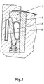
- the Figure 1 shows a sectional side view of a clamping device in the changing position.
- the clamping device 2 is arranged in a recess provided, the cylinder channel.
- the upper clamping strip 3 of the clamping device 2 is fixed, has an approximately C-shaped design and is firmly connected to the plate cylinder 1 .
- the upper terminal strip 3 has a clamping surface 3.1 , against which the pressure plate 11 to be clamped is clamped or fixed with the lower terminal strip or clamping rail 5 .
- a bearing point 5.1 is provided in the lower terminal strip or clamping rail 5 on its side facing the interior of the plate cylinder 1 , the bearing point 5.1 slidingly receiving the upper end of the rigid element 6 .
- the clamping strip 3, cover strip 10 and clamping strip or clamping rail 5 extend over the entire width of the plate cylinder 1.
- the lower end of the rigid element 6 is movably supported by the bearing point 6.1 on the pretensioning device 4 , the spring elements 7 being arranged at a distance from one another are.
- the gap height and the force to be applied can be adjusted by means of a pretensioning device 4 .
- clamping strip 3, cover strip and / or clamping strip or clamping rail 5, these elements are arranged in several parts over the length of the plate cylinder 1 .
- several rigid elements 6 are arranged at equal intervals as possible.
- the change position is achieved by corresponding switching of the adjusting elements, here for example by means of the pneumatic pressure medium expandable pressure hose 8 , in which the pressure hose 8 is pressurized, the pressure hose 9 remains unfilled and thus deflects the rigid element 6 to the left, causing the pressure hose to move to the lower Terminal strip or clamping rail 5 acting force is withdrawn.
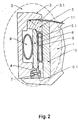
- the Figure 2 shows the clamping device 2 in the clamping position in a sectional side view.
- the clamping position is achieved in that the pressure hose 9 is pressurized, the pressure hose 8 remains unfilled.
- the rigid element 6 pushes the lower terminal strip or clamping rail 5, after the bearing point 5.1 is reached, upwards. So that the pressure plate 11 located in the previous distance is now on the Clamping surface 3.1 of the upper terminal strip 3 pressed and securely fixed and securely clamped between the upper surface of the clamping rail 5 and the clamping surface 3.1 .
- an adjustable pressure piece 4 or spring element 7, which together form the pretensioning device By using an adjustable pressure piece 4 or spring element 7, which together form the pretensioning device, it is possible to securely clamp plate-shaped objects on rotationally symmetrical bodies, plate thicknesses of 0.1 to 1 mm, for example, can be clamped with a single clamping device.
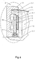
- the Figures 3 and 4 show in detail the bearing point 5.1 of the upper end section 13 of the rigid element 6 on the lower terminal strip (clamping rail) 5.
- the lower side of the terminal strip (clamping rail) 5 has a curved guide 12 on which the upper end section 13 of the rigid element 6 during the switching process from the clamping position to the changing position and vice versa.
- the Figure 3 shows the upper end portion 13 of the rigid element 6, which is rounded semicircular, in connection with the curved guide 12 of the lower clamping strip (clamping rail) 5, while the Figure 4 shows another embodiment.
- the upper end section 13 of the rigid element 6 is rounded in a semicircle and has roller inserts 14 spaced apart from one another.
- the Figure 5 shows a sectional side view of a further embodiment of the clamping device in the change position.
- the clamping device 3 is arranged in a recess provided, the cylinder channel 2 .
- the upper clamping bar 3 of the clamping or tensioning device 2 is designed to be stationary and is firmly connected to the plate cylinder 1 .
- the upper terminal strip 3 has a clamping surface 3.1 , against which the pressure plate to be clamped is clamped or fixed with the lower terminal strip or clamping rail 5 .
- a bearing point 5.1 is provided on its side facing the interior of the plate cylinder 1 , the bearing point 5.1 the upper end portion 13 of the rigid element 6 slidably receives.
- the clamping strip 3, cover strip 10 and clamping strip or clamping rail 5 extend over the entire width of the plate cylinder 1.
- the lower end of the rigid element 6 is movable by the bearing point 6.1 on the pretensioning device, which is formed from pressure pieces 4 and spring elements 7 supported.
- the spring elements 7 are arranged at a distance from one another. The gap height and the force to be applied can be adjusted by means of a pretensioning device.
- the change position is achieved by corresponding switching of the adjusting elements, here for example by means of a pneumatic pressure medium expandable pressure hose 8 in which the pressure hose 8 is pressurized, the compression spring 15 is loaded and the rigid element 6 deflects to the left, whereby the pressure on the lower terminal strip or clamping rail 5 acting force is withdrawn.
- the Figure 6 shows a sectional side view of a further embodiment of the clamping device 2 in the clamping position.
- the clamping position is achieved in that the pressure hose 8 is relaxed (emptied) and the compression spring 15 is relaxed.
- the rigid element 6 pushes the lower terminal strip or clamping rail 5, after the bearing point 5.1 is reached, upwards.
- the pressure plate 11 located at the previous distance is now pressed against the clamping surface 3.1 of the upper terminal strip 3 and securely fixed and securely clamped between the upper surface of the clamping rail 5 and the clamping surface 3.1 .
- an adjustable pressure piece 4 or spring element 7, which form the pretensioning device By using an adjustable pressure piece 4 or spring element 7, which form the pretensioning device, it is possible to securely clamp plate-shaped objects on rotationally symmetrical bodies, plate thicknesses of 0.1 to 1 mm, for example, can be clamped with a single clamping device.
Landscapes
- Supply, Installation And Extraction Of Printed Sheets Or Plates (AREA)
Priority Applications (1)
| Application Number | Priority Date | Filing Date | Title |
|---|---|---|---|
| PL19000088T PL3536503T3 (pl) | 2018-03-09 | 2019-02-15 | Urządzenie zaciskowe do mocowania płyt drukarskich na cylindrze płytowym maszyny drukarskiej |
Applications Claiming Priority (1)
| Application Number | Priority Date | Filing Date | Title |
|---|---|---|---|
| DE202018001278.5U DE202018001278U1 (de) | 2018-03-09 | 2018-03-09 | Klemmvorrichtung zur Befestigung plattenförmiger Gegenstände in rotationssymmetrischen Körpern |
Publications (2)
| Publication Number | Publication Date |
|---|---|
| EP3536503A1 EP3536503A1 (de) | 2019-09-11 |
| EP3536503B1 true EP3536503B1 (de) | 2020-12-16 |
Family
ID=65493784
Family Applications (1)
| Application Number | Title | Priority Date | Filing Date |
|---|---|---|---|
| EP19000088.5A Not-in-force EP3536503B1 (de) | 2018-03-09 | 2019-02-15 | Klemmvorrichtung zur befestigung von druckplatten auf einem plattenzylinder einer druckmaschine |
Country Status (6)
| Country | Link |
|---|---|
| EP (1) | EP3536503B1 (pl) |
| DE (1) | DE202018001278U1 (pl) |
| DK (1) | DK3536503T3 (pl) |
| ES (1) | ES2864218T3 (pl) |
| HU (1) | HUE054070T2 (pl) |
| PL (1) | PL3536503T3 (pl) |
Families Citing this family (1)
| Publication number | Priority date | Publication date | Assignee | Title |
|---|---|---|---|---|
| DE102024132648A1 (de) * | 2024-11-08 | 2026-05-13 | Koenig & Bauer Ag | Plattenzylinder mit Spannvorrichtung und vorderem Öffnungsantrieb und ein Verfahren zum Betreiben einer Druckmaschine |
Family Cites Families (5)
| Publication number | Priority date | Publication date | Assignee | Title |
|---|---|---|---|---|
| DE3422530C1 (de) | 1984-06-16 | 1985-10-10 | Janko 6052 Mühlheim Despot | Vorrichtung zum Befestigen einer biegsamen Druckplatte |
| DE29506864U1 (de) | 1995-04-24 | 1995-06-22 | Kba-Planeta Ag, 01445 Radebeul | Klemmvorrichtung |
| DE10223894B4 (de) * | 2002-05-29 | 2004-06-24 | Koenig & Bauer Ag | Plattenklemmvorrichtung |
| DE10223895C1 (de) * | 2002-05-29 | 2003-12-11 | Koenig & Bauer Ag | Plattenklemmvorrichtung |
| DE102007002785B4 (de) * | 2007-01-18 | 2013-11-14 | Herold Maschinenbau Gmbh | Rotationssymmetrischer Körper mit einer Spannvorrichtung zur Befestigung von plattenförmigen Gegenständen |
-
2018
- 2018-03-09 DE DE202018001278.5U patent/DE202018001278U1/de not_active Expired - Lifetime
-
2019
- 2019-02-15 EP EP19000088.5A patent/EP3536503B1/de not_active Not-in-force
- 2019-02-15 DK DK19000088.5T patent/DK3536503T3/da active
- 2019-02-15 ES ES19000088T patent/ES2864218T3/es active Active
- 2019-02-15 PL PL19000088T patent/PL3536503T3/pl unknown
- 2019-02-15 HU HUE19000088A patent/HUE054070T2/hu unknown
Non-Patent Citations (1)
| Title |
|---|
| None * |
Also Published As
| Publication number | Publication date |
|---|---|
| PL3536503T3 (pl) | 2021-07-05 |
| HUE054070T2 (hu) | 2021-08-30 |
| EP3536503A1 (de) | 2019-09-11 |
| ES2864218T3 (es) | 2021-10-13 |
| DK3536503T3 (da) | 2021-03-22 |
| DE202018001278U1 (de) | 2019-06-12 |
Similar Documents
| Publication | Publication Date | Title |
|---|---|---|
| EP2315877B1 (de) | Schweissaggregat zum verschweissen von schienen eines gleises | |
| EP3569354B1 (de) | Vorrichtung zur fixierung von werkstücken und bearbeitungsanlage. | |
| DE102007002785B4 (de) | Rotationssymmetrischer Körper mit einer Spannvorrichtung zur Befestigung von plattenförmigen Gegenständen | |
| EP3093102A1 (de) | Lünette | |
| DE102007012316A1 (de) | Verfahren und Anbiegepresse zum Anbiegen der Randstreifen eines zu einem Schlitzrohr zu formenden Bleches | |
| DE20002915U1 (de) | Brems- und/oder Klemmvorrichtung für Führungen | |
| EP2885108B1 (de) | Hubvorrichtung mit kniehebelgetriebe | |
| EP2147801B1 (de) | Bindevorrichtung | |
| DE10223894B4 (de) | Plattenklemmvorrichtung | |
| DE10009667B4 (de) | Spanneinrichtung zum Aufspannen von Druckformen | |
| EP0771597B2 (de) | Vorrichtung zum Biegen oder Krümmen von Hohlprofilleisten | |
| EP3536503A1 (de) | Klemmvorrichtung (spannvorrichtung) zur befestigung plattenförmiger gegenstände auf rotationssymmetrischen körpern | |
| DE10024329A1 (de) | Verfahren und Vorrichtungen zum Andrücken eines Aufzuges auf einen Zylinder | |
| DE202018001070U1 (de) | Klemmvorrichtung (Spannvorrichtung) zur Befestigung plattenförmiger Gegenstände auf rotationssymmetrischen Körpern | |
| EP0695591B1 (de) | Vorrichtung zum Biegen von Hohlprofilen mit nicht allseitig geschlossenen Profilquerschnitten | |
| DE2744529C3 (de) | Schweißmaschine zum elektrischen Widerstands-Stumpfschweißen | |
| EP3549770A1 (de) | Klemmvorrichtung (spannvorrichtung) zur befestigung plattenförmiger gegenstände in rotationssymmetrischen körpern | |
| EP3546215B1 (de) | Klemmvorrichtung zur befestigung von druckplatten auf einem plattenzylinder | |
| EP1767361B1 (de) | Biegemaschine mit beweglicher Druckleiste | |
| DE102014104641A1 (de) | Schweißelektrodeneinheit | |
| EP2145728B1 (de) | Vorschubvorrichtung für plattenförmige Werkstücke | |
| DE202018001071U1 (de) | Klemmvorrichtung (Spannvorrichtung) zur Befestigung plattenförmiger Gegenstände auf rotationssymmetrischen Körpern | |
| EP0481326B1 (de) | Spannvorrichtung | |
| DE10306161B4 (de) | Einrichtung zum Innenhochdruckumformen von Werkstücken | |
| EP0760439B1 (de) | Vorrichtung zum Befestigen eines Verbindungselementes am Gurtende eines Förderbandes |
Legal Events
| Date | Code | Title | Description |
|---|---|---|---|
| PUAI | Public reference made under article 153(3) epc to a published international application that has entered the european phase |
Free format text: ORIGINAL CODE: 0009012 |
|
| STAA | Information on the status of an ep patent application or granted ep patent |
Free format text: STATUS: THE APPLICATION HAS BEEN PUBLISHED |
|
| AK | Designated contracting states |
Kind code of ref document: A1 Designated state(s): AL AT BE BG CH CY CZ DE DK EE ES FI FR GB GR HR HU IE IS IT LI LT LU LV MC MK MT NL NO PL PT RO RS SE SI SK SM TR |
|
| AX | Request for extension of the european patent |
Extension state: BA ME |
|
| STAA | Information on the status of an ep patent application or granted ep patent |
Free format text: STATUS: REQUEST FOR EXAMINATION WAS MADE |
|
| 17P | Request for examination filed |
Effective date: 20200204 |
|
| GRAP | Despatch of communication of intention to grant a patent |
Free format text: ORIGINAL CODE: EPIDOSNIGR1 |
|
| STAA | Information on the status of an ep patent application or granted ep patent |
Free format text: STATUS: GRANT OF PATENT IS INTENDED |
|
| INTG | Intention to grant announced |
Effective date: 20201007 |
|
| GRAS | Grant fee paid |
Free format text: ORIGINAL CODE: EPIDOSNIGR3 |
|
| GRAA | (expected) grant |
Free format text: ORIGINAL CODE: 0009210 |
|
| STAA | Information on the status of an ep patent application or granted ep patent |
Free format text: STATUS: THE PATENT HAS BEEN GRANTED |
|
| AK | Designated contracting states |
Kind code of ref document: B1 Designated state(s): AL AT BE BG CH CY CZ DE DK EE ES FI FR GB GR HR HU IE IS IT LI LT LU LV MC MK MT NL NO PL PT RO RS SE SI SK SM TR |
|
| REG | Reference to a national code |
Ref country code: GB Ref legal event code: FG4D Free format text: NOT ENGLISH |
|
| REG | Reference to a national code |
Ref country code: IE Ref legal event code: FG4D Free format text: LANGUAGE OF EP DOCUMENT: GERMAN |
|
| REG | Reference to a national code |
Ref country code: DE Ref legal event code: R096 Ref document number: 502019000509 Country of ref document: DE |
|
| REG | Reference to a national code |
Ref country code: AT Ref legal event code: REF Ref document number: 1345227 Country of ref document: AT Kind code of ref document: T Effective date: 20210115 |
|
| REG | Reference to a national code |
Ref country code: DK Ref legal event code: T3 Effective date: 20210316 |
|
| REG | Reference to a national code |
Ref country code: NL Ref legal event code: FP |
|
| PG25 | Lapsed in a contracting state [announced via postgrant information from national office to epo] |
Ref country code: RS Free format text: LAPSE BECAUSE OF FAILURE TO SUBMIT A TRANSLATION OF THE DESCRIPTION OR TO PAY THE FEE WITHIN THE PRESCRIBED TIME-LIMIT Effective date: 20201216 Ref country code: FI Free format text: LAPSE BECAUSE OF FAILURE TO SUBMIT A TRANSLATION OF THE DESCRIPTION OR TO PAY THE FEE WITHIN THE PRESCRIBED TIME-LIMIT Effective date: 20201216 Ref country code: NO Free format text: LAPSE BECAUSE OF FAILURE TO SUBMIT A TRANSLATION OF THE DESCRIPTION OR TO PAY THE FEE WITHIN THE PRESCRIBED TIME-LIMIT Effective date: 20210316 Ref country code: GR Free format text: LAPSE BECAUSE OF FAILURE TO SUBMIT A TRANSLATION OF THE DESCRIPTION OR TO PAY THE FEE WITHIN THE PRESCRIBED TIME-LIMIT Effective date: 20210317 |
|
| PG25 | Lapsed in a contracting state [announced via postgrant information from national office to epo] |
Ref country code: BG Free format text: LAPSE BECAUSE OF FAILURE TO SUBMIT A TRANSLATION OF THE DESCRIPTION OR TO PAY THE FEE WITHIN THE PRESCRIBED TIME-LIMIT Effective date: 20210316 Ref country code: LV Free format text: LAPSE BECAUSE OF FAILURE TO SUBMIT A TRANSLATION OF THE DESCRIPTION OR TO PAY THE FEE WITHIN THE PRESCRIBED TIME-LIMIT Effective date: 20201216 Ref country code: SE Free format text: LAPSE BECAUSE OF FAILURE TO SUBMIT A TRANSLATION OF THE DESCRIPTION OR TO PAY THE FEE WITHIN THE PRESCRIBED TIME-LIMIT Effective date: 20201216 |
|
| PG25 | Lapsed in a contracting state [announced via postgrant information from national office to epo] |
Ref country code: HR Free format text: LAPSE BECAUSE OF FAILURE TO SUBMIT A TRANSLATION OF THE DESCRIPTION OR TO PAY THE FEE WITHIN THE PRESCRIBED TIME-LIMIT Effective date: 20201216 |
|
| REG | Reference to a national code |
Ref country code: LT Ref legal event code: MG9D |
|
| PG25 | Lapsed in a contracting state [announced via postgrant information from national office to epo] |
Ref country code: EE Free format text: LAPSE BECAUSE OF FAILURE TO SUBMIT A TRANSLATION OF THE DESCRIPTION OR TO PAY THE FEE WITHIN THE PRESCRIBED TIME-LIMIT Effective date: 20201216 Ref country code: LT Free format text: LAPSE BECAUSE OF FAILURE TO SUBMIT A TRANSLATION OF THE DESCRIPTION OR TO PAY THE FEE WITHIN THE PRESCRIBED TIME-LIMIT Effective date: 20201216 Ref country code: PT Free format text: LAPSE BECAUSE OF FAILURE TO SUBMIT A TRANSLATION OF THE DESCRIPTION OR TO PAY THE FEE WITHIN THE PRESCRIBED TIME-LIMIT Effective date: 20210416 Ref country code: RO Free format text: LAPSE BECAUSE OF FAILURE TO SUBMIT A TRANSLATION OF THE DESCRIPTION OR TO PAY THE FEE WITHIN THE PRESCRIBED TIME-LIMIT Effective date: 20201216 Ref country code: SM Free format text: LAPSE BECAUSE OF FAILURE TO SUBMIT A TRANSLATION OF THE DESCRIPTION OR TO PAY THE FEE WITHIN THE PRESCRIBED TIME-LIMIT Effective date: 20201216 Ref country code: SK Free format text: LAPSE BECAUSE OF FAILURE TO SUBMIT A TRANSLATION OF THE DESCRIPTION OR TO PAY THE FEE WITHIN THE PRESCRIBED TIME-LIMIT Effective date: 20201216 |
|
| REG | Reference to a national code |
Ref country code: HU Ref legal event code: AG4A Ref document number: E054070 Country of ref document: HU |
|
| REG | Reference to a national code |
Ref country code: DE Ref legal event code: R097 Ref document number: 502019000509 Country of ref document: DE |
|
| PG25 | Lapsed in a contracting state [announced via postgrant information from national office to epo] |
Ref country code: MC Free format text: LAPSE BECAUSE OF FAILURE TO SUBMIT A TRANSLATION OF THE DESCRIPTION OR TO PAY THE FEE WITHIN THE PRESCRIBED TIME-LIMIT Effective date: 20201216 Ref country code: IS Free format text: LAPSE BECAUSE OF FAILURE TO SUBMIT A TRANSLATION OF THE DESCRIPTION OR TO PAY THE FEE WITHIN THE PRESCRIBED TIME-LIMIT Effective date: 20210416 |
|
| REG | Reference to a national code |
Ref country code: ES Ref legal event code: FG2A Ref document number: 2864218 Country of ref document: ES Kind code of ref document: T3 Effective date: 20211013 |
|
| PLBE | No opposition filed within time limit |
Free format text: ORIGINAL CODE: 0009261 |
|
| STAA | Information on the status of an ep patent application or granted ep patent |
Free format text: STATUS: NO OPPOSITION FILED WITHIN TIME LIMIT |
|
| REG | Reference to a national code |
Ref country code: BE Ref legal event code: MM Effective date: 20210228 |
|
| PG25 | Lapsed in a contracting state [announced via postgrant information from national office to epo] |
Ref country code: AL Free format text: LAPSE BECAUSE OF FAILURE TO SUBMIT A TRANSLATION OF THE DESCRIPTION OR TO PAY THE FEE WITHIN THE PRESCRIBED TIME-LIMIT Effective date: 20201216 Ref country code: LU Free format text: LAPSE BECAUSE OF NON-PAYMENT OF DUE FEES Effective date: 20210215 |
|
| 26N | No opposition filed |
Effective date: 20210917 |
|
| PG25 | Lapsed in a contracting state [announced via postgrant information from national office to epo] |
Ref country code: IE Free format text: LAPSE BECAUSE OF NON-PAYMENT OF DUE FEES Effective date: 20210215 |
|
| PG25 | Lapsed in a contracting state [announced via postgrant information from national office to epo] |
Ref country code: SI Free format text: LAPSE BECAUSE OF FAILURE TO SUBMIT A TRANSLATION OF THE DESCRIPTION OR TO PAY THE FEE WITHIN THE PRESCRIBED TIME-LIMIT Effective date: 20201216 |
|
| PGFP | Annual fee paid to national office [announced via postgrant information from national office to epo] |
Ref country code: NL Payment date: 20220216 Year of fee payment: 4 Ref country code: IT Payment date: 20220228 Year of fee payment: 4 |
|
| PG25 | Lapsed in a contracting state [announced via postgrant information from national office to epo] |
Ref country code: BE Free format text: LAPSE BECAUSE OF NON-PAYMENT OF DUE FEES Effective date: 20210228 |
|
| REG | Reference to a national code |
Ref country code: CH Ref legal event code: PL |
|
| PG25 | Lapsed in a contracting state [announced via postgrant information from national office to epo] |
Ref country code: LI Free format text: LAPSE BECAUSE OF NON-PAYMENT OF DUE FEES Effective date: 20220228 Ref country code: CH Free format text: LAPSE BECAUSE OF NON-PAYMENT OF DUE FEES Effective date: 20220228 |
|
| PGFP | Annual fee paid to national office [announced via postgrant information from national office to epo] |
Ref country code: FR Payment date: 20230224 Year of fee payment: 5 Ref country code: ES Payment date: 20230302 Year of fee payment: 5 Ref country code: DK Payment date: 20230124 Year of fee payment: 5 Ref country code: CZ Payment date: 20230210 Year of fee payment: 5 |
|
| PGFP | Annual fee paid to national office [announced via postgrant information from national office to epo] |
Ref country code: HU Payment date: 20230210 Year of fee payment: 5 Ref country code: GB Payment date: 20230330 Year of fee payment: 5 Ref country code: DE Payment date: 20221117 Year of fee payment: 5 |
|
| PG25 | Lapsed in a contracting state [announced via postgrant information from national office to epo] |
Ref country code: CY Free format text: LAPSE BECAUSE OF FAILURE TO SUBMIT A TRANSLATION OF THE DESCRIPTION OR TO PAY THE FEE WITHIN THE PRESCRIBED TIME-LIMIT Effective date: 20201216 |
|
| REG | Reference to a national code |
Ref country code: NL Ref legal event code: MM Effective date: 20230301 |
|
| PG25 | Lapsed in a contracting state [announced via postgrant information from national office to epo] |
Ref country code: NL Free format text: LAPSE BECAUSE OF NON-PAYMENT OF DUE FEES Effective date: 20230301 |
|
| PG25 | Lapsed in a contracting state [announced via postgrant information from national office to epo] |
Ref country code: IT Free format text: LAPSE BECAUSE OF NON-PAYMENT OF DUE FEES Effective date: 20230215 |
|
| PG25 | Lapsed in a contracting state [announced via postgrant information from national office to epo] |
Ref country code: MK Free format text: LAPSE BECAUSE OF FAILURE TO SUBMIT A TRANSLATION OF THE DESCRIPTION OR TO PAY THE FEE WITHIN THE PRESCRIBED TIME-LIMIT Effective date: 20201216 |
|
| PGFP | Annual fee paid to national office [announced via postgrant information from national office to epo] |
Ref country code: PL Payment date: 20230119 Year of fee payment: 5 |
|
| REG | Reference to a national code |
Ref country code: DE Ref legal event code: R119 Ref document number: 502019000509 Country of ref document: DE |
|
| REG | Reference to a national code |
Ref country code: DK Ref legal event code: EBP Effective date: 20240229 |
|
| PG25 | Lapsed in a contracting state [announced via postgrant information from national office to epo] |
Ref country code: MT Free format text: LAPSE BECAUSE OF FAILURE TO SUBMIT A TRANSLATION OF THE DESCRIPTION OR TO PAY THE FEE WITHIN THE PRESCRIBED TIME-LIMIT Effective date: 20201216 |
|
| GBPC | Gb: european patent ceased through non-payment of renewal fee |
Effective date: 20240215 |
|
| PG25 | Lapsed in a contracting state [announced via postgrant information from national office to epo] |
Ref country code: CZ Free format text: LAPSE BECAUSE OF NON-PAYMENT OF DUE FEES Effective date: 20240215 |
|
| PG25 | Lapsed in a contracting state [announced via postgrant information from national office to epo] |
Ref country code: HU Free format text: LAPSE BECAUSE OF NON-PAYMENT OF DUE FEES Effective date: 20240216 |
|
| PG25 | Lapsed in a contracting state [announced via postgrant information from national office to epo] |
Ref country code: HU Free format text: LAPSE BECAUSE OF NON-PAYMENT OF DUE FEES Effective date: 20240216 Ref country code: CZ Free format text: LAPSE BECAUSE OF NON-PAYMENT OF DUE FEES Effective date: 20240215 |
|
| PG25 | Lapsed in a contracting state [announced via postgrant information from national office to epo] |
Ref country code: DE Free format text: LAPSE BECAUSE OF NON-PAYMENT OF DUE FEES Effective date: 20240903 |
|
| PG25 | Lapsed in a contracting state [announced via postgrant information from national office to epo] |
Ref country code: DK Free format text: LAPSE BECAUSE OF NON-PAYMENT OF DUE FEES Effective date: 20240229 |
|
| PG25 | Lapsed in a contracting state [announced via postgrant information from national office to epo] |
Ref country code: GB Free format text: LAPSE BECAUSE OF NON-PAYMENT OF DUE FEES Effective date: 20240215 |
|
| PG25 | Lapsed in a contracting state [announced via postgrant information from national office to epo] |
Ref country code: FR Free format text: LAPSE BECAUSE OF NON-PAYMENT OF DUE FEES Effective date: 20240229 |
|
| PG25 | Lapsed in a contracting state [announced via postgrant information from national office to epo] |
Ref country code: GB Free format text: LAPSE BECAUSE OF NON-PAYMENT OF DUE FEES Effective date: 20240215 Ref country code: FR Free format text: LAPSE BECAUSE OF NON-PAYMENT OF DUE FEES Effective date: 20240229 Ref country code: DK Free format text: LAPSE BECAUSE OF NON-PAYMENT OF DUE FEES Effective date: 20240229 Ref country code: DE Free format text: LAPSE BECAUSE OF NON-PAYMENT OF DUE FEES Effective date: 20240903 |
|
| REG | Reference to a national code |
Ref country code: ES Ref legal event code: FD2A Effective date: 20250331 |
|
| REG | Reference to a national code |
Ref country code: AT Ref legal event code: MM01 Ref document number: 1345227 Country of ref document: AT Kind code of ref document: T Effective date: 20240215 |
|
| PG25 | Lapsed in a contracting state [announced via postgrant information from national office to epo] |
Ref country code: ES Free format text: LAPSE BECAUSE OF NON-PAYMENT OF DUE FEES Effective date: 20240216 |
|
| PG25 | Lapsed in a contracting state [announced via postgrant information from national office to epo] |
Ref country code: AT Free format text: LAPSE BECAUSE OF NON-PAYMENT OF DUE FEES Effective date: 20240215 |
|
| PG25 | Lapsed in a contracting state [announced via postgrant information from national office to epo] |
Ref country code: PL Free format text: LAPSE BECAUSE OF NON-PAYMENT OF DUE FEES Effective date: 20240215 |
|
| PG25 | Lapsed in a contracting state [announced via postgrant information from national office to epo] |
Ref country code: TR Free format text: LAPSE BECAUSE OF FAILURE TO SUBMIT A TRANSLATION OF THE DESCRIPTION OR TO PAY THE FEE WITHIN THE PRESCRIBED TIME-LIMIT Effective date: 20201216 |
|
| PGFP | Annual fee paid to national office [announced via postgrant information from national office to epo] |
Ref country code: AT Payment date: 20260410 Year of fee payment: 5 |