EP3535548B1 - Dispositif de détection, code de position et méthode de détection de position - Google Patents
Dispositif de détection, code de position et méthode de détection de position Download PDFInfo
- Publication number
- EP3535548B1 EP3535548B1 EP17821717.0A EP17821717A EP3535548B1 EP 3535548 B1 EP3535548 B1 EP 3535548B1 EP 17821717 A EP17821717 A EP 17821717A EP 3535548 B1 EP3535548 B1 EP 3535548B1
- Authority
- EP
- European Patent Office
- Prior art keywords
- markings
- row
- column
- code
- rows
- Prior art date
- Legal status (The legal status is an assumption and is not a legal conclusion. Google has not performed a legal analysis and makes no representation as to the accuracy of the status listed.)
- Active
Links
Images


Classifications
-
- G—PHYSICS
- G01—MEASURING; TESTING
- G01D—MEASURING NOT SPECIALLY ADAPTED FOR A SPECIFIC VARIABLE; ARRANGEMENTS FOR MEASURING TWO OR MORE VARIABLES NOT COVERED IN A SINGLE OTHER SUBCLASS; TARIFF METERING APPARATUS; MEASURING OR TESTING NOT OTHERWISE PROVIDED FOR
- G01D5/00—Mechanical means for transferring the output of a sensing member; Means for converting the output of a sensing member to another variable where the form or nature of the sensing member does not constrain the means for converting; Transducers not specially adapted for a specific variable
- G01D5/26—Mechanical means for transferring the output of a sensing member; Means for converting the output of a sensing member to another variable where the form or nature of the sensing member does not constrain the means for converting; Transducers not specially adapted for a specific variable characterised by optical transfer means, i.e. using infrared, visible, or ultraviolet light
- G01D5/32—Mechanical means for transferring the output of a sensing member; Means for converting the output of a sensing member to another variable where the form or nature of the sensing member does not constrain the means for converting; Transducers not specially adapted for a specific variable characterised by optical transfer means, i.e. using infrared, visible, or ultraviolet light with attenuation or whole or partial obturation of beams of light
- G01D5/34—Mechanical means for transferring the output of a sensing member; Means for converting the output of a sensing member to another variable where the form or nature of the sensing member does not constrain the means for converting; Transducers not specially adapted for a specific variable characterised by optical transfer means, i.e. using infrared, visible, or ultraviolet light with attenuation or whole or partial obturation of beams of light the beams of light being detected by photocells
- G01D5/347—Mechanical means for transferring the output of a sensing member; Means for converting the output of a sensing member to another variable where the form or nature of the sensing member does not constrain the means for converting; Transducers not specially adapted for a specific variable characterised by optical transfer means, i.e. using infrared, visible, or ultraviolet light with attenuation or whole or partial obturation of beams of light the beams of light being detected by photocells using displacement encoding scales
- G01D5/34776—Absolute encoders with analogue or digital scales
Definitions
- the invention relates to a positioning code and to a position detecting method for high accuracy position detecting applications.
- Pixel-based encoders offer several advantages over traditional optical encoders, such as higher resolution, higher accuracy, much more robustness, higher flexibility and the possibility of multi-dimensional 2D, 3D,... 6D position measurements just to mention a few. While traditional optical encoders use only a few photoreceptors, pixel-based encoders use tens- or hundreds of thousands of photoreceptors (pixels). The large number of pixels allow pixel-based encoders to go beyond the fundamental limits of traditional encoders in terms of most important encoder specifications.
- pixels may have any type of sensor elements (e.g. photon, electron, radiation, or e-beam sensor elements).
- sensor elements e.g. photon, electron, radiation, or e-beam sensor elements.
- Prior art solutions use pixel-based encoders with two-dimensional positioning codes consisting of a two-dimensional regular (or in other word repetitive) pattern and an absolute positioning code which is interlaced with the two-dimensional regular pattern.
- the absolute positioning code can be read for establishing the absolute code of the current position, while the two-dimensional regular pattern serves for enhancing resolution; the position of the two-dimensional regular pattern with respect to the pixel-arrangement of the encoder can be determined and thus the resolution highly enhanced.
- the combination of two, i.e. an absolute code and a code pattern position with respect to the two-dimensional arrangement of the pixels can be used together to measure precisely the absolute position of the positioning code with respect to the detector device.
- the major challenge of pixel-based encoders with respect to traditional encoders is the speed, or latency of the encoder, because the computing- and power needs to process a large number of pixels are orders of magnitudes beyond that of conventional encoders. Also the attainable frame-rates of conventional image sensors are orders of magnitude below than needed for high-speed optical encoder applications.
- the reading of the absolute code and the detecting of the position of the pattern with respect to the pixel arrangement necessitates combined and complicated reading steps.
- US 7,193,197 B2 discloses a detection device enabling a combined reading of pixels, but this device enables accessing row-sums and column-sums of pixels only, and information carried by individual pixels is lost, thereby it is not suitable to read the absolute code. Namely, all pixels in a row are connected by one wiring and all pixels in a column are connected by one wiring. Connected/wired pixels become 'one long pixel', one electrical node, and the photo-current of all connected/wired pixels is summed up. Wiring makes it impossible to access/read-out individual pixels. Image variations along the wirings are not detectable. In an MxN wired pixel array there are only M+N effective pixels: M long pixels in one dimension and N long pixels in the other dimension.
- the invention provides a method to read out the pixel array at the highest possible speed, by introducing simultaneous row-wise and column-wise parallelism, to calculate row-sums (or row-mean), column-sums (or column-mean) and to facilitate fast decoding of the absolute code.
- the novel image sensor in which row-wise and column-wise operations and readout are made in parallel, is a concept which allows fast-enough image readout and processing for high-speed multidimensional encoders.
- the inventive positioning code is quasi-periodic, and enables to read the absolute code information, and at the same time to enhance resolution by enabling the precise measurement of the position of the pattern with respect to the pixel arrangement of the detector device applied.
- the 2D position (or phase, in case of a periodic pattern) of the code pattern can be measured based on the sum (or mean) of the column-wise pixel intensities and on the sum (or mean) of the row-wise pixel intensities.
- Absolute positioning code information can be obtained by decoding the code, which is encoded either in the shape parameters of the markings (e.g. horizontal, vertical or diagonal marking orientations, marking widths, marking heights, or any other detectable parameters) and/or in the sizes of the spacings between the markings.
- Preferred embodiments enable to generate the row-sum and the column-sum in one step, locating the rows and columns of the markings in the pattern at the same time, and to read the markings in a quick way in the located rows and columns.
- a 2D code according to e.g. Fig. 12 , 16 or 17 can be provided for covering the surface of the Earth with 1mm period markings.
- a 9x9 period window (9mm x 9mm) of such code contains always a unique binary pattern anywhere on the surface of the Earth. By reading this 9x9 bit code the absolute position on Earth can be determined with a 1 mm resolution. Measuring the precise pattern position within the window sub-micrometer resolution can be achieved for the absolute position measurement.
- the invention can be used with a detector device that aims at maximum speed combined with maximum flexibility for reading a quasi-periodic absolute code pattern.
- Quasi-periodic means that the centre of gravity of the markings of the pattern are positioned on a grid, wherein the spacings between the lines defined by the centres of gravity are not necessarily equal.
- rows and columns describe two orthogonal directions of an arrangement. It is conceivable that the row and column denominations can be exchanged with each other depending on the actual point of view, so those are non-limiting expressions merely denominating the two orthogonal directions of the arrangement.
- FIG. 1 A general schematic structure of an applicable detector device is shown in Fig. 1 .
- the detector device has photosensitive or other type of pixels 10, 20 in a two-dimensional arrangement, the arrangement having a row direction and a column direction along which the pixels 10, 20 are aligned in rows and columns.
- each of the pixels 10, 20 comprises a sensor element 30 and an output 31 for outputting an electric signal corresponding to an intensity of radiation incident on the sensor element 30.
- the radiation can be e.g. light.
- the electric signal can be e.g. current, or the pixels may output asynchronous pulses rather than currents. In the latter case pulses outputted by the pixels 10, 20 are summed up and transmitted for processing.
- each of the pixels 10, 20 comprises a readout selection input 33 by means of which the pixel 10, 20 can be selected for outputting.
- the detector device comprises
- the analogue-to-digital converters 13, 23 serve for providing a digital signal for further processing.
- the input of these elements are the electric signals on the row readout wirings 11 and column readout wirings 21.
- the electric signals can be preferably currents, but voltages, pulses or any combination of these are also conceivable.
- the analogue-to-digital converters 13, 23 can have a form of counters providing the digital sum of the arriving pulses.
- the detector device Advantages of the detector device are that maximum readout speed can be combined with maximum flexibility. By enabling to select any set of rows/columns within the range of 1 and all rows/columns, simultaneous row- and column-parallel readout of any pixel up to all pixels is possible, so pattern position/absolute code can be read at a high-speed with the same detector device.
- Column and row pixels can be grouped from 1 to all.
- selecting a group of 1 row or 1 column all individual pixels are read out in N steps in a 2xNxN pixel array.
- Column-parallel read-out and row-parallel read-out are carried out simultaneously.
- T is the pattern period in pixels
- an ideal high-speed, n-step read-out of N 2 bit absolute code is possible.
- the sum of half columns and sum of half rows can be read out in 2 steps, which is ideal to measure image rotation in addition to the 2D position, as detailed later.
- selecting a group of N i.e. all rows and columns, ideal highest-speed, 1 step readout of column-sums and row-sums for 2D position is enabled.
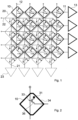
- the inventive pixel layout allows to interlace the row pixels 10 and the column pixels 20 in a single array allowing simultaneous row-wise and column-wise operations in parallel.
- An m x n pixel array, i.e. n pixel columns are connected to the n column-parallel analogue-to-digital converters (ADCs) 23 (thin lines).
- ADCs analogue-to-digital converters
- another m x n pixel array i.e. m pixel rows are connected to the m row-parallel ADCs 13 (thick lines).
- the two-dimensional arrangement of the pixels has two diagonal directions, intersecting the row direction, the column direction and each other, along which the pixels are diagonally aligned, and along which the row pixels 10 and column pixels 20 are alternatingly arranged.
- the pixels have a rhomboid-like shape, the 34 sides of which are in parallel with the diagonal directions, wherein the pixels are arranged with a spacing smaller than the length of the side 34 of the rhomboid-like shape.
- a large effective surface can be ensured for the detector device, together with an interlaced "view" of the same area by the row and column pixels 10, 20.
- pixels are to be read more than one times.
- the 2D position of the pattern can be measured by reading in one step all rows and columns, and subsequently the absolute code can be read by targeted binning of pixel-groups.
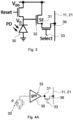
- the pixels further comprise a non-destructive readout circuit 32 between the sensor element 30 and the output 31.
- the non-destructive readout circuit 32 preferably comprises a transconductance unit 35.
- the readout selection input 33 is preferably a gate terminal of a MOSFET 36 constituting a select switch, wherein the output 31 of the pixel is connected to the source of the MOSFET and the drain of the MOSFET is connected to the respective row readout wiring 11 or column readout wiring 21.
- Fig. 4A depicts the inherent capacitance of the sensor element 30, being typically a photodiode, and the general transconductance unit 35.
- Fig. 4B is the symbolic representation of the transconductance unit 35, while Fig. 4C is an example of a two-CMOS transistor transconductance unit.
- each pixel may be a row pixel 10 and a column pixel 20 at the same time, e.g. like a conventional pixel matrix, in which case each pixel comprise two readout selection inputs 33 and two outputs 31 for enabling both row-wise and column-wise readout.
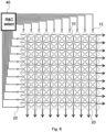
- the column and row selecting device can be a programmable address generator and sequencer unit 40, which is connected to the column select wirings 12 and to the row select wirings 22, and can be programmed to activate the wirings according to the desired readout.
- nxn n times n
- all possible row select, column select configurations can be performed in each clock cycle using n bit row address and n bit column address.
- columns and rows of code-markings may be located in a first position determining step, and even a rotation-measurement can be carried out, the outcomes of which may influence the subsequent addressing of the column select wirings 12 and to the row select wirings 22. Therefore, the address generator and sequencer unit 40 may receive feedback information from the readout-results, and the addressing may at least partly be based on the feedback information.
- the DA converters are not depicted in this Fig.
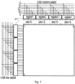
- FIG. 7 A more compact implementation is depicted in Fig. 7 , which uses writeable registers 41 for selecting rows and columns in an arbitrary manner.
- i ceil(log 2 (l)) address bits are needed to address all registers 41.
- three address bits can address eight 4-bit registers, each register 41 can address 16 rows or columns.
- the eight registers 41 can be programmed in eight clock cycles. An ADC conversion takes typically 8-12 clock cycles.
- the new row / column select vectors can be written to the registers 41.
- the programing of the registers 41 may at least partly be based on a feedback information from the readout-results.
- Fig. 8 depicts some subsequent processing elements and possibilities, mainly for the case if no non-destructive readout is possible.
- the row-sum - being a row-sum vector 15 - are preferably generated in a single step, together with the column-sum - being a column-sum vector 25.
- These vectors can be used for measuring the position of the pattern with respect to the pixel arrangement (or in other words with respect to the corresponding detector device), and also for locating rows and columns of markings for targeted and high-speed readout of the absolute code.
- the summing circuits 14 and 24 depict the summing functionality in case all pixels can be read only once.
- mxn pixel memories 16, 26 can be filled in n (n > m) steps, which can be used to detect absolute code or other information.
- the pixel memories 16, 26 contain redundant information, so their content can be used to verification purposes as well by a 42 processing unit.
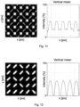
- Fig. 9 depicts the general positioning code structure of prior art solutions.
- pixel-based encoders are used with a two-dimensional positioning code consisting of a two-dimensional regular (repetitive) pattern, being a periodic set of squares in the depicted example, and an absolute code, being a set of diagonal sections in the example, which is interlaced with two-dimensional regular pattern.
- the absolute code is coded by the diagonal orientations of the sections, and can be read for establishing the absolute code, while the two-dimensional regular pattern serves for enhancing resolution.
- the position of the two-dimensional regular pattern with respect to the pixel-arrangement of the encoder can be determined and thus the resolution highly enhanced.
- the prior art positioning code thus enables both high-spatial-resolution, and absolute measurement.
- An idea of the invention is to eliminate the two-dimensional regular pattern, and to use the absolute code pattern also for determining the position of the two-dimensional regular pattern with respect to the pixel-arrangement of the encoder.
- the term 'positioning code' and 'markings' are used in the sense that those are the code and its markings imaged onto the surface of the pixel arrangement of a detector device.
- the code can be fixed to a suitable element of the position determining application, and the imaging can be effected by any suitable means. Markings have a different optical and/or physical property than their background.
- Fig. 10 depicts an example of an inventive positioning code for use with a detector device having pixels 10, 20 in a two-dimensional arrangement, the pixel arrangement having a row direction and a column direction along which the pixels 10, 20 are aligned in rows and columns.
- the code consists of markings 50 in an arrangement having a row direction and a column direction along which the markings 50 are arranged in spaced rows and/or spaced columns.
- markings aligned along two orthogonal logarithmic spirals or other orthogonal curves are also considered to be arranged along a row direction and a column direction; these embodiments are especially advantageous if the code area has a large radial extent.
- the spacings 60 are marking-free, and the absolute positioning code is coded by the shape parameters of the markings 50 and/or by the distances determined by the spacings 60.
- the term 'shape parameters of the markings' covers any visual feature of the markings that can be used for the coding purpose, e.g. different dimensional parameters, orientations, geometry, shape-features or shapes can be used for coding.
- Figs. 11 and 12 show the advantages of the inventive positioning code with respect to the prior art code. It is conceivable from the diagrams of the vertical mean values of the pixels that 2x better S/N (signal-to-noise) ratio can be achieved by the inventive code pattern, as the 'contrast' is higher by eliminating the periodic pattern. The quality of the summing (averaging) is better for the inventive pattern, because
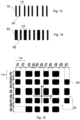
- Figs. 13 to 17 depict preferred, non-limiting examples of markings that can be used in the inventive positioning code. Of course, other suitable marking can also be applied.
- Fig. 13 shows a one dimensional PPM (pulse position modulation) code, wherein the shapes of the markings 51 are identical and the absolute positioning code is coded by the distances determined by the spacings 61.
- Fig. 14 shows a one dimensional PWM (pulse width modulation) code, wherein the spacings 62 determine identical distances and the absolute positioning code is coded by the widths of the markings 52.
- the absolute positioning code is coded by the shape parameters of the markings 52, namely by their widths.
- one period encodes one bit, so N periods encode N bits in the array, enabling to encode 2 N absolute positions.
- Fig. 15 shows a two-dimensional code comprising markings 53 positioned along two orthogonal X and Y dimensions of a code coordinate system.
- the X extensions and the X positions of all markings 53 in a column are equal, and the Y extensions and the Y positions of all markings 53 in a row are equal.
- the absolute positioning code is coded by d ij distances in the two orthogonal X and Y dimensions determined by the extensions of the markings 53 and by the spacings 63 between the markings 53.
- this code pattern being a two-dimensional PPWM (pulse position and width modulation) code one column-period encodes one bit and one row-period encodes one bit.
- 2N periods encode 2N bits in the array, enabling to encode 2 2N absolute positions.
- the markings 53 can have any suitable geometry (e.g. rectangle, triangle, pentagon, hexagon, octagon, etc., circle, ellipse, star, random shape, etc.).
- the code patterns of Figs. 13 to 15 have the advantage that the readout of the absolute code and that of the position of the pattern with respect to the pixel arrangement - by reading e.g. with a detector device discussed above - can be carried out in a single step, so no multiple readout of pixels is necessary and the non-destructive circuits are not necessary in the pixels. Fig.
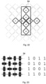
- FIG. 16 shows a two-dimensional code comprising markings 54 having the same shape and having spacings 64 therebetween, the markings are elongated and have a larger longitudinal size L than their crosswise size W, their crosswise size W is larger than the row-parallel and column-parallel dimensions of a pixel 10, 20.
- the absolute positioning code is coded by the row-parallel or column-parallel orientations of the markings 54, the orientation is thus being the shape parameter used for coding purposes.
- one marking 54 in a row-period encodes one bit
- one marking 54 in a column-period encodes one bit, so N 2 periods encode N 2 bits in the array, enabling to encode 2 N ⁇ N absolute positions.
- Fig. 16 also shows the coded bit values of the exemplary code pattern.
- Fig. 17 shows a code pattern similar to that of Fig. 16 , comprising markings 54 that may have two additional orientations, namely any of the two diagonal orientations.
- Fig. 18 shows the first and the k th steps of reading out all pixels of a pixel arrangement of a detector device.
- the detector device has pixels 10, 20 in a two-dimensional arrangement, the arrangement having a row direction and a column direction along which the pixels 10, 20 are aligned in rows and columns.
- the detector device can be that discussed above, but also conventional detector devices having a suitable pixel-arrangement can be used. In the latter case, the row- and column-parallel readout is not hardware-supported, but can be carried out by a computer program on a pixel memory in which all pixel values are read in a conventional way. Accordingly, the inventive method is suitable for conventional detector devices as well.
- a code pattern consisting of markings 54 is used, the markings 54 being in an arrangement having a row direction and a column direction along which the markings 54 are arranged in marking rows and/or marking columns, wherein the row and column directions of the marking arrangement are aligned with the row and column directions of the pixel arrangement.
- the term 'aligned' in this context means that the row and column directions of the marking arrangement coincide with the row and column directions of the pixel arrangement or are slightly rotated with respect to each other to an extent still enabling the detection functionalities.
- the inventive method serves both for detecting a code pattern position with respect to the two-dimensional arrangement of the pixels 10, 20, and an absolute code coded by the code pattern.
- the markings 54 are arranged in the code pattern in spaced rows and/or spaced columns, wherein the spacings 64 between the rows and/or columns are marking-free, and wherein an absolute positioning code is coded by the shape parameters - in the depicted case the orientations - of the markings 54.
- absolute positioning code can also be coded additionally or only by the distances determined by the spacings 64.
- individual pixels can be read by selecting the first row of column pixels 20 and generating the corresponding column-sum vector 25, and by selecting the first column of row pixels 10 and generating the corresponding row-sum vector 15. Values of individual pixels can be found in the vector values. If carried out with an above discussed detector device, the two readings in the first column of the Fig. can be carried out simultaneously, in step 1. In step k, the k th row of column pixels and the k th column of row pixels are selected for readout. In n steps n column pixel vectors and n row pixel vectors, altogether 2 x n x n pixel matrix values can be obtained.
- the code pattern position is detected by generating a column-sum vector 25 and a row-sum vector 15 of the pixel values, and on the basis of the values of the column sum vector 25 and the row-sum vector 15, the positions of the marking columns and marking rows with respect to the two-dimensional arrangement of the pixels 10, 20 are detected. These positions may be defined as the positions of the centre lines 70 of the marking columns and marking rows. These positions constitute the code pattern position.
- the code pattern position with respect to the two-dimensional arrangement of the pixels can also be characterized with a phase value (calculated with respect to the pixel arrangement), being in one-to-one relationship with the marking row and column (or their centre lines 70) positions. Accordingly, the term 'positions of marking rows and columns' is considered in this context to be equivalent with the corresponding phase value.
- the positions of the of marking rows and columns, preferably those of their centre lines 70, can be calculated by means of any know techniques from the values of the vectors.
- the row-sum vector 15 is generated by selecting all columns of the row pixels 10 for row-parallel readout
- the column-sum vector 25 is generated by selecting all rows of column pixels 20 for column-parallel readout.
- the absolute code is decoded by reading the code pattern.
- the row-sum vector 15 and the column-sum vector 25 generated by selecting all rows/columns is suitable for reading, decoding the absolute code.
- the rows of markings 54 and the columns of markings 54 are located on the basis of the values of the row-sum vector 15 and the column-sum vector 25 generated.
- the term 'locating' means that information is available in the vectors relating to the positions and dimensions of the marking rows and columns, which can be effectively used to maximum speed, targeted reading of the individual markings. This location information, combined with a priori knowledge of the positioning code pattern markings, can be used for reading the absolute code.
- absolute code decoding is carried out by
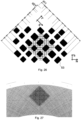
- the above discussed detector device enables that at least one row of markings 54 and one column of markings 54 are read simultaneously, as depicted in Fig. 20 .
- the columns/rows are read in pairs, resulting a considerably speedup of detecting.
- the initial 2D position measurement yields the position and location of marking columns and marking rows.
- a row of column pixels 20 and a column of row pixels 10 are selected in such a way that those sample the upper half (or equivalently the lower half) of the marking row and the marking column respectively. This way pixel activity is asymmetric with respect to the centre line 70 of the marking rows and centre line 70 of marking columns, respectively.
- the images show examples of the code reading.
- the selected row of column pixels 20 results asymmetric pixel activity, for bit 1,1 (upper left marking 54, logical 1 value) the activity is higher on the right side of the centre line 70, while for bit 2,1 (lower left marking 54, logical 0 value) the activity is larger on the left side on the centre line 70.
- bit 1,1 upper left marking 54, logical 1 value
- bit 2,1 lower left marking 54, logical 0 value
- one row/column can be sampled in two positions symmetrically with respect to the centre lines 70, yielding a more robust differential signal for the bit reading.
- Fig. 21 shows the one-step readout of the position, and the subsequent N steps of the code-reading in the case of another marking orientations.
- N 2 bits of absolute code is read out in N steps.
- N is the number of marking rows and columns. In this example each marking encodes one bit. Codes with two bits per marking are also possible, if the additional diagonal orientations are also used.
- the first step yields the position/location of marking columns and marking rows. In the image only those pixel columns/rows are shown, which are used to determine marking orientation. Other pixel columns/rows may be selected, but are preferably not taken into account. E.g. those column/row ADCs can be disabled or sum values can be ignored by the next processor stage. It is noted again that the read-out of the markings column-wise and row-wise is redundant.
- a positioning code according to Fig. 16 is used, and in the reading steps of the rows and columns of the markings 54, neighbouring column pixel 20 rows having a total height and neighbouring row pixel 10 columns having a total width being closer to the longitudinal size L of the markings 54 than to their crosswise size W are selected for reading.
- the different dimensions of the markings 54 can be detected in a straightforward way.
- vertical cross pixels C1-C4 go through (or as close as possible to) the vertical symmetry axis of markings 54
- horizontal cross pixels R1-R4 go through (or as close as possible to) the horizontal symmetry axis of markings 54.
- bit sign((c1+c2+c3+c4) - (r1+r2+r3+r4)).
- the sum of vertical cross pixels c1-c4 and the sum of horizontal cross pixels r1-r4 are preferably read out in one step, by means of the detector device.
- Fig. 23 shows the set of markings 54 with the targeted readout pixels, and the corresponding bit values.
- a rotation measurement is carried out in the code pattern position measurement step.
- the rotation measurement is used to establish the extent of any rotation of the rows and columns of the markings 53, 54 with respect to the rows and columns of the pixels 10, 20.
- the rotation measurement comprises a first step of selecting for parallel readout a subset of the rows of column pixels 20 and generating a first column-sum vector 25, and simultaneously selecting for parallel readout a subset of the columns of row pixels 10 and generating a first row-sum vector 15, and calculating a first code pattern position on the basis of the first column-sum vector 25 and the first row-sum vector 15.
- a second step follows, selecting for parallel readout another subset of the rows of column pixels 20 and generating a second column-sum vector 25, and simultaneously selecting for parallel readout another subset of the columns of row pixels 10 and generating a second row-sum vector 15, and calculating a second code pattern position on the basis of the second column-sum vector 25 and the second row-sum vector 15.
- the code pattern position is calculated as a function of the first and second code pattern positions obtained in the first and second steps, and the rotation is calculated on the basis of the difference between the first and second code pattern positions, also taking into account the dimensions of the pixel arrangement and the position of rows/cols used in the rotation measurement.
- a preferred embodiment is to use as subsets the half of all rows and columns, and averaging the obtained position values.
- the subsets can be any number between 1 and n. There is no need to have consecutive rows/columns either, e.g. every 2 nd can be taken. The positions of the subsets is taken into account in the calculation of the position.
- image rotation can be also measured very precisely, typically 10 ⁇ rad rotation can be detected with a few mm 2 pixel array.
- the rotation calculated can be used in selecting for readout the one or more column pixel 20 rows for reading the rows of markings 54, and in selecting for readout the one or more row pixel 10 columns for reading the columns of markings 54. Namely, the positions of the target pixel sets can be adjusted according to the rotation measured.
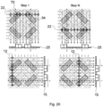
- a rotated image without compensated cross-pixel-positions is shown on the left side of Fig. 25 .
- the sampling of the markings 54 is not in the right position, reading the absolute code is not possible.
- rotated image with compensated cross-pixel-positions is shown on the right side of the Fig..
- the sampling of the markings is in the right position, reading the absolute code is possible.
- the preferred embodiment allows the read-out of rotated image, e.g. due to a mounting tolerance of the sensor, e.g. when the sensor is rotated around its normal.
- the preferred embodiment allows the compensation of not only static image rotation but also dynamic image rotation because rotation angle measurement is intrinsic in the method, e.g. two step readout or row/column pixels with rotation measurement. This allows cross-pixel position adaptation in every measurement cycle according to the measured rotation.
- the absolute code read-out can be performed with the rotation-compensated cross pixel positions. Measurement of rotation at each frame and the compensation of the dynamically changing image rotation are necessary in eccentricity compensation of e.g. in Hollow Shaft Encoders.
- a 2 step readout is used for the row-sums and column-sums for pattern position measurement and rotation measurement, and additional N steps are used for selective reading out of N 2 bits of a 2D absolute code, being in altogether N+2 steps.
- N the number of bits of a 2D absolute code
- additional N steps are used for selective reading out of N 2 bits of a 2D absolute code, being in altogether N+2 steps.
- reading out 8x8 pattern periods encoding 64 bit absolute code is possible in 10 steps.
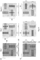
- Fig. 15 shows a case when the X,Y coordinate system of the code is parallel with a Xa, Ya coordinate system of the given application.
- the absolute position of the two dimensions of the application are independent, Xa is encoded only in the rows, Ya is encoded only in the columns.
- a "code-sharing" is provided for PPWM codes, as depicted in Fig. 26 .
- the two-dimensional code pattern and the detector device is rotated by 45° with respect to a coordinate system of a position-determining application, and the two dimensions Xa, Ya of the absolute position in the position-determining application are encoded by both the rows of markings 53 and the columns of markings 53.
- both Xa and Ya dimensions are encoded by the rows and the columns.
- code-sharing has a great significance when the needed scale lengths in the Xa and Ya dimensions are not in the same order of magnitude.
- the needed Xa scale length is 1000 m while Ya scale length is 0.1 m, there are 4 orders of magnitude between them.
- With a pattern period of 1 mm we would need > 20 bit code in dimension Xa, and >7 bit code in dimension Ya.
- the code-sharing we can distribute the 27 bit code between the two scale dimensions and having more balanced reading / decoding with 13 and 14 bit code lengths.
- code sharing is also possible with the positioning codes according to Fig. 12 , 16 and 17 , even without a rotation by 45° with respect to the coordinate system of the application.
- the rotated code can be folded on an arbitrary trajectory needed for the application, e.g. on a circular code-disc.
- the rows and columns may follow straight lines.
- the rows and columns may follow a spiral or logarithmic spiral especially if the code area has a large radial extent.
- Rows and columns of the pattern can be read by the rows and columns of the detector device, the pixel-arrangement of which is also depicted in the Fig. 26 .
- Fig. 27 shows markings arranged along two orthogonal log spirals to obtain for the detector device a locally as close to a square grid as possible on a circular code-disc, e.g. holes in a metal mask or transparent circles on a non-transparent substrate.
Landscapes
- Physics & Mathematics (AREA)
- General Physics & Mathematics (AREA)
- Transmission And Conversion Of Sensor Element Output (AREA)
- Optical Transform (AREA)
- Transforming Light Signals Into Electric Signals (AREA)
- Photometry And Measurement Of Optical Pulse Characteristics (AREA)
Claims (17)
- Code de positionnement pour une utilisation avec un dispositif de détection ayant des pixels (10, 20) dans un agencement bidimensionnel, l'agencement de pixels ayant une direction de rangée et une direction de colonne le long desquelles les pixels (10, 20) sont alignés en rangées et colonnes, le code étant constitué de marquages (50, 51, 52, 53, 54), les marquages (50, 51, 52 53, 54) étant dans un agencement ayant une direction de rangée et une direction de colonne le long desquelles les marquages (50, 51, 52, 53, 54) sont agencés,
caractérisé en ce que les marquages (50, 51, 52, 53, 54) sont des marquages (50, 51, 52, 53, 54) de codage de code de positionnement absolu qui sont agencés en rangées espacées et/ou colonnes espacées, dans lequel les espacements (60, 61, 62, 63, 64) sont dépourvus de marquages, et dans lequel le code de positionnement absolu est codé par des paramètres de forme des marquages (50, 51, 52, 53, 54) et/ou par des distances déterminées par les espacements (60, 61, 62, 63, 64). - Code de positionnement selon la revendication 1, caractérisé en ce qu'il est un code PPM unidimensionnel, dans lequel les formes des marquages (51) sont identiques et le code de positionnement absolu est codé par les distances déterminées par les espacements (61).
- Code de positionnement selon la revendication 1, caractérisé en ce qu'il est un code PWM unidimensionnel, dans lequel les espacements (62) déterminent des distances identiques et le code de positionnement absolu est codé par les largeurs des marquages (52).
- Code de positionnement selon la revendication 1, caractérisé en ce qu'il est un code bidimensionnel comprenant des marquages (53) positionnés le long de deux dimensions orthogonales X et Y d'un système de coordonnées de code, dans lequel- les extensions X et les positions X de tous les marquages (53) dans une colonne sont égales,- les extensions Y et les positions Y de tous les marquages (53) dans une rangée sont égales, et- le code de positionnement absolu est codé par des distances dans les deux dimensions orthogonales X et Y déterminées par les extensions des marquages (53) et par les espacements (63) entre les marquages (53).
- Code de positionnement selon la revendication 1, caractérisé en ce qu'il est un code bidimensionnel comprenant des marquages (54) ayant la même forme, les marquages (54) sont allongés et ont une taille longitudinale (L) plus grande que leur taille dans le sens transversal (W), leur taille dans le sens transversal (W) est plus grande que les dimensions parallèle à la rangée et parallèle à la colonne d'un pixel (10, 20), et le code de positionnement absolu est codé par l'orientation des marquages (54).
- Code de positionnement selon la revendication 5, caractérisé en ce que les marquages (54) peuvent avoir une orientation parallèle à la rangée ou une orientation parallèle à la colonne.
- Code de positionnement selon la revendication 5 ou 6, caractérisé en ce que les marquages (54) peuvent avoir l'une des deux orientations diagonales.
- Procédé de détection de position,utilisant- un dispositif de détection ayant des pixels (10, 20) dans un agencement bidimensionnel, l'agencement ayant une direction de rangée et une direction de colonne le long desquelles les pixels (10, 20) sont alignés en rangées et colonnes, et- un code de positionnement constitué de marquages (50, 51, 52, 53, 54), les marquages (50, 51, 52 53, 54) étant dans un agencement ayant une direction de rangée et une direction de colonne le long desquelles les marquages (50, 51, 52, 53, 54) sont agencés en rangées de marquages et/ou colonnes de marquages, dans lequel les directions de rangée et de colonne de l'agencement de marquages sont alignées avec les directions de rangée et de colonne de l'agencement de pixels,pour détecter la position absolue du code de positionnement par rapport au dispositif de détection, caractérisé en ce que- les marquages (50, 51, 52, 53, 54) sont des marquages (50, 51, 52, 53, 54) de codage de code de positionnement absolu qui sont agencés dans le motif de code en rangées espacées et/ou colonnes espacées, dans lequel les espacements (60, 61, 62, 63, 64) entre les rangées et/ou colonnes sont dépourvus de marquages, et dans lequel un code de positionnement absolu est codé par des paramètres de forme des marquages (50, 51, 52, 53, 54) et/ou par des distances déterminées par les espacements (60, 61, 62, 63, 64),- une position de motif de code est mesurée en générant un vecteur de somme de colonnes (25) et un vecteur de somme de rangées (15) des valeurs de pixels, et sur la base des valeurs du vecteur de somme de colonnes (25) et du vecteur de somme de rangées (15), déterminant les positions des colonnes de marquages et des rangées de marquages par rapport à l'agencement bidimensionnel des pixels (10, 20), lesdites positions constituant la position de motif de code, et- le code de positionnement absolu est décodé par lecture du motif de code.
- Procédé selon la revendication 8, dans lequel pour détecter la position de motif de code, le vecteur de somme de rangées (15) est généré en sélectionnant des colonnes des pixels de rangée (10) pour une lecture parallèle à la rangée, et le vecteur de somme de colonnes (25) est généré en sélectionnant des rangées de pixels de colonne (20) pour une lecture parallèle à la colonne.
- Procédé selon la revendication 9, caractérisé en ce que- avant l'étape de décodage, les rangées de marquages (54) et les colonnes de marquages (54) sont localisées sur la base des valeurs du vecteur de somme de rangées (15) et du vecteur de somme de colonnes (25) générées,et un décodage de code de positionnement absolu est réalisé par- lire les rangées de marquages (54) une par une, dans lequel pour chaque rangée de marquages (54) localisée, une ou plusieurs rangées de pixels de colonne (20) croisant les marquages (54) et étant appropriées pour détecter des informations portées par chacun des marquages (54) sont sélectionnées pour lecture sur la base des sommes de colonnes des rangées de pixels de colonne (20) sélectionnées, et- lire les colonnes de marquages (54) une par une, dans lequel pour chaque colonne de marquages (54) localisée, une ou plusieurs colonnes de pixels de rangée (10) croisant les marquages (54) et étant appropriées pour détecter des informations portées par chacun des marquages (54) sont sélectionnées pour lecture sur la base des sommes de rangées des colonnes de pixels de rangée (10) sélectionnées.
- Procédé selon la revendication 10, caractérisé en ce qu'au moins une rangée de marquages (54) et au moins une colonne de marquages (54) sont lues simultanément.
- Procédé selon la revendication 9, caractérisé par sélectionner simultanément toutes les colonnes des pixels de rangée (10) pour une lecture parallèle à la rangée et toutes les rangées de pixels de colonne (20) pour une lecture parallèle à la colonne dans ladite étape de détection de position de motif de code.
- Procédé selon la revendication 9, caractérisé en ce qu'une mesure de rotation est réalisée dans ladite étape de détection de position de motif de code pour établir si les rangées et colonnes des marquages (53, 54) sont tournées par rapport aux rangées et colonnes des pixels (10, 20), la mesure de rotation comprenant- une première étape de sélectionner pour lecture parallèle un sous-ensemble des rangées de pixels de colonne (20) et de générer un premier vecteur de somme de colonnes (25), et de sélectionner simultanément pour lecture parallèle un sous-ensemble des colonnes de pixels de rangée (10) et de générer un premier vecteur de somme de rangées (15), et de calculer une première position de motif de code sur la base du premier vecteur de somme de colonnes (25) et du premier vecteur de somme de rangées (15), et- une seconde étape de sélectionner pour lecture parallèle un autre sous-ensemble des rangées de pixels de colonne (20) et de générer un second vecteur de somme de colonnes (25), et de sélectionner simultanément pour lecture parallèle un autre sous-ensemble des colonnes de pixels de rangée (10) et de générer un second vecteur de somme de rangées (15), et de calculer une seconde position de motif de code sur la base du second vecteur de somme de colonnes (25) et du second vecteur de somme de rangées (15),- calculer la position de motif de code en fonction des première et seconde positions de motif de code obtenues dans les première et seconde étapes, et- calculer une rotation sur la base de la différence entre les première et seconde positions de motif de code.
- Procédé selon la revendication 13, caractérisé en ce que la rotation calculée est utilisée dans la sélection pour lecture des une ou plusieurs rangées de pixels de colonne (20) pour lire les rangées de marquages (54), et dans la sélection pour lecture des une ou plusieurs colonnes de pixels de rangée (10) pour lire les colonnes de marquages (54).
- Procédé selon l'une des revendications 10 à 14, caractérisé en ce qu'un code de positionnement selon la revendication 14 est utilisé, et dans les étapes de lecture des rangées et colonnes des marquages (54), des rangées de pixels de colonne (20) voisines ayant une hauteur totale et des colonnes de pixels de rangée (10) voisines ayant une largeur totale plus proche de la taille longitudinale (L) des marquages (54) que de leur taille dans le sens transversal (W) sont sélectionnées pour lecture.
- Procédé selon l'une des revendications 10 à 14, caractérisé en ce qu'un code de positionnement selon la revendication 15 est utilisé, et dans les étapes de lecture de chacune des rangées et colonnes des marquages (54), une rangée de pixels de colonne (20) étant espacée d'une ligne médiane (70) de la rangée respective de marquages (54) et une colonne de pixels de rangée (10) étant espacée d'une ligne médiane (70) de la colonne respective de marquages (54) sont sélectionnées pour lecture.
- Procédé selon l'une des revendications 8 à 14, caractérisé en ce qu'un code de positionnement selon la revendication 12 est utilisé, et le motif de code bidimensionnel et le dispositif de détection sont tournés de 45° par rapport à un système de coordonnées d'une application de détermination de position, et les deux dimensions (Xa, Ya) du code de positionnement absolu dans l'application de détermination de position sont codées à la fois par les rangées de marquages (53) et les colonnes de marquages (53).
Priority Applications (1)
| Application Number | Priority Date | Filing Date | Title |
|---|---|---|---|
| EP25178870.9A EP4585884A3 (fr) | 2016-11-02 | 2017-11-02 | Dispositif de détection |
Applications Claiming Priority (3)
| Application Number | Priority Date | Filing Date | Title |
|---|---|---|---|
| HUP1600609 | 2016-11-02 | ||
| HUP1700061 | 2017-02-10 | ||
| PCT/HU2017/000048 WO2018083510A1 (fr) | 2016-11-02 | 2017-11-02 | Dispositif détecteur, code de positionnement et procédé de détection de position |
Related Child Applications (1)
| Application Number | Title | Priority Date | Filing Date |
|---|---|---|---|
| EP25178870.9A Division EP4585884A3 (fr) | 2016-11-02 | 2017-11-02 | Dispositif de détection |
Publications (3)
| Publication Number | Publication Date |
|---|---|
| EP3535548A1 EP3535548A1 (fr) | 2019-09-11 |
| EP3535548B1 true EP3535548B1 (fr) | 2025-05-28 |
| EP3535548C0 EP3535548C0 (fr) | 2025-05-28 |
Family
ID=89720180
Family Applications (2)
| Application Number | Title | Priority Date | Filing Date |
|---|---|---|---|
| EP17821717.0A Active EP3535548B1 (fr) | 2016-11-02 | 2017-11-02 | Dispositif de détection, code de position et méthode de détection de position |
| EP25178870.9A Pending EP4585884A3 (fr) | 2016-11-02 | 2017-11-02 | Dispositif de détection |
Family Applications After (1)
| Application Number | Title | Priority Date | Filing Date |
|---|---|---|---|
| EP25178870.9A Pending EP4585884A3 (fr) | 2016-11-02 | 2017-11-02 | Dispositif de détection |
Country Status (5)
| Country | Link |
|---|---|
| US (2) | US11486741B2 (fr) |
| EP (2) | EP3535548B1 (fr) |
| JP (2) | JP7103664B2 (fr) |
| CN (1) | CN109891196B (fr) |
| WO (1) | WO2018083510A1 (fr) |
Families Citing this family (8)
| Publication number | Priority date | Publication date | Assignee | Title |
|---|---|---|---|---|
| JP2022036339A (ja) * | 2018-10-12 | 2022-03-08 | ソニーセミコンダクタソリューションズ株式会社 | センサフュージョンシステム、同期制御装置、及び同期制御方法 |
| WO2022093657A1 (fr) | 2020-10-28 | 2022-05-05 | Gigajot Technology, Inc. | Lecture de pixels à double progression |
| KR20240042465A (ko) * | 2021-08-12 | 2024-04-02 | 레니쇼우 피엘씨 | 위치 인코더 장치 |
| JP7343227B1 (ja) | 2022-03-29 | 2023-09-12 | 三男 眞鍋 | 位置測定装置 |
| CN117095427A (zh) * | 2022-07-14 | 2023-11-21 | 台湾积体电路制造股份有限公司 | 具有增强防伪特征的光学指纹传感器 |
| DE102022119537A1 (de) | 2022-08-04 | 2024-02-15 | Fritz Kübler GmbH | E-Maschine mit hochauflösenden optischen Absolutdrehgeber |
| CN116843748B (zh) * | 2023-09-01 | 2023-11-24 | 上海仙工智能科技有限公司 | 一种远距二维码及其物体空间位姿获取方法及系统 |
| US20250109970A1 (en) * | 2023-09-28 | 2025-04-03 | Apple Inc. | Optical sensors having an absence of guard structures between adjacent photodiodes |
Citations (2)
| Publication number | Priority date | Publication date | Assignee | Title |
|---|---|---|---|---|
| US6166768A (en) * | 1994-01-28 | 2000-12-26 | California Institute Of Technology | Active pixel sensor array with simple floating gate pixels |
| EP2169357B1 (fr) * | 2008-09-24 | 2012-09-19 | CSEM Centre Suisse d'Electronique et de Microtechnique SA - Recherche et Développement | Codeur de position bidimensionnel |
Family Cites Families (34)
| Publication number | Priority date | Publication date | Assignee | Title |
|---|---|---|---|---|
| DE3619828A1 (de) * | 1986-06-12 | 1987-12-17 | Rothemuehle Brandt Kritzler | Axialdruck- bzw. -traglager, insbesondere fuer langsam drehende maschinen |
| JPS63290916A (ja) * | 1987-05-22 | 1988-11-28 | Tokyo Koku Keiki Kk | 光学式リニアスケ−ル装置 |
| JPH0775028B2 (ja) * | 1990-08-15 | 1995-08-09 | インターナショナル・ビジネス・マシーンズ・コーポレイション | バーコードによる基板のマーク方法、その方法によってマークされた基板及び識別情報を有する基板 |
| FR2682186B1 (fr) * | 1991-10-08 | 1993-12-03 | Thomson Csf | Detecteur infrarouge a haute sensibilite et camera infrarouge utilisant un tel detecteur. |
| US5288986A (en) | 1992-09-17 | 1994-02-22 | Motorola, Inc. | Binary code matrix having data and parity bits |
| JP2695623B2 (ja) * | 1994-11-25 | 1998-01-14 | 株式会社ミツトヨ | 光学式エンコーダ |
| AU2154099A (en) | 1997-12-18 | 1999-07-12 | Simage Oy | Device for imaging radiation |
| JP4458678B2 (ja) * | 1998-10-07 | 2010-04-28 | 浜松ホトニクス株式会社 | 高速視覚センサ装置 |
| AUPR440901A0 (en) | 2001-04-12 | 2001-05-17 | Silverbrook Research Pty. Ltd. | Error detection and correction |
| US6660997B2 (en) * | 2001-04-26 | 2003-12-09 | Creo Srl | Absolute position Moiré type encoder for use in a control system |
| EP1453098B1 (fr) | 2001-12-05 | 2013-09-18 | Hamamatsu Photonics K.K. | Dispositif de detection de lumiere, dispositif de formation d'images et dispositif d'acquisition d'images a distance |
| US6781694B2 (en) * | 2002-07-16 | 2004-08-24 | Mitutoyo Corporation | Two-dimensional scale structures and method usable in an absolute position transducer |
| US6937349B2 (en) * | 2003-05-02 | 2005-08-30 | Mitutoyo Corporation | Systems and methods for absolute positioning using repeated quasi-random pattern |
| US20040262502A1 (en) * | 2003-06-26 | 2004-12-30 | Xerox Corporation | Position encoder |
| JP3635374B1 (ja) | 2003-11-14 | 2005-04-06 | 有限会社Sires | デジタル情報坦体 |
| US8022895B2 (en) * | 2004-07-26 | 2011-09-20 | Che-Chih Tsao | Active screen volumetric 3D display |
| JP5213441B2 (ja) * | 2004-07-28 | 2013-06-19 | クォンタム セミコンダクター リミテッド ライアビリティ カンパニー | Cmosと積層光活性層の一体集積化用レイアウト |
| JP4949709B2 (ja) | 2006-03-23 | 2012-06-13 | オリンパスイメージング株式会社 | カメラ、カメラの決定方法、カメラの制御方法 |
| US7777879B2 (en) * | 2007-02-01 | 2010-08-17 | Stmicroelectronics (Research & Development) Ltd. | Rotary encoders |
| JP4971834B2 (ja) * | 2007-03-01 | 2012-07-11 | キヤノン株式会社 | 撮像装置及び撮像システム |
| JP5272860B2 (ja) * | 2009-04-08 | 2013-08-28 | ソニー株式会社 | 固体撮像素子およびカメラシステム |
| JP5434502B2 (ja) * | 2009-11-13 | 2014-03-05 | ソニー株式会社 | 固体撮像素子およびその駆動方法、カメラシステム |
| JP2011226986A (ja) * | 2010-04-22 | 2011-11-10 | Nikon Corp | エンコーダ |
| US9103661B2 (en) | 2010-07-16 | 2015-08-11 | CSEM Centre Suisse d'Electronique et de Microtechnique SA—Recherche et Developpment | Measurement system of a light source in space |
| US8606051B2 (en) * | 2010-08-16 | 2013-12-10 | SK Hynix Inc. | Frame-wise calibration of column-parallel ADCs for image sensor array applications |
| JP5779012B2 (ja) * | 2011-06-24 | 2015-09-16 | キヤノン株式会社 | 2次元アブソリュートエンコーダ及びそのスケール |
| EP2546612B1 (fr) | 2011-07-13 | 2018-11-14 | CSEM Centre Suisse d'Electronique et de Microtechnique SA - Recherche et Développement | Procédé pour déterminer la position angulaire d'un élément rotatif et dispositif pour réaliser un tel procédé |
| EP2546613B1 (fr) | 2011-07-13 | 2015-05-27 | CSEM Centre Suisse d'Electronique et de Microtechnique SA - Recherche et Développement | Procédé pour déterminer l'excentricité et la position angulaire d'un élément rotatif et dispositif pour réaliser un tel procédé |
| JP5844121B2 (ja) | 2011-11-01 | 2016-01-13 | 富士フイルム株式会社 | 放射線画像検出装置及び放射線画像検出装置に用いられる照射検出方法 |
| JP6099908B2 (ja) | 2012-09-13 | 2017-03-22 | キヤノン株式会社 | 2次元アブソリュートエンコーダおよびスケール |
| US8829409B2 (en) | 2012-10-10 | 2014-09-09 | Thermo Fisher Scientific Inc. | Ultra-high speed imaging array with orthogonal readout architecture |
| WO2014111697A1 (fr) * | 2013-01-15 | 2014-07-24 | Renishaw Plc | Échelle de mesure |
| SG11201400588WA (en) * | 2013-09-10 | 2014-06-27 | Yong Wang | Optical measurement system, method and scaleplate therefor |
| EP3139132B1 (fr) * | 2015-09-03 | 2020-02-19 | Hexagon Technology Center GmbH | Codage absolu de surfaces |
-
2017
- 2017-11-02 EP EP17821717.0A patent/EP3535548B1/fr active Active
- 2017-11-02 EP EP25178870.9A patent/EP4585884A3/fr active Pending
- 2017-11-02 JP JP2019518061A patent/JP7103664B2/ja active Active
- 2017-11-02 WO PCT/HU2017/000048 patent/WO2018083510A1/fr not_active Ceased
- 2017-11-02 CN CN201780067048.6A patent/CN109891196B/zh active Active
- 2017-11-02 US US16/346,703 patent/US11486741B2/en active Active
-
2022
- 2022-06-24 JP JP2022102080A patent/JP7437064B2/ja active Active
- 2022-09-27 US US17/935,697 patent/US12072217B2/en active Active
Patent Citations (2)
| Publication number | Priority date | Publication date | Assignee | Title |
|---|---|---|---|---|
| US6166768A (en) * | 1994-01-28 | 2000-12-26 | California Institute Of Technology | Active pixel sensor array with simple floating gate pixels |
| EP2169357B1 (fr) * | 2008-09-24 | 2012-09-19 | CSEM Centre Suisse d'Electronique et de Microtechnique SA - Recherche et Développement | Codeur de position bidimensionnel |
Also Published As
| Publication number | Publication date |
|---|---|
| JP2022153368A (ja) | 2022-10-12 |
| CN109891196A (zh) | 2019-06-14 |
| JP7103664B2 (ja) | 2022-07-20 |
| US20230018034A1 (en) | 2023-01-19 |
| JP7437064B2 (ja) | 2024-02-22 |
| EP4585884A3 (fr) | 2025-09-03 |
| US12072217B2 (en) | 2024-08-27 |
| JP2020513601A (ja) | 2020-05-14 |
| WO2018083510A1 (fr) | 2018-05-11 |
| EP4585884A2 (fr) | 2025-07-16 |
| US20200072644A1 (en) | 2020-03-05 |
| EP3535548C0 (fr) | 2025-05-28 |
| EP3535548A1 (fr) | 2019-09-11 |
| CN109891196B (zh) | 2022-02-01 |
| US11486741B2 (en) | 2022-11-01 |
Similar Documents
| Publication | Publication Date | Title |
|---|---|---|
| US12072217B2 (en) | Detector device, positioning code and position detecting method | |
| JP5174175B2 (ja) | 光学式位置測定装置用の検出エレメント・アレイ | |
| US4572952A (en) | Position sensor with moire interpolation | |
| Kim et al. | Absolute angle measurement using a phase-encoded binary graduated disk | |
| KR20020047206A (ko) | 포지션 결정-계산 방법 | |
| JPS63234729A (ja) | 位置検出装置 | |
| WO2018174962A1 (fr) | Procédé et appareil de modelage de réseau de photodétecteurs configurable pour codeurs optiques | |
| CN102003976B (zh) | 单码道绝对位置编码方法、解码方法及测量装置 | |
| JP4951884B2 (ja) | エンコーダ装置 | |
| JP4425078B2 (ja) | エンコーダ | |
| CN110375776A (zh) | 一种旋转编码器 | |
| EP3859284B1 (fr) | Disque de code et codeur | |
| KR101341804B1 (ko) | 절대 위치 측정 방법, 절대 위치 측정 장치, 및 스케일 | |
| RU2497275C1 (ru) | Кодовая шкала | |
| JP2007071732A (ja) | 光学式絶対値エンコーダ | |
| JP2001194185A (ja) | 光学式絶対値エンコーダ | |
| JPH03285113A (ja) | 電源投入時に絶対位置の検出が可能な1トラック型アブソリュートエンコーダ | |
| WO1991010288A2 (fr) | Detecteur de position | |
| KR100588492B1 (ko) | 풍향계의 방위각 검출용 회전슬릿의 이중화광검출방법 및장치 | |
| JP2006170940A (ja) | 赤外線検出装置 | |
| JP3047946B2 (ja) | 正弦波余弦波信号の角度位置信号生成装置 | |
| JPH02168115A (ja) | アブソリュートエンコーダ | |
| JPH0259612A (ja) | アブソリュートエンコーダ | |
| RU2612622C1 (ru) | Кодовая шкала | |
| JPH04335113A (ja) | エンコーダ |
Legal Events
| Date | Code | Title | Description |
|---|---|---|---|
| STAA | Information on the status of an ep patent application or granted ep patent |
Free format text: STATUS: UNKNOWN |
|
| STAA | Information on the status of an ep patent application or granted ep patent |
Free format text: STATUS: THE INTERNATIONAL PUBLICATION HAS BEEN MADE |
|
| PUAI | Public reference made under article 153(3) epc to a published international application that has entered the european phase |
Free format text: ORIGINAL CODE: 0009012 |
|
| STAA | Information on the status of an ep patent application or granted ep patent |
Free format text: STATUS: REQUEST FOR EXAMINATION WAS MADE |
|
| 17P | Request for examination filed |
Effective date: 20190412 |
|
| AK | Designated contracting states |
Kind code of ref document: A1 Designated state(s): AL AT BE BG CH CY CZ DE DK EE ES FI FR GB GR HR HU IE IS IT LI LT LU LV MC MK MT NL NO PL PT RO RS SE SI SK SM TR |
|
| AX | Request for extension of the european patent |
Extension state: BA ME |
|
| DAV | Request for validation of the european patent (deleted) | ||
| DAX | Request for extension of the european patent (deleted) | ||
| STAA | Information on the status of an ep patent application or granted ep patent |
Free format text: STATUS: EXAMINATION IS IN PROGRESS |
|
| 17Q | First examination report despatched |
Effective date: 20200529 |
|
| GRAP | Despatch of communication of intention to grant a patent |
Free format text: ORIGINAL CODE: EPIDOSNIGR1 |
|
| STAA | Information on the status of an ep patent application or granted ep patent |
Free format text: STATUS: GRANT OF PATENT IS INTENDED |
|
| RIC1 | Information provided on ipc code assigned before grant |
Ipc: G01D 5/347 20060101AFI20210114BHEP |
|
| INTG | Intention to grant announced |
Effective date: 20210203 |
|
| RIN1 | Information on inventor provided before grant (corrected) |
Inventor name: MASA, ISTVAN Inventor name: MASA, PETER |
|
| GRAJ | Information related to disapproval of communication of intention to grant by the applicant or resumption of examination proceedings by the epo deleted |
Free format text: ORIGINAL CODE: EPIDOSDIGR1 |
|
| STAA | Information on the status of an ep patent application or granted ep patent |
Free format text: STATUS: EXAMINATION IS IN PROGRESS |
|
| GRAP | Despatch of communication of intention to grant a patent |
Free format text: ORIGINAL CODE: EPIDOSNIGR1 |
|
| STAA | Information on the status of an ep patent application or granted ep patent |
Free format text: STATUS: GRANT OF PATENT IS INTENDED |
|
| INTC | Intention to grant announced (deleted) | ||
| INTG | Intention to grant announced |
Effective date: 20210628 |
|
| GRAJ | Information related to disapproval of communication of intention to grant by the applicant or resumption of examination proceedings by the epo deleted |
Free format text: ORIGINAL CODE: EPIDOSDIGR1 |
|
| STAA | Information on the status of an ep patent application or granted ep patent |
Free format text: STATUS: EXAMINATION IS IN PROGRESS |
|
| GRAP | Despatch of communication of intention to grant a patent |
Free format text: ORIGINAL CODE: EPIDOSNIGR1 |
|
| STAA | Information on the status of an ep patent application or granted ep patent |
Free format text: STATUS: GRANT OF PATENT IS INTENDED |
|
| INTC | Intention to grant announced (deleted) | ||
| INTG | Intention to grant announced |
Effective date: 20211203 |
|
| GRAJ | Information related to disapproval of communication of intention to grant by the applicant or resumption of examination proceedings by the epo deleted |
Free format text: ORIGINAL CODE: EPIDOSDIGR1 |
|
| STAA | Information on the status of an ep patent application or granted ep patent |
Free format text: STATUS: EXAMINATION IS IN PROGRESS |
|
| GRAP | Despatch of communication of intention to grant a patent |
Free format text: ORIGINAL CODE: EPIDOSNIGR1 |
|
| STAA | Information on the status of an ep patent application or granted ep patent |
Free format text: STATUS: GRANT OF PATENT IS INTENDED |
|
| INTC | Intention to grant announced (deleted) | ||
| INTG | Intention to grant announced |
Effective date: 20220506 |
|
| GRAJ | Information related to disapproval of communication of intention to grant by the applicant or resumption of examination proceedings by the epo deleted |
Free format text: ORIGINAL CODE: EPIDOSDIGR1 |
|
| STAA | Information on the status of an ep patent application or granted ep patent |
Free format text: STATUS: EXAMINATION IS IN PROGRESS |
|
| GRAP | Despatch of communication of intention to grant a patent |
Free format text: ORIGINAL CODE: EPIDOSNIGR1 |
|
| STAA | Information on the status of an ep patent application or granted ep patent |
Free format text: STATUS: GRANT OF PATENT IS INTENDED |
|
| INTC | Intention to grant announced (deleted) | ||
| INTG | Intention to grant announced |
Effective date: 20220922 |
|
| GRAJ | Information related to disapproval of communication of intention to grant by the applicant or resumption of examination proceedings by the epo deleted |
Free format text: ORIGINAL CODE: EPIDOSDIGR1 |
|
| STAA | Information on the status of an ep patent application or granted ep patent |
Free format text: STATUS: EXAMINATION IS IN PROGRESS |
|
| GRAP | Despatch of communication of intention to grant a patent |
Free format text: ORIGINAL CODE: EPIDOSNIGR1 |
|
| STAA | Information on the status of an ep patent application or granted ep patent |
Free format text: STATUS: GRANT OF PATENT IS INTENDED |
|
| INTG | Intention to grant announced |
Effective date: 20230210 |
|
| GRAJ | Information related to disapproval of communication of intention to grant by the applicant or resumption of examination proceedings by the epo deleted |
Free format text: ORIGINAL CODE: EPIDOSDIGR1 |
|
| STAA | Information on the status of an ep patent application or granted ep patent |
Free format text: STATUS: EXAMINATION IS IN PROGRESS |
|
| GRAP | Despatch of communication of intention to grant a patent |
Free format text: ORIGINAL CODE: EPIDOSNIGR1 |
|
| STAA | Information on the status of an ep patent application or granted ep patent |
Free format text: STATUS: GRANT OF PATENT IS INTENDED |
|
| INTC | Intention to grant announced (deleted) | ||
| INTG | Intention to grant announced |
Effective date: 20230627 |
|
| GRAJ | Information related to disapproval of communication of intention to grant by the applicant or resumption of examination proceedings by the epo deleted |
Free format text: ORIGINAL CODE: EPIDOSDIGR1 |
|
| STAA | Information on the status of an ep patent application or granted ep patent |
Free format text: STATUS: EXAMINATION IS IN PROGRESS |
|
| GRAP | Despatch of communication of intention to grant a patent |
Free format text: ORIGINAL CODE: EPIDOSNIGR1 |
|
| STAA | Information on the status of an ep patent application or granted ep patent |
Free format text: STATUS: GRANT OF PATENT IS INTENDED |
|
| INTC | Intention to grant announced (deleted) | ||
| INTG | Intention to grant announced |
Effective date: 20231129 |
|
| GRAJ | Information related to disapproval of communication of intention to grant by the applicant or resumption of examination proceedings by the epo deleted |
Free format text: ORIGINAL CODE: EPIDOSDIGR1 |
|
| STAA | Information on the status of an ep patent application or granted ep patent |
Free format text: STATUS: EXAMINATION IS IN PROGRESS |
|
| GRAP | Despatch of communication of intention to grant a patent |
Free format text: ORIGINAL CODE: EPIDOSNIGR1 |
|
| STAA | Information on the status of an ep patent application or granted ep patent |
Free format text: STATUS: GRANT OF PATENT IS INTENDED |
|
| INTC | Intention to grant announced (deleted) | ||
| INTG | Intention to grant announced |
Effective date: 20240417 |
|
| GRAJ | Information related to disapproval of communication of intention to grant by the applicant or resumption of examination proceedings by the epo deleted |
Free format text: ORIGINAL CODE: EPIDOSDIGR1 |
|
| STAA | Information on the status of an ep patent application or granted ep patent |
Free format text: STATUS: EXAMINATION IS IN PROGRESS |
|
| GRAP | Despatch of communication of intention to grant a patent |
Free format text: ORIGINAL CODE: EPIDOSNIGR1 |
|
| STAA | Information on the status of an ep patent application or granted ep patent |
Free format text: STATUS: GRANT OF PATENT IS INTENDED |
|
| INTC | Intention to grant announced (deleted) | ||
| INTG | Intention to grant announced |
Effective date: 20240808 |
|
| GRAJ | Information related to disapproval of communication of intention to grant by the applicant or resumption of examination proceedings by the epo deleted |
Free format text: ORIGINAL CODE: EPIDOSDIGR1 |
|
| STAA | Information on the status of an ep patent application or granted ep patent |
Free format text: STATUS: EXAMINATION IS IN PROGRESS |
|
| GRAP | Despatch of communication of intention to grant a patent |
Free format text: ORIGINAL CODE: EPIDOSNIGR1 |
|
| STAA | Information on the status of an ep patent application or granted ep patent |
Free format text: STATUS: GRANT OF PATENT IS INTENDED |
|
| INTG | Intention to grant announced |
Effective date: 20241216 |
|
| GRAS | Grant fee paid |
Free format text: ORIGINAL CODE: EPIDOSNIGR3 |
|
| GRAA | (expected) grant |
Free format text: ORIGINAL CODE: 0009210 |
|
| STAA | Information on the status of an ep patent application or granted ep patent |
Free format text: STATUS: THE PATENT HAS BEEN GRANTED |
|
| AK | Designated contracting states |
Kind code of ref document: B1 Designated state(s): AL AT BE BG CH CY CZ DE DK EE ES FI FR GB GR HR HU IE IS IT LI LT LU LV MC MK MT NL NO PL PT RO RS SE SI SK SM TR |
|
| REG | Reference to a national code |
Ref country code: GB Ref legal event code: FG4D |
|
| REG | Reference to a national code |
Ref country code: CH Ref legal event code: EP |
|
| REG | Reference to a national code |
Ref country code: DE Ref legal event code: R096 Ref document number: 602017089697 Country of ref document: DE |
|
| REG | Reference to a national code |
Ref country code: IE Ref legal event code: FG4D |
|
| U01 | Request for unitary effect filed |
Effective date: 20250619 |
|
| U07 | Unitary effect registered |
Designated state(s): AT BE BG DE DK EE FI FR IT LT LU LV MT NL PT RO SE SI Effective date: 20250630 |
|
| PG25 | Lapsed in a contracting state [announced via postgrant information from national office to epo] |
Ref country code: ES Free format text: LAPSE BECAUSE OF FAILURE TO SUBMIT A TRANSLATION OF THE DESCRIPTION OR TO PAY THE FEE WITHIN THE PRESCRIBED TIME-LIMIT Effective date: 20250528 |
|
| PG25 | Lapsed in a contracting state [announced via postgrant information from national office to epo] |
Ref country code: NO Free format text: LAPSE BECAUSE OF FAILURE TO SUBMIT A TRANSLATION OF THE DESCRIPTION OR TO PAY THE FEE WITHIN THE PRESCRIBED TIME-LIMIT Effective date: 20250828 Ref country code: GR Free format text: LAPSE BECAUSE OF FAILURE TO SUBMIT A TRANSLATION OF THE DESCRIPTION OR TO PAY THE FEE WITHIN THE PRESCRIBED TIME-LIMIT Effective date: 20250829 |
|
| PG25 | Lapsed in a contracting state [announced via postgrant information from national office to epo] |
Ref country code: PL Free format text: LAPSE BECAUSE OF FAILURE TO SUBMIT A TRANSLATION OF THE DESCRIPTION OR TO PAY THE FEE WITHIN THE PRESCRIBED TIME-LIMIT Effective date: 20250528 |
|
| PG25 | Lapsed in a contracting state [announced via postgrant information from national office to epo] |
Ref country code: HR Free format text: LAPSE BECAUSE OF FAILURE TO SUBMIT A TRANSLATION OF THE DESCRIPTION OR TO PAY THE FEE WITHIN THE PRESCRIBED TIME-LIMIT Effective date: 20250528 |
|
| PG25 | Lapsed in a contracting state [announced via postgrant information from national office to epo] |
Ref country code: RS Free format text: LAPSE BECAUSE OF FAILURE TO SUBMIT A TRANSLATION OF THE DESCRIPTION OR TO PAY THE FEE WITHIN THE PRESCRIBED TIME-LIMIT Effective date: 20250828 |
|
| PG25 | Lapsed in a contracting state [announced via postgrant information from national office to epo] |
Ref country code: IS Free format text: LAPSE BECAUSE OF FAILURE TO SUBMIT A TRANSLATION OF THE DESCRIPTION OR TO PAY THE FEE WITHIN THE PRESCRIBED TIME-LIMIT Effective date: 20250928 |
|
| U20 | Renewal fee for the european patent with unitary effect paid |
Year of fee payment: 9 Effective date: 20251016 |
|
| PG25 | Lapsed in a contracting state [announced via postgrant information from national office to epo] |
Ref country code: SM Free format text: LAPSE BECAUSE OF FAILURE TO SUBMIT A TRANSLATION OF THE DESCRIPTION OR TO PAY THE FEE WITHIN THE PRESCRIBED TIME-LIMIT Effective date: 20250528 |
|
| PG25 | Lapsed in a contracting state [announced via postgrant information from national office to epo] |
Ref country code: CZ Free format text: LAPSE BECAUSE OF FAILURE TO SUBMIT A TRANSLATION OF THE DESCRIPTION OR TO PAY THE FEE WITHIN THE PRESCRIBED TIME-LIMIT Effective date: 20250528 |
|
| PG25 | Lapsed in a contracting state [announced via postgrant information from national office to epo] |
Ref country code: SK Free format text: LAPSE BECAUSE OF FAILURE TO SUBMIT A TRANSLATION OF THE DESCRIPTION OR TO PAY THE FEE WITHIN THE PRESCRIBED TIME-LIMIT Effective date: 20250528 |
|
| PLBE | No opposition filed within time limit |
Free format text: ORIGINAL CODE: 0009261 |
|
| STAA | Information on the status of an ep patent application or granted ep patent |
Free format text: STATUS: NO OPPOSITION FILED WITHIN TIME LIMIT |
|
| U1N | Appointed representative for the unitary patent procedure changed after the registration of the unitary effect |
Representative=s name: LICHTNECKER, MARKUS CHRISTOPH; DE |
|
| REG | Reference to a national code |
Ref country code: CH Ref legal event code: L10 Free format text: ST27 STATUS EVENT CODE: U-0-0-L10-L00 (AS PROVIDED BY THE NATIONAL OFFICE) Effective date: 20260409 |