EP3535217B1 - Einstellungsverfahren und system zur ausgabe von chemischen produkten - Google Patents
Einstellungsverfahren und system zur ausgabe von chemischen produkten Download PDFInfo
- Publication number
- EP3535217B1 EP3535217B1 EP17808161.8A EP17808161A EP3535217B1 EP 3535217 B1 EP3535217 B1 EP 3535217B1 EP 17808161 A EP17808161 A EP 17808161A EP 3535217 B1 EP3535217 B1 EP 3535217B1
- Authority
- EP
- European Patent Office
- Prior art keywords
- flow rate
- rate sensor
- sensor devices
- hydraulic circuit
- time
- Prior art date
- Legal status (The legal status is an assumption and is not a legal conclusion. Google has not performed a legal analysis and makes no representation as to the accuracy of the status listed.)
- Active
Links
Images

Classifications
-
- C—CHEMISTRY; METALLURGY
- C02—TREATMENT OF WATER, WASTE WATER, SEWAGE, OR SLUDGE
- C02F—TREATMENT OF WATER, WASTE WATER, SEWAGE, OR SLUDGE
- C02F1/00—Treatment of water, waste water, or sewage
- C02F1/008—Control or steering systems not provided for elsewhere in subclass C02F
-
- C—CHEMISTRY; METALLURGY
- C02—TREATMENT OF WATER, WASTE WATER, SEWAGE, OR SLUDGE
- C02F—TREATMENT OF WATER, WASTE WATER, SEWAGE, OR SLUDGE
- C02F1/00—Treatment of water, waste water, or sewage
- C02F1/68—Treatment of water, waste water, or sewage by addition of specified substances, e.g. trace elements, for ameliorating potable water
- C02F1/685—Devices for dosing the additives
-
- C—CHEMISTRY; METALLURGY
- C02—TREATMENT OF WATER, WASTE WATER, SEWAGE, OR SLUDGE
- C02F—TREATMENT OF WATER, WASTE WATER, SEWAGE, OR SLUDGE
- C02F2103/00—Nature of the water, waste water, sewage or sludge to be treated
- C02F2103/42—Nature of the water, waste water, sewage or sludge to be treated from bathing facilities, e.g. swimming pools
-
- C—CHEMISTRY; METALLURGY
- C02—TREATMENT OF WATER, WASTE WATER, SEWAGE, OR SLUDGE
- C02F—TREATMENT OF WATER, WASTE WATER, SEWAGE, OR SLUDGE
- C02F2209/00—Controlling or monitoring parameters in water treatment
- C02F2209/003—Downstream control, i.e. outlet monitoring, e.g. to check the treating agents, such as halogens or ozone, leaving the process
-
- C—CHEMISTRY; METALLURGY
- C02—TREATMENT OF WATER, WASTE WATER, SEWAGE, OR SLUDGE
- C02F—TREATMENT OF WATER, WASTE WATER, SEWAGE, OR SLUDGE
- C02F2209/00—Controlling or monitoring parameters in water treatment
- C02F2209/005—Processes using a programmable logic controller [PLC]
- C02F2209/006—Processes using a programmable logic controller [PLC] comprising a software program or a logic diagram
-
- C—CHEMISTRY; METALLURGY
- C02—TREATMENT OF WATER, WASTE WATER, SEWAGE, OR SLUDGE
- C02F—TREATMENT OF WATER, WASTE WATER, SEWAGE, OR SLUDGE
- C02F2209/00—Controlling or monitoring parameters in water treatment
- C02F2209/40—Liquid flow rate
-
- C—CHEMISTRY; METALLURGY
- C02—TREATMENT OF WATER, WASTE WATER, SEWAGE, OR SLUDGE
- C02F—TREATMENT OF WATER, WASTE WATER, SEWAGE, OR SLUDGE
- C02F2301/00—General aspects of water treatment
- C02F2301/04—Flow arrangements
- C02F2301/046—Recirculation with an external loop
Definitions
- the present invention refers to an adjusting method and system for dispensing one or more chemical products in a hydraulic circuit, in particular a method and a system for controlling dispensing one or more chemical products in a circulation circuit of a swimming pool.
- the water of a swimming pool is usually taken from the water pipeline and therefore has hygienic/bacteriological characteristics suitable for guaranteeing the safety of bathers.
- circulation circuits so-called “circulation circuits”, are provided along which filtering devices and water disinfection devices are positioned, in order to guarantee the required hygienic characteristics.
- the circulation is ensured by collecting water on drains placed at the perimeter edge of the swimming pool that then pours into a tank, called “compensation tank”. It is then sucked from this by the filtration and disinfection system and subsequently sent to the swimming pool.
- the function of the circulation is to recover water from the pool, send it to the filtration, disinfect it and then put it back into the swimming pool.
- water must constantly maintain hygiene characteristics suitable for bathing to prevent the risk of infections for users during activity in water.
- the risk of infection also occurs due to the presence of microorganisms introduced by the same bathers as well as to the stagnation of the water itself. In order to limit this risk, it is necessary to guarantee a residual disinfectant value in the water of the swimming pool.
- dosing pumps for the introduction into the hydraulic circuit of chemical products for adjusting some parameters of the water contained in the swimming pool, for instance pH and/or chlorine percentage.
- the dosing pumps which are used are usually automatic and controlled by an electronic control unit.
- the electronic control unit collects data concerning the actual presence of water in correspondence with a so-called “hydraulic module", in which a small portion of the water flowing through the circulation circuit is caused to pass and which usually comprises a plurality of detection probes configured to detect chemical-physical parameters of the water coming from the compensation tank, such as the concentration of one or more substances dissolved in the water and/or the pH value and/or the oxidation-reduction potential and/or the water conductivity; on the basis of the detections received from the detection probes, the electronic control unit is configured to control the dosing pumps dispensing the chemical products to maintain the hygienic/bacteriological conditions of the water suitable to guarantee the safety of the bathers.
- a so-called “hydraulic module” in which a small portion of the water flowing through the circulation circuit is caused to pass and which usually comprises a plurality of detection probes configured to detect chemical-physical parameters of the water coming from the compensation tank, such as the concentration of one or more substances dissolved in the water and/or the pH value and/or the
- the systems which are used also have circulation pumps which are kept in operation during the day to ensure adequate shuffling of water.
- the circulation is usually reduced to minimal conditions, leaving only one of the circulation pumps on or reducing the flow (i.e. the flow rate).
- all the circulation pumps are also turned off, although it is preferable to avoid this to prevent water stagnation phenomena.
- a disadvantage of the prior art systems is that in the event of a decrease in the flow rate of water present in the system, the circulating chemical product(s) percentage increases causing undesirable effects in terms of overdose which entails the risk of damages and costs, both due to the need for maintenance of the system itself, and in terms of waste material and environmental damages. Even in correspondence with a configuration of turned off pumps, the system still detects the presence of a minimum flow enabling the chemical product dosage with consequent stagnation of the product itself.
- the hydraulic module is usually positioned in positive suction head position and therefore it remains in a filled condition even in the absence of water flow in the system. Even in conditions of limited flow rate, known systems thus operate as if they were in normal conditions of use of the swimming pool, dispensing an unnecessary amount of chemical product.
- a further disadvantage of prior art systems is that in the case where chemical product stagnation occurs in the duct, the detection probes, positioned in the hydraulic module, do not detect any overdosing since the exceeding chemical product remains in the pipelines and is not put in circulation. Therefore, overdosing is not detected and the system will continue to dispense the chemical product until a pre-set time threshold value (so-called "Over Feed Alarm") is reached.
- a further disadvantage of prior art systems is that, once the circulation pumps have been restarted, the chemical product present in the ducts will be mixed in the swimming pool causing a sudden overdose of chemical product.
- the technical problem solved by the present invention is to provide a method and a system for adjusting dispensing which allow to overcome the drawbacks mentioned above with reference to the prior art.
- the method and the related system according to the present invention allow in a simple, reliable, efficient and inexpensive way to drastically reduce the possibilities of error in dosing and the chemical product waste during circulation operations of a swimming pool, the method and the system resulting flexible and easily adaptable to different configurations and types of hydraulic circuit, due for example to different volumes of water (or other liquid), ducts of different length and/or cross-section, circuits with portions having pressure drops.
- Another advantage of the present invention is that chemical product dispensing takes place automatically, reducing the need for control by an operator.
- a further advantage is that dispensing chemical product in the proper percentage, i.e. in the amount necessary for sanitation of the swimming pool water, ensures the safety of users avoiding the dangers that could result from an overdose of the product in the swimming pool water.
- a still further advantage of the method and the related system according to the present invention is the possibility of preserving the integrity of the circulation system and reducing the need for manual maintenance interventions, thus reducing the process costs and avoiding the possibility of environmental damages.
- the adjustment system shown in Figure 1 is applied to a circulation circuit of a swimming pool 200, comprising a compensation tank 210 connected through drains 220 to the swimming pool 200.
- the compensation tank 210 is connected, through an outlet duct 230, to the circulation hydraulic circuit comprising a primary branch 240 and a secondary branch 250 connected in parallel between the outlet duct 230 and an inlet duct 260 that connects the circulating hydraulic circuit to the swimming pool 200.
- the primary branch 240 is provided with a respective (primary) circulation pump P1 downstream of which a filter FS2, optionally a sand filter, is advantageously positioned; similarly, the secondary branch 250 is provided with a respective (secondary) circulation pump P2 downstream of which a filter FS1, optionally a sand filter, is advantageously positioned.
- the circulation pumps P1 and P2 can be of a known type.
- the compensation tank 210 is an optional feature of the system according to the invention, so that in other embodiments this tank may be missing, still remaining within the scope of protection of the present invention, as defined in the attached claims.
- the filters are optional features of the system according to the invention, so that in other embodiments the filters may be missing in some or all the branches of the circulation circuit, still remaining within the scope of protection of the present invention, as defined in the attached claims.
- water is removed from the compensation tank 210, and consequently from the swimming pool 200, it flows from the outlet duct 230 to at least one of the primary and secondary branches 240 and 250 of the circulation hydraulic circuit, and from this to the inlet duct 260 to return to the swimming pool 200.
- the adjusting system comprises a plurality of detection probes (not shown in the Figures) configured to detect one or more chemical-physical parameters of the water flowing in the circulation circuit, advantageously in the primary branch 240 upstream of the FS2 filter; by way of example and not by way of limitation, said one or more chemical-physical parameters can be selected from the group of parameters comprising or consisting of: the water flow (in the primary branch 240), the concentration of one or more chemical products dissolved in water, the concentration of one or more substances dissolved in water, the pH value, the oxidation-reduction potential, and the water conductivity.
- the adjusting system further comprises a processing unit CU that, on the basis of the detections received from the detection probes, is configured to control one or more dispensing devices configured to dispense respective chemical products (in Figure 2 three dispensing devices D1, D2 and D3 are shown by way of example), optionally in the inlet duct 260, activating these dispensing devices for dispensing the respective chemical products, or not, to maintain the hygienic/bacteriological conditions of water suitable for guaranteeing the safety of the users of the swimming pool 200 (for instance, maintaining one or more chemical-physical parameters equal to respective preset reference values, also called setpoints). For instance, in correspondence with a detected concentration value of a specific chemical product different from a reference value (setpoint) of the concentration of such chemical product, an activation signal can be sent from the processing unit CU to the specific chemical product dispensing device.
- a processing unit CU that, on the basis of the detections received from the detection probes, is configured to control one or more dispensing devices configured to dispense respective
- the processing unit CU is mounted on a hydraulic module 270 on which the detection probes and a (primary) flow rate sensor F1 are also housed, optionally connected to each other in a cascade configuration, wherein the (primary) flow rate sensor F1 is configured to detect the flow in the primary branch 240.
- a small portion of the water flowing in the primary branch 240 of the circulation circuit is caused to pass, that is fed back into the primary branch 240 downstream of the filter FS2, optionally after having been filtered by a small filter (not shown) also mounted on the hydraulic module 270; alternatively, the water flowing in the hydraulic module can be re-introduced into the primary branch 240 upstream of the filter FS2.
- the adjustment system according to the invention shown in Figure 2 further comprises a (secondary) flow rate sensor F2 positioned on the secondary branch 250 of the circulation circuit, that is configured to detect the flow in the secondary branch 250, and a third flow rate sensor F3 positioned in the outlet conduit 230, i.e. upstream of the primary and secondary branches 240 and 250 of the circulation circuit, that is configured to detect the flow in the outlet duct 230 (that enters the circulation circuit).
- a (secondary) flow rate sensor F2 positioned on the secondary branch 250 of the circulation circuit, that is configured to detect the flow in the secondary branch 250
- a third flow rate sensor F3 positioned in the outlet conduit 230, i.e. upstream of the primary and secondary branches 240 and 250 of the circulation circuit, that is configured to detect the flow in the outlet duct 230 (that enters the circulation circuit).
- the processing unit CU is configured to perform the adjustment method according to the invention wherein the activation of the dispensing devices D1, D2 and D3 is conditioned by the flow rate values detected by the sensors F1, F2 and F3.
- the functions of the processing unit CU may be distributed over a plurality of computing units cooperating with each other.
- the method according to the present invention has a step of detecting the flow rate of water (more in general of liquid) in the circulation hydraulic circuit.
- the method according to the invention has a step of detecting liquid flow rate in the hydraulic circuit through one or more out of, advantageously all, the flow rate sensors F1, F2 and F3.
- the step of dispensing the chemical products for which a dispensing need has been detected is enabled, by activating one or more of the dispensing devices D1, D2 and D3; in particular, the chemical products can be selected from the group comprising or consisting of pH-regulating products, chlorine-regulating products, anti-algae products, and sanitizing and/or disinfecting products.
- the dispensing step has a conventional time duration that is preset by an operator considering the detected values of one or more chemical-physical parameters of water, the size of the swimming pool, the size of the circulation system, the positioning of the dispensing pumps and the liquid volumes to be treated.
- the inhibition step has a time duration equal to a restoration time T of the liquid flow rate value in at least one branch of the circulation hydraulic circuit, plus an additional inhibition time (T1; T2; T3) that is characteristic of the sensor devices used for detecting the liquid flow rate value, as well as of the characteristics of the duct (e.g., length, cross-section, presence of pressure drops) in which the liquid the flow rate of which is detected flows.
- the restoration time T is variable as a function of the times necessary to the hydraulic circuit to restore a regular flow rate condition starting from a specific occurrence of a condition of flow rate lower (or not higher) than the preset flow rate threshold value.
- the inhibition step can be activated manually by an operator, for instance in conditions of circulation system stall or error of the processing unit CU or of a different system control unit.
- the described method allows to diversify the actions based on the cause of the problem detected through the use of the sensors F1, F2 and F3.
- the senor F2 is a flow based switch, i.e. a boolean detector of a given water flow, made through an electro-mechanical contact, for instance made through a Reed sensor.
- this type of sensor allows to make a quantitative measurement of the waterflow.
- this sensor F2 is positioned on the secondary branch 250 downstream of the (secondary) pump P2 (and optionally downstream of the filter FS1) so as to detect whether the (secondary) pump P2, in the secondary branch 250 of the circulation circuit, is causing at least a determined instant amount of water, optionally set by the operator, to flow or not.
- the third flow rate sensor F3 is a flow meter, i.e. a water instant flow rate meter, for instance a rotary vane flowmeter.
- a value of the overall flow rate of water flowing into the circulation circuit of the swimming pool 200 is measured.
- said flow meter F3 it is checked whether in the circulation circuit having the primary branch 240 and the secondary branch 250 (as shown in Figure 2 ), and respective primary and secondary circulation pumps P1 and P2, a liquid flow value necessary to guarantee a correct circulation in all operating conditions is guaranteed, i.e. with both primary and secondary pumps P1 and P2 operating at full flow rate, with one or two of the primary and secondary pumps P1 and P2 operating at reduced flow rate, and/or with only one primary or secondary pump P1 or P2 operating.
- the invention continues to be valid even in the case where the sensor F2 is a flow meter and the sensor F3 is a flow based switch, or where both are flow meters or flow based switches.
- the primary sensor F1 is a flow based switch, i.e. a boolean indicator of a determined water flow in the primary branch 240 of the circulation hydraulic circuit, made with magnetic contact and a hydraulic flow regulator present in the hydraulic module.
- the primary sensor F1 allows to detect a water flow value in the primary branch 240 of the circulation hydraulic circuit and therefore to ensure, through a still further boolean signal that is transmitted to (and processed by) the processing unit CU, the comparison of the value detected with a preset threshold value suitable for ensuring correct measurements of the water chemical-physical parameters of the swimming pool 200 by the detection probes (housed in the hydraulic module 270).
- the flow based switch F1 is functional to the attestation of the validity of the chemical-physical parameters detected by the detection probes and in general to the measurements made in the system, therefore in the case where a flow problem is detected through the primary sensor F1, the system inhibits all dosages of the chemical products.
- each one of the flow rate sensors F1, F2 and F3 can generate an event, for instance an error condition, to inhibit the dosing of at least one respective chemical product inside the swimming pool 200.
- the inhibition step has a duration equal to the restoration time T (generally variable and equal to the time interval that passes from the moment at which an alarm, or an error condition, related to a specific sensor occurs to the moment at which a regular flow rate condition is restored) added to an additional inhibition time (T1; T2; T3).
- dispensing of the chemical product is inhibited for a duration equal to the restoration time T plus the additional time T1, T2 or T3 the duration of which depends on the type of sensor, as well as on the characteristics of the duct, e.g., length, cross-section, presence of pressure losses, in which the liquid the flow rate of which is detected flows, that first detects an error condition, as will be better specified later.
- the duration of the additional time depends on the type of the specific sensor that has generated the error condition, on the specific type of hydraulic system of the swimming pool and on the specific point in the hydraulic system in correspondence of which the sensor is located.
- ERR1 TRUE if the flow in the primary branch 240 of the circulation circuit detected by the primary sensor F1 is below a preset value.
- an error condition of the primary sensor F1 when this is a flow based switch, optionally made through a Reed sensor, is recognized when the position of a float below a preset minimum position (equal to a preset minimum flow value) is detected.
- T1 indicates the additional inhibition time related to the specific primary sensor F1, also indicated in the following as startup time, for instance equal to the time necessary to the system to restore the steady state conditions in correspondence of the sensor F1, or for instance equal to the time necessary to the primary sensor F1 to pass from a startup configuration to an operating configuration.
- the dispensing of the chemical products inside the swimming pool is therefore inhibited for a restoration time T (equal to the duration of the error condition) plus an additional time T1 (characteristic of the specific primary sensor F1 as well as of the characteristics of the duct on which the primary sensor F1 is mounted) starting from the time at which the primary sensor F1 returns from an alarm or error condition.
- an error condition of the secondary sensor F2 when this is a flow based switch, comprises a detection of a flow rate value lower than a preset minimum value (equal to a preset flow rate threshold value).
- T2 indicates the additional inhibition time related to the specific secondary sensor F2 (as well as to the characteristics of the duct on which the secondary sensor F2 is mounted), i.e. the startup time of the secondary sensor F2, for instance equal to the time necessary to the system to restore the steady state conditions in correspondence of the secondary sensor F2, or for instance equal to the time necessary to the secondary sensor F2 to pass from a startup configuration to an operating configuration.
- the dispensing of the chemical products inside the swimming pool is therefore inhibited for a restoration time T (equal to the duration of the error condition) plus an additional time T2 (characteristic of the specific secondary sensor F1 as well as of the characteristics of the duct on which the secondary sensor F2 is mounted) starting from the time at which the secondary sensor F2 returns from an alarm or error condition.
- T3 indicates the additional inhibition time related to the specific sensor F3 (as well as to the characteristics of the duct on which the third sensor F3 is mounted), i.e. the startup time of the third sensor F3, for instance equal to the time necessary to the system to restore the steady state conditions in correspondence of the third sensor F3, or for instance equal to the time necessary to the third sensor F3 to pass from a startup configuration to an operating configuration.
- the dispensing of the chemical products inside the swimming pool 210 is therefore inhibited for a restoration time T (equal to the duration of the error condition) plus an additional time T3 (characteristic of the specific third sensor F3 as well as of the characteristics of the duct on which the third sensor F3 is mounted) starting from the time at which the third sensor F3 returns from an alarm or error condition.
- the sensors F1, F2 and F3 are continuously monitored to check whether at least one of the sensors is in an error condition.
- An alternative embodiment has a discontinuous monitoring of the sensors F1, F2 and F3, for instance a monitoring with predetermined time frequency.
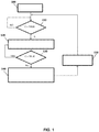
- FIG. 1 shows a schematic block diagram of a preferred embodiment of the method according to the invention performed by the processing unit CU of the system of Figure 2 .
- step 100 the conventional operation of the processing unit CU is started, receiving detections of the chemical-physical parameters from the detection probes and, on the basis of such detections, controlling the dispensing devices D1, D2 and D3.
- the processing unit CU simultaneously performs the method according to the invention.
- the condition C ERR1 OR ERR2 OR ERR3 is therefore checked through step 110 of monitoring the sensors F1, F2 and F3.
- step 120 In the case where an error condition occurs even only for one of the sensors F1, F2 and F3, then the condition C is true and the processing unit CU perform step 120 wherein it interrupts the chemical product dispensing process and signals, for instance through activation of luminous and/or acoustic signaling devices, the existence of an alarm condition.
- alarm condition persists as long as the condition C is true, thanks to the execution of step 130 of checking the value of the condition C.
- step 140 is performed where the inhibition of chemical product dispensing lasts for an additional time T1, T2 or T3, characteristic of the sensor F1, F2 or F3 (as well as of the characteristics of the duct on which this sensor is mounted) that is considered more characterizing for the correct operation of the circulation circuit of the swimming pool 200 and that is first detected in the relationship representing the condition C.
- the possible error condition that is first checked is ERR1
- the error condition of the primary sensor F1 hence in the case where the ERR1 condition is true
- the inhibition of the dosage will be maintained for a restoration time T plus an additional time T1 characteristic of the specific primary sensor F1 (as well as of the characteristics of the duct on which this sensor is mounted).
- the method according to the present invention provides for the check of the sensor F3 before checking the sensor F1.
- the relationship C ERR3 OR ERR2 OR ERR1 is therefore checked, thus the dosage inhibition will be maintained for a restoration time T plus an additional time T3 characteristic of the specific sensor F3 (as well as of the characteristics of the duct on which this sensor is mounted).
- step 150 the method performs step 150 wherein the possible activation of the dispensing devices D1, D2 and D3 is re-enabled and it returns to step 110.
- the method according to the invention enables or disables the activation of the dispensing devices D1, D2 and D3 irrespective of whether the processing unit CU recognizes the actual need to activate such dispensing devices D1, D2 and D3 or not.
- Discriminating the additional inhibition times T1, T2 or T3, characteristic of a specific sensor F1, F2 or F3, can be very useful because, depending on the point of the system where the flow problem occurs, it may be necessary to wait for a longer or shorter time before returning to the normal dosage of chemical product.
- the characteristic of possibly configuring (i.e. adjusting) the additional times T1, T2, and T3, advantageously allows an optimisation of the restoration times of the circulation system following, for instance, a voluntary shutdown or an unexpected block. Also, this further allows to render the method and the system according to the invention flexible and easily adaptable to different configurations and types of hydraulic circuit, due for instance to different volumes of water (or other liquid), ducts of different length and/or cross-section, circuits with portions having pressure drops.
- the sensors F1, F2, and F3 it is possible to configure the sensors F1, F2, and F3 so that they have the same value of additional time T1, T2, and T3, respectively, or, alternatively, so as to set a value of additional time different for each sensor F1, F2, and F3.
- a check of the error condition of the sensor having the longest restoration time is convenient in the case where it is desired to work in safe conditions and to ensure that the whole system is in steady state at the moment when the chemical product dispensing is restored, for instance in large systems with very high inertia.
- a check of the error condition of the sensor having the shortest restoration time is convenient where it is desired to work in conditions of rapid restoration of the system steady state conditions, for instance in small size swimming pools and circulation systems where the system can be restored faster.
- the expiry of the additional time T1, T2 or T3 in step 140 can be computed by the processing unit CU through a conventional decrement of a register initialized to the additional inhibition time, whereby, when such register reaches a zero value, step 150 is performed.
- the processing unit CU can control the dispensing devices D1, D2 and D3 so as to dispense proportionally reduced doses of chemical products.
- the present invention also comprises an implementation of the described method through a computer program.
- the computer program can be stored in a memory medium, for instance readable through a programmable electronic device.
- the computer program can be implemented by developing a software that can be supported by any programmable electronic device.
Landscapes
- Chemical & Material Sciences (AREA)
- Environmental & Geological Engineering (AREA)
- Organic Chemistry (AREA)
- Life Sciences & Earth Sciences (AREA)
- Hydrology & Water Resources (AREA)
- Engineering & Computer Science (AREA)
- Water Supply & Treatment (AREA)
- Health & Medical Sciences (AREA)
- Medicinal Chemistry (AREA)
- Feeding, Discharge, Calcimining, Fusing, And Gas-Generation Devices (AREA)
- Pipeline Systems (AREA)
- Grinding-Machine Dressing And Accessory Apparatuses (AREA)
- Control Of Non-Electrical Variables (AREA)
- Coating Apparatus (AREA)
- Sampling And Sample Adjustment (AREA)
Claims (8)
- Einstellungsverfahren zum Einstellen der Abgabe mindestens eines chemischen Produkts in einem hydraulischen Zirkulationskreis mit einem oder mehreren Zweigen (230, 240, 250), wobei mindestens eine Abgabevorrichtung (D1, D2, D3) dazu konfiguriert ist, wenn sie aktiviert ist, mindestens ein zugehöriges chemisches Produkt in den hydraulischen Zirkulationskreis abzugeben, umfassend die folgenden Schritte:- Detektieren einer oder mehrerer Flüssigkeitsflussraten in einem oder mehreren zugehörigen Zweigen (230, 240, 250) des hydraulischen Zirkulationskreises durch eine oder mehrere zugehörige Flussraten-Sensorvorrichtungen (F1, F2, F3);
wobei- wenn ein regulärer Zustand auftritt, bei dem die eine oder die mehreren Flüssigkeitsflussraten, die in dem einen oder den mehreren zugehörigen Zweigen (230, 240, 250) des hydraulischen Zirkulationskreises detektiert wurden nicht geringer oder größer sind als zugehörige Flussraten-Schwellenwerte, eine Aktivierung der mindestens einen Abgabevorrichtung (D1, D2, D3) ermöglicht wird, undwenn ein Fehlerzustand auftritt, der dadurch verursacht ist, dass mindestens eine der einen oder mehreren Flüssigkeitsflussraten, die in mindestens einem zugehörigen Zweig des einen oder der mehreren zugehörigen Zweige (230, 240, 250) des hydraulischen Zirkulationskreises detektiert wurden geringer ist oder nicht größer ist als ein zugehöriger Flussraten-Schwellenwert, eine Aktivierung der mindestens einen Abgabevorrichtung (D1, D2, D3) für eine Zeitdauer verhindert wird, die gleich einer Restaurationszeit (T) ist, während der die genannte mindestens eine detektierte Flüssigkeitsflussrate, die den Fehlerzustand verursacht, auf einen Wert wiederhergestellt wird, der nicht geringer oder höher ist als der genannte zugehörige Flussraten-Schwellenwert, plus einer zusätzlichen Verhinderungszeit (T1; T2; T3) die mit der einen oder den mehreren Flussraten-Sensorvorrichtungen (F1, F2, F3) assoziiert sind, wobei die zusätzliche Verhinderungszeit (T1; T2; T3) eine Hochfahrzeit für die eine oder die mehreren Flussraten-Sensorvorrichtungen (F1, F2, F3) ist, die gleich der Zeit ist, die notwendig ist, um Bedingungen eines stabilen Zustandes für die eine oder die mehreren Flussraten-Sensorvorrichtungen (F1, F2, F3) herzustellen, oder gleich der Zeit ist, die notwendig ist, dass der eine oder die mehreren Flussraten-Sensorvorrichtungen (F1, F2, F3) von einer Hochfahrkonfiguration in eine Betriebskonfiguration übergeht bzw. übergehen. - Einstellungsverfahren nach Anspruch 1, wobei die zusätzliche Verhinderungszeit (T1; T2; T3) mit der mindestens einen Flussraten-Sensorvorrichtung (F1, F2, F3) assoziiert ist, die den Fehlerzustand detektiert hat.
- Einstellungsverfahren nach Anspruch 1, wobei der hydraulische Zirkulationskreis zwei oder mehr Zweige (230, 240, 250) hat, in denen zwei oder mehr Flussraten-Sensorvorrichtungen (F1, F2, F3) zwei oder mehr zugehörige Flüssigkeitsflussraten detektieren, wobei eine zugehörige Hochfahrzeit (T1; T2; T3) mit einer jeden der zwei oder mehr Flussraten-Sensorvorrichtungen (F1, F2, F3) assoziiert ist, und wobei die zusätzliche Verhinderungszeit (T1; T2; T3) gleich der längsten der Hochfahrzeiten (T1; T2; T3) ist, die mit den zwei oder mehr Flussraten-Sensorvorrichtungen (F1, F2, F3) assoziiert sind.
- Einstellungsverfahren nach Anspruch 1, wobei der hydraulische Zirkulationskreis zwei oder mehr Zweige (230, 240, 250) hat, in denen zwei oder mehr Flussraten-Sensorvorrichtungen (F1, F2, F3) zwei oder mehr zugehörige Flüssigkeitsflussraten detektieren, wobei eine zugehörige Hochfahrzeit (T1; T2; T3) mit einer jeden der zwei oder mehr Flussraten-Sensorvorrichtungen (F1, F2, F3) assoziiert ist, und wobei die zusätzliche Verhinderungszeit (T1; T2; T3) gleich der kürzesten der Hochfahrzeiten (T1; T2; T3) ist, die mit den zwei oder mehr Flussraten-Sensorvorrichtungen (F1, F2, F3) assoziiert sind.
- Einstellungsverfahren nach einem der vorhergehenden Ansprüche, wobei mindestens eine Flussraten-Sensorvorrichtung (F1, F2, F3) ein flussbasierter Schalter oder ein Flussmessgerät ist.
- Einstellungssystem, das dazu konfiguriert ist, die Abgabe mindestens eines chemischen Produkts in einem hydraulischen Zirkulationskreis einzustellen, der einen oder mehrere Zweige (230, 240, 250) hat, das folgendes umfasst:- mindestens eine Abgabevorrichtung (D1, D2, D3) die dazu konfiguriert ist, wenn sie aktiviert ist, mindestens ein zugehöriges chemisches Produkt in den hydraulischen Zirkulationskreis abzugeben;- eine oder mehrere Flussraten-Sensorvorrichtungen (F1; F2; F3), die dazu konfigurieren ist einem Flussratenwert in einem oder mehreren Zweigen (230, 240, 250) des hydraulischen Zirkulationskreises zu detektieren;- und eine Prozessoreinheit (CU), die dazu konfiguriert ist, das Einstellungsverfahren nach einem der Ansprüche 1-5 durchzuführen.
- Computerprogramm, welches Befehle enthält, die, wenn sie von einer Prozessoreinheit (CU) ausgeführt werden, veranlassen, dass die Prozessoreinheit (CU) das Einstellverfahren nach einem der Ansprüche 1-5 ausführt.
- Computerlesbares Medium, welches das Computerprogramm nach dem vorherigen Anspruch speichert.
Applications Claiming Priority (2)
| Application Number | Priority Date | Filing Date | Title |
|---|---|---|---|
| IT102016000110606A IT201600110606A1 (it) | 2016-11-03 | 2016-11-03 | Metodo e sistema di regolazione per l’erogazione di un agente chimico |
| PCT/IB2017/056897 WO2018083665A1 (en) | 2016-11-03 | 2017-11-03 | Adjusting method and system for dispensing chemical products |
Publications (2)
| Publication Number | Publication Date |
|---|---|
| EP3535217A1 EP3535217A1 (de) | 2019-09-11 |
| EP3535217B1 true EP3535217B1 (de) | 2020-04-22 |
Family
ID=58228404
Family Applications (1)
| Application Number | Title | Priority Date | Filing Date |
|---|---|---|---|
| EP17808161.8A Active EP3535217B1 (de) | 2016-11-03 | 2017-11-03 | Einstellungsverfahren und system zur ausgabe von chemischen produkten |
Country Status (13)
| Country | Link |
|---|---|
| US (1) | US10961129B2 (de) |
| EP (1) | EP3535217B1 (de) |
| JP (1) | JP7015302B2 (de) |
| CN (1) | CN110088050B (de) |
| AU (1) | AU2017354108B2 (de) |
| CA (1) | CA3041199A1 (de) |
| ES (1) | ES2796529T3 (de) |
| IL (1) | IL266196B (de) |
| IT (1) | IT201600110606A1 (de) |
| MX (1) | MX394573B (de) |
| RU (1) | RU2727601C1 (de) |
| WO (1) | WO2018083665A1 (de) |
| ZA (1) | ZA201903330B (de) |
Family Cites Families (14)
| Publication number | Priority date | Publication date | Assignee | Title |
|---|---|---|---|---|
| US4224154A (en) * | 1978-12-20 | 1980-09-23 | Steininger Jacques M | Swimming pool chemical control system |
| JP3672613B2 (ja) * | 1995-04-05 | 2005-07-20 | 蛇の目ミシン工業株式会社 | 浴水循環装置 |
| JPH09285412A (ja) * | 1996-04-25 | 1997-11-04 | Mitsubishi Electric Corp | 浴水循環濾過装置 |
| US6149801A (en) * | 1997-08-08 | 2000-11-21 | Water Pik, Inc,. | Water treatment device with volumetric monitoring features |
| US6337024B1 (en) * | 1999-07-13 | 2002-01-08 | Hammonds Technical Services, Inc. | Chlorination apparatus and method |
| JP2007111575A (ja) * | 2005-10-18 | 2007-05-10 | Sankyo System Kk | 水循環システム並びにそれを実行するためのプログラム |
| US20090200245A1 (en) * | 2008-02-08 | 2009-08-13 | Steinbrueck Brett D | System for Controlling Water in an Aquatic Facility |
| RU2424200C2 (ru) * | 2009-07-30 | 2011-07-20 | ООО "Стройинжиниринг СМ" | Система очистки и обеззараживания воды в плавательных бассейнах |
| CA2799960C (en) * | 2010-05-21 | 2016-10-11 | Gecko Alliance Group Inc. | Method and system for sanitizing water in a bathing unit providing diagnostic capabilities and control interface for use in connection with same |
| RU109127U1 (ru) * | 2011-04-04 | 2011-10-10 | Юрий Григорьевич Кокарев | Установка для очистки и дезинфекции воды в плавательном бассейне |
| US20140266574A1 (en) * | 2013-03-15 | 2014-09-18 | Ovie V. Whitson, JR. | System and method for monitoring water levels |
| WO2015129618A1 (ja) * | 2014-02-28 | 2015-09-03 | 栗田工業株式会社 | ボイラの薬品注入制御装置及び方法 |
| US11104587B2 (en) * | 2016-04-14 | 2021-08-31 | Nch Corporation | System and method for automated control, feed, delivery verification, and inventory management of corrosion and scale treatment products for water systems |
| US9994466B2 (en) * | 2016-10-04 | 2018-06-12 | Georgia Aquarium Inc. | Removing nitrate from water |
-
2016
- 2016-11-03 IT IT102016000110606A patent/IT201600110606A1/it unknown
-
2017
- 2017-11-03 CN CN201780067305.6A patent/CN110088050B/zh active Active
- 2017-11-03 AU AU2017354108A patent/AU2017354108B2/en active Active
- 2017-11-03 EP EP17808161.8A patent/EP3535217B1/de active Active
- 2017-11-03 CA CA3041199A patent/CA3041199A1/en active Pending
- 2017-11-03 ES ES17808161T patent/ES2796529T3/es active Active
- 2017-11-03 US US16/346,836 patent/US10961129B2/en active Active
- 2017-11-03 JP JP2019521104A patent/JP7015302B2/ja active Active
- 2017-11-03 IL IL266196A patent/IL266196B/en unknown
- 2017-11-03 RU RU2019112146A patent/RU2727601C1/ru active
- 2017-11-03 WO PCT/IB2017/056897 patent/WO2018083665A1/en not_active Ceased
- 2017-11-03 MX MX2019004631A patent/MX394573B/es unknown
-
2019
- 2019-05-27 ZA ZA2019/03330A patent/ZA201903330B/en unknown
Non-Patent Citations (1)
| Title |
|---|
| None * |
Also Published As
| Publication number | Publication date |
|---|---|
| IL266196B (en) | 2022-08-01 |
| EP3535217A1 (de) | 2019-09-11 |
| IT201600110606A1 (it) | 2018-05-03 |
| US10961129B2 (en) | 2021-03-30 |
| JP7015302B2 (ja) | 2022-02-02 |
| WO2018083665A1 (en) | 2018-05-11 |
| CN110088050A (zh) | 2019-08-02 |
| JP2020500102A (ja) | 2020-01-09 |
| AU2017354108B2 (en) | 2022-08-25 |
| IL266196A (en) | 2019-06-30 |
| RU2727601C1 (ru) | 2020-07-22 |
| BR112019008185A2 (pt) | 2019-07-09 |
| CA3041199A1 (en) | 2018-05-11 |
| MX394573B (es) | 2025-03-24 |
| ES2796529T3 (es) | 2020-11-27 |
| US20200055742A1 (en) | 2020-02-20 |
| CN110088050B (zh) | 2022-07-22 |
| AU2017354108A1 (en) | 2019-06-06 |
| MX2019004631A (es) | 2019-07-15 |
| ZA201903330B (en) | 2020-02-26 |
Similar Documents
| Publication | Publication Date | Title |
|---|---|---|
| US20240091423A1 (en) | Water Treatment Systems, Devices, and Methods for Fluid Preparation | |
| ES2384623T3 (es) | Controles de un sistema de filtrado | |
| US4897184A (en) | Fluid flow apparatus control and monitoring | |
| CN107296989A (zh) | 排空用于体外血液治疗的装置的方法 | |
| EP3535217B1 (de) | Einstellungsverfahren und system zur ausgabe von chemischen produkten | |
| WO2017128570A1 (zh) | 在线监测系统 | |
| BR112019008185B1 (pt) | Método e sistema de ajuste para a dispensação de produtos químicos e meio legível por computador | |
| KR20200055390A (ko) | 스케일 제거 크리닝 작동을 구비한 알칼리 이온수기 및 그의 제어방법 | |
| JP2019018185A (ja) | 水処理システムの制御装置 | |
| US6595390B1 (en) | Method and apparatus for dispensing fluid doses | |
| US11067346B2 (en) | Cooling tower adjusting method and system | |
| JPH10131869A (ja) | 排水量制御装置 | |
| WO2014064302A1 (es) | Procedimiento para la gestión del agua en una piscina | |
| CN203324722U (zh) | 一种钢丝酸洗磷化废水处理系统自动控制装置 | |
| JP2024004225A5 (de) | ||
| WO2021107906A1 (en) | A water treatment device | |
| US20250262363A1 (en) | Blood Purification Device | |
| CN218810932U (zh) | 一种混流式泳池水质自动检测与消毒系统 | |
| JP2021084072A (ja) | 浄水器 | |
| JP2511547Y2 (ja) | 塩素注入の注入断検出装置 | |
| JP2024006785A (ja) | 透析排水処理システム | |
| JPH02293090A (ja) | 下水処理の消毒液過注入検出装置 | |
| WO2021010377A1 (ja) | 液体処理装置、液体浄化システム | |
| JPH0398607A (ja) | 風呂用殺菌装置におけるフィルターの目づまり検出装置 | |
| WO2014064301A1 (es) | Procedimiento para la gestión del agua en una piscina |
Legal Events
| Date | Code | Title | Description |
|---|---|---|---|
| STAA | Information on the status of an ep patent application or granted ep patent |
Free format text: STATUS: UNKNOWN |
|
| STAA | Information on the status of an ep patent application or granted ep patent |
Free format text: STATUS: THE INTERNATIONAL PUBLICATION HAS BEEN MADE |
|
| PUAI | Public reference made under article 153(3) epc to a published international application that has entered the european phase |
Free format text: ORIGINAL CODE: 0009012 |
|
| STAA | Information on the status of an ep patent application or granted ep patent |
Free format text: STATUS: REQUEST FOR EXAMINATION WAS MADE |
|
| 17P | Request for examination filed |
Effective date: 20190531 |
|
| AK | Designated contracting states |
Kind code of ref document: A1 Designated state(s): AL AT BE BG CH CY CZ DE DK EE ES FI FR GB GR HR HU IE IS IT LI LT LU LV MC MK MT NL NO PL PT RO RS SE SI SK SM TR |
|
| AX | Request for extension of the european patent |
Extension state: BA ME |
|
| GRAP | Despatch of communication of intention to grant a patent |
Free format text: ORIGINAL CODE: EPIDOSNIGR1 |
|
| STAA | Information on the status of an ep patent application or granted ep patent |
Free format text: STATUS: GRANT OF PATENT IS INTENDED |
|
| DAV | Request for validation of the european patent (deleted) | ||
| DAX | Request for extension of the european patent (deleted) | ||
| INTG | Intention to grant announced |
Effective date: 20191115 |
|
| GRAS | Grant fee paid |
Free format text: ORIGINAL CODE: EPIDOSNIGR3 |
|
| GRAA | (expected) grant |
Free format text: ORIGINAL CODE: 0009210 |
|
| STAA | Information on the status of an ep patent application or granted ep patent |
Free format text: STATUS: THE PATENT HAS BEEN GRANTED |
|
| AK | Designated contracting states |
Kind code of ref document: B1 Designated state(s): AL AT BE BG CH CY CZ DE DK EE ES FI FR GB GR HR HU IE IS IT LI LT LU LV MC MK MT NL NO PL PT RO RS SE SI SK SM TR |
|
| REG | Reference to a national code |
Ref country code: CH Ref legal event code: EP |
|
| REG | Reference to a national code |
Ref country code: IE Ref legal event code: FG4D |
|
| REG | Reference to a national code |
Ref country code: DE Ref legal event code: R096 Ref document number: 602017015400 Country of ref document: DE |
|
| REG | Reference to a national code |
Ref country code: AT Ref legal event code: REF Ref document number: 1259863 Country of ref document: AT Kind code of ref document: T Effective date: 20200515 |
|
| REG | Reference to a national code |
Ref country code: LT Ref legal event code: MG4D |
|
| REG | Reference to a national code |
Ref country code: NL Ref legal event code: MP Effective date: 20200422 |
|
| PG25 | Lapsed in a contracting state [announced via postgrant information from national office to epo] |
Ref country code: LT Free format text: LAPSE BECAUSE OF FAILURE TO SUBMIT A TRANSLATION OF THE DESCRIPTION OR TO PAY THE FEE WITHIN THE PRESCRIBED TIME-LIMIT Effective date: 20200422 Ref country code: PT Free format text: LAPSE BECAUSE OF FAILURE TO SUBMIT A TRANSLATION OF THE DESCRIPTION OR TO PAY THE FEE WITHIN THE PRESCRIBED TIME-LIMIT Effective date: 20200824 Ref country code: FI Free format text: LAPSE BECAUSE OF FAILURE TO SUBMIT A TRANSLATION OF THE DESCRIPTION OR TO PAY THE FEE WITHIN THE PRESCRIBED TIME-LIMIT Effective date: 20200422 Ref country code: NL Free format text: LAPSE BECAUSE OF FAILURE TO SUBMIT A TRANSLATION OF THE DESCRIPTION OR TO PAY THE FEE WITHIN THE PRESCRIBED TIME-LIMIT Effective date: 20200422 Ref country code: IS Free format text: LAPSE BECAUSE OF FAILURE TO SUBMIT A TRANSLATION OF THE DESCRIPTION OR TO PAY THE FEE WITHIN THE PRESCRIBED TIME-LIMIT Effective date: 20200822 Ref country code: SE Free format text: LAPSE BECAUSE OF FAILURE TO SUBMIT A TRANSLATION OF THE DESCRIPTION OR TO PAY THE FEE WITHIN THE PRESCRIBED TIME-LIMIT Effective date: 20200422 Ref country code: NO Free format text: LAPSE BECAUSE OF FAILURE TO SUBMIT A TRANSLATION OF THE DESCRIPTION OR TO PAY THE FEE WITHIN THE PRESCRIBED TIME-LIMIT Effective date: 20200722 Ref country code: GR Free format text: LAPSE BECAUSE OF FAILURE TO SUBMIT A TRANSLATION OF THE DESCRIPTION OR TO PAY THE FEE WITHIN THE PRESCRIBED TIME-LIMIT Effective date: 20200723 |
|
| REG | Reference to a national code |
Ref country code: AT Ref legal event code: MK05 Ref document number: 1259863 Country of ref document: AT Kind code of ref document: T Effective date: 20200422 |
|
| REG | Reference to a national code |
Ref country code: ES Ref legal event code: FG2A Ref document number: 2796529 Country of ref document: ES Kind code of ref document: T3 Effective date: 20201127 |
|
| PG25 | Lapsed in a contracting state [announced via postgrant information from national office to epo] |
Ref country code: RS Free format text: LAPSE BECAUSE OF FAILURE TO SUBMIT A TRANSLATION OF THE DESCRIPTION OR TO PAY THE FEE WITHIN THE PRESCRIBED TIME-LIMIT Effective date: 20200422 Ref country code: LV Free format text: LAPSE BECAUSE OF FAILURE TO SUBMIT A TRANSLATION OF THE DESCRIPTION OR TO PAY THE FEE WITHIN THE PRESCRIBED TIME-LIMIT Effective date: 20200422 Ref country code: BG Free format text: LAPSE BECAUSE OF FAILURE TO SUBMIT A TRANSLATION OF THE DESCRIPTION OR TO PAY THE FEE WITHIN THE PRESCRIBED TIME-LIMIT Effective date: 20200722 Ref country code: HR Free format text: LAPSE BECAUSE OF FAILURE TO SUBMIT A TRANSLATION OF THE DESCRIPTION OR TO PAY THE FEE WITHIN THE PRESCRIBED TIME-LIMIT Effective date: 20200422 |
|
| PG25 | Lapsed in a contracting state [announced via postgrant information from national office to epo] |
Ref country code: AL Free format text: LAPSE BECAUSE OF FAILURE TO SUBMIT A TRANSLATION OF THE DESCRIPTION OR TO PAY THE FEE WITHIN THE PRESCRIBED TIME-LIMIT Effective date: 20200422 |
|
| REG | Reference to a national code |
Ref country code: DE Ref legal event code: R097 Ref document number: 602017015400 Country of ref document: DE |
|
| PG25 | Lapsed in a contracting state [announced via postgrant information from national office to epo] |
Ref country code: CZ Free format text: LAPSE BECAUSE OF FAILURE TO SUBMIT A TRANSLATION OF THE DESCRIPTION OR TO PAY THE FEE WITHIN THE PRESCRIBED TIME-LIMIT Effective date: 20200422 Ref country code: RO Free format text: LAPSE BECAUSE OF FAILURE TO SUBMIT A TRANSLATION OF THE DESCRIPTION OR TO PAY THE FEE WITHIN THE PRESCRIBED TIME-LIMIT Effective date: 20200422 Ref country code: AT Free format text: LAPSE BECAUSE OF FAILURE TO SUBMIT A TRANSLATION OF THE DESCRIPTION OR TO PAY THE FEE WITHIN THE PRESCRIBED TIME-LIMIT Effective date: 20200422 Ref country code: EE Free format text: LAPSE BECAUSE OF FAILURE TO SUBMIT A TRANSLATION OF THE DESCRIPTION OR TO PAY THE FEE WITHIN THE PRESCRIBED TIME-LIMIT Effective date: 20200422 Ref country code: SM Free format text: LAPSE BECAUSE OF FAILURE TO SUBMIT A TRANSLATION OF THE DESCRIPTION OR TO PAY THE FEE WITHIN THE PRESCRIBED TIME-LIMIT Effective date: 20200422 Ref country code: DK Free format text: LAPSE BECAUSE OF FAILURE TO SUBMIT A TRANSLATION OF THE DESCRIPTION OR TO PAY THE FEE WITHIN THE PRESCRIBED TIME-LIMIT Effective date: 20200422 |
|
| PG25 | Lapsed in a contracting state [announced via postgrant information from national office to epo] |
Ref country code: SK Free format text: LAPSE BECAUSE OF FAILURE TO SUBMIT A TRANSLATION OF THE DESCRIPTION OR TO PAY THE FEE WITHIN THE PRESCRIBED TIME-LIMIT Effective date: 20200422 Ref country code: PL Free format text: LAPSE BECAUSE OF FAILURE TO SUBMIT A TRANSLATION OF THE DESCRIPTION OR TO PAY THE FEE WITHIN THE PRESCRIBED TIME-LIMIT Effective date: 20200422 |
|
| PLBE | No opposition filed within time limit |
Free format text: ORIGINAL CODE: 0009261 |
|
| STAA | Information on the status of an ep patent application or granted ep patent |
Free format text: STATUS: NO OPPOSITION FILED WITHIN TIME LIMIT |
|
| 26N | No opposition filed |
Effective date: 20210125 |
|
| PG25 | Lapsed in a contracting state [announced via postgrant information from national office to epo] |
Ref country code: MC Free format text: LAPSE BECAUSE OF FAILURE TO SUBMIT A TRANSLATION OF THE DESCRIPTION OR TO PAY THE FEE WITHIN THE PRESCRIBED TIME-LIMIT Effective date: 20200422 |
|
| REG | Reference to a national code |
Ref country code: CH Ref legal event code: PL |
|
| PG25 | Lapsed in a contracting state [announced via postgrant information from national office to epo] |
Ref country code: LU Free format text: LAPSE BECAUSE OF NON-PAYMENT OF DUE FEES Effective date: 20201103 |
|
| REG | Reference to a national code |
Ref country code: BE Ref legal event code: MM Effective date: 20201130 |
|
| PG25 | Lapsed in a contracting state [announced via postgrant information from national office to epo] |
Ref country code: CH Free format text: LAPSE BECAUSE OF NON-PAYMENT OF DUE FEES Effective date: 20201130 Ref country code: LI Free format text: LAPSE BECAUSE OF NON-PAYMENT OF DUE FEES Effective date: 20201130 |
|
| PG25 | Lapsed in a contracting state [announced via postgrant information from national office to epo] |
Ref country code: IE Free format text: LAPSE BECAUSE OF NON-PAYMENT OF DUE FEES Effective date: 20201103 |
|
| PG25 | Lapsed in a contracting state [announced via postgrant information from national office to epo] |
Ref country code: MT Free format text: LAPSE BECAUSE OF FAILURE TO SUBMIT A TRANSLATION OF THE DESCRIPTION OR TO PAY THE FEE WITHIN THE PRESCRIBED TIME-LIMIT Effective date: 20200422 Ref country code: CY Free format text: LAPSE BECAUSE OF FAILURE TO SUBMIT A TRANSLATION OF THE DESCRIPTION OR TO PAY THE FEE WITHIN THE PRESCRIBED TIME-LIMIT Effective date: 20200422 |
|
| PG25 | Lapsed in a contracting state [announced via postgrant information from national office to epo] |
Ref country code: MK Free format text: LAPSE BECAUSE OF FAILURE TO SUBMIT A TRANSLATION OF THE DESCRIPTION OR TO PAY THE FEE WITHIN THE PRESCRIBED TIME-LIMIT Effective date: 20200422 |
|
| PG25 | Lapsed in a contracting state [announced via postgrant information from national office to epo] |
Ref country code: BE Free format text: LAPSE BECAUSE OF NON-PAYMENT OF DUE FEES Effective date: 20201130 |
|
| P01 | Opt-out of the competence of the unified patent court (upc) registered |
Effective date: 20230601 |
|
| PG25 | Lapsed in a contracting state [announced via postgrant information from national office to epo] |
Ref country code: SI Free format text: LAPSE BECAUSE OF FAILURE TO SUBMIT A TRANSLATION OF THE DESCRIPTION OR TO PAY THE FEE WITHIN THE PRESCRIBED TIME-LIMIT Effective date: 20200422 |
|
| PGFP | Annual fee paid to national office [announced via postgrant information from national office to epo] |
Ref country code: ES Payment date: 20250102 Year of fee payment: 8 |
|
| PGFP | Annual fee paid to national office [announced via postgrant information from national office to epo] |
Ref country code: DE Payment date: 20251112 Year of fee payment: 9 |
|
| PGFP | Annual fee paid to national office [announced via postgrant information from national office to epo] |
Ref country code: GB Payment date: 20251111 Year of fee payment: 9 |
|
| PGFP | Annual fee paid to national office [announced via postgrant information from national office to epo] |
Ref country code: IT Payment date: 20251113 Year of fee payment: 9 |
|
| PGFP | Annual fee paid to national office [announced via postgrant information from national office to epo] |
Ref country code: FR Payment date: 20251111 Year of fee payment: 9 |
|
| PGFP | Annual fee paid to national office [announced via postgrant information from national office to epo] |
Ref country code: TR Payment date: 20251030 Year of fee payment: 9 |