EP3535136B1 - Radstütze und rad für elektrischen transformator - Google Patents
Radstütze und rad für elektrischen transformator Download PDFInfo
- Publication number
- EP3535136B1 EP3535136B1 EP17812036.6A EP17812036A EP3535136B1 EP 3535136 B1 EP3535136 B1 EP 3535136B1 EP 17812036 A EP17812036 A EP 17812036A EP 3535136 B1 EP3535136 B1 EP 3535136B1
- Authority
- EP
- European Patent Office
- Prior art keywords
- support
- roller
- wheel
- electric transformer
- pivot
- Prior art date
- Legal status (The legal status is an assumption and is not a legal conclusion. Google has not performed a legal analysis and makes no representation as to the accuracy of the status listed.)
- Active
Links
Images


Classifications
-
- B—PERFORMING OPERATIONS; TRANSPORTING
- B60—VEHICLES IN GENERAL
- B60B—VEHICLE WHEELS; CASTORS; AXLES FOR WHEELS OR CASTORS; INCREASING WHEEL ADHESION
- B60B33/00—Castors in general ; Anti-clogging castors
- B60B33/0047—Castors in general ; Anti-clogging castors characterised by details of the rolling axle
- B60B33/0049—Castors in general ; Anti-clogging castors characterised by details of the rolling axle the rolling axle being horizontal
-
- B—PERFORMING OPERATIONS; TRANSPORTING
- B60—VEHICLES IN GENERAL
- B60B—VEHICLE WHEELS; CASTORS; AXLES FOR WHEELS OR CASTORS; INCREASING WHEEL ADHESION
- B60B33/00—Castors in general ; Anti-clogging castors
- B60B33/0036—Castors in general ; Anti-clogging castors characterised by type of wheels
- B60B33/0039—Single wheels
-
- B—PERFORMING OPERATIONS; TRANSPORTING
- B60—VEHICLES IN GENERAL
- B60B—VEHICLE WHEELS; CASTORS; AXLES FOR WHEELS OR CASTORS; INCREASING WHEEL ADHESION
- B60B33/00—Castors in general ; Anti-clogging castors
- B60B33/0047—Castors in general ; Anti-clogging castors characterised by details of the rolling axle
- B60B33/0055—Castors in general ; Anti-clogging castors characterised by details of the rolling axle the rolling axle intersects swivel axis
-
- H—ELECTRICITY
- H01—ELECTRIC ELEMENTS
- H01F—MAGNETS; INDUCTANCES; TRANSFORMERS; SELECTION OF MATERIALS FOR THEIR MAGNETIC PROPERTIES
- H01F27/00—Details of transformers or inductances, in general
- H01F27/002—Arrangements provided on the transformer facilitating its transport
-
- B—PERFORMING OPERATIONS; TRANSPORTING
- B60—VEHICLES IN GENERAL
- B60B—VEHICLE WHEELS; CASTORS; AXLES FOR WHEELS OR CASTORS; INCREASING WHEEL ADHESION
- B60B2360/00—Materials; Physical forms thereof
- B60B2360/30—Synthetic materials
- B60B2360/34—Reinforced plastics
- B60B2360/341—Reinforced plastics with fibres
- B60B2360/3412—Glass fibres
-
- B—PERFORMING OPERATIONS; TRANSPORTING
- B60—VEHICLES IN GENERAL
- B60B—VEHICLE WHEELS; CASTORS; AXLES FOR WHEELS OR CASTORS; INCREASING WHEEL ADHESION
- B60B2900/00—Purpose of invention
- B60B2900/10—Reduction of
- B60B2900/111—Weight
-
- B—PERFORMING OPERATIONS; TRANSPORTING
- B60—VEHICLES IN GENERAL
- B60B—VEHICLE WHEELS; CASTORS; AXLES FOR WHEELS OR CASTORS; INCREASING WHEEL ADHESION
- B60B2900/00—Purpose of invention
- B60B2900/70—Adaptation for
- B60B2900/711—High loads, e.g. by reinforcements
Definitions
- the present invention relates to the sector of industrial wheels, particularly the sector of wheels for electric transformers, even more particularly the wheels for the movement of oil and resin electric transformers for distribution of electric energy.
- the wheel concept generally constituted by an element, denominated roller, rotating about a hub or shaft and turnably connected to a support fork, in turn connected to a mean to be moved.
- the weight of the electric transformer statically loads for a long time on a plurality of wheels, generally four, which consequently need to resist to the static deformations and to high static loads.
- An electric transformer for the distribution of electric energy also named distribution transformer
- the wheels supporting an electric transformer need to resist to high dynamic vertical loads which occur during the positioning on the floor of the electric transformer itself.
- the wheels of the electric transformer need to be occasionally rotated with respect to the electric transformer to allow diagonal or lateral displacements of the electric transformer. Consequently, the edge of the roller touching the ground and the connection area of the roller shaft with the fork are significantly exposed to lateral and torsional load respectively.
- the state of the art comprises wheels for electric transformers wherein the roller is made of cast iron, because of the good resistance to compression and hardness of this metal material.
- the cast iron rollers are very fragile and can easily break in case of collisions of the roller with the ground. Furthermore, these rollers are often not perfectly round and the rolling is often compromised.
- Wheels with nylon rollers are also known and allow to reduce manufacturing and logistic costs without compromising the resistance to compression and the hardness.
- the cast iron rollers are connected to a metallic support through a metallic shaft.
- the shaft is inserted in the cast iron roller and subsequently fixed to the support to permit the rolling of the roller with respect to the support.
- the cast iron rollers for electric transformers are painted.
- this painting can break or deteriorates, creating potential zones from which the corrosion can start.
- the eventual rust can create joining points between roller and metal hub, blocking the rolling of the wheel.
- nylon or cast iron wheels need to be hot-dip galvanized or painted.
- the transformer wheels known in the state of the art are heavy and consequently difficult to be transported.
- the wheels with cast iron rollers can weight 11 kg when the roller has a diameter of 200 mm, and, if the rollers are made of nylon, the weight of the wheel can be 6 kg for diameters of about 200 mm.
- the weight is about 2,4 kg, while for a wheel with nylon roller having a diameter of 125 mm the weight is 1,2 kg.
- the wheels have metal supports.
- nylon rollers of the state of the art use hubs, named also shafts, made of metal, which are not embedded in the roller.
- the hub can accidentally moves from the roller and/or the support, causing the block of the roller or even worst its rupture.
- a wheel support and a wheel for electrical transformer are known respectively from EP 2 241 455 A2 and WO 2015/004690 A1 .
- a wheel support for distribution electric transformer comprising:
- roller or its pivot
- the roller can be rapidly and safely coupled to the support, without the need for riveting the pivot over the support as in the case of existing wheels for electric transformer.
- said wheel support for an electric distribution transformer allows to resist to high vertical and lateral loads, both instantaneous or static.
- Said support so conceived is corrosion proof and excellently resists to high excursions of temperatures or humidity, without altering its mechanical or physic properties.
- the support so conceived is extremely light and consequently it's easily transportable.
- Said support can be entirely realized in polyamide, preferably PA 6 or PA 6,6.
- the polyamide is preferably reinforced with glass fiber to provide to the support the required mechanical resistance to vertical and lateral loads.
- the percentage of glass fiber can be comprised between 20% and 60%, preferably between 30% and 50%.
- This percentage further improves the mechanical properties of the support.
- the support can be moulded through injection moulding.
- This manufacturing technique is rapid and efficient and allow to obtain supports which are really consistent, in terms of tolerances and geometry, with the product design.
- the ribs of the support can be oriented in a substantially radial direction with respect to said portion configured to receive and turnably support a roller ad its pivot of the roller.
- This orientation of the ribs allows to efficiently unload the vertical loads acting on the support. Furthermore, these ribs increase the torsional resistance of the support itself about the vertical axis, so increasing the resistance to lateral loads.
- the support can be oriented with respect to the electric transformer by means of orientable rotable connection means.
- This orientable rotable connection means can comprise a threaded element, fittable in a first slot of the upper portion configured to receive at least in part the threaded element and to stop its rotation about a vertical axis.
- the threaded element being connectible with a complementary threaded element of the electric transformer for realizing said connection to the electric transformer.
- connection between said threaded element and said complementary threaded element of the electric transformer allows to realize a vertical fulcrum of the support with respect the transformer.
- These orientable rotable connection means can further comprise a hole or a bump arranged on a contact surface with the electric transformer of the upper portion and configured to set one or more orientations of connection of said support to said electric transformer.
- This hole or bump allows to set the orientation of the support relative to the transformer in an economic and simple way.
- the support can further comprise a lateral pit configured to cooperate with a lever for facilitating the rotation of the support relative to the electric transformer according to the vertical axis. This technical characteristic allows to rotate the support relative to the transformer even if the support is loaded with the weight of the transformer.
- the support can comprise an annular bush or an axial bearing inserted in a second slot of the upper portion of the support.
- said support comprises a couple of caps, each one configured to be snap-fitted to one of the vertical portions and blocking elements.
- the vertical portions of the support can comprise a stopping system configured to prevent the rotation of the roller about its rotational axis. Said system allows to lock the rotation of the roller and prevent the movement of the electric transformer.
- a second object of the present invention is a wheel comprising a support according to the first object of the present invention and a roller having a pivot made of composite material.
- the roller can comprise a pivot, integrally connected to the roller itself.
- Said roller can be entirely made of polyamide, preferably PA 6 or PA 6,6, reinforced with glass fiber in a weight percentage comprised between 20% and 60%, preferably between 30% and 50%.
- the roller so conceived can resist to high radial static compression loads, even higher than 10.000 N, preferably higher than 25.000 N.
- the roller can comprise a plurality of substantially radial ribs extending on both side of the roller from the pivot to a portion substantially cylindrical of the roller configured to roll on a flat surface or on the ground.
- Said roller can have a diameter comprised between 100 and 300 mm, preferably comprised between 125 and 200 mm.
- the support and the roller of the present invention can be extremely resistant to the corrosion, in particular the saline corrosion, to the humidity and to the extreme ambient temperatures.
- a further scope of the present invention is an electric transformer having a plurality of wheels according to the present invention.
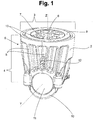
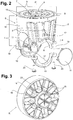
- Fig. 1 and 2 show a support according to the present invention wherein a fork 2 comprises a upper portion 3 configured for being connectible to the lower base of an electric transformer (not shown) and two vertical portions 4 extending from the upper portion 3 until to a portion able to receive a roller, or a pivot of the roller.
- the upper portion 3 comprises a upper surface 13 configured for connecting the support connection with a beam of the lower base of the electric transformer.
- Said surface 13 comprises a plurality of lightening recesses and a first slot configured to receive a threaded element 6, thus an element having a thread on the inner or outer surface, like for example a nut or a bolt.
- This slot has a shape configured to permit the insertion of the threaded element 6 and to stop its rotation about the vertical axis Z once inserted.
- said first slot is realized in the lower part of the upper portion 3 and has a threaded or hexagonal prism shape to receive a threaded element 6 having an outer surface with hexagonal cross-section, like a bolt or a nut.
- Said threaded element 6 is inserted in the first slot of the upper portion 3 up to an end of stroke wherein the element 6 touches a surface (not shown) of the upper portion 3 itself.
- the threaded element 6 is configured to cooperate with a bolt/nut of the electric transformer to realize a connection of the support S to the transformer itself.
- connection so realized with the transformer is of axial type and allows to rotate the support S relative to the electric transformer. It is so provided an orientable rotable connection.
- the support S comprises two first slots to receive two nuts or two bolts. Said slots have axes lying on a common plane, which in turn is orthogonal to the rotational axis Y of the roller R.
- said orientable rotable connection means can comprise a hole 7, a pit (not shown) or a pin (not shown) arranged on the contact surface 13 of the support with the electric transformer.
- Said hole 7 or pin are eccentric with respect to the rotational axis of the support Z.
- the transformer can be oriented respective the support by means of an element having a shape complementary to the hole 7.
- the contact surface of the electric transformer with the support S can comprise one or more vertical projections (not shown) each one adapted to enter in the hole 7 if a rotation of the support S brings the projection over said hole 7.
- said projections of the transformer can be arranged at 0°, 45° and 90° with respect to the wheelbase direction of the transformer, so to allow an orientation of the support S respectively at 0°, 45° or 90°.
- the transformer comprises one or more holes or pits (not shown), each one adapted to receive said projection if the rotation of the support S relative to the axis Z of a predetermined amount of degrees occurs.
- Said upper portion 3 of the support S can further comprise a second slot having a substantially annular shape, configured to receive a bushing 9 or alternatively an axial bearing (not shown).
- Said bushing 9 having an annular shape and can be realized in a material having a low friction coefficient, for example PTFE.
- the bushing 9 or the axial bearing facilitates the rotation of the support S with respect to the electric transformer.
- the fork 2 of the support S further comprises two vertical portions 4 extending vertically downwardly from the upper portion 3 and being monolithically connected to it.
- Said vertical portions 4 are the prongs of the fork and are configured to support a pivot.
- Said vertical portions comprise a plurality of strengthening ribs 5 oriented upward.
- Said ribs 5 can have a width comprised between 4 and 10 mm, preferably from 5 to 9 mm.
- Said ribs 5 are preferably oriented in a substantially radial manner with respect to the portion fitted to received said pivot or with respect to the rotational axis of the pivot/roller, thus to the axis Y. Substantially, the ribs 5 are oriented so to have a outer radial direction with respect to the axis Y.
- the ribs 5 extend from the portion of the support S configured to contain the pivot of the roller up to the upper portion 3, protruding outwardly with respect to the rotational axis Y.
- connection bands 18 have an architrave shape, preferably arched, and connect the upper portion 3 and the vertical portion 4 each other, strongly improving the resistance of the support S to lateral loads.
- Each one of the vertical portions 4 of the support S comprises, in its lower part, a portion configured to contain and turnably support a roller R and in particular its pivot 14.
- Said portion comprises a first sliding semi-cylindrical surface 8 configured to receive the pivot 14 and connection means 19 connectible to a blocking element 10.
- Said connecting element 10 comprises a second sliding semi-cylindrical surface 17 which, together with the first sliding semi-cylindrical surface 8, realizes a cylindrical sliding surface configured to contain and swivel support the roller R or its pivot 14.
- the roller R is so radially blocked but free to rotate about the support axis Y.
- Said sliding surfaces 8,17 can comprise a cylindrical bushing (not shown) to facilitate the rotation of the roller R.
- said sliding surfaces 8,17 can comprise respective circular traces wherein a lubricant can be arranged to facilitate the rolling.
- Each of the blocking element 10 further comprises means 20 able to cooperate with said connection means 19 to realize a connection between the blocking elements 10 and the vertical portions 4 of the support S.
- Said connection means 20 can be four screws, each one for each connection mean 19.
- Said blocking elements 10 can have an arched shape having said means 20 at the end and said sliding semi-cylindrical surface 17 at an intermediate portion.
- the circular holes that are obtained connecting the blocking element 10 to the vertical portions 4 of the support S can be closed through caps 11 configured to snap-fit themselves to respective vertical portions 4 and to the blocking elements 10.
- caps 11 avoid the entering of debris on the sliding surfaces 8,17.
- said cups 11 can be personalized with the manufacturer or customer name or with the model of transformer on which can be installed, facilitating the choice of the support from the user which is operating the maintenance of the electric transformer.
- One or both said vertical portions 4 can comprise a pit configured to cooperate with a lever for facilitating the rotation of the support S with respect to the electric transformer according to the vertical axis Z.
- This pit (not shown) allows the insertion of a lever (not shown) in the vertical portion 4, so that a rotation of the support can be performed acting on the lever.
- it can comprise, instead of said pit, a lateral protrusion 21, shown in figure 5 , comprising a hole 22 for the insertion of a lever.
- One or both of said vertical portions 4 can further comprise a stopping system 12 configured to stop the rotation of the roller R with respect to its rotational axis Y.
- this stopping system 12 comprises a passing through hole, preferably threaded, oriented parallel to the axis Y and arranged on one or both of said vertical portions 4.
- Said hole allows the insertion of a rod or the threading of a bolt (not shown), able to cooperate with the roller R to stop its rotation.
- a rod this can be inserted up to reach the roller R, so that the rotation of the roller R is limited by the contact of the rod with the ribs 15 of the roller R.
- This support S is realized entirely, or at least in all its parts except the caps 11 and/or the blocking elements 10 and/or the threaded element 6, in polyamide, also known as nylon, reinforced with glass fibers.
- polyamide also known as nylon, reinforced with glass fibers.
- the used polyamide is of the type PA 6 or PA 6,6.
- a weight percentage of glass fiber between 20% and 60% of standard type, is preferable. This percentage is particularly adapted for the use with distribution electric transformer, because laboratory tests have demonstrated high resistance levels to static and dynamics loads both radial or axial.
- this fiber can be carbon fiber.
- roller can be made of the same composite material.
- the material above-described is particularly adapted for the injection moulding, allowing a fast and economic realization of the support S and roller R.
- the injection moulding permits that finished pieces (support S or roller R) faithfully fit in term of dimensions and tolerances with the original design.
- This type of geometrical precision is not reachable with the cast iron rollers and with the metal supports actually known in the state of the art.
- This geometrical fidelity to the original project allows to facilitate the assembly of the wheel 1 for electric transformers, solving an inconvenient of the wheels actually available on the market.
- these supports S and rollers R made of this material can be resistant to the corrosion, for example the salt corrosion, and to the humidity, easily passing the tests of the rule NFA 91-020, without any surface coating.
- the supports S and the rollers R so conceived are also adapted to ambient wherein the temperature is particularly rigid, thus extremely hot or extremely cold. In particular, they can resist to temperatures ranging from -30°C and +135°C.
- the weight of support S and roller R in polyamide reinforced with glass fibers is lower than the weight of equivalent rollers available in the state of the art.
- the simple support S weights about 500 gr and the entire wheel, thus the roller R and the support S, weights about 900 gr.
- said roller R comprises a pivot or shaft 14 integral to the rest of the roller. Roller and pivot are monolithic and consequently made in a single piece.
- the roller R has a pass-through hole coaxial to the rotational axis.
- a cylindrical shaft having a length able to come out on both sides when the shaft is inserted in the roller.
- this shaft can be connected to the vertical portions of the support through the couple of blocking elements.
- the material used for manufacturing the roller R is polyamide, preferably polyamide PA 6 or PA 6,6, reinforced with glass fiber in a weight percentage comprised between 20% and 60%, preferably between 30% and 50%.
- the manufacturing method that can be used to mould is the injection.
- the roller R comprises radial ribs 15 on both sides and preferably a central septum 23 oriented orthogonally to the rotational axis of the roller R.
- Each rib 15 can have a "Y" shape with the root in proximity of the hub (or pivot) 14, to unload efficiently the forces toward the rotational axis.
- the ribs 15 extend from the hub 14 to a cylindrical portion 16.
- the roller R so conceived can rotate through this cylindrical portion 16 on a planar surface or on the ground.
- the roller R for electric transformers can have a diameter comprised between 30 and 300 mm, preferably between 125 and 200 mm.
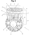
- Figure 4 shows the system assembles, thus a wheel 1 comprising a roller R and a support S as above-described.
- the assembly of said wheel 1 is particularly simplified with respect to the state of the art. It is enough to house the pivot 14 of the roller R on the sliding surface 8 of the support S, to position over the pivot 14 of the roller R the blocking elements 10 so to contact the connection means 19 of the support S, and finally to connect the two blocking elements 10 to the connection means 19 of the support S through the connecting means 20.
- the rolling surfaces can be lubricated during the assembly.
- the wheel 1 so conceived can be transported easily for its low weight.
- the wheel is also resistant to the corrosion, to the humidity and to high temperatures because of its composite material.
- said wheel 1 can be easily manufactured through injection moulding and it is easy to be assembled, requiring only elementary workshop tools.
- glass fibres reinforce the nylon, providing to the wheel 1 high mechanical resistance properties to static and dynamic loads, both vertical and lateral.
- said wheel 1 is configured to resist to a vertical load of 80 kN and a lateral load applied to the peripheral edge of the roller R of 2 kN.
- the support S, the roller R and the wheel 1 so conceived can be also employed to move heavy weight devices which are different from the electric transformers.
Landscapes
- Engineering & Computer Science (AREA)
- Mechanical Engineering (AREA)
- Power Engineering (AREA)
- Rolls And Other Rotary Bodies (AREA)
- Rolling Contact Bearings (AREA)
- Electroplating Methods And Accessories (AREA)
Claims (15)
- Radstütze (S) für elektrischen Verteilertransformator, die folgendes umfasst:- eine Gabel (2), die folgendes umfasst:- ein Oberteil (3), das mit einem Elektrotransformator verbunden werden kann;- zwei vertikale Teile (4), die monolithisch mit dem Oberteil verbunden sind (3), von denen jedes einen Teil umfasst, der so gestaltet ist, eine Rolle (R) aufzunehmen und sie drehbar zu unterstützen, und dabei besonders einen Drehzapfen der Rolle (R);- ein paar Blockierelemente (10), von denen jedes so gestaltet ist, mit einem der vertikalen Teile (4) der Stütze (S) verbunden zu werden, um die besagte Rolle (R) und besonders ihren Drehzapfen (14) zu umfassen; wobei eine Charakterisierung dahingehend besteht, dass die Gabel aus einem Verbundstoff hergestellt ist und dass die besagten vertikalen Teile (4) eine Vielzahl an Rippen (5) enthalten, die von unten nach oben ausgerichtet sind.
- Radstütze (S) gemäß Anspruch 1, wobei der besagte Verbundstoff aus Polyamid besteht, vorzugsweise PA 6 oder PA 6,6, glasfaserverstärkt, und wobei vorzugsweise das Gewichtsprozent der Glasfaser zwischen 20 % und 60 % liegt, vorzugsweise zwischen 30 % und 50 %.
- Radstütze (S) gemäß aller vorhergehenden Ansprüche, wobei jede Rippe der besagten Vielzahl von Rippen (5) in einer im Wesentlichen radialen Richtung in Bezug auf den besagten Teil ausgerichtet ist, der so gestaltet ist, die Rolle (R) aufzunehmen und sie drehbar zu unterstützen und dabei besonders den Drehzapfen der Rolle (R).
- Radstütze (S) gemäß aller vorhergehenden Ansprüche, die ausrichtbare drehbare Verbindungsmittel umfassen, um die Verbindung der Stütze (S) in Bezug auf den Elektrotransformator in eine oder mehrere Richtungen zu orientieren, wobei die besagten ausrichtbaren drehbaren Verbindungsmittel ein gewindebehaftetes Element (6) umfassen, eine erste Aufnahme des Oberteils (3), die so gestaltet ist, zumindest teilweise das gewindebehaftete Element (6) aufzunehmen und seine Rotation um eine vertikale Achse (Z) zu stoppen. Das besagte gewindebehaftete Element (6) kann mit einem komplementären gewindebehafteten Element des Elektrotransformators verbunden werden, um besagte Verbindung mit dem Elektrotransformator zu realisieren.
- Radstütze (S) gemäß Anspruch 4, wobei die besagten ausrichtbaren drehbaren Verbindungsmittel weiterhin ein Loch (7) oder eine Erhebung umfassen, die auf einer Kontaktfläche (13) mit dem Elektrotransformator des Oberteils (3) angeordnet sind und so gestaltet sind, eine oder mehrere Ausrichtungen der Verbindung der besagten Stütze (S) zum besagten Elektrotransformator einzustellen.
- Radstütze (S) gemäß aller vorhergehenden Ansprüche, wobei einer oder beide vertikale Teile eine Vertiefung umfassen, die mit einem Hebel zusammenwirkt, um die Rotation der Stütze (S) in Bezug auf den Elektrotransformator entsprechend der vertikalen Achse (Z) zu erleichtern.
- Radstütze (S) gemäß aller vorhergehenden Ansprüche, die weiterhin eine ringförmige Buchse (9) oder ein Axiallager umfasst, das in eine zweite Aufnahme des Oberteils (3) der Stütze (S) eingelassen ist und so gestaltet ist, die Rotation der Stütze (S) in Bezug auf die vertikale Achse (Z) zu unterstützen.
- Radstütze (S) gemäß Anspruch 1, die weiterhin ein paar Verschlusskappen (11) umfasst, die so gestaltet sind, in die vertikalen Teile (4) und Blockierelemente (10) einzurasten.
- Radstütze (S) gemäß aller vorhergehenden Ansprüche, wobei einer oder beide der besagten vertikalen Teile (4) der Stütze (S) ein Anhaltesystem (12) umfassen, das so gestaltet ist, die Rotation der Rolle (R) in Bezug zu ihrer Rotationsachse (Y) anzuhalten.
- Rad (1) für den Elektrotransformator, das eine Stütze (S) gemäß einem oder mehreren vorhergehenden Ansprüchen und eine Rolle (R) umfasst, die vollständig aus Verbundstoff hergestellt ist, und einen Drehzapfen (14) umfasst, der drehbar mit der Stütze (S) verbunden ist; vorzugsweise ist besagter Drehzapfen (14) ein integraler Bestandteil der Rolle (R).
- Rad (1) gemäß Anspruch 10, wobei besagter Verbundstoff der Rolle (R) aus Polyamid besteht, vorzugsweise PA 6 oder PA 6,6, Glasfaser mit einem Gewichtsprozent zwischen 20 % und 60 %, vorzugsweise zwischen 30 % und 50 %.
- Rad (1) gemäß Anspruch 10 oder 11, wobei besagte Rolle (R) eine Vielzahl an radialen Rippen (15) umfasst, die sich an beiden Seiten der Rolle (R) vom Drehzapfen (14) zu einem im Wesentlichen zylindrischen Teil (16) der Rolle (R) erstrecken, der so gestaltet ist, um auf einer flachen Oberfläche oder auf dem Boden zu rollen.
- Rad (1) gemäß aller Ansprüche von 10 bis 12, wobei besagte Rolle (R) einen Durchmesser zwischen 100 und 300 mm hat, vorzugsweise zwischen 125 und 200 mm.
- Rad (1) gemäß Anspruch 13, das so gestaltet ist, einer vertikalen Belastung von 80 kN und einer seitlichen Belastung von 2 kN, die auf dem äußeren Rand der Rolle (R) lastet, zu widerstehen.
- Elektrischer Verteilertransformator, der eine Vielzahl von Rädern gemäß der Ansprüche 13 oder 14 umfasst.
Priority Applications (1)
| Application Number | Priority Date | Filing Date | Title |
|---|---|---|---|
| PL17812036T PL3535136T3 (pl) | 2016-11-07 | 2017-10-30 | Wspornik koła i koło dla transformatora elektrycznego |
Applications Claiming Priority (2)
| Application Number | Priority Date | Filing Date | Title |
|---|---|---|---|
| IT102016000110680A IT201600110680A1 (it) | 2016-11-07 | 2016-11-07 | Supporto,rullo e ruota per trasformatori elettrici |
| PCT/IB2017/001306 WO2018083527A1 (en) | 2016-11-07 | 2017-10-30 | Wheel support and wheel for electric transformer |
Publications (2)
| Publication Number | Publication Date |
|---|---|
| EP3535136A1 EP3535136A1 (de) | 2019-09-11 |
| EP3535136B1 true EP3535136B1 (de) | 2020-09-16 |
Family
ID=58266021
Family Applications (1)
| Application Number | Title | Priority Date | Filing Date |
|---|---|---|---|
| EP17812036.6A Active EP3535136B1 (de) | 2016-11-07 | 2017-10-30 | Radstütze und rad für elektrischen transformator |
Country Status (5)
| Country | Link |
|---|---|
| EP (1) | EP3535136B1 (de) |
| CN (1) | CN109922973A (de) |
| IT (1) | IT201600110680A1 (de) |
| PL (1) | PL3535136T3 (de) |
| WO (1) | WO2018083527A1 (de) |
Families Citing this family (2)
| Publication number | Priority date | Publication date | Assignee | Title |
|---|---|---|---|---|
| CN112908622A (zh) * | 2021-01-22 | 2021-06-04 | 湖北西迈电气设备有限公司 | 一种便于变压器移动的安装架 |
| IT202100012692A1 (it) * | 2021-05-17 | 2022-11-17 | Cdr Italy | Ruota per trasformatori elettrici e relativo trasformatore elettrico |
Family Cites Families (9)
| Publication number | Priority date | Publication date | Assignee | Title |
|---|---|---|---|---|
| DE1263171B (de) * | 1966-11-24 | 1968-03-14 | Continental Elektro Ind Ag | Fahrgestelle fuer Grenzleistungstransformatoren |
| DE3802275A1 (de) * | 1988-01-27 | 1989-08-10 | Mtu Friedrichshafen Gmbh | Geteiltes gleitlager |
| WO1995028267A1 (en) * | 1994-04-15 | 1995-10-26 | Dana Corporation | A polymeric based composite bearing |
| JPH10278791A (ja) * | 1997-04-11 | 1998-10-20 | Kawasaki Heavy Ind Ltd | 分割型軸箱構造 |
| ITMI20040106U1 (it) * | 2004-03-16 | 2004-06-16 | Whirlpool Co | Mezzo di appoggio dinamico per apparecchi quali frigoriferi congelatori e simili |
| GB0906624D0 (en) * | 2009-04-17 | 2009-05-27 | Item Products Ltd | Wheeling device for a packaged article |
| WO2012001718A1 (en) * | 2010-07-02 | 2012-01-05 | Ru In Car Srl | Structure for wheels with high mechanical resistance against impulse type loads |
| ITFI20130168A1 (it) * | 2013-07-11 | 2015-01-12 | Cdr Italy Di Pietro Baracco E C Sa S | Mozzo per ruota,metodo di fabbricazione di un mozzo,ruota per trasformatore elettrico e trsformatore elettrico |
| CN106573491A (zh) * | 2014-05-16 | 2017-04-19 | 巴斯夫欧洲公司 | 热塑性轮毂 |
-
2016
- 2016-11-07 IT IT102016000110680A patent/IT201600110680A1/it unknown
-
2017
- 2017-10-30 PL PL17812036T patent/PL3535136T3/pl unknown
- 2017-10-30 WO PCT/IB2017/001306 patent/WO2018083527A1/en not_active Ceased
- 2017-10-30 EP EP17812036.6A patent/EP3535136B1/de active Active
- 2017-10-30 CN CN201780068822.5A patent/CN109922973A/zh active Pending
Non-Patent Citations (1)
| Title |
|---|
| None * |
Also Published As
| Publication number | Publication date |
|---|---|
| PL3535136T3 (pl) | 2020-11-30 |
| WO2018083527A1 (en) | 2018-05-11 |
| CN109922973A (zh) | 2019-06-21 |
| EP3535136A1 (de) | 2019-09-11 |
| IT201600110680A1 (it) | 2018-05-07 |
Similar Documents
| Publication | Publication Date | Title |
|---|---|---|
| KR101364251B1 (ko) | 스러스트 슬라이딩 베어링 및 이 스러스트 슬라이딩 베어링과 피스톤 로드의 조합 기구 | |
| KR20130129299A (ko) | 스러스트 슬라이딩 베어링 및 이 스러스트 슬라이딩 베어링과 피스톤 로드의 조합 기구 | |
| US10024463B2 (en) | Bi-directional roller assembly | |
| EP3535136B1 (de) | Radstütze und rad für elektrischen transformator | |
| KR20050086775A (ko) | 트롤리 휘일용 저어널 베어링 | |
| EP2475902A1 (de) | Käfig mit schnappbrücke für rollenlager | |
| US20150003761A1 (en) | Thrust slide bearing, and combination mechanism of a thrust slide bearing and a piston rod | |
| MXPA01008907A (es) | Rollo con cojinete autolubricado.. | |
| US9702411B2 (en) | Bearing assembly with split outer ring having interference fit tabs and method of assembly of bearing | |
| JPH05503567A (ja) | 新しい改良軸受組立体 | |
| CA2864575C (en) | Bearing assembly with spacer for locating a seal sleeve | |
| US20130322797A1 (en) | Locking thrust washer | |
| US5277860A (en) | Process for making an all-plastic rod end | |
| CA2104446A1 (en) | Roller bearing assembly | |
| CN107588100B (zh) | 光伏跟踪器的组合轴承及其制造方法 | |
| FI126373B (fi) | Nosturin köysitelan köydenohjain | |
| CN201777093U (zh) | 一种车辆的减振器支柱总成 | |
| CN202834412U (zh) | 一种具有横向限位功能的管道滚动支座 | |
| US7775162B1 (en) | Roller for trolley assembly | |
| CA2179478C (en) | Modular retainer assembly | |
| GB2466256A (en) | Rotational bearing assembly comprising pivot pin and flanged journal bearings | |
| US1980123A (en) | Sheave | |
| CN105822665A (zh) | 一种低地板车固定铰中整体式金属关节轴承及其组装方法 | |
| JP5809659B2 (ja) | キャスター | |
| CN205780359U (zh) | 一种自润滑滑动轴承座 |
Legal Events
| Date | Code | Title | Description |
|---|---|---|---|
| STAA | Information on the status of an ep patent application or granted ep patent |
Free format text: STATUS: UNKNOWN |
|
| STAA | Information on the status of an ep patent application or granted ep patent |
Free format text: STATUS: THE INTERNATIONAL PUBLICATION HAS BEEN MADE |
|
| PUAI | Public reference made under article 153(3) epc to a published international application that has entered the european phase |
Free format text: ORIGINAL CODE: 0009012 |
|
| STAA | Information on the status of an ep patent application or granted ep patent |
Free format text: STATUS: REQUEST FOR EXAMINATION WAS MADE |
|
| 17P | Request for examination filed |
Effective date: 20190520 |
|
| AK | Designated contracting states |
Kind code of ref document: A1 Designated state(s): AL AT BE BG CH CY CZ DE DK EE ES FI FR GB GR HR HU IE IS IT LI LT LU LV MC MK MT NL NO PL PT RO RS SE SI SK SM TR |
|
| AX | Request for extension of the european patent |
Extension state: BA ME |
|
| DAV | Request for validation of the european patent (deleted) | ||
| DAX | Request for extension of the european patent (deleted) | ||
| GRAP | Despatch of communication of intention to grant a patent |
Free format text: ORIGINAL CODE: EPIDOSNIGR1 |
|
| STAA | Information on the status of an ep patent application or granted ep patent |
Free format text: STATUS: GRANT OF PATENT IS INTENDED |
|
| GRAS | Grant fee paid |
Free format text: ORIGINAL CODE: EPIDOSNIGR3 |
|
| INTG | Intention to grant announced |
Effective date: 20200619 |
|
| GRAA | (expected) grant |
Free format text: ORIGINAL CODE: 0009210 |
|
| STAA | Information on the status of an ep patent application or granted ep patent |
Free format text: STATUS: THE PATENT HAS BEEN GRANTED |
|
| RIN1 | Information on inventor provided before grant (corrected) |
Inventor name: BARACCO, PIETRO Inventor name: PAVLOVIC, ANA |
|
| AK | Designated contracting states |
Kind code of ref document: B1 Designated state(s): AL AT BE BG CH CY CZ DE DK EE ES FI FR GB GR HR HU IE IS IT LI LT LU LV MC MK MT NL NO PL PT RO RS SE SI SK SM TR |
|
| REG | Reference to a national code |
Ref country code: GB Ref legal event code: FG4D |
|
| REG | Reference to a national code |
Ref country code: CH Ref legal event code: EP |
|
| REG | Reference to a national code |
Ref country code: DE Ref legal event code: R096 Ref document number: 602017023880 Country of ref document: DE |
|
| REG | Reference to a national code |
Ref country code: IE Ref legal event code: FG4D |
|
| REG | Reference to a national code |
Ref country code: AT Ref legal event code: REF Ref document number: 1313818 Country of ref document: AT Kind code of ref document: T Effective date: 20201015 |
|
| PG25 | Lapsed in a contracting state [announced via postgrant information from national office to epo] |
Ref country code: GR Free format text: LAPSE BECAUSE OF FAILURE TO SUBMIT A TRANSLATION OF THE DESCRIPTION OR TO PAY THE FEE WITHIN THE PRESCRIBED TIME-LIMIT Effective date: 20201217 Ref country code: NO Free format text: LAPSE BECAUSE OF FAILURE TO SUBMIT A TRANSLATION OF THE DESCRIPTION OR TO PAY THE FEE WITHIN THE PRESCRIBED TIME-LIMIT Effective date: 20201216 Ref country code: BG Free format text: LAPSE BECAUSE OF FAILURE TO SUBMIT A TRANSLATION OF THE DESCRIPTION OR TO PAY THE FEE WITHIN THE PRESCRIBED TIME-LIMIT Effective date: 20201216 Ref country code: FI Free format text: LAPSE BECAUSE OF FAILURE TO SUBMIT A TRANSLATION OF THE DESCRIPTION OR TO PAY THE FEE WITHIN THE PRESCRIBED TIME-LIMIT Effective date: 20200916 Ref country code: SE Free format text: LAPSE BECAUSE OF FAILURE TO SUBMIT A TRANSLATION OF THE DESCRIPTION OR TO PAY THE FEE WITHIN THE PRESCRIBED TIME-LIMIT Effective date: 20200916 Ref country code: HR Free format text: LAPSE BECAUSE OF FAILURE TO SUBMIT A TRANSLATION OF THE DESCRIPTION OR TO PAY THE FEE WITHIN THE PRESCRIBED TIME-LIMIT Effective date: 20200916 |
|
| REG | Reference to a national code |
Ref country code: AT Ref legal event code: MK05 Ref document number: 1313818 Country of ref document: AT Kind code of ref document: T Effective date: 20200916 |
|
| REG | Reference to a national code |
Ref country code: NL Ref legal event code: MP Effective date: 20200916 |
|
| PG25 | Lapsed in a contracting state [announced via postgrant information from national office to epo] |
Ref country code: LV Free format text: LAPSE BECAUSE OF FAILURE TO SUBMIT A TRANSLATION OF THE DESCRIPTION OR TO PAY THE FEE WITHIN THE PRESCRIBED TIME-LIMIT Effective date: 20200916 Ref country code: RS Free format text: LAPSE BECAUSE OF FAILURE TO SUBMIT A TRANSLATION OF THE DESCRIPTION OR TO PAY THE FEE WITHIN THE PRESCRIBED TIME-LIMIT Effective date: 20200916 |
|
| REG | Reference to a national code |
Ref country code: LT Ref legal event code: MG4D |
|
| PG25 | Lapsed in a contracting state [announced via postgrant information from national office to epo] |
Ref country code: SM Free format text: LAPSE BECAUSE OF FAILURE TO SUBMIT A TRANSLATION OF THE DESCRIPTION OR TO PAY THE FEE WITHIN THE PRESCRIBED TIME-LIMIT Effective date: 20200916 Ref country code: LT Free format text: LAPSE BECAUSE OF FAILURE TO SUBMIT A TRANSLATION OF THE DESCRIPTION OR TO PAY THE FEE WITHIN THE PRESCRIBED TIME-LIMIT Effective date: 20200916 Ref country code: CZ Free format text: LAPSE BECAUSE OF FAILURE TO SUBMIT A TRANSLATION OF THE DESCRIPTION OR TO PAY THE FEE WITHIN THE PRESCRIBED TIME-LIMIT Effective date: 20200916 Ref country code: RO Free format text: LAPSE BECAUSE OF FAILURE TO SUBMIT A TRANSLATION OF THE DESCRIPTION OR TO PAY THE FEE WITHIN THE PRESCRIBED TIME-LIMIT Effective date: 20200916 Ref country code: PT Free format text: LAPSE BECAUSE OF FAILURE TO SUBMIT A TRANSLATION OF THE DESCRIPTION OR TO PAY THE FEE WITHIN THE PRESCRIBED TIME-LIMIT Effective date: 20210118 Ref country code: EE Free format text: LAPSE BECAUSE OF FAILURE TO SUBMIT A TRANSLATION OF THE DESCRIPTION OR TO PAY THE FEE WITHIN THE PRESCRIBED TIME-LIMIT Effective date: 20200916 |
|
| PG25 | Lapsed in a contracting state [announced via postgrant information from national office to epo] |
Ref country code: AT Free format text: LAPSE BECAUSE OF FAILURE TO SUBMIT A TRANSLATION OF THE DESCRIPTION OR TO PAY THE FEE WITHIN THE PRESCRIBED TIME-LIMIT Effective date: 20200916 Ref country code: AL Free format text: LAPSE BECAUSE OF FAILURE TO SUBMIT A TRANSLATION OF THE DESCRIPTION OR TO PAY THE FEE WITHIN THE PRESCRIBED TIME-LIMIT Effective date: 20200916 Ref country code: ES Free format text: LAPSE BECAUSE OF FAILURE TO SUBMIT A TRANSLATION OF THE DESCRIPTION OR TO PAY THE FEE WITHIN THE PRESCRIBED TIME-LIMIT Effective date: 20200916 Ref country code: IS Free format text: LAPSE BECAUSE OF FAILURE TO SUBMIT A TRANSLATION OF THE DESCRIPTION OR TO PAY THE FEE WITHIN THE PRESCRIBED TIME-LIMIT Effective date: 20210116 |
|
| REG | Reference to a national code |
Ref country code: CH Ref legal event code: PL |
|
| REG | Reference to a national code |
Ref country code: DE Ref legal event code: R097 Ref document number: 602017023880 Country of ref document: DE |
|
| PG25 | Lapsed in a contracting state [announced via postgrant information from national office to epo] |
Ref country code: SK Free format text: LAPSE BECAUSE OF FAILURE TO SUBMIT A TRANSLATION OF THE DESCRIPTION OR TO PAY THE FEE WITHIN THE PRESCRIBED TIME-LIMIT Effective date: 20200916 Ref country code: MC Free format text: LAPSE BECAUSE OF FAILURE TO SUBMIT A TRANSLATION OF THE DESCRIPTION OR TO PAY THE FEE WITHIN THE PRESCRIBED TIME-LIMIT Effective date: 20200916 Ref country code: LU Free format text: LAPSE BECAUSE OF NON-PAYMENT OF DUE FEES Effective date: 20201030 |
|
| REG | Reference to a national code |
Ref country code: BE Ref legal event code: MM Effective date: 20201031 |
|
| PLBE | No opposition filed within time limit |
Free format text: ORIGINAL CODE: 0009261 |
|
| STAA | Information on the status of an ep patent application or granted ep patent |
Free format text: STATUS: NO OPPOSITION FILED WITHIN TIME LIMIT |
|
| 26N | No opposition filed |
Effective date: 20210617 |
|
| PG25 | Lapsed in a contracting state [announced via postgrant information from national office to epo] |
Ref country code: CH Free format text: LAPSE BECAUSE OF NON-PAYMENT OF DUE FEES Effective date: 20201031 Ref country code: BE Free format text: LAPSE BECAUSE OF NON-PAYMENT OF DUE FEES Effective date: 20201031 Ref country code: SI Free format text: LAPSE BECAUSE OF FAILURE TO SUBMIT A TRANSLATION OF THE DESCRIPTION OR TO PAY THE FEE WITHIN THE PRESCRIBED TIME-LIMIT Effective date: 20200916 Ref country code: DK Free format text: LAPSE BECAUSE OF FAILURE TO SUBMIT A TRANSLATION OF THE DESCRIPTION OR TO PAY THE FEE WITHIN THE PRESCRIBED TIME-LIMIT Effective date: 20200916 Ref country code: LI Free format text: LAPSE BECAUSE OF NON-PAYMENT OF DUE FEES Effective date: 20201031 |
|
| PG25 | Lapsed in a contracting state [announced via postgrant information from national office to epo] |
Ref country code: IE Free format text: LAPSE BECAUSE OF NON-PAYMENT OF DUE FEES Effective date: 20201030 |
|
| PG25 | Lapsed in a contracting state [announced via postgrant information from national office to epo] |
Ref country code: MT Free format text: LAPSE BECAUSE OF FAILURE TO SUBMIT A TRANSLATION OF THE DESCRIPTION OR TO PAY THE FEE WITHIN THE PRESCRIBED TIME-LIMIT Effective date: 20200916 Ref country code: CY Free format text: LAPSE BECAUSE OF FAILURE TO SUBMIT A TRANSLATION OF THE DESCRIPTION OR TO PAY THE FEE WITHIN THE PRESCRIBED TIME-LIMIT Effective date: 20200916 |
|
| GBPC | Gb: european patent ceased through non-payment of renewal fee |
Effective date: 20211030 |
|
| PG25 | Lapsed in a contracting state [announced via postgrant information from national office to epo] |
Ref country code: MK Free format text: LAPSE BECAUSE OF FAILURE TO SUBMIT A TRANSLATION OF THE DESCRIPTION OR TO PAY THE FEE WITHIN THE PRESCRIBED TIME-LIMIT Effective date: 20200916 |
|
| PG25 | Lapsed in a contracting state [announced via postgrant information from national office to epo] |
Ref country code: GB Free format text: LAPSE BECAUSE OF NON-PAYMENT OF DUE FEES Effective date: 20211030 |
|
| PG25 | Lapsed in a contracting state [announced via postgrant information from national office to epo] |
Ref country code: NL Free format text: LAPSE BECAUSE OF NON-PAYMENT OF DUE FEES Effective date: 20200923 |
|
| PGFP | Annual fee paid to national office [announced via postgrant information from national office to epo] |
Ref country code: PL Payment date: 20250908 Year of fee payment: 9 Ref country code: TR Payment date: 20250806 Year of fee payment: 9 Ref country code: IT Payment date: 20250904 Year of fee payment: 9 |
|
| PGFP | Annual fee paid to national office [announced via postgrant information from national office to epo] |
Ref country code: FR Payment date: 20250903 Year of fee payment: 9 |
|
| PGFP | Annual fee paid to national office [announced via postgrant information from national office to epo] |
Ref country code: DE Payment date: 20250905 Year of fee payment: 9 |