EP3535002B1 - Canule de trachéotomie - Google Patents
Canule de trachéotomie Download PDFInfo
- Publication number
- EP3535002B1 EP3535002B1 EP17788235.4A EP17788235A EP3535002B1 EP 3535002 B1 EP3535002 B1 EP 3535002B1 EP 17788235 A EP17788235 A EP 17788235A EP 3535002 B1 EP3535002 B1 EP 3535002B1
- Authority
- EP
- European Patent Office
- Prior art keywords
- tube
- cannula
- cuff
- proximal
- section
- Prior art date
- Legal status (The legal status is an assumption and is not a legal conclusion. Google has not performed a legal analysis and makes no representation as to the accuracy of the status listed.)
- Active
Links
- 230000004323 axial length Effects 0.000 claims description 6
- 230000007704 transition Effects 0.000 claims description 6
- 230000000241 respiratory effect Effects 0.000 claims description 5
- GUJDUXMBBAOBHN-UHFFFAOYSA-N 6-(dimethylamino)-n-(2h-tetrazol-5-yl)pyrazine-2-carboxamide Chemical compound CN(C)C1=CN=CC(C(=O)NC2=NNN=N2)=N1 GUJDUXMBBAOBHN-UHFFFAOYSA-N 0.000 claims 5
- 210000003437 trachea Anatomy 0.000 description 43
- 230000029058 respiratory gaseous exchange Effects 0.000 description 22
- 230000028327 secretion Effects 0.000 description 15
- 239000007789 gas Substances 0.000 description 9
- 238000009423 ventilation Methods 0.000 description 8
- 239000012530 fluid Substances 0.000 description 7
- 241001631457 Cannula Species 0.000 description 5
- 230000006378 damage Effects 0.000 description 5
- 239000000463 material Substances 0.000 description 5
- 210000000621 bronchi Anatomy 0.000 description 4
- 238000003780 insertion Methods 0.000 description 4
- 230000037431 insertion Effects 0.000 description 4
- 210000004072 lung Anatomy 0.000 description 4
- 238000007789 sealing Methods 0.000 description 4
- 230000008859 change Effects 0.000 description 3
- 230000009747 swallowing Effects 0.000 description 3
- 238000005452 bending Methods 0.000 description 2
- 230000007774 longterm Effects 0.000 description 2
- 238000000034 method Methods 0.000 description 2
- 238000003825 pressing Methods 0.000 description 2
- 230000008569 process Effects 0.000 description 2
- 230000035939 shock Effects 0.000 description 2
- 241000894006 Bacteria Species 0.000 description 1
- 206010035664 Pneumonia Diseases 0.000 description 1
- 239000006096 absorbing agent Substances 0.000 description 1
- 238000004026 adhesive bonding Methods 0.000 description 1
- QVGXLLKOCUKJST-UHFFFAOYSA-N atomic oxygen Chemical compound [O] QVGXLLKOCUKJST-UHFFFAOYSA-N 0.000 description 1
- 230000006835 compression Effects 0.000 description 1
- 238000007906 compression Methods 0.000 description 1
- 230000008602 contraction Effects 0.000 description 1
- 230000007423 decrease Effects 0.000 description 1
- 230000003247 decreasing effect Effects 0.000 description 1
- 230000001771 impaired effect Effects 0.000 description 1
- 238000001746 injection moulding Methods 0.000 description 1
- 210000000867 larynx Anatomy 0.000 description 1
- 238000011866 long-term treatment Methods 0.000 description 1
- 238000012986 modification Methods 0.000 description 1
- 230000004048 modification Effects 0.000 description 1
- 210000004400 mucous membrane Anatomy 0.000 description 1
- 239000001301 oxygen Substances 0.000 description 1
- 229910052760 oxygen Inorganic materials 0.000 description 1
- 210000002345 respiratory system Anatomy 0.000 description 1
- 230000000284 resting effect Effects 0.000 description 1
- 238000011282 treatment Methods 0.000 description 1
- 238000003466 welding Methods 0.000 description 1
Images

Classifications
-
- A—HUMAN NECESSITIES
- A61—MEDICAL OR VETERINARY SCIENCE; HYGIENE
- A61M—DEVICES FOR INTRODUCING MEDIA INTO, OR ONTO, THE BODY; DEVICES FOR TRANSDUCING BODY MEDIA OR FOR TAKING MEDIA FROM THE BODY; DEVICES FOR PRODUCING OR ENDING SLEEP OR STUPOR
- A61M16/00—Devices for influencing the respiratory system of patients by gas treatment, e.g. mouth-to-mouth respiration; Tracheal tubes
- A61M16/04—Tracheal tubes
- A61M16/0465—Tracheostomy tubes; Devices for performing a tracheostomy; Accessories therefor, e.g. masks, filters
-
- A—HUMAN NECESSITIES
- A61—MEDICAL OR VETERINARY SCIENCE; HYGIENE
- A61M—DEVICES FOR INTRODUCING MEDIA INTO, OR ONTO, THE BODY; DEVICES FOR TRANSDUCING BODY MEDIA OR FOR TAKING MEDIA FROM THE BODY; DEVICES FOR PRODUCING OR ENDING SLEEP OR STUPOR
- A61M16/00—Devices for influencing the respiratory system of patients by gas treatment, e.g. mouth-to-mouth respiration; Tracheal tubes
- A61M16/04—Tracheal tubes
- A61M16/0402—Special features for tracheal tubes not otherwise provided for
- A61M16/0418—Special features for tracheal tubes not otherwise provided for with integrated means for changing the degree of curvature, e.g. for easy intubation
-
- A—HUMAN NECESSITIES
- A61—MEDICAL OR VETERINARY SCIENCE; HYGIENE
- A61M—DEVICES FOR INTRODUCING MEDIA INTO, OR ONTO, THE BODY; DEVICES FOR TRANSDUCING BODY MEDIA OR FOR TAKING MEDIA FROM THE BODY; DEVICES FOR PRODUCING OR ENDING SLEEP OR STUPOR
- A61M16/00—Devices for influencing the respiratory system of patients by gas treatment, e.g. mouth-to-mouth respiration; Tracheal tubes
- A61M16/04—Tracheal tubes
- A61M16/0402—Special features for tracheal tubes not otherwise provided for
- A61M16/0427—Special features for tracheal tubes not otherwise provided for with removable and re-insertable liner tubes, e.g. for cleaning
-
- A—HUMAN NECESSITIES
- A61—MEDICAL OR VETERINARY SCIENCE; HYGIENE
- A61M—DEVICES FOR INTRODUCING MEDIA INTO, OR ONTO, THE BODY; DEVICES FOR TRANSDUCING BODY MEDIA OR FOR TAKING MEDIA FROM THE BODY; DEVICES FOR PRODUCING OR ENDING SLEEP OR STUPOR
- A61M16/00—Devices for influencing the respiratory system of patients by gas treatment, e.g. mouth-to-mouth respiration; Tracheal tubes
- A61M16/04—Tracheal tubes
- A61M16/0402—Special features for tracheal tubes not otherwise provided for
- A61M16/0431—Special features for tracheal tubes not otherwise provided for with a cross-sectional shape other than circular
-
- A—HUMAN NECESSITIES
- A61—MEDICAL OR VETERINARY SCIENCE; HYGIENE
- A61M—DEVICES FOR INTRODUCING MEDIA INTO, OR ONTO, THE BODY; DEVICES FOR TRANSDUCING BODY MEDIA OR FOR TAKING MEDIA FROM THE BODY; DEVICES FOR PRODUCING OR ENDING SLEEP OR STUPOR
- A61M16/00—Devices for influencing the respiratory system of patients by gas treatment, e.g. mouth-to-mouth respiration; Tracheal tubes
- A61M16/04—Tracheal tubes
- A61M16/0434—Cuffs
-
- A—HUMAN NECESSITIES
- A61—MEDICAL OR VETERINARY SCIENCE; HYGIENE
- A61M—DEVICES FOR INTRODUCING MEDIA INTO, OR ONTO, THE BODY; DEVICES FOR TRANSDUCING BODY MEDIA OR FOR TAKING MEDIA FROM THE BODY; DEVICES FOR PRODUCING OR ENDING SLEEP OR STUPOR
- A61M16/00—Devices for influencing the respiratory system of patients by gas treatment, e.g. mouth-to-mouth respiration; Tracheal tubes
- A61M16/04—Tracheal tubes
- A61M16/0465—Tracheostomy tubes; Devices for performing a tracheostomy; Accessories therefor, e.g. masks, filters
- A61M16/0472—Devices for performing a tracheostomy
Definitions
- the present invention relates to a tracheostomy cannula with a tube which has a proximal end with a proximal opening and a distal end with a distal opening and a cuff arranged on its outer circumference near the distal end.
- the tracheostomy cannula according to the invention is intended in particular for use as an inner cannula which can be inserted and passed through an existing tracheostomy cannula (outer cannula) so that the distal end of the inner cannula protrudes from the distal end of the outer cannula.
- the inner cannula can also be used on its own without the outer cannula, especially for short transition times.
- the present invention also relates to a device for supplying breathing air, in particular an endotracheal tube or tracheostomy tube, each consisting of an inner cannula and an outer cannula with a tube, the tube of the outer cannula having a proximal end with a proximal opening and a distal end with a distal opening .
- Tracheostomy cannulas are inserted into the trachea of a patient through an artificial access, the so-called tracheostoma, for the supply of breathing air.
- the proximal end of the arcuately curved tube can be connected outside of the patient's body to a ventilation device for supplying breathing air, while the distal end of the tracheostomy cannula opens inside the patient's trachea.
- the tube connecting the two ends is used to pass breathing gas through so that breathing gas can be introduced into the patient's lungs via the trachea or returned from the trachea.
- a tracheostomy tube For a reliable supply of oxygen or respiratory gas, it is important that the tube of a tracheostomy tube, the outer diameter of which is significantly smaller than the inner diameter of the trachea to avoid injuries, is sealed against the inner wall of the trachea and that as little or no respiratory gas as possible passes the tube and can flow back through the upper respiratory tract before it reaches the lungs.
- a so-called cuff inflatable cuff
- the initially empty cuff becomes filled with gas (e.g. air) and inflated.
- the cuff When inflated, the cuff rests against the inner wall of the trachea and seals the tube against the inner wall of the trachea. The cuff also prevents secretion from the subglottic space from passing the tube into the bronchi. Such secretions mostly contain bacteria which can lead to pneumonia during aspiration, which are a frequent complication in long-term ventilated patients.
- the tracheostomy cannula Since the tracheostomy cannula is usually intended for long-term ventilation, it should impair the patient as little as possible, should not damage the mucous membrane of the trachea and enable safe ventilation of the patient.
- the US 2008/0283052 A1 , the US 2014/0000627 A1 , the US 2010/0288289 A1 already show trascheostomy cannulas with an annular section that is tapered in the area of a cuff and that are arranged on the outside of a cannula tube.
- the tracheostomy tube is too big, too small, too short and / or too long for the patient to be treated, it can cause pain or even its function can be impaired.
- the tracheostomy tube must then be replaced with a better fitting tracheostomy tube.
- situations may arise in which the tracheostomy tube is damaged, contaminated, or needs to be replaced for other reasons.
- an object of the present invention is to provide a tracheostomy cannula which enables the cannula to be changed safely and at the same time significantly reduces the risk of secretion being aspirated.
- a tracheostomy cannula with the features of claim 1.
- the tube has near its distal end a tapered section with a reduced outer diameter which extends at least over the axial length of the cuff and which has a smaller outer diameter than the tube in the main section proximally in front of it, the length of the tapered section preferably being at least the Corresponds to the length of the cuff and is less than one third of the length of the tube and wherein the proximal end of the cuff is preferably at least two thirds of the tube length from the proximal end of the tube.
- the ring section with the smaller outer diameter D TR has a suction opening that is proximal from the cuff is arranged on the outer circumference of the tube (the inner cannula).
- the suction opening arranged proximally of the cuff is used to suction out secretions that may collect proximally in front of the cuff. This is particularly important when changing cannulas because the cuff is then moved and possibly deflated and the seal cannot be guaranteed consistently.
- the tracheostomy cannula according to the invention is intended to be inserted into a second tracheostomy cannula.
- the second tracheostomy cannula is also referred to as the outer cannula and the first, inner tracheostomy cannula is referred to as the inner cannula.
- the tracheostomy cannula can, however, also be used without further ado, in particular for a short time, on its own, the advantages of the tracheostomy cannula according to the invention being realized primarily in connection with an outer cannula.
- the section with reduced diameter can, for. B. be stepped off from the proximally in front of the section of the tube or designed as an at least partially conical tapering of the outside of the tube in the distal area.
- the purpose of the tapering is to accommodate the tightly fitting cuff in the unfilled state in such a way that the cannula, as an inner cannula, can be passed through an outer cannula together with the cuff fitted on the outside in the tapered section without damaging the cuff, the outer diameter being in the proximal area of the tube can correspond to the inner diameter of the outer cannula.
- the inner cannula including the deflated cuff and lying outside in the tapered area, therefore has a diameter in the tapered section which does not exceed the diameter of the main section in the proximal area.
- the inner cannula has z. B. on a tube, which is curved like an arc like the outer cannula.
- the inner cannula can, however, also be designed as a straight cannula which only assumes its curved shape when it is inserted through the outer cannula.
- the tube has a proximal end with a proximal opening and a distal end with a distal opening.
- the “distal end” of the respective cannula in the sense of the present invention denotes the end introduced into the trachea or insertable into the trachea, which is further away than the proximal end from the attending physician or medical personnel.
- the terms “distal” (remote) and “proximal” (near) are thus defined from the perspective of the person treating.
- the “proximal end” is intended for placement outside the body of a patient.
- the cuff arranged on the outer circumference near the distal end of the tube of the inner cannula is arranged on the other side of the distal end of the tube of the outer cannula in order to be able to seal against the inner wall of the trachea.
- the cuff is arranged "near the distal end of the tube” if the cuff is arranged within an axial end section of the tube which, measured from the distal end of the tube, extends over an axial section of the cuff Length is a maximum of three times and a minimum of simple of the inner diameter of the tube.
- the distance between the free distal end of the tube and the distal attachment point of the cuff is between 1 mm and 10 mm, preferably between 3 mm and 6 mm.
- the distance between the distal attachment point of the cuff and the free distal end of the tube is intended to prevent the cuff from being positioned in front of the distal opening of the tube of the inner cannula when the inner cannula is withdrawn from the tube of an outer cannula.
- the proximal attachment point of the cuff can, for example, be at a distance of 15 mm to 40 mm from the distal end of the tube.
- the diameter of the cuff which is measured perpendicular to the tube axis, is at least twice the inner diameter of the tube and at most four times.
- a cuff shape is preferred in which the cuff tapers conically in the direction of the distal end.
- the inner diameter of the tube of the outer cannula must necessarily be somewhat larger than the outer diameter of the tube of the inner cannula.
- the inner diameter of the tube of the outer cannula and the outer diameter of the tube of the inner cannula are matched to one another in such a way that the inner cannula can slide in the outer cannula with little resistance.
- the invention provides that the tube at its distal end has a section which extends at least over the axial length of the cuff and whose outer diameter D TR is smaller than the outer diameter of the tube D is TPC in the section located proximally in front of the ring section, which is hereinafter referred to as the main section, so that the empty cuff resting on the tapered section does not increase the overall diameter or does not increase the overall diameter significantly beyond the outer diameter of the tube outside the tapered section.
- the tapered section is also referred to below as a ring section, since it has a rotational symmetry, at least in preferred variants.
- the outer circumference of the cuff does not protrude beyond the outer circumference of the tube in the main section located proximally in front of the cuff in an empty state in which it is placed on the outer circumference of the tube.
- the cuff In its empty state and placed on the outer circumference of the tube, the cuff can be completely received in an annular space formed by the smaller outer diameter D TR .
- the cuff When the tube of the inner cannula is inserted into the tube of an outer cannula, the cuff is arranged in this way in the annular space and is protected from damage when it is inserted or passed through.
- the cuffs used preferably have a small wall thickness between 5 ⁇ m and 45 ⁇ m.
- the cuff When empty and placed on the outer circumference of the tube, the cuff generally still has folds that can protrude radially outward. These may have to be pressed onto the tube with little force (e.g. 0.03 N). When these folds are placed on the tube or the deflated cuff, the tube with the cuff fits easily into the corresponding outer cannula.
- the cuff is, for example, a high-volume, low-pressure cuff
- narrow folds of the cuff material can initially protrude over the outer circumference of the tube in the main section proximally in front of the cuff.
- the smaller outer diameter D TR of the tapered section is not necessarily constant over the axial length of the tapered section, in particular if the tapered section z. B. is formed by a conical taper.
- a circular shape or ring shape of the free space formed by the taper is also not absolutely necessary. It is only essential that the tapering creates a free space between the outside of the tube in the tapered area and an imaginary continuation of its main section, which at the same time also defines a radially inner limit for the course of the inside of an outer cannula. This free space enables and thus facilitates the introduction of the inner cannula with the cuff into and through the outer cannula without the cuff arranged in the ring section being damaged by strong friction.
- the tube essentially consists of a main section with a proximal and a distal end, the ring section with a reduced outer diameter being close to the distal end and the proximal end optionally being able to have an additionally enlarged outer diameter.
- the main section makes up most of the length of the tube and extends proximally from the ring section.
- the "diameter of the tube” generally means the outside diameter of the main section.
- the inner diameter of the tube is preferably constant over its entire length.
- the inner cannula according to the invention can first be inserted into the existing tracheostomy cannula, which then serves as the outer cannula.
- the outer cannula arranged in the trachea serves as a guide for the inner cannula.
- the inner cannula can take over the function of the outer cannula by connecting its proximal opening to a ventilation device, for example via a plug-on 15 mm connector.
- the cuff of the inner cannula is inflated after being passed through the outer cannula and then seals the inner cannula from the outside in the trachea. Then the cuff of the outer cannula is deflated and the outer cannula can be withdrawn from the inner cannula and removed from the trachea and the tracheostoma.
- the cuff of the inner cannula prevents secretion that has accumulated on or above the cuff of the outer cannula in the subglottic space from getting into the bronchi during and after the removal of the outer cannula.
- the inner cannula according to the invention is at least temporarily used solely for the supply of breathing air to a patient, it is useful if it is provided with a 15 mm standard connector at its proximal end, which can also be detachably connected to the proximal end of the main section.
- the inner cannula can also be used (without the 15 mm connector) as a guide for a new outer cannula to be inserted into the trachea via the inner cannula.
- a tracheoestomy cannula can be changed safely without the risk of secretion getting into the bronchi or lungs of a patient during the change, because a continuous seal is ensured either by the cuff of the outer cannula or the cuff of the inner cannula .
- the existing tracheostomy cannula or intended for the longer treatment duration has the function of the outer cannula and the tracheostomy cannula according to the invention assumes the function of the inner cannula.
- the ring section has a stepped transition between the outer diameter D TR and D TPC in the area of the suction opening.
- the step between the outer diameters D TR and D TPC separates the ring section in which the cuff is arranged and the main section.
- the suction opening is arranged in the area of this step and proximally in front of the cuff attachment.
- the step can also have the shape of a conical transition.
- the suction opening is connected to a suction line, the suction line being glued to the tube in one embodiment or being integrated into the wall of the tube.
- a suction line glued to the tube or integrated in the wall of the tube is protected from damage when the inner cannula is inserted or removed from an outer cannula.
- a suction line that is glued or embedded in the material also does not involve the risk that the suction line will be jammed in an outer cannula when the inner cannula is inserted or removed.
- the suction line can be connected to a suction and / or rinsing device. The proximal end of the suction line can end at the proximal end of the tube of the inner cannula or be designed as a tube extension.
- the cuff of the inner cannula in its filled state has a maximum axial extent of 5 mm to 30 mm, preferably 10 mm to 20 mm.
- the cuff of the inner cannula is a deployable low-pressure cuff that can be filled with a fluid.
- the cuff has a proximal section, the outside diameter of which tapers proximally when the cuff is filled, and / or a distal section, the outside diameter of which tapers distally when the cuff is filled.
- the tapering sections help ensure that the cuff does not extend beyond its proximal and / or distal attachment point in its deflated state.
- the section which tapers in the distal direction prevents the empty cuff from being able to lie in front of the distal opening of the tube of the inner cannula.
- the section tapering in the proximal direction and / or the section tapering in the distal direction also prevents parts of the cuff from becoming trapped between the cannulas when the inner cannula is inserted and / or removed from an outer cannula.
- the cuff has a proximally arranged section with a plate shape.
- the plate-shaped section which is preferably rotationally symmetrical relative to the longitudinal axis of the inner cannula, extends transversely to the longitudinal axis of the inner cannula and thus forms a section for collecting secretion that occurs.
- the tube at its proximal end has an outer diameter D TP which is greater than the outer diameter of the tube D TPC of the main section, the outer diameter D TP by at least 3%, preferably by a maximum of 20%, e.g. B. by about 10%, is larger than the outer diameter D TPC .
- the proximal section with the larger outer diameter D TP prevents the inner cannula from inadvertently moving further into the tube of an outer cannula, provided that the inner diameter of the outer cannula deviates by less than 5% from the outer diameter of the main section.
- the section with the larger outer diameter D TP can also be used as a means for fastening the inner cannula in an outer cannula can be used, in particular in connection with a conical transition to the main section.
- the section with the larger outer diameter D TP can be pressed into the tube of an outer cannula in the manner of a press fit and thus fastened.
- the proximal end of the tube does not have a cannula shield.
- a cannula shield is generally used to attach a tracheostomy cannula during long-term treatment and prevents the cannula inserted into the trachea from slipping.
- the inner cannula is generally only intended for short-term use or can be attached to an outer cannula or is prevented from slipping completely into the outer cannula by a connector, it is not necessary for the inner cannula to have a cannula shield.
- the inner cannula can be attached to the outer cannula.
- the proximal end of the tube has a 15 mm connector for connection to a device for supplying breathing air.
- the tube has a phonation window which is arranged proximal to the cuff at the distal end of the tube.
- the phonation window expediently consists of one or more openings in the wall of the tube.
- the phonation window is preferably arranged proximal to a suction opening. If an inner cannula and an outer cannula are used in a device for supplying breathing air, the phonation window of the inner cannula is expediently arranged in a region of the tube of the inner cannula which protrudes from the distal opening of the outer cannula.
- the outer cannula can also have a phonation window proximal to the cuff of the inner cannula, which can expediently be brought into a position at least partially overlapping with the phonation window of the inner cannula.
- the tracheal cannula has an axially air-permeable joint, the joint connecting the proximal end and the distal end of the tube (cannula tube) to one another and allowing at least a limited mobility and, in particular, pivotability of the axis of the distal end with respect to the axis of the proximal end.
- the proximal end of the tube is also referred to as the proximal tube section and the distal end as the distal tube section.
- the joint allows the proximal end and the distal end of the tube to be moved relative to one another, ie the axes of the two ends of the tube can be pivoted and adjusted at different relative angles.
- the central longitudinal center lines of the tubular tube sections which can also be curved in an arc, are referred to here as the axis which without a joint between the proximal and the distal end would merge smoothly and without a kink, possibly in a slight curve, whereby the joint should allow a relative pivoting or a slight kink of the axis course with a comparatively small radius of curvature, which is less than half, preferably less than a fifth of the other minimum radius of curvature of the tube.
- the distal end of the tube can thus be pivoted in different directions with respect to the proximal end of the tube.
- the proximal end of the tube can move together with the larynx and the trachea without the distal end of the tube pressing against the wall of the trachea or rubbing it.
- the articulated connection of the proximal end to the distal end increases the mobility of the tracheostomy tube and makes swallowing easier.
- the tube has a fillable cuff on its outer circumference for sealing and soft fixing of the tube in the trachea, the joint is expediently arranged in an area which is delimited by the outer distal and proximal fastening edges of the cuff.
- a cuff consists of an inflatable, very thin-walled tube, the end sections of which lie tightly on the outside of the tube and are fastened there and which at least in a central section is clearly oversized in relation to the tube or can be inflated to such an oversize that this section can be inflated after the introduction of the cannula into the trachea and comes into contact with the wall of the trachea along its circumference in a sealing manner and with preferably low pressure.
- the end sections which in turn generally represent tube sections (also called “neck sections” here), are typically glued or welded tightly to the outer wall of the cannula tube (tube) over their length and circumference. The axially outer edges of these end sections then define the limits of the area defined above for a preferred arrangement of a joint.
- the proximal end and the distal end of the respective tube are spaced apart from one another by an annular gap with a clear gap width d and are connected to one another by the axially air-permeable joint which bridges the gap.
- the annular gap is located in an axial region of a distal or proximal neck section of a cuff.
- the end or neck section of the cuff connects the proximal and distal ends of the respective tube to one another and either acts as a joint itself or comprises a corresponding joint.
- the wall thickness and elasticity of the neck section may have to be adapted to this purpose.
- the joint is preferably glued, welded and / or injection-molded to the proximal end and / or the distal end. So that no breathing gas can escape through the joint connection, it is provided in one embodiment that the joint is connected in a gas-tight manner to the proximal end and the distal end of the tube.
- the joint is preferably radially impermeable to air.
- the distal end has a maximum bending angle in a range of at least + 10 ° to -10 °, preferably a range of + 25 ° to -25 °, in any direction relative to the joint relative to the axis of the proximal end Tube axis.
- the joint is expediently designed in such a way that the joint angle between the proximal end and the distal end can be changed by 10 ° with a force F reduced by more than 70% than it has to be used to close the proximal end without a joint by 10 ° bend.
- a joint configured in this way is sufficiently flexible so as not to complicate a swallowing process and yet sufficiently strong to allow the tracheal ventilation device to be easily inserted into a trachea.
- both the tube i. H. its proximal and distal ends, as well as the joint, are made of plastic, the joint being made of a plastic that has a lower Shore hardness compared to the plastic of the tube (cannula tube).
- the plastic of the joint with the lower Shore hardness compared to the plastic of the cannula tube is softer and therefore more easily deformable and in this way enables a joint movement between the proximal and distal tube section.
- the tube sections which are made of a harder plastic than the plastic of the joint, are sufficiently strong to be easily inserted into the trachea of a patient.
- the pipe sections made from a harder plastic preferably have a Shore A hardness of 50 to 98.
- the plastic of the joint which is softer than this, has a Shore A hardness that is at least 50% lower.
- the corresponding joint mobility can also be achieved with the same plastic material as is used for the proximal and distal tube sections, which, however, has a smaller wall thickness in the intended joint area.
- the wall thickness of the proximal and distal tube sections is preferably between 0.8 mm and 1, 8 mm.
- the wall thickness of the joint is preferably between 0.1 mm and 0.4 mm. If the joint has a hose section, the wall thickness of the hose section can be significantly reduced.
- the wall thickness of a tube section can be 10 ⁇ m.
- the joint is elastically expandable and / or compressible in the axial direction of the cannula tube, the axial gap width d of the annular gap between the proximal tube section and the distal tube section specifying the maximum compressibility.
- the gap width d is 1 mm to 10 mm, preferably 2 mm to 4 mm.
- the compressibility is adjusted so that the distal tube section is moved in the direction of the proximal tube section when the distal tube section presses on the tracheal wall with a force greater than 0.05 N.
- the elastic compressibility and extensibility can be adjusted by using a correspondingly thin and / or soft joint material.
- the cuff dampens the relative movement between the proximal tube section and the distal tube section. If the proximal tube section and the distal tube section are moved towards one another, the cuff volume decreases and the cuff pressure increases. If the distance between the proximal tube section and the distal tube section increases, the volume of the cuff expands and the cuff pressure drops. Conversely, by adjusting the cuff pressure within certain limits, it is also possible to adjust the stretching or the extent of the elastic contraction of stretchable elastic hose sections of the joint.
- the cuff pressure enables the compression of the cannula to be buffered in the axial direction of the cannula tube.
- the joint and the cuff surrounding the joint filled with gas under a slight excess pressure, act like a shock absorber that absorbs and reduces shocks to the tracheal ventilation device. In this way, damage to the tracheal wall caused by the distal end of the cannula can be reduced and the swallowing process can be made easier.
- a cuff is preferably subjected to a pressure of 15 mbar to 30 mbar with the aid of air.
- the cuff which is arranged radially on the outside of the annular gap, produces a restoring force in the starting position of the joint.
- the filled cuff prevents the ends of the proximal and distal tube sections located at the gap from pressing against the trachea and damaging it.
- the cuff cushions the annular gap and the joint of the tracheal ventilation device with respect to the trachea, so that a flush fixation of a hose section forming the joint on the respective tube sections is not necessary.
- the joint is a tube section which is attached to the proximal tube section on one side of an annular gap between the proximal and distal tube sections and to the distal tube section on the other side of the gap.
- the plastic of the hose section preferably has a lower Shore hardness than the plastic of the cannula tube.
- the tube section made of the softer plastic is elastically deformable, so that the gap width d, ie the clear distance between the proximal Tube section and the distal tube section, on opposite sides of the tube sections can be changed to different degrees and / or in different directions. If the tube section is compressed or stretched on one side, the gap width d of the annular gap is correspondingly reduced or enlarged on one side, so that the proximal tube section and the distal tube section are pivoted relative to one another.
- the tube section is attached to the proximal tube section and the distal tube section on both sides of the annular gap.
- the tube section is preferably butt-glued, welded or injection-molded onto the end faces of the proximal and distal tube sections.
- the mutually facing ends of the tube sections have a fold for the flush and smooth reception of the complementarily configured tube section.
- the tube section connects like a sleeve the proximal tube section and the distal tube section for the passage of breathing gas.
- the joint has, in addition to the tube section described above, a second tube section which is arranged concentrically to the first tube section, the first tube section being connected radially on the outside to the proximal tube section and the distal tube section and the second tube section being connected radially to the inside with the proximal tube section Tube section and the distal tube section is connected.
- the two tube sections connect the proximal tube section and the distal tube section both on the inside of the cannula tube, i.e. in the central lumen of the cannula tube, and on the outside of the cannula tube.
- the first tube section and / or the second tube section span the annular gap and are attached to the proximal tube section and the distal tube section on both sides of the annular gap.
- the one or both tube sections are fastened to the proximal and distal tube sections by gluing, welding or injection molding.
- the one hose section of the joint or if the joint consists of two hose sections, both hose sections, preferably has a smaller wall thickness than the mean wall thickness of the proximal pipe section in the connection area of the joint.
- the mean wall thickness of the first hose section and / or of the second hose section is 1 ⁇ 4 of the mean wall thickness of the proximal tube section in the connection area of the joint.
- the tube section is butt-connected to the ends of the proximal and distal tube sections.
- the tube section thus fills the annular gap between the proximal tube section and the distal tube section.
- the tube section can connect seamlessly to the proximal tube section and the distal tube section.
- the tube section has a wall thickness in its proximal connection area which corresponds to the wall thickness of the proximal tube section, and in its distal connection area a wall thickness which corresponds to the wall thickness of the distal tube section.
- the tube section has a greater wall thickness than the proximal tube section and the distal tube section, each with an annular groove in the end faces of the tube section for receiving the ends of the proximal and distal tube sections in these grooves.
- the sections of the tube section extending beyond the gap in the axial length of the cannula tube and into the region of the proximal and distal raw section are attached to the proximal tube section and the distal tube section on both sides of the gap, preferably glued, welded or injection-molded.
- the joint has a plurality of plastic webs, preferably two plastic webs arranged diametrically opposite one another, which bridge the annular gap and connect the proximal tube section to the distal tube section.
- the plastic webs are preferably arranged distributed uniformly in the circumferential direction of the annular gap.
- the arrangement of the plastic webs is suitable for restricting the degree of freedom of the joint. If the joint has, for example, two plastic webs which are arranged at an angular distance of 180 ° or a little less in the circumferential direction of the annular gap, the joint, similar to a hinge joint, has a preferred pivoting direction approximately parallel to the plastic webs.
- the webs are arranged laterally, so that the bending angle of the cannula tube can be increased or decreased with the joint, and flexibility in the lateral direction is also reduced.
- the plastic webs can be made from the same plastic as the pipe sections or from a plastic that is softer in comparison to this. At the same time, the joint is reinforced against axial forces by the webs.
- the axial gap width d of the annular gap is 1 mm to 10 mm, preferably 3 mm to 4 mm. Such gap widths prevent the central lumen of the cannula tube from closing during maximum joint movement and breathing through the tracheostomy cannula from being made significantly more difficult.
- the joint is formed from a wall section of the cannula tube which separates the proximal tube section from the distal tube section, this wall section having a reduced wall thickness.
- the object according to the invention is achieved in that the inner cannula is a tracheostomy tube according to the invention, as described above, and the tube of the inner cannula in such a way dimensioned and can be introduced into the tube of the outer cannula so that the ring section of the inner cannula with the cuff protrudes beyond the distal end of the outer cannula.
- a device consists of a conventional tracheostomy cannula (outer cannula) in combination with the tracheostomy cannula according to the invention (inner cannula).
- the tube of the outer cannula has a cuff on its outer circumference. With the cuff arranged on the outer circumference of the tube of the outer cannula, the tube of the outer cannula can be sealed against the inner wall of the trachea independently of the cuff of the inner cannula.
- the cuff of the outer cannula complements the sealing function of the cuff of the inner cannula and vice versa.
- the cuff of the outer cannula and the cuff of the inner cannula can be operated alternately so that the trachea can be alternately loaded and unloaded by changing pressure in the two cuffs.
- outer cannula and inner cannula are distinguished from the prior art, which in principle already shows combinations of outer cannula and inner cannula, in that both the outer cannula and the inner cannula each have their own cuff, which can be used independently of the other
- the inner cannula is correspondingly longer than the outer cannula for the use of its cuff.
- the inner cannula could then namely (with its proximal end) also into the distal end of a Outer cannula can be introduced without the cuff of the inner cannula having to be passed through the outer cannula.
- the tube of the inner cannula is longer than the tube of the outer cannula, so that the cuff of the inner cannula is exposed outside the distal end of the outer cannula, while the proximal end of the inner cannula protrudes from the proximal end of the outer cannula or at least from the proximal side is easily accessible.
- the inner cannula could then remain predominantly inactive when the combination is in use, ie its cuff would not be inflated, since the cuff of the outer cannula would seal the trachea outside the cannulas. Only the lumen of the inner cannula would be used for the passage of the breathing air.
- the cuff of the inner cannula would only be inflated to change the outer cannula or to temporarily relieve the inner wall of the trachea in the sealing area, after which the cuff of the outer cannula could then be deflated. This could also be done alternately if the trachea of a patient is particularly spared and should be relieved of the local pressure of a cuff as often as possible.
- the outer cannula could still be changed as described above.
- the inner cannula could have all of the features of an inner cannula already described and claimed with the exception of the tapered distal section.
- the cuff of the inner cannula only needs to be inflated when necessary, but can also be used as a double safeguard against secretion in addition to the cuff of the outer cannula.
- the inner cannula and outer cannula of the device for supplying breathing air are matched to one another in such a way that the tube of the inner cannula can be inserted into the tube of the outer cannula.
- the ring section of the inner cannula with the smaller outer diameter D TR and the cuff arranged in this section protrude freely beyond the distal end of the tube of the outer cannula.
- the proximal end of the tube of the inner cannula preferably protrudes beyond the proximal end of the tube of the outer cannula.
- the inner cannula and / or the outer cannula has means for detachable fastening to one another. These means are either designed such that the inner cannula can be pulled out of an outer cannula in the direction of its proximal end and / or the outer cannula can be pulled off the inner cannula in the direction of its proximal end.
- the means for releasably attaching the inner cannula to an outer cannula prevent the inner cannula from unintentionally slipping further into or out of the outer cannula.
- the means for fastening preferably comprises latching lugs, a bayonet catch, thread and / or a union nut.
- the means for detachable fastening are preferably arranged on the proximal end of the tube of the inner cannula and / or the proximal end of the tube of the outer cannula.
- the outer cannula of the device according to the invention for supplying breathing air can also have the features of the inner cannula according to the invention.
- the cuff of the outer cannula can be designed exactly like the previously described cuff of the inner cannula.
- the suction opening of the outer cannula can be designed analogously to the suction opening of the inner cannula.
- the outer cannula can have a suction line which is connected to the suction opening of the outer cannula and can otherwise be configured analogously to the suction line of the inner cannula.
- the inner cannula according to the invention can also be used together with an endotracheal tube, given the appropriate length and shape, in order to make it easier to change it and to make it safer for the patient.
- the inner cannula of the device for supplying breathing air has a joint, the inner cannula and the outer cannula being coordinated with one another in such a way that the joint of the inner cannula is arranged in a region of the tube that protrudes from the distal end of the tube of the outer cannula.
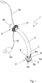
- an inner cannula 1 according to an embodiment of the present invention is shown in a perspective view.
- the inner cannula 1 has an arcuately curved tube 2 with a proximal end 3 and a distal end 4.
- a proximal opening 3 a is arranged at the proximal end 3 and a distal opening 4 a is arranged at the distal end 4.
- the tube 2 connecting the proximal opening 3a and the distal opening 4a is used to convey breathing gas.
- the proximal end 3 can be connected to a ventilation device for supplying breathing air, the proximal end 3 having a 15 mm connector 11 for this purpose.
- the distal end 4 is inserted into a patient's trachea through a tracheostoma.
- a cuff 5 is arranged on its outer circumference near the distal end 4 of the tube; more precisely, the cuff 5 is arranged in a ring section 6 which extends at least over the axial length of the cuff 5 and has a smaller outer diameter D TR than the outer diameter D TPC of the tube in the main section 7 located proximally in front of the cuff 5.
- the cuff 5 is a low-pressure cuff, the interior of which can be acted upon with a fluid, so that the cuff 5 can be completely unfolded and placed against the inner wall of a patient's trachea.
- the cuff 5 is connected to a control balloon with a filling valve 20 via a fluid line 19.
- the fluid is preferably air.
- the cuff 5 has a maximum axial extension of 5 mm to 30 mm.
- the cuff 5 has a distal section 5 b which, in a state in which the cuff 5 is completely filled, tapers in the direction of the distal end 4 of the tube 2.
- the radially tapering section 5b prevents or makes it more difficult for the distal tube opening to be blocked by a largely deflated cuff.
- the cuff 5 does not directly adjoin the free distal end 4 of the tube 2, but has an axial distance between the distal attachment point of the cuff 5 and the free distal end 4 of the tube 2.
- the axial distance is between 1 mm and 10 mm in size and is also intended to prevent the cuff 5 in its deflated state from being placed in front of the distal opening 4 of the tube 2 of the inner cannula 1 when the inner cannula 1 is withdrawn from the tube of an outer cannula.
- the proximal section 5a of the cuff 5 has a plate shape, with secretion from the subglottic on the section extending radially approximately perpendicular to the longitudinal axis in a state in which the inner cannula 1 is inserted into a trachea and the cuff 5 is completely filled Space the trachea can collect. Any secretion that may have accumulated can be sucked off through a suction opening 8.
- the suction opening 8 is arranged proximal to the cuff 5 within the ring section 6 and is connected to a suction line 8a.
- the suction line 8a is integrated into the wall of the tube 2 and merges at the proximal end 3 of the tube 2 into a tube extension 8b.
- the hose extension 8b can be connected to a suction device not shown here.
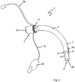
- Figure 2 is the inner cannula 1 according to the embodiment from FIG Figure 1 shown in a state in which the cuff 5 is deflated and placed on the outer circumference of the ring section 6.
- the cuff 5 indicated by a dashed line does not protrude beyond the radial outer circumference of the main section 7 of the tube 2 located proximally in front of the cuff 5, with the exception of thin and thus flexible folds of the cuff 5.
- the cuff 5 does not interfere with the insertion of the tube 2 of the inner cannula 1 into a tube of an outer cannula, because the thin folds of the cuff 5 nestle against the inner cannula wall of the ring section 6 or the already tight-fitting cuff material.
- the Figure 3 shows the previously related to the Figures 1 and 2 inner cannula 1 described in a state in which the inner cannula 1 is inserted into the tube 14 of an outer cannula 13.
- the embodiment referred to as a device for breathing air supply 12 consists of the previously described inner cannula 1 and an outer cannula 13.
- the outer cannula 13 has an arcuately curved tube 14 with a proximal end 15 and a distal end 16.
- the proximal end 15 has a proximal opening 15a and the distal end 16 has a distal opening 16a.
- the tube 2 of the inner cannula 1 is longer than the tube 14 of the outer cannula 13 and is dimensioned in such a way that after the introduction of the inner cannula 1 with its ring section 6 with the cuff 5 it protrudes beyond the distal end 16 of the outer cannula 13, the proximal end also The end of the inner cannula 1 still protrudes from the proximal end of the outer cannula 13.
- the suction opening 8 arranged in the ring section 6 is also exposed beyond the distal end 16 of the outer cannula 12.
- the outer diameter D TPC of the main section 7 of the tube 2 of the inner cannula 1 arranged proximally in front of the ring section 6 is slightly smaller than the inner diameter D AT of the tube 14 of the outer cannula 13.
- the outer surface of the section 7 accordingly rests against the inner surface of the tube 14 with little play, preferably 0.1 mm ⁇ diameter difference ⁇ 0.5 mm.
- the inner cannula 1 is detachably attached to the outer cannula 13.
- the inner cannula 1 has fastening means 17 at the proximal end 3 of the tube 2, as shown in FIG Figure 1 are shown.
- the outer cannula 13 also has a cannula shield 21 and a cuff 18.
- the cuff 18 is a fillable low-pressure cuff which is arranged on the outer circumference of the tube 14 of the outer cannula 13.
- the cuff 18 is connected by a fluid line 19 to a control balloon with a filling valve 20. In its filled state, the cuff 18 rests against the inner wall of the trachea of a patient and seals the outer cannula 13 from the trachea.
Landscapes
- Health & Medical Sciences (AREA)
- Pulmonology (AREA)
- Emergency Medicine (AREA)
- Engineering & Computer Science (AREA)
- Anesthesiology (AREA)
- Biomedical Technology (AREA)
- Heart & Thoracic Surgery (AREA)
- Hematology (AREA)
- Life Sciences & Earth Sciences (AREA)
- Animal Behavior & Ethology (AREA)
- General Health & Medical Sciences (AREA)
- Public Health (AREA)
- Veterinary Medicine (AREA)
- Media Introduction/Drainage Providing Device (AREA)
Claims (14)
- Canule de trachéotomie (1) comportant un tube (2) qui présente une extrémité proximale (3) dotée d'une ouverture proximale (3a) et une extrémité distale (4) dotée d'une ouverture distale (4a) ainsi qu'un ballonnet (5) agencé sur sa circonférence extérieure à proximité de l'extrémité distale (4), le tube (2) présentant à son extrémité distale (4a) une section annulaire effilée (6) s'étendant au moins sur la longueur axiale du ballonnet (5), dont le diamètre extérieur DTR est inférieur au diamètre extérieur du tube DTPC dans la section principale (7) située du côté proximal avant la section annulaire (6), et la différence de diamètre entre la section annulaire dans la zone du ballonnet (5) qui y est attachée et la section principale étant telle que la circonférence extérieure du ballonnet (5) dans un état vide et appliqué à la circonférence extérieure du tube (2) ne dépasse pas de la circonférence extérieure du tube (2) dans la section principale (7) située du côté proximal avant la section annulaire (6), caractérisée en ce que la section annulaire (6) avec le diamètre extérieur DTR plus petit présente une ouverture d'aspiration (8) qui est agencée du côté proximal par rapport au ballonnet (5) à la circonférence extérieure du tube (2).
- Canule de trachéotomie (1) selon la revendication 1, caractérisée en ce que la longueur de la section annulaire effilée (6) correspond au moins à la longueur du ballonnet et représente moins d'un tiers de la longueur du tube et l'extrémité proximale du ballonnet étant espacée de l'extrémité proximale du tube d'au moins deux tiers de la longueur de tube.
- Canule de trachéotomie (1) selon la revendication 1 ou 2, caractérisée en ce que la section annulaire (6) présente de préférence dans la zone de l'ouverture d'aspiration (8) une transition en gradins (9) entre les diamètres extérieurs DTR et DTPC.
- Canule de trachéotomie (1) selon l'une quelconque des revendications précédentes, caractérisée en ce que l'ouverture d'aspiration (8) est reliée à une conduite d'aspiration (8a), la conduite d'aspiration (8a) étant collée au tube (2) ou étant intégrée dans la paroi du tube (2).
- Canule de trachéotomie (1) selon l'une quelconque des revendications précédentes, caractérisée en ce que le ballonnet (5), dans son état rempli, présente une extension axiale maximum de 5 mm à 30 mm, de préférence de 10 mm à 20 mm.
- Canule de trachéotomie (1) selon l'une des revendications précédentes, caractérisée en ce que le ballonnet (5) présente une section proximale (5a) dont le diamètre extérieur rétrécit vers le côté proximal lorsque le ballonnet (5) est rempli, et/ou le ballonnet (5) présente une section distale (5b) dont le diamètre extérieur rétrécit vers le côté distal lorsque le ballonnet (5) est rempli.
- Canule de trachéotomie (1) selon l'une quelconque des revendications précédentes, caractérisée en ce que la distance entre l'extrémité distale libre (4) du tube et le point de départ distal (10a) du ballonnet (5) est comprise entre 1 mm et 10 mm, de préférence entre 5 mm et 10 mm.
- Canule de trachéotomie (1) selon l'une quelconque des revendications précédentes, caractérisée en ce que la distance entre l'extrémité distale libre (4) du tube et le point de départ proximal (10b) du ballonnet (5) est comprise entre 15 mm et 40 mm.
- Canule de trachéotomie (1) selon l'une quelconque des revendications précédentes, caractérisée en ce que la circonférence extérieure du tube (2) présente à son extrémité proximale (3) un diamètre extérieur DTP qui est supérieur au diamètre extérieur du tube DTPC proximal à la section annulaire (6), le diamètre extérieur DTP étant de préférence au moins 5 % et au maximum 20 %, de préférence d'environ 10 %, supérieur au diamètre extérieur DTPC.
- Canule de trachéotomie (1) selon l'une quelconque des revendications précédentes, caractérisée en ce que l'extrémité proximale (3) du tube (2) ne présente pas de protection de canule et/ou l'extrémité proximale (3) du tube (2) présente un connecteur (11) de 15 mm.
- Canule de trachéotomie (1) selon l'une quelconque des revendications précédentes, caractérisée en ce que la canule de trachéotomie (1) présente une articulation qui relie l'extrémité proximale (3) et l'extrémité distale (4) du tube (2) l'une à l'autre et permet au moins une mobilité limitée, en particulier une possibilité de pivotement de l'axe de l'extrémité distale (4) par rapport à l'axe de l'extrémité proximale (3).
- Dispositif d'alimentation en air respirable (12), en particulier tube endotrachéal ou canule de trachéotomie, constitué d'une canule interne (1) et d'une canule externe (13) comportant un tube (14), le tube (14) de la canule externe (13) présentant une extrémité proximale (15) dotée d'une ouverture proximale (15a) et une extrémité distale (16) dotée d'une ouverture distale (16a), caractérisé en ce que la canule interne (1) est une canule de trachéotomie (1) selon l'une des revendications 1 à 11, le tube (2) de la canule interne (1) étant dimensionné et conçu pour être inséré dans le tube (14) de la canule externe (13) de manière telle que la section annulaire (6) de la canule interne (1) avec le ballonnet (5) dépasse de l'extrémité distale (16) de la canule externe (13).
- Dispositif d'alimentation en air respirable (12) selon la revendication 12, caractérisé en ce que la canule interne (1) et/ou la canule externe (13) présente(nt) des moyens (17) de fixation amovible de l'une à l'autre, et/ou le tube (14) de la canule externe (13) présente un ballonnet (18) sur sa circonférence extérieure.
- Dispositif d'alimentation en air respirable (12) selon l'une quelconque des revendications 13 ou 14, caractérisé en ce que le tube (14) de la canule externe (13) présente un diamètre intérieur DAT qui constitue la suite du diamètre extérieur du tube (2) DTPC de la canule interne (1) du côté proximal de la section annulaire (6).
Applications Claiming Priority (2)
| Application Number | Priority Date | Filing Date | Title |
|---|---|---|---|
| DE102016120821.3A DE102016120821A1 (de) | 2016-11-02 | 2016-11-02 | Tracheostomiekanüle |
| PCT/EP2017/077259 WO2018082980A1 (fr) | 2016-11-02 | 2017-10-25 | Canule de trachéotomie |
Publications (2)
| Publication Number | Publication Date |
|---|---|
| EP3535002A1 EP3535002A1 (fr) | 2019-09-11 |
| EP3535002B1 true EP3535002B1 (fr) | 2021-02-17 |
Family
ID=60164721
Family Applications (1)
| Application Number | Title | Priority Date | Filing Date |
|---|---|---|---|
| EP17788235.4A Active EP3535002B1 (fr) | 2016-11-02 | 2017-10-25 | Canule de trachéotomie |
Country Status (3)
| Country | Link |
|---|---|
| EP (1) | EP3535002B1 (fr) |
| DE (1) | DE102016120821A1 (fr) |
| WO (1) | WO2018082980A1 (fr) |
Families Citing this family (2)
| Publication number | Priority date | Publication date | Assignee | Title |
|---|---|---|---|---|
| US11684737B2 (en) * | 2018-07-26 | 2023-06-27 | Aninimed Llc | Endotracheal tube exchange |
| CN112386775B (zh) * | 2020-11-03 | 2022-11-22 | 中山市人民医院 | 气管插管器 |
Family Cites Families (8)
| Publication number | Priority date | Publication date | Assignee | Title |
|---|---|---|---|---|
| US5389074A (en) * | 1993-10-27 | 1995-02-14 | The Regents Of The University Of California | Body insertion tube with anesthetic jacket |
| GB2324735B (en) * | 1997-04-28 | 2001-06-20 | George Downward | A device to seal the trachea in the intubated patient |
| US7201168B2 (en) * | 2004-04-14 | 2007-04-10 | King Systems Corporation | Non-tracheal ventilation tube |
| GB0411858D0 (en) * | 2004-05-27 | 2004-06-30 | Young Peter J | Device to facilitate airway suctioning |
| GB0719054D0 (en) * | 2007-09-29 | 2007-11-07 | Nasir Muhammed A | Airway device |
| US20130000649A1 (en) * | 2011-06-29 | 2013-01-03 | Nellcor Puritan Bennett Llc | Tracheal tube with controlled-profile cuff |
| US9089663B2 (en) * | 2012-06-28 | 2015-07-28 | Cook Medical Technologies Llc | Percutaneous access device |
| EP2801384A1 (fr) * | 2013-05-10 | 2014-11-12 | Universität Zürich | Tube pour intubation endobronchique |
-
2016
- 2016-11-02 DE DE102016120821.3A patent/DE102016120821A1/de active Pending
-
2017
- 2017-10-25 EP EP17788235.4A patent/EP3535002B1/fr active Active
- 2017-10-25 WO PCT/EP2017/077259 patent/WO2018082980A1/fr unknown
Non-Patent Citations (1)
| Title |
|---|
| None * |
Also Published As
| Publication number | Publication date |
|---|---|
| EP3535002A1 (fr) | 2019-09-11 |
| WO2018082980A1 (fr) | 2018-05-11 |
| DE102016120821A1 (de) | 2018-05-03 |
Similar Documents
| Publication | Publication Date | Title |
|---|---|---|
| DE19510783C2 (de) | Tracheostomietubus | |
| EP2032052B1 (fr) | Dispositif permettant l'insertion d'une canule trachéale dans un trachéostome | |
| EP1744718B1 (fr) | Sonde destinee a l'alimentation enterale et systeme sonde destinee a l'alimentation enterale et la decompression gastrique ou drainage | |
| DE112010004298B4 (de) | Vorrichtung zum absaugen des sputums bei tracheotomie-patienten sowie innenkanüle für eine trachealkanüle | |
| EP2046431B1 (fr) | Canule de tracheotomie avec canule interne | |
| EP2322240B1 (fr) | Canule de trachéotomie dotée d'une fenêtre | |
| EP3535002B1 (fr) | Canule de trachéotomie | |
| DE102018123562B4 (de) | Beatmungsvorrichtung | |
| EP0138089B1 (fr) | Bougie | |
| EP3535004B1 (fr) | Canule trachéale dotée d'un dispositif d'étanchéité | |
| EP3535003B1 (fr) | Dispositif de respiration artificielle trachéale souple | |
| EP3787722B1 (fr) | Dispositif de respiration trachéale doté d'une étanchéité | |
| WO2017108712A1 (fr) | Élément d'aide à l'introduction | |
| EP3858413A1 (fr) | Unité de liaison courbée destinée à la liaison d'une unité d'accouplement du côté d'un patient à un appareil médical | |
| DE102014109001A1 (de) | Trachealbeatmungsvorrichtung | |
| EP3727538B1 (fr) | Canule de trachéotomie comportant une ouverture de phonation | |
| DE3223592A1 (de) | Einstellbare rohrschelle | |
| WO2005023360A1 (fr) | Raccord de tuyaux enfichable | |
| WO2021233784A1 (fr) | Dispositif respiratoire | |
| DE2322506C3 (de) | Verwendung eines speziellen SiIi- , conkautschuks für die Manschette eines Katheters | |
| WO2024088454A1 (fr) | Canule de trachéotomie | |
| DE202007016753U1 (de) | Kanüle für die perkutane Tracheotomie mit drehbarem und auswechselbarem Konnektor |
Legal Events
| Date | Code | Title | Description |
|---|---|---|---|
| STAA | Information on the status of an ep patent application or granted ep patent |
Free format text: STATUS: UNKNOWN |
|
| STAA | Information on the status of an ep patent application or granted ep patent |
Free format text: STATUS: THE INTERNATIONAL PUBLICATION HAS BEEN MADE |
|
| PUAI | Public reference made under article 153(3) epc to a published international application that has entered the european phase |
Free format text: ORIGINAL CODE: 0009012 |
|
| STAA | Information on the status of an ep patent application or granted ep patent |
Free format text: STATUS: REQUEST FOR EXAMINATION WAS MADE |
|
| 17P | Request for examination filed |
Effective date: 20190529 |
|
| AK | Designated contracting states |
Kind code of ref document: A1 Designated state(s): AL AT BE BG CH CY CZ DE DK EE ES FI FR GB GR HR HU IE IS IT LI LT LU LV MC MK MT NL NO PL PT RO RS SE SI SK SM TR |
|
| AX | Request for extension of the european patent |
Extension state: BA ME |
|
| DAV | Request for validation of the european patent (deleted) | ||
| DAX | Request for extension of the european patent (deleted) | ||
| GRAP | Despatch of communication of intention to grant a patent |
Free format text: ORIGINAL CODE: EPIDOSNIGR1 |
|
| STAA | Information on the status of an ep patent application or granted ep patent |
Free format text: STATUS: GRANT OF PATENT IS INTENDED |
|
| INTG | Intention to grant announced |
Effective date: 20201204 |
|
| GRAS | Grant fee paid |
Free format text: ORIGINAL CODE: EPIDOSNIGR3 |
|
| GRAA | (expected) grant |
Free format text: ORIGINAL CODE: 0009210 |
|
| STAA | Information on the status of an ep patent application or granted ep patent |
Free format text: STATUS: THE PATENT HAS BEEN GRANTED |
|
| AK | Designated contracting states |
Kind code of ref document: B1 Designated state(s): AL AT BE BG CH CY CZ DE DK EE ES FI FR GB GR HR HU IE IS IT LI LT LU LV MC MK MT NL NO PL PT RO RS SE SI SK SM TR |
|
| REG | Reference to a national code |
Ref country code: GB Ref legal event code: FG4D Free format text: NOT ENGLISH |
|
| REG | Reference to a national code |
Ref country code: CH Ref legal event code: EP |
|
| REG | Reference to a national code |
Ref country code: DE Ref legal event code: R096 Ref document number: 502017009382 Country of ref document: DE |
|
| REG | Reference to a national code |
Ref country code: AT Ref legal event code: REF Ref document number: 1360654 Country of ref document: AT Kind code of ref document: T Effective date: 20210315 |
|
| REG | Reference to a national code |
Ref country code: IE Ref legal event code: FG4D Free format text: LANGUAGE OF EP DOCUMENT: GERMAN |
|
| REG | Reference to a national code |
Ref country code: LT Ref legal event code: MG9D |
|
| REG | Reference to a national code |
Ref country code: NL Ref legal event code: MP Effective date: 20210217 |
|
| PG25 | Lapsed in a contracting state [announced via postgrant information from national office to epo] |
Ref country code: NO Free format text: LAPSE BECAUSE OF FAILURE TO SUBMIT A TRANSLATION OF THE DESCRIPTION OR TO PAY THE FEE WITHIN THE PRESCRIBED TIME-LIMIT Effective date: 20210517 Ref country code: PT Free format text: LAPSE BECAUSE OF FAILURE TO SUBMIT A TRANSLATION OF THE DESCRIPTION OR TO PAY THE FEE WITHIN THE PRESCRIBED TIME-LIMIT Effective date: 20210617 Ref country code: FI Free format text: LAPSE BECAUSE OF FAILURE TO SUBMIT A TRANSLATION OF THE DESCRIPTION OR TO PAY THE FEE WITHIN THE PRESCRIBED TIME-LIMIT Effective date: 20210217 Ref country code: HR Free format text: LAPSE BECAUSE OF FAILURE TO SUBMIT A TRANSLATION OF THE DESCRIPTION OR TO PAY THE FEE WITHIN THE PRESCRIBED TIME-LIMIT Effective date: 20210217 Ref country code: GR Free format text: LAPSE BECAUSE OF FAILURE TO SUBMIT A TRANSLATION OF THE DESCRIPTION OR TO PAY THE FEE WITHIN THE PRESCRIBED TIME-LIMIT Effective date: 20210518 Ref country code: BG Free format text: LAPSE BECAUSE OF FAILURE TO SUBMIT A TRANSLATION OF THE DESCRIPTION OR TO PAY THE FEE WITHIN THE PRESCRIBED TIME-LIMIT Effective date: 20210517 Ref country code: LT Free format text: LAPSE BECAUSE OF FAILURE TO SUBMIT A TRANSLATION OF THE DESCRIPTION OR TO PAY THE FEE WITHIN THE PRESCRIBED TIME-LIMIT Effective date: 20210217 |
|
| PG25 | Lapsed in a contracting state [announced via postgrant information from national office to epo] |
Ref country code: LV Free format text: LAPSE BECAUSE OF FAILURE TO SUBMIT A TRANSLATION OF THE DESCRIPTION OR TO PAY THE FEE WITHIN THE PRESCRIBED TIME-LIMIT Effective date: 20210217 Ref country code: NL Free format text: LAPSE BECAUSE OF FAILURE TO SUBMIT A TRANSLATION OF THE DESCRIPTION OR TO PAY THE FEE WITHIN THE PRESCRIBED TIME-LIMIT Effective date: 20210217 Ref country code: PL Free format text: LAPSE BECAUSE OF FAILURE TO SUBMIT A TRANSLATION OF THE DESCRIPTION OR TO PAY THE FEE WITHIN THE PRESCRIBED TIME-LIMIT Effective date: 20210217 Ref country code: RS Free format text: LAPSE BECAUSE OF FAILURE TO SUBMIT A TRANSLATION OF THE DESCRIPTION OR TO PAY THE FEE WITHIN THE PRESCRIBED TIME-LIMIT Effective date: 20210217 Ref country code: SE Free format text: LAPSE BECAUSE OF FAILURE TO SUBMIT A TRANSLATION OF THE DESCRIPTION OR TO PAY THE FEE WITHIN THE PRESCRIBED TIME-LIMIT Effective date: 20210217 |
|
| PG25 | Lapsed in a contracting state [announced via postgrant information from national office to epo] |
Ref country code: IS Free format text: LAPSE BECAUSE OF FAILURE TO SUBMIT A TRANSLATION OF THE DESCRIPTION OR TO PAY THE FEE WITHIN THE PRESCRIBED TIME-LIMIT Effective date: 20210617 |
|
| PG25 | Lapsed in a contracting state [announced via postgrant information from national office to epo] |
Ref country code: SM Free format text: LAPSE BECAUSE OF FAILURE TO SUBMIT A TRANSLATION OF THE DESCRIPTION OR TO PAY THE FEE WITHIN THE PRESCRIBED TIME-LIMIT Effective date: 20210217 Ref country code: EE Free format text: LAPSE BECAUSE OF FAILURE TO SUBMIT A TRANSLATION OF THE DESCRIPTION OR TO PAY THE FEE WITHIN THE PRESCRIBED TIME-LIMIT Effective date: 20210217 Ref country code: CZ Free format text: LAPSE BECAUSE OF FAILURE TO SUBMIT A TRANSLATION OF THE DESCRIPTION OR TO PAY THE FEE WITHIN THE PRESCRIBED TIME-LIMIT Effective date: 20210217 |
|
| REG | Reference to a national code |
Ref country code: DE Ref legal event code: R097 Ref document number: 502017009382 Country of ref document: DE |
|
| PG25 | Lapsed in a contracting state [announced via postgrant information from national office to epo] |
Ref country code: DK Free format text: LAPSE BECAUSE OF FAILURE TO SUBMIT A TRANSLATION OF THE DESCRIPTION OR TO PAY THE FEE WITHIN THE PRESCRIBED TIME-LIMIT Effective date: 20210217 Ref country code: SK Free format text: LAPSE BECAUSE OF FAILURE TO SUBMIT A TRANSLATION OF THE DESCRIPTION OR TO PAY THE FEE WITHIN THE PRESCRIBED TIME-LIMIT Effective date: 20210217 Ref country code: RO Free format text: LAPSE BECAUSE OF FAILURE TO SUBMIT A TRANSLATION OF THE DESCRIPTION OR TO PAY THE FEE WITHIN THE PRESCRIBED TIME-LIMIT Effective date: 20210217 |
|
| PLBE | No opposition filed within time limit |
Free format text: ORIGINAL CODE: 0009261 |
|
| STAA | Information on the status of an ep patent application or granted ep patent |
Free format text: STATUS: NO OPPOSITION FILED WITHIN TIME LIMIT |
|
| 26N | No opposition filed |
Effective date: 20211118 |
|
| PG25 | Lapsed in a contracting state [announced via postgrant information from national office to epo] |
Ref country code: AL Free format text: LAPSE BECAUSE OF FAILURE TO SUBMIT A TRANSLATION OF THE DESCRIPTION OR TO PAY THE FEE WITHIN THE PRESCRIBED TIME-LIMIT Effective date: 20210217 Ref country code: ES Free format text: LAPSE BECAUSE OF FAILURE TO SUBMIT A TRANSLATION OF THE DESCRIPTION OR TO PAY THE FEE WITHIN THE PRESCRIBED TIME-LIMIT Effective date: 20210217 |
|
| PG25 | Lapsed in a contracting state [announced via postgrant information from national office to epo] |
Ref country code: SI Free format text: LAPSE BECAUSE OF FAILURE TO SUBMIT A TRANSLATION OF THE DESCRIPTION OR TO PAY THE FEE WITHIN THE PRESCRIBED TIME-LIMIT Effective date: 20210217 |
|
| PG25 | Lapsed in a contracting state [announced via postgrant information from national office to epo] |
Ref country code: IT Free format text: LAPSE BECAUSE OF FAILURE TO SUBMIT A TRANSLATION OF THE DESCRIPTION OR TO PAY THE FEE WITHIN THE PRESCRIBED TIME-LIMIT Effective date: 20210217 |
|
| REG | Reference to a national code |
Ref country code: CH Ref legal event code: PL |
|
| PG25 | Lapsed in a contracting state [announced via postgrant information from national office to epo] |
Ref country code: IS Free format text: LAPSE BECAUSE OF FAILURE TO SUBMIT A TRANSLATION OF THE DESCRIPTION OR TO PAY THE FEE WITHIN THE PRESCRIBED TIME-LIMIT Effective date: 20210617 |
|
| REG | Reference to a national code |
Ref country code: BE Ref legal event code: MM Effective date: 20211031 |
|
| PG25 | Lapsed in a contracting state [announced via postgrant information from national office to epo] |
Ref country code: MC Free format text: LAPSE BECAUSE OF FAILURE TO SUBMIT A TRANSLATION OF THE DESCRIPTION OR TO PAY THE FEE WITHIN THE PRESCRIBED TIME-LIMIT Effective date: 20210217 |
|
| PG25 | Lapsed in a contracting state [announced via postgrant information from national office to epo] |
Ref country code: LU Free format text: LAPSE BECAUSE OF NON-PAYMENT OF DUE FEES Effective date: 20211025 Ref country code: BE Free format text: LAPSE BECAUSE OF NON-PAYMENT OF DUE FEES Effective date: 20211031 |
|
| PG25 | Lapsed in a contracting state [announced via postgrant information from national office to epo] |
Ref country code: LI Free format text: LAPSE BECAUSE OF NON-PAYMENT OF DUE FEES Effective date: 20211031 Ref country code: CH Free format text: LAPSE BECAUSE OF NON-PAYMENT OF DUE FEES Effective date: 20211031 |
|
| PG25 | Lapsed in a contracting state [announced via postgrant information from national office to epo] |
Ref country code: FR Free format text: LAPSE BECAUSE OF NON-PAYMENT OF DUE FEES Effective date: 20211031 |
|
| REG | Reference to a national code |
Ref country code: DE Ref legal event code: R081 Ref document number: 502017009382 Country of ref document: DE Owner name: COLOPLAST A/S, DK Free format text: FORMER OWNER: TRACOE MEDICAL GMBH, 55268 NIEDER-OLM, DE |
|
| PG25 | Lapsed in a contracting state [announced via postgrant information from national office to epo] |
Ref country code: CY Free format text: LAPSE BECAUSE OF FAILURE TO SUBMIT A TRANSLATION OF THE DESCRIPTION OR TO PAY THE FEE WITHIN THE PRESCRIBED TIME-LIMIT Effective date: 20210217 |
|
| PG25 | Lapsed in a contracting state [announced via postgrant information from national office to epo] |
Ref country code: HU Free format text: LAPSE BECAUSE OF FAILURE TO SUBMIT A TRANSLATION OF THE DESCRIPTION OR TO PAY THE FEE WITHIN THE PRESCRIBED TIME-LIMIT; INVALID AB INITIO Effective date: 20171025 |
|
| REG | Reference to a national code |
Ref country code: AT Ref legal event code: MM01 Ref document number: 1360654 Country of ref document: AT Kind code of ref document: T Effective date: 20221025 |
|
| REG | Reference to a national code |
Ref country code: GB Ref legal event code: 732E Free format text: REGISTERED BETWEEN 20231214 AND 20231220 |
|
| PGFP | Annual fee paid to national office [announced via postgrant information from national office to epo] |
Ref country code: GB Payment date: 20231027 Year of fee payment: 7 |
|
| PG25 | Lapsed in a contracting state [announced via postgrant information from national office to epo] |
Ref country code: AT Free format text: LAPSE BECAUSE OF NON-PAYMENT OF DUE FEES Effective date: 20221025 |
|
| PGFP | Annual fee paid to national office [announced via postgrant information from national office to epo] |
Ref country code: TR Payment date: 20231006 Year of fee payment: 7 Ref country code: IE Payment date: 20231027 Year of fee payment: 7 Ref country code: DE Payment date: 20231027 Year of fee payment: 7 |
|
| PG25 | Lapsed in a contracting state [announced via postgrant information from national office to epo] |
Ref country code: MK Free format text: LAPSE BECAUSE OF FAILURE TO SUBMIT A TRANSLATION OF THE DESCRIPTION OR TO PAY THE FEE WITHIN THE PRESCRIBED TIME-LIMIT Effective date: 20210217 |