EP3535002B1 - Tracheostomy cannula - Google Patents
Tracheostomy cannula Download PDFInfo
- Publication number
- EP3535002B1 EP3535002B1 EP17788235.4A EP17788235A EP3535002B1 EP 3535002 B1 EP3535002 B1 EP 3535002B1 EP 17788235 A EP17788235 A EP 17788235A EP 3535002 B1 EP3535002 B1 EP 3535002B1
- Authority
- EP
- European Patent Office
- Prior art keywords
- tube
- cannula
- cuff
- proximal
- section
- Prior art date
- Legal status (The legal status is an assumption and is not a legal conclusion. Google has not performed a legal analysis and makes no representation as to the accuracy of the status listed.)
- Active
Links
- 230000004323 axial length Effects 0.000 claims description 6
- 230000007704 transition Effects 0.000 claims description 6
- 230000000241 respiratory effect Effects 0.000 claims description 5
- GUJDUXMBBAOBHN-UHFFFAOYSA-N 6-(dimethylamino)-n-(2h-tetrazol-5-yl)pyrazine-2-carboxamide Chemical compound CN(C)C1=CN=CC(C(=O)NC2=NNN=N2)=N1 GUJDUXMBBAOBHN-UHFFFAOYSA-N 0.000 claims 5
- 210000003437 trachea Anatomy 0.000 description 43
- 230000029058 respiratory gaseous exchange Effects 0.000 description 22
- 230000028327 secretion Effects 0.000 description 15
- 239000007789 gas Substances 0.000 description 9
- 238000009423 ventilation Methods 0.000 description 8
- 239000012530 fluid Substances 0.000 description 7
- 241001631457 Cannula Species 0.000 description 5
- 230000006378 damage Effects 0.000 description 5
- 239000000463 material Substances 0.000 description 5
- 210000000621 bronchi Anatomy 0.000 description 4
- 238000003780 insertion Methods 0.000 description 4
- 230000037431 insertion Effects 0.000 description 4
- 210000004072 lung Anatomy 0.000 description 4
- 238000007789 sealing Methods 0.000 description 4
- 230000008859 change Effects 0.000 description 3
- 230000009747 swallowing Effects 0.000 description 3
- 238000005452 bending Methods 0.000 description 2
- 230000007774 longterm Effects 0.000 description 2
- 238000000034 method Methods 0.000 description 2
- 238000003825 pressing Methods 0.000 description 2
- 230000008569 process Effects 0.000 description 2
- 230000035939 shock Effects 0.000 description 2
- 241000894006 Bacteria Species 0.000 description 1
- 206010035664 Pneumonia Diseases 0.000 description 1
- 239000006096 absorbing agent Substances 0.000 description 1
- 238000004026 adhesive bonding Methods 0.000 description 1
- QVGXLLKOCUKJST-UHFFFAOYSA-N atomic oxygen Chemical compound [O] QVGXLLKOCUKJST-UHFFFAOYSA-N 0.000 description 1
- 230000006835 compression Effects 0.000 description 1
- 238000007906 compression Methods 0.000 description 1
- 230000008602 contraction Effects 0.000 description 1
- 230000007423 decrease Effects 0.000 description 1
- 230000003247 decreasing effect Effects 0.000 description 1
- 230000001771 impaired effect Effects 0.000 description 1
- 238000001746 injection moulding Methods 0.000 description 1
- 210000000867 larynx Anatomy 0.000 description 1
- 238000011866 long-term treatment Methods 0.000 description 1
- 238000012986 modification Methods 0.000 description 1
- 230000004048 modification Effects 0.000 description 1
- 210000004400 mucous membrane Anatomy 0.000 description 1
- 239000001301 oxygen Substances 0.000 description 1
- 229910052760 oxygen Inorganic materials 0.000 description 1
- 210000002345 respiratory system Anatomy 0.000 description 1
- 230000000284 resting effect Effects 0.000 description 1
- 238000011282 treatment Methods 0.000 description 1
- 238000003466 welding Methods 0.000 description 1
Images

Classifications
-
- A—HUMAN NECESSITIES
- A61—MEDICAL OR VETERINARY SCIENCE; HYGIENE
- A61M—DEVICES FOR INTRODUCING MEDIA INTO, OR ONTO, THE BODY; DEVICES FOR TRANSDUCING BODY MEDIA OR FOR TAKING MEDIA FROM THE BODY; DEVICES FOR PRODUCING OR ENDING SLEEP OR STUPOR
- A61M16/00—Devices for influencing the respiratory system of patients by gas treatment, e.g. mouth-to-mouth respiration; Tracheal tubes
- A61M16/04—Tracheal tubes
- A61M16/0465—Tracheostomy tubes; Devices for performing a tracheostomy; Accessories therefor, e.g. masks, filters
-
- A—HUMAN NECESSITIES
- A61—MEDICAL OR VETERINARY SCIENCE; HYGIENE
- A61M—DEVICES FOR INTRODUCING MEDIA INTO, OR ONTO, THE BODY; DEVICES FOR TRANSDUCING BODY MEDIA OR FOR TAKING MEDIA FROM THE BODY; DEVICES FOR PRODUCING OR ENDING SLEEP OR STUPOR
- A61M16/00—Devices for influencing the respiratory system of patients by gas treatment, e.g. mouth-to-mouth respiration; Tracheal tubes
- A61M16/04—Tracheal tubes
- A61M16/0402—Special features for tracheal tubes not otherwise provided for
- A61M16/0418—Special features for tracheal tubes not otherwise provided for with integrated means for changing the degree of curvature, e.g. for easy intubation
-
- A—HUMAN NECESSITIES
- A61—MEDICAL OR VETERINARY SCIENCE; HYGIENE
- A61M—DEVICES FOR INTRODUCING MEDIA INTO, OR ONTO, THE BODY; DEVICES FOR TRANSDUCING BODY MEDIA OR FOR TAKING MEDIA FROM THE BODY; DEVICES FOR PRODUCING OR ENDING SLEEP OR STUPOR
- A61M16/00—Devices for influencing the respiratory system of patients by gas treatment, e.g. mouth-to-mouth respiration; Tracheal tubes
- A61M16/04—Tracheal tubes
- A61M16/0402—Special features for tracheal tubes not otherwise provided for
- A61M16/0427—Special features for tracheal tubes not otherwise provided for with removable and re-insertable liner tubes, e.g. for cleaning
-
- A—HUMAN NECESSITIES
- A61—MEDICAL OR VETERINARY SCIENCE; HYGIENE
- A61M—DEVICES FOR INTRODUCING MEDIA INTO, OR ONTO, THE BODY; DEVICES FOR TRANSDUCING BODY MEDIA OR FOR TAKING MEDIA FROM THE BODY; DEVICES FOR PRODUCING OR ENDING SLEEP OR STUPOR
- A61M16/00—Devices for influencing the respiratory system of patients by gas treatment, e.g. mouth-to-mouth respiration; Tracheal tubes
- A61M16/04—Tracheal tubes
- A61M16/0402—Special features for tracheal tubes not otherwise provided for
- A61M16/0431—Special features for tracheal tubes not otherwise provided for with a cross-sectional shape other than circular
-
- A—HUMAN NECESSITIES
- A61—MEDICAL OR VETERINARY SCIENCE; HYGIENE
- A61M—DEVICES FOR INTRODUCING MEDIA INTO, OR ONTO, THE BODY; DEVICES FOR TRANSDUCING BODY MEDIA OR FOR TAKING MEDIA FROM THE BODY; DEVICES FOR PRODUCING OR ENDING SLEEP OR STUPOR
- A61M16/00—Devices for influencing the respiratory system of patients by gas treatment, e.g. mouth-to-mouth respiration; Tracheal tubes
- A61M16/04—Tracheal tubes
- A61M16/0434—Cuffs
-
- A—HUMAN NECESSITIES
- A61—MEDICAL OR VETERINARY SCIENCE; HYGIENE
- A61M—DEVICES FOR INTRODUCING MEDIA INTO, OR ONTO, THE BODY; DEVICES FOR TRANSDUCING BODY MEDIA OR FOR TAKING MEDIA FROM THE BODY; DEVICES FOR PRODUCING OR ENDING SLEEP OR STUPOR
- A61M16/00—Devices for influencing the respiratory system of patients by gas treatment, e.g. mouth-to-mouth respiration; Tracheal tubes
- A61M16/04—Tracheal tubes
- A61M16/0465—Tracheostomy tubes; Devices for performing a tracheostomy; Accessories therefor, e.g. masks, filters
- A61M16/0472—Devices for performing a tracheostomy
Definitions
- the present invention relates to a tracheostomy cannula with a tube which has a proximal end with a proximal opening and a distal end with a distal opening and a cuff arranged on its outer circumference near the distal end.
- the tracheostomy cannula according to the invention is intended in particular for use as an inner cannula which can be inserted and passed through an existing tracheostomy cannula (outer cannula) so that the distal end of the inner cannula protrudes from the distal end of the outer cannula.
- the inner cannula can also be used on its own without the outer cannula, especially for short transition times.
- the present invention also relates to a device for supplying breathing air, in particular an endotracheal tube or tracheostomy tube, each consisting of an inner cannula and an outer cannula with a tube, the tube of the outer cannula having a proximal end with a proximal opening and a distal end with a distal opening .
- Tracheostomy cannulas are inserted into the trachea of a patient through an artificial access, the so-called tracheostoma, for the supply of breathing air.
- the proximal end of the arcuately curved tube can be connected outside of the patient's body to a ventilation device for supplying breathing air, while the distal end of the tracheostomy cannula opens inside the patient's trachea.
- the tube connecting the two ends is used to pass breathing gas through so that breathing gas can be introduced into the patient's lungs via the trachea or returned from the trachea.
- a tracheostomy tube For a reliable supply of oxygen or respiratory gas, it is important that the tube of a tracheostomy tube, the outer diameter of which is significantly smaller than the inner diameter of the trachea to avoid injuries, is sealed against the inner wall of the trachea and that as little or no respiratory gas as possible passes the tube and can flow back through the upper respiratory tract before it reaches the lungs.
- a so-called cuff inflatable cuff
- the initially empty cuff becomes filled with gas (e.g. air) and inflated.
- the cuff When inflated, the cuff rests against the inner wall of the trachea and seals the tube against the inner wall of the trachea. The cuff also prevents secretion from the subglottic space from passing the tube into the bronchi. Such secretions mostly contain bacteria which can lead to pneumonia during aspiration, which are a frequent complication in long-term ventilated patients.
- the tracheostomy cannula Since the tracheostomy cannula is usually intended for long-term ventilation, it should impair the patient as little as possible, should not damage the mucous membrane of the trachea and enable safe ventilation of the patient.
- the US 2008/0283052 A1 , the US 2014/0000627 A1 , the US 2010/0288289 A1 already show trascheostomy cannulas with an annular section that is tapered in the area of a cuff and that are arranged on the outside of a cannula tube.
- the tracheostomy tube is too big, too small, too short and / or too long for the patient to be treated, it can cause pain or even its function can be impaired.
- the tracheostomy tube must then be replaced with a better fitting tracheostomy tube.
- situations may arise in which the tracheostomy tube is damaged, contaminated, or needs to be replaced for other reasons.
- an object of the present invention is to provide a tracheostomy cannula which enables the cannula to be changed safely and at the same time significantly reduces the risk of secretion being aspirated.
- a tracheostomy cannula with the features of claim 1.
- the tube has near its distal end a tapered section with a reduced outer diameter which extends at least over the axial length of the cuff and which has a smaller outer diameter than the tube in the main section proximally in front of it, the length of the tapered section preferably being at least the Corresponds to the length of the cuff and is less than one third of the length of the tube and wherein the proximal end of the cuff is preferably at least two thirds of the tube length from the proximal end of the tube.
- the ring section with the smaller outer diameter D TR has a suction opening that is proximal from the cuff is arranged on the outer circumference of the tube (the inner cannula).
- the suction opening arranged proximally of the cuff is used to suction out secretions that may collect proximally in front of the cuff. This is particularly important when changing cannulas because the cuff is then moved and possibly deflated and the seal cannot be guaranteed consistently.
- the tracheostomy cannula according to the invention is intended to be inserted into a second tracheostomy cannula.
- the second tracheostomy cannula is also referred to as the outer cannula and the first, inner tracheostomy cannula is referred to as the inner cannula.
- the tracheostomy cannula can, however, also be used without further ado, in particular for a short time, on its own, the advantages of the tracheostomy cannula according to the invention being realized primarily in connection with an outer cannula.
- the section with reduced diameter can, for. B. be stepped off from the proximally in front of the section of the tube or designed as an at least partially conical tapering of the outside of the tube in the distal area.
- the purpose of the tapering is to accommodate the tightly fitting cuff in the unfilled state in such a way that the cannula, as an inner cannula, can be passed through an outer cannula together with the cuff fitted on the outside in the tapered section without damaging the cuff, the outer diameter being in the proximal area of the tube can correspond to the inner diameter of the outer cannula.
- the inner cannula including the deflated cuff and lying outside in the tapered area, therefore has a diameter in the tapered section which does not exceed the diameter of the main section in the proximal area.
- the inner cannula has z. B. on a tube, which is curved like an arc like the outer cannula.
- the inner cannula can, however, also be designed as a straight cannula which only assumes its curved shape when it is inserted through the outer cannula.
- the tube has a proximal end with a proximal opening and a distal end with a distal opening.
- the “distal end” of the respective cannula in the sense of the present invention denotes the end introduced into the trachea or insertable into the trachea, which is further away than the proximal end from the attending physician or medical personnel.
- the terms “distal” (remote) and “proximal” (near) are thus defined from the perspective of the person treating.
- the “proximal end” is intended for placement outside the body of a patient.
- the cuff arranged on the outer circumference near the distal end of the tube of the inner cannula is arranged on the other side of the distal end of the tube of the outer cannula in order to be able to seal against the inner wall of the trachea.
- the cuff is arranged "near the distal end of the tube” if the cuff is arranged within an axial end section of the tube which, measured from the distal end of the tube, extends over an axial section of the cuff Length is a maximum of three times and a minimum of simple of the inner diameter of the tube.
- the distance between the free distal end of the tube and the distal attachment point of the cuff is between 1 mm and 10 mm, preferably between 3 mm and 6 mm.
- the distance between the distal attachment point of the cuff and the free distal end of the tube is intended to prevent the cuff from being positioned in front of the distal opening of the tube of the inner cannula when the inner cannula is withdrawn from the tube of an outer cannula.
- the proximal attachment point of the cuff can, for example, be at a distance of 15 mm to 40 mm from the distal end of the tube.
- the diameter of the cuff which is measured perpendicular to the tube axis, is at least twice the inner diameter of the tube and at most four times.
- a cuff shape is preferred in which the cuff tapers conically in the direction of the distal end.
- the inner diameter of the tube of the outer cannula must necessarily be somewhat larger than the outer diameter of the tube of the inner cannula.
- the inner diameter of the tube of the outer cannula and the outer diameter of the tube of the inner cannula are matched to one another in such a way that the inner cannula can slide in the outer cannula with little resistance.
- the invention provides that the tube at its distal end has a section which extends at least over the axial length of the cuff and whose outer diameter D TR is smaller than the outer diameter of the tube D is TPC in the section located proximally in front of the ring section, which is hereinafter referred to as the main section, so that the empty cuff resting on the tapered section does not increase the overall diameter or does not increase the overall diameter significantly beyond the outer diameter of the tube outside the tapered section.
- the tapered section is also referred to below as a ring section, since it has a rotational symmetry, at least in preferred variants.
- the outer circumference of the cuff does not protrude beyond the outer circumference of the tube in the main section located proximally in front of the cuff in an empty state in which it is placed on the outer circumference of the tube.
- the cuff In its empty state and placed on the outer circumference of the tube, the cuff can be completely received in an annular space formed by the smaller outer diameter D TR .
- the cuff When the tube of the inner cannula is inserted into the tube of an outer cannula, the cuff is arranged in this way in the annular space and is protected from damage when it is inserted or passed through.
- the cuffs used preferably have a small wall thickness between 5 ⁇ m and 45 ⁇ m.
- the cuff When empty and placed on the outer circumference of the tube, the cuff generally still has folds that can protrude radially outward. These may have to be pressed onto the tube with little force (e.g. 0.03 N). When these folds are placed on the tube or the deflated cuff, the tube with the cuff fits easily into the corresponding outer cannula.
- the cuff is, for example, a high-volume, low-pressure cuff
- narrow folds of the cuff material can initially protrude over the outer circumference of the tube in the main section proximally in front of the cuff.
- the smaller outer diameter D TR of the tapered section is not necessarily constant over the axial length of the tapered section, in particular if the tapered section z. B. is formed by a conical taper.
- a circular shape or ring shape of the free space formed by the taper is also not absolutely necessary. It is only essential that the tapering creates a free space between the outside of the tube in the tapered area and an imaginary continuation of its main section, which at the same time also defines a radially inner limit for the course of the inside of an outer cannula. This free space enables and thus facilitates the introduction of the inner cannula with the cuff into and through the outer cannula without the cuff arranged in the ring section being damaged by strong friction.
- the tube essentially consists of a main section with a proximal and a distal end, the ring section with a reduced outer diameter being close to the distal end and the proximal end optionally being able to have an additionally enlarged outer diameter.
- the main section makes up most of the length of the tube and extends proximally from the ring section.
- the "diameter of the tube” generally means the outside diameter of the main section.
- the inner diameter of the tube is preferably constant over its entire length.
- the inner cannula according to the invention can first be inserted into the existing tracheostomy cannula, which then serves as the outer cannula.
- the outer cannula arranged in the trachea serves as a guide for the inner cannula.
- the inner cannula can take over the function of the outer cannula by connecting its proximal opening to a ventilation device, for example via a plug-on 15 mm connector.
- the cuff of the inner cannula is inflated after being passed through the outer cannula and then seals the inner cannula from the outside in the trachea. Then the cuff of the outer cannula is deflated and the outer cannula can be withdrawn from the inner cannula and removed from the trachea and the tracheostoma.
- the cuff of the inner cannula prevents secretion that has accumulated on or above the cuff of the outer cannula in the subglottic space from getting into the bronchi during and after the removal of the outer cannula.
- the inner cannula according to the invention is at least temporarily used solely for the supply of breathing air to a patient, it is useful if it is provided with a 15 mm standard connector at its proximal end, which can also be detachably connected to the proximal end of the main section.
- the inner cannula can also be used (without the 15 mm connector) as a guide for a new outer cannula to be inserted into the trachea via the inner cannula.
- a tracheoestomy cannula can be changed safely without the risk of secretion getting into the bronchi or lungs of a patient during the change, because a continuous seal is ensured either by the cuff of the outer cannula or the cuff of the inner cannula .
- the existing tracheostomy cannula or intended for the longer treatment duration has the function of the outer cannula and the tracheostomy cannula according to the invention assumes the function of the inner cannula.
- the ring section has a stepped transition between the outer diameter D TR and D TPC in the area of the suction opening.
- the step between the outer diameters D TR and D TPC separates the ring section in which the cuff is arranged and the main section.
- the suction opening is arranged in the area of this step and proximally in front of the cuff attachment.
- the step can also have the shape of a conical transition.
- the suction opening is connected to a suction line, the suction line being glued to the tube in one embodiment or being integrated into the wall of the tube.
- a suction line glued to the tube or integrated in the wall of the tube is protected from damage when the inner cannula is inserted or removed from an outer cannula.
- a suction line that is glued or embedded in the material also does not involve the risk that the suction line will be jammed in an outer cannula when the inner cannula is inserted or removed.
- the suction line can be connected to a suction and / or rinsing device. The proximal end of the suction line can end at the proximal end of the tube of the inner cannula or be designed as a tube extension.
- the cuff of the inner cannula in its filled state has a maximum axial extent of 5 mm to 30 mm, preferably 10 mm to 20 mm.
- the cuff of the inner cannula is a deployable low-pressure cuff that can be filled with a fluid.
- the cuff has a proximal section, the outside diameter of which tapers proximally when the cuff is filled, and / or a distal section, the outside diameter of which tapers distally when the cuff is filled.
- the tapering sections help ensure that the cuff does not extend beyond its proximal and / or distal attachment point in its deflated state.
- the section which tapers in the distal direction prevents the empty cuff from being able to lie in front of the distal opening of the tube of the inner cannula.
- the section tapering in the proximal direction and / or the section tapering in the distal direction also prevents parts of the cuff from becoming trapped between the cannulas when the inner cannula is inserted and / or removed from an outer cannula.
- the cuff has a proximally arranged section with a plate shape.
- the plate-shaped section which is preferably rotationally symmetrical relative to the longitudinal axis of the inner cannula, extends transversely to the longitudinal axis of the inner cannula and thus forms a section for collecting secretion that occurs.
- the tube at its proximal end has an outer diameter D TP which is greater than the outer diameter of the tube D TPC of the main section, the outer diameter D TP by at least 3%, preferably by a maximum of 20%, e.g. B. by about 10%, is larger than the outer diameter D TPC .
- the proximal section with the larger outer diameter D TP prevents the inner cannula from inadvertently moving further into the tube of an outer cannula, provided that the inner diameter of the outer cannula deviates by less than 5% from the outer diameter of the main section.
- the section with the larger outer diameter D TP can also be used as a means for fastening the inner cannula in an outer cannula can be used, in particular in connection with a conical transition to the main section.
- the section with the larger outer diameter D TP can be pressed into the tube of an outer cannula in the manner of a press fit and thus fastened.
- the proximal end of the tube does not have a cannula shield.
- a cannula shield is generally used to attach a tracheostomy cannula during long-term treatment and prevents the cannula inserted into the trachea from slipping.
- the inner cannula is generally only intended for short-term use or can be attached to an outer cannula or is prevented from slipping completely into the outer cannula by a connector, it is not necessary for the inner cannula to have a cannula shield.
- the inner cannula can be attached to the outer cannula.
- the proximal end of the tube has a 15 mm connector for connection to a device for supplying breathing air.
- the tube has a phonation window which is arranged proximal to the cuff at the distal end of the tube.
- the phonation window expediently consists of one or more openings in the wall of the tube.
- the phonation window is preferably arranged proximal to a suction opening. If an inner cannula and an outer cannula are used in a device for supplying breathing air, the phonation window of the inner cannula is expediently arranged in a region of the tube of the inner cannula which protrudes from the distal opening of the outer cannula.
- the outer cannula can also have a phonation window proximal to the cuff of the inner cannula, which can expediently be brought into a position at least partially overlapping with the phonation window of the inner cannula.
- the tracheal cannula has an axially air-permeable joint, the joint connecting the proximal end and the distal end of the tube (cannula tube) to one another and allowing at least a limited mobility and, in particular, pivotability of the axis of the distal end with respect to the axis of the proximal end.
- the proximal end of the tube is also referred to as the proximal tube section and the distal end as the distal tube section.
- the joint allows the proximal end and the distal end of the tube to be moved relative to one another, ie the axes of the two ends of the tube can be pivoted and adjusted at different relative angles.
- the central longitudinal center lines of the tubular tube sections which can also be curved in an arc, are referred to here as the axis which without a joint between the proximal and the distal end would merge smoothly and without a kink, possibly in a slight curve, whereby the joint should allow a relative pivoting or a slight kink of the axis course with a comparatively small radius of curvature, which is less than half, preferably less than a fifth of the other minimum radius of curvature of the tube.
- the distal end of the tube can thus be pivoted in different directions with respect to the proximal end of the tube.
- the proximal end of the tube can move together with the larynx and the trachea without the distal end of the tube pressing against the wall of the trachea or rubbing it.
- the articulated connection of the proximal end to the distal end increases the mobility of the tracheostomy tube and makes swallowing easier.
- the tube has a fillable cuff on its outer circumference for sealing and soft fixing of the tube in the trachea, the joint is expediently arranged in an area which is delimited by the outer distal and proximal fastening edges of the cuff.
- a cuff consists of an inflatable, very thin-walled tube, the end sections of which lie tightly on the outside of the tube and are fastened there and which at least in a central section is clearly oversized in relation to the tube or can be inflated to such an oversize that this section can be inflated after the introduction of the cannula into the trachea and comes into contact with the wall of the trachea along its circumference in a sealing manner and with preferably low pressure.
- the end sections which in turn generally represent tube sections (also called “neck sections” here), are typically glued or welded tightly to the outer wall of the cannula tube (tube) over their length and circumference. The axially outer edges of these end sections then define the limits of the area defined above for a preferred arrangement of a joint.
- the proximal end and the distal end of the respective tube are spaced apart from one another by an annular gap with a clear gap width d and are connected to one another by the axially air-permeable joint which bridges the gap.
- the annular gap is located in an axial region of a distal or proximal neck section of a cuff.
- the end or neck section of the cuff connects the proximal and distal ends of the respective tube to one another and either acts as a joint itself or comprises a corresponding joint.
- the wall thickness and elasticity of the neck section may have to be adapted to this purpose.
- the joint is preferably glued, welded and / or injection-molded to the proximal end and / or the distal end. So that no breathing gas can escape through the joint connection, it is provided in one embodiment that the joint is connected in a gas-tight manner to the proximal end and the distal end of the tube.
- the joint is preferably radially impermeable to air.
- the distal end has a maximum bending angle in a range of at least + 10 ° to -10 °, preferably a range of + 25 ° to -25 °, in any direction relative to the joint relative to the axis of the proximal end Tube axis.
- the joint is expediently designed in such a way that the joint angle between the proximal end and the distal end can be changed by 10 ° with a force F reduced by more than 70% than it has to be used to close the proximal end without a joint by 10 ° bend.
- a joint configured in this way is sufficiently flexible so as not to complicate a swallowing process and yet sufficiently strong to allow the tracheal ventilation device to be easily inserted into a trachea.
- both the tube i. H. its proximal and distal ends, as well as the joint, are made of plastic, the joint being made of a plastic that has a lower Shore hardness compared to the plastic of the tube (cannula tube).
- the plastic of the joint with the lower Shore hardness compared to the plastic of the cannula tube is softer and therefore more easily deformable and in this way enables a joint movement between the proximal and distal tube section.
- the tube sections which are made of a harder plastic than the plastic of the joint, are sufficiently strong to be easily inserted into the trachea of a patient.
- the pipe sections made from a harder plastic preferably have a Shore A hardness of 50 to 98.
- the plastic of the joint which is softer than this, has a Shore A hardness that is at least 50% lower.
- the corresponding joint mobility can also be achieved with the same plastic material as is used for the proximal and distal tube sections, which, however, has a smaller wall thickness in the intended joint area.
- the wall thickness of the proximal and distal tube sections is preferably between 0.8 mm and 1, 8 mm.
- the wall thickness of the joint is preferably between 0.1 mm and 0.4 mm. If the joint has a hose section, the wall thickness of the hose section can be significantly reduced.
- the wall thickness of a tube section can be 10 ⁇ m.
- the joint is elastically expandable and / or compressible in the axial direction of the cannula tube, the axial gap width d of the annular gap between the proximal tube section and the distal tube section specifying the maximum compressibility.
- the gap width d is 1 mm to 10 mm, preferably 2 mm to 4 mm.
- the compressibility is adjusted so that the distal tube section is moved in the direction of the proximal tube section when the distal tube section presses on the tracheal wall with a force greater than 0.05 N.
- the elastic compressibility and extensibility can be adjusted by using a correspondingly thin and / or soft joint material.
- the cuff dampens the relative movement between the proximal tube section and the distal tube section. If the proximal tube section and the distal tube section are moved towards one another, the cuff volume decreases and the cuff pressure increases. If the distance between the proximal tube section and the distal tube section increases, the volume of the cuff expands and the cuff pressure drops. Conversely, by adjusting the cuff pressure within certain limits, it is also possible to adjust the stretching or the extent of the elastic contraction of stretchable elastic hose sections of the joint.
- the cuff pressure enables the compression of the cannula to be buffered in the axial direction of the cannula tube.
- the joint and the cuff surrounding the joint filled with gas under a slight excess pressure, act like a shock absorber that absorbs and reduces shocks to the tracheal ventilation device. In this way, damage to the tracheal wall caused by the distal end of the cannula can be reduced and the swallowing process can be made easier.
- a cuff is preferably subjected to a pressure of 15 mbar to 30 mbar with the aid of air.
- the cuff which is arranged radially on the outside of the annular gap, produces a restoring force in the starting position of the joint.
- the filled cuff prevents the ends of the proximal and distal tube sections located at the gap from pressing against the trachea and damaging it.
- the cuff cushions the annular gap and the joint of the tracheal ventilation device with respect to the trachea, so that a flush fixation of a hose section forming the joint on the respective tube sections is not necessary.
- the joint is a tube section which is attached to the proximal tube section on one side of an annular gap between the proximal and distal tube sections and to the distal tube section on the other side of the gap.
- the plastic of the hose section preferably has a lower Shore hardness than the plastic of the cannula tube.
- the tube section made of the softer plastic is elastically deformable, so that the gap width d, ie the clear distance between the proximal Tube section and the distal tube section, on opposite sides of the tube sections can be changed to different degrees and / or in different directions. If the tube section is compressed or stretched on one side, the gap width d of the annular gap is correspondingly reduced or enlarged on one side, so that the proximal tube section and the distal tube section are pivoted relative to one another.
- the tube section is attached to the proximal tube section and the distal tube section on both sides of the annular gap.
- the tube section is preferably butt-glued, welded or injection-molded onto the end faces of the proximal and distal tube sections.
- the mutually facing ends of the tube sections have a fold for the flush and smooth reception of the complementarily configured tube section.
- the tube section connects like a sleeve the proximal tube section and the distal tube section for the passage of breathing gas.
- the joint has, in addition to the tube section described above, a second tube section which is arranged concentrically to the first tube section, the first tube section being connected radially on the outside to the proximal tube section and the distal tube section and the second tube section being connected radially to the inside with the proximal tube section Tube section and the distal tube section is connected.
- the two tube sections connect the proximal tube section and the distal tube section both on the inside of the cannula tube, i.e. in the central lumen of the cannula tube, and on the outside of the cannula tube.
- the first tube section and / or the second tube section span the annular gap and are attached to the proximal tube section and the distal tube section on both sides of the annular gap.
- the one or both tube sections are fastened to the proximal and distal tube sections by gluing, welding or injection molding.
- the one hose section of the joint or if the joint consists of two hose sections, both hose sections, preferably has a smaller wall thickness than the mean wall thickness of the proximal pipe section in the connection area of the joint.
- the mean wall thickness of the first hose section and / or of the second hose section is 1 ⁇ 4 of the mean wall thickness of the proximal tube section in the connection area of the joint.
- the tube section is butt-connected to the ends of the proximal and distal tube sections.
- the tube section thus fills the annular gap between the proximal tube section and the distal tube section.
- the tube section can connect seamlessly to the proximal tube section and the distal tube section.
- the tube section has a wall thickness in its proximal connection area which corresponds to the wall thickness of the proximal tube section, and in its distal connection area a wall thickness which corresponds to the wall thickness of the distal tube section.
- the tube section has a greater wall thickness than the proximal tube section and the distal tube section, each with an annular groove in the end faces of the tube section for receiving the ends of the proximal and distal tube sections in these grooves.
- the sections of the tube section extending beyond the gap in the axial length of the cannula tube and into the region of the proximal and distal raw section are attached to the proximal tube section and the distal tube section on both sides of the gap, preferably glued, welded or injection-molded.
- the joint has a plurality of plastic webs, preferably two plastic webs arranged diametrically opposite one another, which bridge the annular gap and connect the proximal tube section to the distal tube section.
- the plastic webs are preferably arranged distributed uniformly in the circumferential direction of the annular gap.
- the arrangement of the plastic webs is suitable for restricting the degree of freedom of the joint. If the joint has, for example, two plastic webs which are arranged at an angular distance of 180 ° or a little less in the circumferential direction of the annular gap, the joint, similar to a hinge joint, has a preferred pivoting direction approximately parallel to the plastic webs.
- the webs are arranged laterally, so that the bending angle of the cannula tube can be increased or decreased with the joint, and flexibility in the lateral direction is also reduced.
- the plastic webs can be made from the same plastic as the pipe sections or from a plastic that is softer in comparison to this. At the same time, the joint is reinforced against axial forces by the webs.
- the axial gap width d of the annular gap is 1 mm to 10 mm, preferably 3 mm to 4 mm. Such gap widths prevent the central lumen of the cannula tube from closing during maximum joint movement and breathing through the tracheostomy cannula from being made significantly more difficult.
- the joint is formed from a wall section of the cannula tube which separates the proximal tube section from the distal tube section, this wall section having a reduced wall thickness.
- the object according to the invention is achieved in that the inner cannula is a tracheostomy tube according to the invention, as described above, and the tube of the inner cannula in such a way dimensioned and can be introduced into the tube of the outer cannula so that the ring section of the inner cannula with the cuff protrudes beyond the distal end of the outer cannula.
- a device consists of a conventional tracheostomy cannula (outer cannula) in combination with the tracheostomy cannula according to the invention (inner cannula).
- the tube of the outer cannula has a cuff on its outer circumference. With the cuff arranged on the outer circumference of the tube of the outer cannula, the tube of the outer cannula can be sealed against the inner wall of the trachea independently of the cuff of the inner cannula.
- the cuff of the outer cannula complements the sealing function of the cuff of the inner cannula and vice versa.
- the cuff of the outer cannula and the cuff of the inner cannula can be operated alternately so that the trachea can be alternately loaded and unloaded by changing pressure in the two cuffs.
- outer cannula and inner cannula are distinguished from the prior art, which in principle already shows combinations of outer cannula and inner cannula, in that both the outer cannula and the inner cannula each have their own cuff, which can be used independently of the other
- the inner cannula is correspondingly longer than the outer cannula for the use of its cuff.
- the inner cannula could then namely (with its proximal end) also into the distal end of a Outer cannula can be introduced without the cuff of the inner cannula having to be passed through the outer cannula.
- the tube of the inner cannula is longer than the tube of the outer cannula, so that the cuff of the inner cannula is exposed outside the distal end of the outer cannula, while the proximal end of the inner cannula protrudes from the proximal end of the outer cannula or at least from the proximal side is easily accessible.
- the inner cannula could then remain predominantly inactive when the combination is in use, ie its cuff would not be inflated, since the cuff of the outer cannula would seal the trachea outside the cannulas. Only the lumen of the inner cannula would be used for the passage of the breathing air.
- the cuff of the inner cannula would only be inflated to change the outer cannula or to temporarily relieve the inner wall of the trachea in the sealing area, after which the cuff of the outer cannula could then be deflated. This could also be done alternately if the trachea of a patient is particularly spared and should be relieved of the local pressure of a cuff as often as possible.
- the outer cannula could still be changed as described above.
- the inner cannula could have all of the features of an inner cannula already described and claimed with the exception of the tapered distal section.
- the cuff of the inner cannula only needs to be inflated when necessary, but can also be used as a double safeguard against secretion in addition to the cuff of the outer cannula.
- the inner cannula and outer cannula of the device for supplying breathing air are matched to one another in such a way that the tube of the inner cannula can be inserted into the tube of the outer cannula.
- the ring section of the inner cannula with the smaller outer diameter D TR and the cuff arranged in this section protrude freely beyond the distal end of the tube of the outer cannula.
- the proximal end of the tube of the inner cannula preferably protrudes beyond the proximal end of the tube of the outer cannula.
- the inner cannula and / or the outer cannula has means for detachable fastening to one another. These means are either designed such that the inner cannula can be pulled out of an outer cannula in the direction of its proximal end and / or the outer cannula can be pulled off the inner cannula in the direction of its proximal end.
- the means for releasably attaching the inner cannula to an outer cannula prevent the inner cannula from unintentionally slipping further into or out of the outer cannula.
- the means for fastening preferably comprises latching lugs, a bayonet catch, thread and / or a union nut.
- the means for detachable fastening are preferably arranged on the proximal end of the tube of the inner cannula and / or the proximal end of the tube of the outer cannula.
- the outer cannula of the device according to the invention for supplying breathing air can also have the features of the inner cannula according to the invention.
- the cuff of the outer cannula can be designed exactly like the previously described cuff of the inner cannula.
- the suction opening of the outer cannula can be designed analogously to the suction opening of the inner cannula.
- the outer cannula can have a suction line which is connected to the suction opening of the outer cannula and can otherwise be configured analogously to the suction line of the inner cannula.
- the inner cannula according to the invention can also be used together with an endotracheal tube, given the appropriate length and shape, in order to make it easier to change it and to make it safer for the patient.
- the inner cannula of the device for supplying breathing air has a joint, the inner cannula and the outer cannula being coordinated with one another in such a way that the joint of the inner cannula is arranged in a region of the tube that protrudes from the distal end of the tube of the outer cannula.
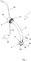
- an inner cannula 1 according to an embodiment of the present invention is shown in a perspective view.
- the inner cannula 1 has an arcuately curved tube 2 with a proximal end 3 and a distal end 4.
- a proximal opening 3 a is arranged at the proximal end 3 and a distal opening 4 a is arranged at the distal end 4.
- the tube 2 connecting the proximal opening 3a and the distal opening 4a is used to convey breathing gas.
- the proximal end 3 can be connected to a ventilation device for supplying breathing air, the proximal end 3 having a 15 mm connector 11 for this purpose.
- the distal end 4 is inserted into a patient's trachea through a tracheostoma.
- a cuff 5 is arranged on its outer circumference near the distal end 4 of the tube; more precisely, the cuff 5 is arranged in a ring section 6 which extends at least over the axial length of the cuff 5 and has a smaller outer diameter D TR than the outer diameter D TPC of the tube in the main section 7 located proximally in front of the cuff 5.
- the cuff 5 is a low-pressure cuff, the interior of which can be acted upon with a fluid, so that the cuff 5 can be completely unfolded and placed against the inner wall of a patient's trachea.
- the cuff 5 is connected to a control balloon with a filling valve 20 via a fluid line 19.
- the fluid is preferably air.
- the cuff 5 has a maximum axial extension of 5 mm to 30 mm.
- the cuff 5 has a distal section 5 b which, in a state in which the cuff 5 is completely filled, tapers in the direction of the distal end 4 of the tube 2.
- the radially tapering section 5b prevents or makes it more difficult for the distal tube opening to be blocked by a largely deflated cuff.
- the cuff 5 does not directly adjoin the free distal end 4 of the tube 2, but has an axial distance between the distal attachment point of the cuff 5 and the free distal end 4 of the tube 2.
- the axial distance is between 1 mm and 10 mm in size and is also intended to prevent the cuff 5 in its deflated state from being placed in front of the distal opening 4 of the tube 2 of the inner cannula 1 when the inner cannula 1 is withdrawn from the tube of an outer cannula.
- the proximal section 5a of the cuff 5 has a plate shape, with secretion from the subglottic on the section extending radially approximately perpendicular to the longitudinal axis in a state in which the inner cannula 1 is inserted into a trachea and the cuff 5 is completely filled Space the trachea can collect. Any secretion that may have accumulated can be sucked off through a suction opening 8.
- the suction opening 8 is arranged proximal to the cuff 5 within the ring section 6 and is connected to a suction line 8a.
- the suction line 8a is integrated into the wall of the tube 2 and merges at the proximal end 3 of the tube 2 into a tube extension 8b.
- the hose extension 8b can be connected to a suction device not shown here.
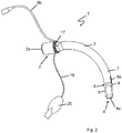
- Figure 2 is the inner cannula 1 according to the embodiment from FIG Figure 1 shown in a state in which the cuff 5 is deflated and placed on the outer circumference of the ring section 6.
- the cuff 5 indicated by a dashed line does not protrude beyond the radial outer circumference of the main section 7 of the tube 2 located proximally in front of the cuff 5, with the exception of thin and thus flexible folds of the cuff 5.
- the cuff 5 does not interfere with the insertion of the tube 2 of the inner cannula 1 into a tube of an outer cannula, because the thin folds of the cuff 5 nestle against the inner cannula wall of the ring section 6 or the already tight-fitting cuff material.
- the Figure 3 shows the previously related to the Figures 1 and 2 inner cannula 1 described in a state in which the inner cannula 1 is inserted into the tube 14 of an outer cannula 13.
- the embodiment referred to as a device for breathing air supply 12 consists of the previously described inner cannula 1 and an outer cannula 13.
- the outer cannula 13 has an arcuately curved tube 14 with a proximal end 15 and a distal end 16.
- the proximal end 15 has a proximal opening 15a and the distal end 16 has a distal opening 16a.
- the tube 2 of the inner cannula 1 is longer than the tube 14 of the outer cannula 13 and is dimensioned in such a way that after the introduction of the inner cannula 1 with its ring section 6 with the cuff 5 it protrudes beyond the distal end 16 of the outer cannula 13, the proximal end also The end of the inner cannula 1 still protrudes from the proximal end of the outer cannula 13.
- the suction opening 8 arranged in the ring section 6 is also exposed beyond the distal end 16 of the outer cannula 12.
- the outer diameter D TPC of the main section 7 of the tube 2 of the inner cannula 1 arranged proximally in front of the ring section 6 is slightly smaller than the inner diameter D AT of the tube 14 of the outer cannula 13.
- the outer surface of the section 7 accordingly rests against the inner surface of the tube 14 with little play, preferably 0.1 mm ⁇ diameter difference ⁇ 0.5 mm.
- the inner cannula 1 is detachably attached to the outer cannula 13.
- the inner cannula 1 has fastening means 17 at the proximal end 3 of the tube 2, as shown in FIG Figure 1 are shown.
- the outer cannula 13 also has a cannula shield 21 and a cuff 18.
- the cuff 18 is a fillable low-pressure cuff which is arranged on the outer circumference of the tube 14 of the outer cannula 13.
- the cuff 18 is connected by a fluid line 19 to a control balloon with a filling valve 20. In its filled state, the cuff 18 rests against the inner wall of the trachea of a patient and seals the outer cannula 13 from the trachea.
Description
Die vorliegende Erfindung betrifft eine Tracheostomiekanüle mit einem Tubus, welcher ein proximales Ende mit einer proximalen Öffnung und ein distales Ende mit einer distalen Öffnung und einen an seinem äußeren Umfang nahe des distalen Endes angeordneten Cuff aufweist.The present invention relates to a tracheostomy cannula with a tube which has a proximal end with a proximal opening and a distal end with a distal opening and a cuff arranged on its outer circumference near the distal end.
Die erfindungsgemäße Tracheostomiekanüle ist insbesondere für eine Verwendung als Innenkanüle vorgesehen, die in eine bereits vorhandene Tracheostomiekanüle (Außenkanüle) ein- und hindurchführbar ist, so dass das distale Ende der Innenkanüle aus dem distalen Ende der Außenkanüle hervorsteht. Die Innenkanüle kann aber, insbesondere für kurze Übergangszeiten, auch allein ohne die Außenkanüle verwendet werden.The tracheostomy cannula according to the invention is intended in particular for use as an inner cannula which can be inserted and passed through an existing tracheostomy cannula (outer cannula) so that the distal end of the inner cannula protrudes from the distal end of the outer cannula. However, the inner cannula can also be used on its own without the outer cannula, especially for short transition times.
Darüber hinaus betrifft die vorliegende Erfindung auch eine Vorrichtung zur Atemluftzuführung, insbesondere Endotrachealtubus oder Tracheostomiekanüle, jeweils bestehend aus einer Innenkanüle und einer Außenkanüle mit einem Tubus, wobei der Tubus der Außenkanüle ein proximales Ende mit einer proximalen Öffnung und ein distales Ende mit einer distalen Öffnung aufweist.In addition, the present invention also relates to a device for supplying breathing air, in particular an endotracheal tube or tracheostomy tube, each consisting of an inner cannula and an outer cannula with a tube, the tube of the outer cannula having a proximal end with a proximal opening and a distal end with a distal opening .
Tracheostomiekanülen werden für die Zuführung von Atemluft durch einen künstlichen Zugang, das sog. Tracheostoma, in die Trachea eines Patienten eingeführt. Das proximale Ende des bogenförmig gekrümmten Tubus ist außerhalb des Körpers eines Patienten mit einer Beatmungsvorrichtung zur Atemluftzufuhr verbindbar, während das distale Ende der Tracheostomiekanüle innerhalb der Trachea des Patienten mündet. Der die zwei Enden miteinander verbindende Tubus dient der Hindurchleitung von Atemgas, sodass Atemgas über die Trachea in die Lunge des Patienten eingeleitet bzw. aus der Trachea zurückgeführt werden kann.Tracheostomy cannulas are inserted into the trachea of a patient through an artificial access, the so-called tracheostoma, for the supply of breathing air. The proximal end of the arcuately curved tube can be connected outside of the patient's body to a ventilation device for supplying breathing air, while the distal end of the tracheostomy cannula opens inside the patient's trachea. The tube connecting the two ends is used to pass breathing gas through so that breathing gas can be introduced into the patient's lungs via the trachea or returned from the trachea.
Für eine zuverlässige Versorgung mit Sauerstoff bzw. Atemgas ist es wichtig, dass der Tubus einer Tracheostomiekanüle, dessen Außendurchmesser zur Vermeidung von Verletzungen deutlich kleiner als der Innendurchmesser der Trachea ist, gegenüber der Innenwand der Trachea abgedichtet und möglichst kein oder wenig Atemgas an dem Tubus vorbei und über die oberen Atemwege zurückströmen kann bevor es in die Lunge gelangt. Hierfür ist an dem äußeren Umfang des Tubus nahe seines distalen Endes ein sogenannter Cuff (aufblasbare Manschette) angeordnet. Nach dem Einführen einer Tracheostomiekanüle in die Trachea eines Patienten wird der zunächst leere Cuff mit Gas (z. B. Luft) gefüllt und aufgebläht. Durch das Aufblähen legt sich der Cuff an die Innenwand der Trachea an und dichtet den Tubus gegenüber der Innenwand der Trachea ab. Der Cuff verhindert auch, dass Sekret aus dem subglottischen Raum an dem Tubus vorbei in die Bronchien gelangt. Solches Sekret enthält zumeist Bakterien, die bei einer Aspiration zu Pneumonien führen können, die eine häufige Komplikation bei langzeitbeatmeten Patienten darstellen.For a reliable supply of oxygen or respiratory gas, it is important that the tube of a tracheostomy tube, the outer diameter of which is significantly smaller than the inner diameter of the trachea to avoid injuries, is sealed against the inner wall of the trachea and that as little or no respiratory gas as possible passes the tube and can flow back through the upper respiratory tract before it reaches the lungs. For this purpose, a so-called cuff (inflatable cuff) is arranged on the outer circumference of the tube near its distal end. After a tracheostomy tube has been inserted into a patient's trachea, the initially empty cuff becomes filled with gas (e.g. air) and inflated. When inflated, the cuff rests against the inner wall of the trachea and seals the tube against the inner wall of the trachea. The cuff also prevents secretion from the subglottic space from passing the tube into the bronchi. Such secretions mostly contain bacteria which can lead to pneumonia during aspiration, which are a frequent complication in long-term ventilated patients.
Da die Tracheostomiekanüle in der Regel für eine Langzeitbeatmung vorgesehen ist, soll sie den Patienten möglichst wenig beeinträchtigen, die Schleimhaut der Trachea nicht beschädigen und eine sichere Beatmung des Patienten ermöglichen.Since the tracheostomy cannula is usually intended for long-term ventilation, it should impair the patient as little as possible, should not damage the mucous membrane of the trachea and enable safe ventilation of the patient.
Aus der
Auch die
Stellt sich nach dem Einsetzen heraus, dass die Tracheostomiekanüle für den zu behandelnden Patienten zu groß, zu klein, zu kurz und/oder zu lang ist, kann sie Schmerzen verursachen oder es kann sogar ihre Funktion beeinträchtigt sein. Die Tracheostomiekanüle muss dann durch eine besser passende Tracheostomiekanüle ersetzt werden. Darüber hinaus können Situationen auftreten, in denen die Tracheostomiekanüle beschädigt oder verunreinigt ist oder aus anderen Gründen ausgewechselt werden muss. Bei der Entfernung einer herkömmlichen Tracheostomiekanüle aus der Trachea ist es praktisch unvermeidbar, dass Sekret, welches sich zwischenzeitlich angesammelt hat, an dem Tubus vorbei in die Bronchien und in die Lunge gelangt.If, after insertion, it turns out that the tracheostomy tube is too big, too small, too short and / or too long for the patient to be treated, it can cause pain or even its function can be impaired. The tracheostomy tube must then be replaced with a better fitting tracheostomy tube. In addition, situations may arise in which the tracheostomy tube is damaged, contaminated, or needs to be replaced for other reasons. When removing a conventional tracheostomy cannula from the trachea, it is practically inevitable that secretion that has accumulated in the meantime will pass the tube into the bronchi and into the lungs.
Demgegenüber besteht eine Aufgabe der vorliegenden Erfindung darin, eine Tracheostomiekanüle bereitzustellen, die einen sicheren Kanülenwechsel ermöglicht und dabei die Gefahr einer Aspiration von Sekret deutlich verringert.In contrast, an object of the present invention is to provide a tracheostomy cannula which enables the cannula to be changed safely and at the same time significantly reduces the risk of secretion being aspirated.
Erfindungsgemäß wird diese Aufgabe durch eine Tracheostomiekanüle mit den Merkmalen des Anpruchs 1 gelöst. Bei dieser Tracheostomiekanüle weist der Tubus nahe seines distalen Endes einen sich zumindest über die axiale Länge des Cuffs erstreckenden verjüngten Abschnitt mit reduziertem Außendurchmesser auf, der einen kleineren Außendurchmesser hat als der Tubus in dem proximal davorliegenden Hauptabschnitt, wobei vorzugsweise die Länge des verjüngten Abschnittes mindestens der Länge des Cuffs entspricht und weniger als ein Drittel der Länge des Tubus beträgt und wobei weiterhin bevorzugt das proximale Ende des Cuffs um mindestens zwei Drittel der Tubuslänge von dem proximalen Ende des Tubus beabstandet ist Weiterhin wiest der Ringabschnitt mit dem kleineren Außendurchmesser DTR eine Absaugöffnung auf, die proximal von dem Cuff an dem äußeren Umfang des Tubus (der Innenkanüle) angeordnet ist. Die proximal von dem Cuff angeordnete Absaugöffnung dient dem Absaugen von sich möglicherweise proximal vor dem Cuff ansammelnden Sekret. Dies ist insbesondere beim Wechsel von Kanülen von Bedeutung weil dann der Cuff bewegt und gegebenenfalls entleert wird und die Abdichtung nicht durchgehend sicher gewährleisten kann.According to the invention, this object is achieved by a tracheostomy cannula with the features of
Die erfindungsgemäße Tracheostomiekanüle ist dafür vorgesehen, in eine zweite Tracheostomiekanüle eingebracht zu werden. Im Sinne der vorliegenden Erfindung wird die zweite Tracheostomiekanüle auch als Außenkanüle und die erste, innenliegende Tracheostomiekanüle als Innenkanüle bezeichnet. Die Tracheostomiekanüle ist jedoch auch ohne weiteres, insbesondere kurzzeitig, allein verwendbar, wobei die Vorteile der erfindungsgemäßen Tracheostomiekanüle vor allem in Verbindung mit einer Außenkanüle realisiert werden.The tracheostomy cannula according to the invention is intended to be inserted into a second tracheostomy cannula. In the context of the present invention, the second tracheostomy cannula is also referred to as the outer cannula and the first, inner tracheostomy cannula is referred to as the inner cannula. The tracheostomy cannula can, however, also be used without further ado, in particular for a short time, on its own, the advantages of the tracheostomy cannula according to the invention being realized primarily in connection with an outer cannula.
Der Abschnitt mir reduziertem Durchmesser kann z. B. stufenförmig von dem proximal davor liegenden Abschnitt des Tubus abgesetzt sein oder auch als eine mindestens teilweise konische Verjüngung der Außenseite des Tubus im distalen Bereich ausgestaltet sein. Sinn der Verjüngung ist die Aufnahme des eng anliegenden Cuffs im ungefüllten Zustand in der Weise, dass die Kanüle als Innenkanüle zusammen mit dem im verjüngten Abschnitt außen anliegenden Cuff durch eine Außenkanüle hindurchgeführt werden kann, ohne den Cuff zu beschädigen, wobei der Außendurchmesser im proximalen Bereich des Tubus dem Innendurchmesser der Außenkanüle entsprechen kann. Die Innenkanüle einschließlich des entleerten und außen im verjüngten Bereich anliegenden Cuff hat also in dem verjüngten Abschnitt einen Durchmesser, der nicht über den Durchmesser des Hauptabschnitts im proximalen Bereich hinausgeht.The section with reduced diameter can, for. B. be stepped off from the proximally in front of the section of the tube or designed as an at least partially conical tapering of the outside of the tube in the distal area. The purpose of the tapering is to accommodate the tightly fitting cuff in the unfilled state in such a way that the cannula, as an inner cannula, can be passed through an outer cannula together with the cuff fitted on the outside in the tapered section without damaging the cuff, the outer diameter being in the proximal area of the tube can correspond to the inner diameter of the outer cannula. The inner cannula, including the deflated cuff and lying outside in the tapered area, therefore has a diameter in the tapered section which does not exceed the diameter of the main section in the proximal area.
Die Innenkanüle weist z. B. einen Tubus auf, der ebenso wie bei der Außenkanüle bogenförmig gekrümmt ist. Die Innenkanüle kann aber auch als gerade Kanüle ausgebildet sein, die erst beim Einführen durch die Außenkanüle deren gebogene Form annimmt. Der Tubus hat ein proximales Ende mit einer proximalen Öffnung sowie ein distales Ende mit einer distalen Öffnung. Dabei bezeichnet das "distale Ende" der jeweiligen Kanüle im Sinne der vorliegenden Erfindung das in die Trachea eingeführte bzw. in die Trachea einführbare Ende, das von einem behandelnden Arzt oder medizinischem Personal weiter entfernt liegt als das proximale Ende. Die Begriffe "distal" (fern gelegen) und "proximal" (nahe gelegen) werden also aus der Sicht einer behandelnden Person definiert. Entsprechend ist das "proximale Ende" für die Anordnung außerhalb des Körpers eines Patienten vorgesehen.The inner cannula has z. B. on a tube, which is curved like an arc like the outer cannula. The inner cannula can, however, also be designed as a straight cannula which only assumes its curved shape when it is inserted through the outer cannula. The tube has a proximal end with a proximal opening and a distal end with a distal opening. The “distal end” of the respective cannula in the sense of the present invention denotes the end introduced into the trachea or insertable into the trachea, which is further away than the proximal end from the attending physician or medical personnel. The terms “distal” (remote) and “proximal” (near) are thus defined from the perspective of the person treating. Correspondingly, the “proximal end” is intended for placement outside the body of a patient.
In einem Zustand, in dem die Innenkanüle in eine Außenkanüle eingebracht ist, ist der an dem äußeren Umfang nahe des distalen Endes des Tubus der Innenkanüle angeordnete Cuff jenseits des distalen Endes des Tubus der Außenkanüle angeordnet, um gegenüber der Innenwand der Trachea abdichten zu können. Im Sinne der vorliegenden Erfindung ist der Cuff "nahe des distalen Endes des Tubus" angeordnet, wenn der Cuff innerhalb eines axialen Endabschnittes des Tubus angeordnet ist, der, gemessen von dem distalen Ende des Tubus, sich über einen axialen Abschnitt des Cuffs erstreckt, dessen Länge maximal das Dreifache und minimal das Einfache des Innendurchmessers des Tubus beträgt.In a state in which the inner cannula is inserted into an outer cannula, the cuff arranged on the outer circumference near the distal end of the tube of the inner cannula is arranged on the other side of the distal end of the tube of the outer cannula in order to be able to seal against the inner wall of the trachea. In the sense of the present invention, the cuff is arranged "near the distal end of the tube" if the cuff is arranged within an axial end section of the tube which, measured from the distal end of the tube, extends over an axial section of the cuff Length is a maximum of three times and a minimum of simple of the inner diameter of the tube.
In einer Ausführungsform beträgt der Abstand zwischen dem freien distalen Ende des Tubus und dem distalen Ansatzpunkt des Cuffs zwischen 1 mm und 10 mm, vorzugsweise zwischen 3 mm und 6 mm. Der Abstand zwischen dem distalen Ansatzpunkt des Cuffs und dem freien distalen Ende des Tubus soll verhindern, dass sich der Cuff bei einem Zurückziehen der Innenkanüle aus dem Tubus einer Außenkanüle vor die distale Öffnung des Tubus der Innenkanüle legt. Der proximale Ansatzpunkt des Cuffs kann beispielsweise in einem Abstand von 15 mm bis 40 mm von dem distalen Ende des Tubus liegen. Der Durchmesser des Cuffs, welcher senkrecht zur Tubus-Achse gemessen wird, beträgt minimal das Doppelte des Tubus-Innendurchmessers und maximal das Vierfache. Um zu verhindern, dass sich der Cuff der Innenkanüle versehentlich vor die distale Öffnung des Tubus der Innenkanüle legt wird eine Cuff-Form bevorzugt, bei der sich der Cuff in Richtung des distalen Endes konisch verjüngt.In one embodiment, the distance between the free distal end of the tube and the distal attachment point of the cuff is between 1 mm and 10 mm, preferably between 3 mm and 6 mm. The distance between the distal attachment point of the cuff and the free distal end of the tube is intended to prevent the cuff from being positioned in front of the distal opening of the tube of the inner cannula when the inner cannula is withdrawn from the tube of an outer cannula. The proximal attachment point of the cuff can, for example, be at a distance of 15 mm to 40 mm from the distal end of the tube. The diameter of the cuff, which is measured perpendicular to the tube axis, is at least twice the inner diameter of the tube and at most four times. In order to prevent the cuff of the inner cannula from accidentally lying in front of the distal opening of the tube of the inner cannula, a cuff shape is preferred in which the cuff tapers conically in the direction of the distal end.
Damit die Innenkanüle in die Außenkanüle einbringbar ist, muss notwendigerweise der Innendurchmesser des Tubus der Außenkanüle etwas größer als der Außendurchmesser des Tubus der Innenkanüle sein. Gemäß einer Ausführungsform sind der Innendurchmesser des Tubus der Außenkanüle und der Außendurchmesser des Tubus der Innenkanüle derart aufeinander abgestimmt, dass die Innenkanüle mit geringem Widerstand in der Außenkanüle gleiten kann.So that the inner cannula can be introduced into the outer cannula, the inner diameter of the tube of the outer cannula must necessarily be somewhat larger than the outer diameter of the tube of the inner cannula. According to one embodiment, the inner diameter of the tube of the outer cannula and the outer diameter of the tube of the inner cannula are matched to one another in such a way that the inner cannula can slide in the outer cannula with little resistance.
Damit der Tubus der Innenkanüle samt dem an seinem äußeren Umfang angeordneten Cuff in den Tubus einer Außenkanüle einführbar ist, ist erfindungsgemäß vorgesehen, dass der Tubus an seinem distalen Ende einen sich zumindest über die axiale Länge des Cuffs erstreckenden Abschnitt aufweist dessen Außendurchmesser DTR kleiner als der Außendurchmesser des Tubus DTPC in dem proximal vor dem Ringabschnitt liegenden Abschnitt ist, der nachstehend als Hauptabschnittbezeichnet wird, so dass der leere an dem verjüngten Abschnitt anliegende Cuff den Gesamtdurchmesser nicht oder nicht wesentlich über den Außendurchmesser des Tubus außerhalb des verjüngten Abschnitts vergrößert. Der verjüngte Abschnitt wird nachstehend auch als Ringabschnitt bezeichnet, da er zumindest in bevorzugten Varianten eine Rotationsymmetrie aufweist.So that the tube of the inner cannula together with the cuff arranged on its outer circumference can be inserted into the tube of an outer cannula, the invention provides that the tube at its distal end has a section which extends at least over the axial length of the cuff and whose outer diameter D TR is smaller than the outer diameter of the tube D is TPC in the section located proximally in front of the ring section, which is hereinafter referred to as the main section, so that the empty cuff resting on the tapered section does not increase the overall diameter or does not increase the overall diameter significantly beyond the outer diameter of the tube outside the tapered section. The tapered section is also referred to below as a ring section, since it has a rotational symmetry, at least in preferred variants.
Demnach steht der äußere Umfang des Cuffs in einem leeren und an den äußeren Umfang des Tubus angelegten Zustand nicht über den äußeren Umfang des Tubus in dem proximal vor dem Cuff liegenden Hauptabschnitt über. In seinem leeren und an den äußeren Umfang des Tubus angelegten Zustand, kann der Cuff vollständig in einem durch den kleineren Außendurchmesser DTR gebildeten Ringraum aufgenommen werden. Beim Einführen des Tubus der Innenkanüle in den Tubus einer Außenkanüle ist der Cuff auf dieser Weise in dem Ringraum angeordnet und vor Beschädigungen beim Ein- bzw. Hindurchführen geschützt. Die verwendeten Cuffs haben bevorzugt eine geringe Wandstärke zwischen 5 µm und 45 µm. Im leeren und an den äußeren Umfang des Tubus angelegten Zustand weist der Cuff im Allgemeinen noch Falten auf, die radial nach außen abstehen können, Diese muss man gegebenenfalls mit geringer Kraft (z. B. 0,03 N) an den Tubus andrücken. Wenn diese Falten an den Tubus bzw. an den entleerten Cuff angelegt sind, passt der Tubus mit dem Cuff problemlos in die entsprechende Außenkanüle. Insbesondere wenn der Cuff beispielsweise eine Niederdruckmanschette ("High Volume Low Pressure Cuff") ist, können nach dem Entleeren des Cuffs zunächst schmale Falten des Cuffmaterials über den äußeren Umfang des Tubus in dem proximal vor dem Cuff liegenden Hauptabschnitt überstehen. Beim Einführen der Innenkanüle in eine Außenkanüle, werden diese Falten problemlos an den Tubus bzw. den entleerten Cuff angedrückt, sodass das Einführen nicht erschwert und der Cuff auch nicht beschädigt wird.Accordingly, the outer circumference of the cuff does not protrude beyond the outer circumference of the tube in the main section located proximally in front of the cuff in an empty state in which it is placed on the outer circumference of the tube. In its empty state and placed on the outer circumference of the tube, the cuff can be completely received in an annular space formed by the smaller outer diameter D TR . When the tube of the inner cannula is inserted into the tube of an outer cannula, the cuff is arranged in this way in the annular space and is protected from damage when it is inserted or passed through. The cuffs used preferably have a small wall thickness between 5 μm and 45 μm. When empty and placed on the outer circumference of the tube, the cuff generally still has folds that can protrude radially outward. These may have to be pressed onto the tube with little force (e.g. 0.03 N). When these folds are placed on the tube or the deflated cuff, the tube with the cuff fits easily into the corresponding outer cannula. In particular if the cuff is, for example, a high-volume, low-pressure cuff, after the cuff has been deflated, narrow folds of the cuff material can initially protrude over the outer circumference of the tube in the main section proximally in front of the cuff. When inserting the inner cannula into an outer cannula, these folds are easily attached to the tube or the deflated cuff is pressed down so that insertion is not difficult and the cuff is not damaged.
Der kleinere Außendurchmesser DTR des verjüngten Abschnittes ist über die axiale Länge des verjüngten Abschnittes nicht notwendigerweise konstant, insbesondere wenn der verjüngte Abschnitt z. B. durch eine konische Verjüngung gebildet wird. Auch eine Kreisform oder Ringform des durch die Verjüngung gebildeten Freiraums ist nicht zwingend notwendig. Wesentlich ist lediglich, das durch die Verjüngung ein Freiraum zwischen der Außenseite des Tubus im verjüngten Bereich und einer gedachten Fortsetzung seines Hauptabschnittes vorliegt, die gleichzeitig auch eine radial innere Grenze für den Verlauf der Innenseite einer Außenkanüle definiert. Dieser Freiraum ermöglicht und erleichtert somit das Einbringen der Innenkanüle mit dem Cuff in und durch die Außenkanüle, ohne dass dabei der in dem Ringabschnitt angeordnete Cuff durch starke Reibung beschädigt wird. Der Tubus besteht im Wesentlichen aus einem Hauptabschnitt mit einem proximalen und einem distalen Ende, wobei der Ringabschnitt mit reduzierten Außendurchmesser nahe des distalen Endes liegt und das proximale Ende gegebenenfalls einen zusätzlich vergrößerten Außendurchmesser haben kann. Der Hauptabschnitt macht den größten Teil der Länge des Tubus aus und erstrecht sich proximal von dem Ringabschnitt. Mit "Durchmesser des Tubus" ist im Allgemeinen der Außendurchmesser des Hauptabschnitts gemeint. Der Innendurchmesser des Tubus ist vorzugsweise über seine gesamte Länge hinweg konstant. Es versteht sich, dass man den Grundgedanken eines verjüngten Abschnittes gegenüber dem Hauptabschnitt auch auf einen konischen Tubus, d. h. eine Tubus mit leicht konischem Hauptabschnitt anwenden kann, indem die Verjüngung eine zusätzliche Verjüngung gegenüber der gedachten Fortsetzung des konischen Hauptabschnittes darstellt.The smaller outer diameter D TR of the tapered section is not necessarily constant over the axial length of the tapered section, in particular if the tapered section z. B. is formed by a conical taper. A circular shape or ring shape of the free space formed by the taper is also not absolutely necessary. It is only essential that the tapering creates a free space between the outside of the tube in the tapered area and an imaginary continuation of its main section, which at the same time also defines a radially inner limit for the course of the inside of an outer cannula. This free space enables and thus facilitates the introduction of the inner cannula with the cuff into and through the outer cannula without the cuff arranged in the ring section being damaged by strong friction. The tube essentially consists of a main section with a proximal and a distal end, the ring section with a reduced outer diameter being close to the distal end and the proximal end optionally being able to have an additionally enlarged outer diameter. The main section makes up most of the length of the tube and extends proximally from the ring section. The "diameter of the tube" generally means the outside diameter of the main section. The inner diameter of the tube is preferably constant over its entire length. It goes without saying that the basic idea of a tapered section compared to the main section can also be applied to a conical tube, ie a tube with a slightly conical main section, in that the taper represents an additional taper compared to the imaginary continuation of the conical main section.
Muss eine in die Trachea eines zu behandelnden Patienten eingeführte Tracheostomiekanüle herausgenommen oder ausgewechselt werden, kann zunächst die erfindungsgemäße Innenkanüle in die vorhandene Tracheostomiekanüle eingebracht werden, die dann als Außenkanüle dient. Die in der Trachea angeordnete Außenkanüle dient dabei als Führung für die Innenkanüle. Währenddessen oder anschließend kann die Innenkanüle die Funktion der Außenkanüle übernehmen, indem ihre proximale Öffnung beispielsweise über einen aufsteckbaren 15 mm Konnektor mit einer Beatmungseinrichtung verbunden wird. Der Cuff der Innenkanüle wird nach dem Hindurchführen durch die Außenkanüle aufgebläht und dichtet dann die Innenkanüle in der Trachea nach außen ab. Dann wird der Cuff der Außenkanüle entleert und die Außenkanüle kann von der Innenkanüle abgezogen und aus der Trachea und dem Tracheostoma entfernt werden.If a tracheostomy cannula inserted into the trachea of a patient to be treated has to be removed or replaced, the inner cannula according to the invention can first be inserted into the existing tracheostomy cannula, which then serves as the outer cannula. The outer cannula arranged in the trachea serves as a guide for the inner cannula. During this or afterwards, the inner cannula can take over the function of the outer cannula by connecting its proximal opening to a ventilation device, for example via a plug-on 15 mm connector. The cuff of the inner cannula is inflated after being passed through the outer cannula and then seals the inner cannula from the outside in the trachea. Then the cuff of the outer cannula is deflated and the outer cannula can be withdrawn from the inner cannula and removed from the trachea and the tracheostoma.
Der Cuff der Innenkanüle verhindert, dass sich bei und nach dem Entfernen der Außenkanüle Sekret, welches sich an oder oberhalb des Cuffs der Außenkanüle in dem subglottischen Raum angesammelt hat, in die Bronchien gelangt.The cuff of the inner cannula prevents secretion that has accumulated on or above the cuff of the outer cannula in the subglottic space from getting into the bronchi during and after the removal of the outer cannula.
Da die erfindungsgemäße Innenkanüle mindestens zeitweise allein für die Zufuhr der Atemluft zu einem Patienten verwendet wird, ist es zweckmäßig wenn sie an ihrem proximalen Ende mit einem 15 mm Standardanschluss versehen ist, der auch lösbar mit dem proximalen Ende des Hauptabschnitts verbunden sein kann.Since the inner cannula according to the invention is at least temporarily used solely for the supply of breathing air to a patient, it is useful if it is provided with a 15 mm standard connector at its proximal end, which can also be detachably connected to the proximal end of the main section.
Die Innenkanüle kann darüber hinaus (ohne den 15 mm Konnektor) auch als Führung für eine neu über die Innenkanüle in die Trachea einzuführende Außenkanüle verwendet werden.The inner cannula can also be used (without the 15 mm connector) as a guide for a new outer cannula to be inserted into the trachea via the inner cannula.
Sekret, welches beim Wechsel der Außenkanüle oder zwischen der Außenkanüle und der Innenkanüle hinabfließt, wird durch den Cuff der Innenkanüle aufgehalten und kann durch die proximal von dem Cuff angeordnete Absaugöffnung abgesaugt werden. Nach dem Aufschieben einer neuen Außenkanüle auf die Innenkanüle, kann der Cuff der Außenkanüle aufgebläht werden und dichtet nunmehr die Außenkanüle in der Trachea ab. Anschließend kann gegebenenfalls nochmals eine Absaugung von Sekret aus dem Raum oberhalb des Cuffs der Innenkanüle (d. h. zwischen dem Cuff der Innenkanüle und dem Cuff der Außenkanüle) erfolgen, und die Innenkanüle kann dann nach dem Entleeren ihres Cuffs wieder aus der Außenkanüle zurückgezogen werden. Auf diese Weise kann ein sicherer Wechsel einer Tracheoestomiekanüle erfolgen, ohne dass die Gefahr besteht, dass Sekret während des Wechsels in die Bronchien oder die Lunge eines Patienten gerät, weil ununterbrochen eine Abdichtung entweder durch den Cuff der Außenkanüle oder durch den Cuff der Innenkanüle gewährleistet ist. Die vorhandene bzw. für die längere Behandlungsdauer vorgesehene Tracheostomiekanüle hat dabei die Funktion der Außenkanüle und die erfindungsgemäße Tracheostomiekanüle übernimmt die Funktion der Innenkanüle.Secretion that flows down when the outer cannula is changed or between the outer cannula and the inner cannula is stopped by the cuff of the inner cannula and can be sucked off through the suction opening located proximally of the cuff. After a new outer cannula has been pushed onto the inner cannula, the cuff of the outer cannula can be inflated and now seals the outer cannula in the trachea. Subsequently, if necessary, secretion can again be aspirated from the space above the cuff of the inner cannula (i.e. between the cuff of the inner cannula and the cuff of the outer cannula), and the inner cannula can then be withdrawn from the outer cannula after its cuff has been emptied. In this way, a tracheoestomy cannula can be changed safely without the risk of secretion getting into the bronchi or lungs of a patient during the change, because a continuous seal is ensured either by the cuff of the outer cannula or the cuff of the inner cannula . The existing tracheostomy cannula or intended for the longer treatment duration has the function of the outer cannula and the tracheostomy cannula according to the invention assumes the function of the inner cannula.
In einer Ausführungsform weist der Ringabschnitt im Bereich der Absaugöffnung einen stufenförmigen Übergang zwischen dem Außendurchmesser DTR und DTPC auf. Die Stufe zwischen den Außendurchmessern DTR und DTPC trennt den Ringabschnitt in dem der Cuff angeordnet ist und den Hauptabschnitt. Die Absaugöffnung ist in einer Ausführungsform im Bereich dieser Stufe und proximal vor dem Cuffansatz angeordnet. Die Stufe kann auch die Form eines konischen Übergangs haben.In one embodiment, the ring section has a stepped transition between the outer diameter D TR and D TPC in the area of the suction opening. The step between the outer diameters D TR and D TPC separates the ring section in which the cuff is arranged and the main section. In one embodiment, the suction opening is arranged in the area of this step and proximally in front of the cuff attachment. The step can also have the shape of a conical transition.
Zum Absaugen von Sekret ist die Absaugöffnung mit einer Absaugleitung verbunden, wobei die Absaugleitung in einer Ausführungsform mit dem Tubus verklebt oder in die Wand des Tubus integriert ist. Eine mit dem Tubus verklebte oder in die Wand des Tubus integrierte Absaugleitung ist vor Beschädigungen beim Ein- oder Ausführen der Innenkanüle in eine Außenkanüle geschützt. Eine verklebte oder in das Material eingelassene Absaugleitung birgt auch nicht die Gefahr, dass die Absaugleitung beim Ein- oder Ausführen der Innenkanüle in einer Außenkanüle eingeklemmt wird. An ihrem proximalen Ende ist die Absaugleitung mit einer Saug- und/oder Spülvorrichtung verbindbar. Das proximale Ende der Absaugleitung kann an dem proximalen Ende des Tubus der Innenkanüle enden oder als Schlauchfortsatz ausgeführt sein.For sucking off secretions, the suction opening is connected to a suction line, the suction line being glued to the tube in one embodiment or being integrated into the wall of the tube. A suction line glued to the tube or integrated in the wall of the tube is protected from damage when the inner cannula is inserted or removed from an outer cannula. A suction line that is glued or embedded in the material also does not involve the risk that the suction line will be jammed in an outer cannula when the inner cannula is inserted or removed. At its proximal end, the suction line can be connected to a suction and / or rinsing device. The proximal end of the suction line can end at the proximal end of the tube of the inner cannula or be designed as a tube extension.
In einer Ausführungsform weist der Cuff der Innenkanüle in seinem gefüllten Zustand eine maximale axiale Ausdehnung von 5 mm bis 30 mm, vorzugsweise 10 mm bis 20 mm, auf.In one embodiment, the cuff of the inner cannula in its filled state has a maximum axial extent of 5 mm to 30 mm, preferably 10 mm to 20 mm.
In einer Ausführungsform ist der Cuff der Innenkanüle eine entfaltbare Niederdruckmanschette, die mit einem Fluid befüllbar ist.In one embodiment, the cuff of the inner cannula is a deployable low-pressure cuff that can be filled with a fluid.
In einer weiteren Ausführungsform weist der Cuff einen proximalen Abschnitt auf, dessen Außendurchmesser sich in einem gefüllten Zustand des Cuffs nach proximal verjüngt, und/oder einen distalen Abschnitt, dessen Außendurchmesser sich in einem gefüllten Zustand des Cuffs nach distal verjüngt, auf. Die sich verjüngenden Abschnitte tragen dazu bei, dass sich der Cuff in seinem entleerten Zustand nicht über seinen proximalen und/oder distalen Ansatzpunkt hinaus erstreckt. Insbesondere verhindert der sich nach distal verjüngende Abschnitt, dass sich der leere Cuff vor die distale Öffnung des Tubus der Innenkanüle legen kann. Der sich nach proximal verjüngende Abschnitt und/oder der sich nach distal verjüngende Abschnitt verhindert außerdem, dass Teile des Cuffs beim Ein- und/oder Ausführen der Innenkanüle in eine bzw. aus einer Außenkanüle zwischen den Kanülen eingeklemmt werden.In a further embodiment, the cuff has a proximal section, the outside diameter of which tapers proximally when the cuff is filled, and / or a distal section, the outside diameter of which tapers distally when the cuff is filled. The tapering sections help ensure that the cuff does not extend beyond its proximal and / or distal attachment point in its deflated state. In particular, the section which tapers in the distal direction prevents the empty cuff from being able to lie in front of the distal opening of the tube of the inner cannula. The section tapering in the proximal direction and / or the section tapering in the distal direction also prevents parts of the cuff from becoming trapped between the cannulas when the inner cannula is inserted and / or removed from an outer cannula.
Um möglicherweise an der Innenseite der Trachea oder an der Außenseite der Innenkanüle oder der Außenseite einer Außenkanüle herabfließendes Sekret zu sammeln, weist der Cuff in einer Ausführungsform einen proximal angeordneten Abschnitt mit einer Tellerform auf. Der tellerförmige, sich vorzugsweise relativ zu der Längsachse der Innenkanüle rotationssymmetrische erstreckende Abschnitt, erstreckt sich quer zu der Längsachse der Innenkanüle und bildet so einen Abschnitt zum Auffangen von anfallendem Sekret.In order to collect secretion flowing down possibly on the inside of the trachea or on the outside of the inner cannula or on the outside of an outer cannula, in one embodiment the cuff has a proximally arranged section with a plate shape. The plate-shaped section, which is preferably rotationally symmetrical relative to the longitudinal axis of the inner cannula, extends transversely to the longitudinal axis of the inner cannula and thus forms a section for collecting secretion that occurs.
In einer Ausführungsform hat der Tubus an seinem proximalen Ende einen Außendurchmesser DTP, der größer als der Außendurchmesser des Tubus DTPC des Hauptabschnittes ist, wobei der Außendurchmesser DTP um mindestens 3 % vorzugsweise um maximal 20 %, z. B. um etwa 10 %, größer ist als der Außendurchmesser DTPC. Der proximale Abschnitt mit dem größeren Außendurchmesser DTP verhindert, dass sich die Innenkanüle ungewollt weiter in den Tubus einer Außenkanüle hineinbewegt, wobei vorausgesetzt ist, dass der Innendurchmesser der Außenkanüle um weniger als 5 % vom Außendurchmesser des Hauptabschnittes abweicht. Der Abschnitt mit dem größeren Außendurchmesser DTP kann auch als Mittel zum Befestigen der Innenkanüle in einer Außenkanüle verwendet werden, insbesondere in Verbindung mit einem konischen Übergang zum Hauptabschnitt. Der Abschnitt mit dem größeren Außendurchmesser DTP kann dabei nach Art einer Presspassung in den Tubus einer Außenkanüle gedrückt und so befestigt werden.In one embodiment, the tube at its proximal end has an outer diameter D TP which is greater than the outer diameter of the tube D TPC of the main section, the outer diameter D TP by at least 3%, preferably by a maximum of 20%, e.g. B. by about 10%, is larger than the outer diameter D TPC . The proximal section with the larger outer diameter D TP prevents the inner cannula from inadvertently moving further into the tube of an outer cannula, provided that the inner diameter of the outer cannula deviates by less than 5% from the outer diameter of the main section. The section with the larger outer diameter D TP can also be used as a means for fastening the inner cannula in an outer cannula can be used, in particular in connection with a conical transition to the main section. The section with the larger outer diameter D TP can be pressed into the tube of an outer cannula in the manner of a press fit and thus fastened.
In einer weiteren Ausführungsform weist das proximale Ende des Tubus kein Kanülenschild auf. Ein Kanülenschild dient im Allgemeinen der Befestigung einer Tracheostomiekanüle bei einer Dauerbehandlung und verhindert, dass die in die Trachea eingeführte Kanüle verrutscht. Weil aber die Innenkanüle im Allgemeinen nur für eine kurzzeitige Verwendung vorgesehen oder aber an einer Außenkanüle befestigbar ist bzw. durch ein Anschlussstück an einem vollständigen Hineinrutschen in die Außenkanüle gehindert ist, es ist es nicht erforderlich, dass die Innenkanüle ein Kanülenschild aufweist. Die Innenkanüle kann an der Außenkanüle befestigt werden.In a further embodiment, the proximal end of the tube does not have a cannula shield. A cannula shield is generally used to attach a tracheostomy cannula during long-term treatment and prevents the cannula inserted into the trachea from slipping. However, because the inner cannula is generally only intended for short-term use or can be attached to an outer cannula or is prevented from slipping completely into the outer cannula by a connector, it is not necessary for the inner cannula to have a cannula shield. The inner cannula can be attached to the outer cannula.
Zum Anschluss an eine Vorrichtung zur Atemluftzuführung weist das proximale Ende des Tubus in einer Ausführungsform einen 15 mm Konnektor auf.In one embodiment, the proximal end of the tube has a 15 mm connector for connection to a device for supplying breathing air.
In einer Ausführungsform weist der Tubus ein Phonationsfenster auf, welches proximal zu dem Cuff an dem distalen Ende des Tubus angeordnet ist. Zweckmäßigerweise besteht das Phonationsfenster aus einer oder mehreren Durchbrechungen in der Wand des Tubus. Vorzugsweise ist das Phonationsfenster proximal zu einer Absaugöffnung angeordnet. Wird in einer Vorrichtung zur Atemluftzuführung eine Innenkanüle und eine Außenkanüle verwendet, so ist das Phonationsfenster der Innenkanüle zweckmäßigerweise in einem Bereich des Tubus der Innenkanüle angeordnet, der aus der distalen Öffnung der Außenkanüle hervorsteht. Alternativ kann die Außenkanüle ebenfalls ein Phonationsfenster proximal zum Cuff der Innenkanüle aufweisen, welches zweckmäßigerweise in eine mit dem Phonationsfenster der Innenkanüle mindestens teilweise überlappende Position gebracht werden kann.In one embodiment, the tube has a phonation window which is arranged proximal to the cuff at the distal end of the tube. The phonation window expediently consists of one or more openings in the wall of the tube. The phonation window is preferably arranged proximal to a suction opening. If an inner cannula and an outer cannula are used in a device for supplying breathing air, the phonation window of the inner cannula is expediently arranged in a region of the tube of the inner cannula which protrudes from the distal opening of the outer cannula. Alternatively, the outer cannula can also have a phonation window proximal to the cuff of the inner cannula, which can expediently be brought into a position at least partially overlapping with the phonation window of the inner cannula.
In einer Ausführungsform weist die Trachealkanüle ein axial luftdurchlässiges Gelenk auf, wobei das Gelenk das proximale Ende und das distale Ende des Tubus (Kanülenrohrs) miteinander verbindet und mindestens eine begrenzte Beweglichkeit und insbesondere Verschwenkbarkeit der Achse des distalen Endes bezüglich der Achse des proximalen Endes ermöglicht. Das proximale Ende des Tubus wird auch als proximaler Rohrabschnitt und das distale Ende als distaler Rohrabschnitt bezeichnet.In one embodiment, the tracheal cannula has an axially air-permeable joint, the joint connecting the proximal end and the distal end of the tube (cannula tube) to one another and allowing at least a limited mobility and, in particular, pivotability of the axis of the distal end with respect to the axis of the proximal end. The proximal end of the tube is also referred to as the proximal tube section and the distal end as the distal tube section.
Durch das Gelenk sind das proximale Ende und das distale Ende des Tubus relativ zueinander bewegbar, d. h. die Achsen der beiden Enden des Tubus sind verschwenkbar und unter unterschiedlichen relativen Winkeln einstellbar. Als Achse werden hier die zentralen Längsmittellinien der rohrförmigen Tubenabschnitte bezeichnet, die auch bogenförmig gekrümmt sein können und die ohne Gelenk zwischen dem proximalen und dem distalen Ende glatt und ohne Knick gegebenenfalls in einer leichten Krümmung ineinander übergehen würden, wobei das Gelenk eine relative Verschwenkung bzw. einen leichten Knick das Achsenverlaufes mit einem vergleichsweise kleine Krümmungsradius ermöglichen soll, der weniger als die Hälfte, vorzugsweise weniger als ein Fünftel des sonstigen minimalen Krümmungsradius des Tubus beträgt. Das distale Ende des Tubus kann somit gegenüber dem proximalen Ende des Tubus in verschiedene Richtungen verschwenkt werden. Während des Einführens der Kanüle in die Trachea und auch danach kann sich das proximale Ende des Tubus zusammen mit dem Kehlkopf und der Trachea bewegen, ohne dass das distale Ende des Tubus gegen die Wand der Trachea drückt oder an dieser reibt. Die gelenkige Verbindung des proximalen Endes mit dem distalen Ende erhöht die Beweglichkeit der Trachealkanüle und erleichtert das Schlucken.The joint allows the proximal end and the distal end of the tube to be moved relative to one another, ie the axes of the two ends of the tube can be pivoted and adjusted at different relative angles. The central longitudinal center lines of the tubular tube sections, which can also be curved in an arc, are referred to here as the axis which without a joint between the proximal and the distal end would merge smoothly and without a kink, possibly in a slight curve, whereby the joint should allow a relative pivoting or a slight kink of the axis course with a comparatively small radius of curvature, which is less than half, preferably less than a fifth of the other minimum radius of curvature of the tube. The distal end of the tube can thus be pivoted in different directions with respect to the proximal end of the tube. During the insertion of the cannula into the trachea and also afterwards, the proximal end of the tube can move together with the larynx and the trachea without the distal end of the tube pressing against the wall of the trachea or rubbing it. The articulated connection of the proximal end to the distal end increases the mobility of the tracheostomy tube and makes swallowing easier.
In einer Ausführungsform weist der Tubus auf seinem äußeren Umfang einen befüllbaren Cuff zur Abdichtung und weichen Fixierung des Tubus in der Trachea ist das Gelenk zweckmäßigerweise in einem Bereich angeordnet, der durch die äußeren distalen und proximalen Befestigungsränder des Cuffs begrenzt ist.In one embodiment, the tube has a fillable cuff on its outer circumference for sealing and soft fixing of the tube in the trachea, the joint is expediently arranged in an area which is delimited by the outer distal and proximal fastening edges of the cuff.
Bei einer solchen Ausführungsform besteht ein Cuff aus einem aufblasbaren, sehr dünnwandigen Schlauch, dessen Endabschnitte außen auf dem Tubus eng anliegen und dort befestigt sind und der mindestens in einem zentralen Abschnitt gegenüber dem Tubus ein deutliches Übermaß hat oder auf ein solches Übermaß aufblasbar ist, so dass dieser Abschnitt sich nach dem Einführen der Kanüle in die Trachea aufblasen lässt und mit der Wand der Trachea entlang seines Umfangs abdichtend und mit vorzugsweise geringem Druck in Kontakt kommt. Die Endabschnitte, die im Allgemeinen ihrerseits Schlauchabschnitte (hier auch "Halsabschnitte" genannt) darstellen, sind typischerweise über ihre Länge und ihren Umfang hinweg mit der Außenwand des Kanülenrohres (Tubus) dicht verklebt oder verschweißt. Die axial äußeren Ränder dieser Endabschnitte legen dann die Grenzen des vorstehend definierten Bereiches für eine bevorzugte Anordnung eines Gelenks fest.In such an embodiment, a cuff consists of an inflatable, very thin-walled tube, the end sections of which lie tightly on the outside of the tube and are fastened there and which at least in a central section is clearly oversized in relation to the tube or can be inflated to such an oversize that this section can be inflated after the introduction of the cannula into the trachea and comes into contact with the wall of the trachea along its circumference in a sealing manner and with preferably low pressure. The end sections, which in turn generally represent tube sections (also called "neck sections" here), are typically glued or welded tightly to the outer wall of the cannula tube (tube) over their length and circumference. The axially outer edges of these end sections then define the limits of the area defined above for a preferred arrangement of a joint.
In einer Ausführungsform sind das proximale Ende und das distale Ende des jeweiligen Tubus durch einen ringförmigen Spalt mit einer lichten Spaltbreite d voneinander beabstandet und durch das axial luftdurchlässige Gelenk miteinander verbunden, welches den Spalt überbrückt.In one embodiment, the proximal end and the distal end of the respective tube are spaced apart from one another by an annular gap with a clear gap width d and are connected to one another by the axially air-permeable joint which bridges the gap.
In einer Ausführungsform befindet sich der ringförmige Spalt in einem axialen Bereich eines distalen oder proximalen Halsabschnittes eines Cuffs. D. h. der End- bzw. Halsabschnitt des Cuffs verbindet das proximale und distale Ende des jeweiligen Tubus miteinander und wirkt entweder selbst als Gelenk oder umfasst ein entsprechendes Gelenk. Die Wandstärke und Elastizität des Halsabschnittes muss gegebenenfalls an diesen Zweck angepasst sein.In one embodiment, the annular gap is located in an axial region of a distal or proximal neck section of a cuff. I.e. the end or neck section of the cuff connects the proximal and distal ends of the respective tube to one another and either acts as a joint itself or comprises a corresponding joint. The wall thickness and elasticity of the neck section may have to be adapted to this purpose.
Vorzugsweise ist das Gelenk mit dem proximalen Ende und/oder dem distalen Ende verklebt, verschweißt und/oder angespritzt. Damit durch die Gelenkverbindung kein Atemgas entweichen kann, ist in einer Ausführungsform vorgesehen, dass das Gelenk gasdicht mit dem proximalen Ende und dem distalen Ende des Tubus verbunden ist. Vorzugsweise ist das Gelenk radial luftundurchlässig.The joint is preferably glued, welded and / or injection-molded to the proximal end and / or the distal end. So that no breathing gas can escape through the joint connection, it is provided in one embodiment that the joint is connected in a gas-tight manner to the proximal end and the distal end of the tube. The joint is preferably radially impermeable to air.
In einer Ausführungsform weist das distale Ende relativ zu der Achse des proximalen Endes über das Gelenk einen maximalen Biegewinkel in einem Bereich von mindestens +10° bis -10°, vorzugsweise einen Bereich von +25° bis -25°, in beliebiger Richtung relativ zur Tubusachse auf.In one embodiment, the distal end has a maximum bending angle in a range of at least + 10 ° to -10 °, preferably a range of + 25 ° to -25 °, in any direction relative to the joint relative to the axis of the proximal end Tube axis.
Zweckmäßig ist das Gelenk derart ausgestaltet, dass der Gelenkwinkel zwischen dem proximalen Ende und dem distalen Ende mit einer um mehr als 70 % verringerten Kraft F um 10° veränderbar ist, als sie aufgewendet werden muss, um das proximale Ende ohne Gelenk um 10° zu verbiegen. Ein derart ausgestaltetes Gelenk ist ausreichend flexibel um einen Schluckprozess nicht zu erschweren und dennoch ausreichend fest, um ein einfaches Einführen der Trachealbeatmungsvorrichtung in eine Trachea zu ermöglichen.The joint is expediently designed in such a way that the joint angle between the proximal end and the distal end can be changed by 10 ° with a force F reduced by more than 70% than it has to be used to close the proximal end without a joint by 10 ° bend. A joint configured in this way is sufficiently flexible so as not to complicate a swallowing process and yet sufficiently strong to allow the tracheal ventilation device to be easily inserted into a trachea.
In einer Ausführungsform sind sowohl der Tubus, d. h. dessen proximales und distales Ende, als auch das Gelenk aus Kunststoff hergestellt, wobei das Gelenk aus einem Kunststoff hergestellt ist, der im Vergleich zu dem Kunststoff des Tubus (Kanülenrohrs) eine geringere Shore-Härte aufweist. Der Kunststoff des Gelenks mit der im Vergleich zu dem Kunststoff des Kanülenrohrs geringeren Shore-Härte ist weicher und daher leichter verformbar und ermöglicht auf diese Weise eine Gelenkbewegung zwischen dem proximalen und distalen Rohrabschnitt. Die im Vergleich zu dem Kunststoff des Gelenks aus einem härteren Kunststoff hergestellten Rohrabschnitte sind hinreichend fest, um einfach in die Trachea eines Patienten eingeführt zu werden. Die aus einem härteren Kunststoff hergestellten Rohrabschnitte haben vorzugsweise eine Shore-A-Härte von 50 bis 98. Der im Vergleich hierzu weichere Kunststoff des Gelenks hat eine um mindestens 50 % geringere Shore-A-Härte.In one embodiment, both the tube, i. H. its proximal and distal ends, as well as the joint, are made of plastic, the joint being made of a plastic that has a lower Shore hardness compared to the plastic of the tube (cannula tube). The plastic of the joint with the lower Shore hardness compared to the plastic of the cannula tube is softer and therefore more easily deformable and in this way enables a joint movement between the proximal and distal tube section. The tube sections, which are made of a harder plastic than the plastic of the joint, are sufficiently strong to be easily inserted into the trachea of a patient. The pipe sections made from a harder plastic preferably have a Shore A hardness of 50 to 98. The plastic of the joint, which is softer than this, has a Shore A hardness that is at least 50% lower.
Die entsprechende Gelenkbeweglichkeit lässt sich auch mit dem gleichen Kunststoffmaterial erzielen, wie es für die proximalen und distalen Rohrabschnitte verwendet wird, das jedoch in dem vorgesehenen Gelenkbereich eine geringere Wandstärke aufweist Die Wandstärke der proximalen und distalen Rohrabschnitte beträgt vorzugweise zwischen 0,8 mm und 1,8 mm. Demgegenüber beträgt die Wandstärke des Gelenks vorzugsweise zwischen 0,1 mm bis 0,4 mm. Weist das Gelenk einen Schlauchabschnitt auf, so kann die Wandstärke des Schlauchabschnittes deutlich verringert werden. Beispielsweise kann die Wandstärke eines Schlauchabschnittes 10 µm betragen.The corresponding joint mobility can also be achieved with the same plastic material as is used for the proximal and distal tube sections, which, however, has a smaller wall thickness in the intended joint area. The wall thickness of the proximal and distal tube sections is preferably between 0.8 mm and 1, 8 mm. In contrast, the wall thickness of the joint is preferably between 0.1 mm and 0.4 mm. If the joint has a hose section, the wall thickness of the hose section can be significantly reduced. For example, the wall thickness of a tube section can be 10 µm.
In einer Ausführungsform ist das Gelenk in axialer Richtung des Kanülenrohrs elastisch dehnbar und/oder stauchbar, wobei die axiale Spaltbreite d des ringförmigen Spalts zwischen dem proximalen Rohrabschnitt und dem distalen Rohrabschnitt die maximale Stauchbarkeit vorgibt. Die Spaltbreite d ist in einer Ausführungsform 1 mm bis 10 mm, vorzugsweise 2 mm bis 4 mm. Die Stauchbarkeit ist so eingestellt, dass der distale Rohrabschnitt in Richtung des proximalen Rohrabschnittes bewegt wird, wenn der distale Rohrabschnitt mit einer Kraft größer als 0,05 N auf die Trachealwand drückt. Die elastische Stauchbarkeit und Dehnbarkeit sind durch die Verwendung eines entsprechend dünnen und/oder weichen Gelenkmaterials einstellbar.In one embodiment, the joint is elastically expandable and / or compressible in the axial direction of the cannula tube, the axial gap width d of the annular gap between the proximal tube section and the distal tube section specifying the maximum compressibility. In one embodiment, the gap width d is 1 mm to 10 mm, preferably 2 mm to 4 mm. The compressibility is adjusted so that the distal tube section is moved in the direction of the proximal tube section when the distal tube section presses on the tracheal wall with a force greater than 0.05 N. The elastic compressibility and extensibility can be adjusted by using a correspondingly thin and / or soft joint material.
Wenn eine solches dehn- und/oder stauchbares Gelenk innerhalb eines zentralen Cuff angeordnet ist, dämpft der Cuff die Relativbewegung zwischen dem proximalen Rohrabschnitt und dem distalen Rohrabschnitt. Werden der proximale Rohrabschnitt und der distale Rohrabschnitt aufeinander zubewegt, sinkt das Cuffvolumen und der Cuffdruck steigt. Vergrößert sich der Abstand zwischen dem proximalen Rohrabschnitt und dem distalen Rohrabschnitt dehnt sich das Volumen des Cuffs aus und der Cuffdruck sinkt. Umgekehrt kann man über eine Einstellung des Cuffdrucks innerhalb gewisser Grenzen auch die Dehnung bzw. das Maß des elastischen Zusammenziehens dehnbarer elastischer Schlauchabschnitte des Gelenks einstellen.If such an expandable and / or compressible joint is arranged within a central cuff, the cuff dampens the relative movement between the proximal tube section and the distal tube section. If the proximal tube section and the distal tube section are moved towards one another, the cuff volume decreases and the cuff pressure increases. If the distance between the proximal tube section and the distal tube section increases, the volume of the cuff expands and the cuff pressure drops. Conversely, by adjusting the cuff pressure within certain limits, it is also possible to adjust the stretching or the extent of the elastic contraction of stretchable elastic hose sections of the joint.
Der Cuffdruck ermöglicht eine Pufferung des Stauchens der Kanüle in axialer Richtung des Kanülenrohrs. Das Gelenk und der das Gelenk umgebende, unter leichtem Überdruck mit Gas befüllte Cuff wirken wie ein Stoßdämpfer, der Stöße auf die Trachealbeatmungsvorrichtung aufnimmt und verringert. Auf diese Weise können Schädigungen der Trachealwand durch das distale Kanülenende reduziert und der Schluckvorgang erleichtert werden. Vorzugsweise wird ein Cuff mit Hilfe von Luft mit einem Druck von 15 mbar bis 30 mbar beaufschlagt. Der radial außenliegend zu dem ringförmigen Spalt angeordnete Cuff bewirkt eine Rückstellkraft in die Ausgangslage des Gelenks. Zugleich verhindert der befüllte Cuff, dass die an dem Spalt befindlichen Enden des proximalen und des distalen Rohrabschnittes gegen die Trachea drücken und diese schädigen. Der Cuff polstert den ringförmigen Spalt und das Gelenk der Trachealbeatmungsvorrichtung gegenüber der Trachea ab, so dass eine bündige Fixierung eines das Gelenk bildenden Schlauchabschnittes an den jeweiligen Rohrabschnitten nicht erforderlich ist.The cuff pressure enables the compression of the cannula to be buffered in the axial direction of the cannula tube. The joint and the cuff surrounding the joint, filled with gas under a slight excess pressure, act like a shock absorber that absorbs and reduces shocks to the tracheal ventilation device. In this way, damage to the tracheal wall caused by the distal end of the cannula can be reduced and the swallowing process can be made easier. A cuff is preferably subjected to a pressure of 15 mbar to 30 mbar with the aid of air. The cuff, which is arranged radially on the outside of the annular gap, produces a restoring force in the starting position of the joint. At the same time, the filled cuff prevents the ends of the proximal and distal tube sections located at the gap from pressing against the trachea and damaging it. The cuff cushions the annular gap and the joint of the tracheal ventilation device with respect to the trachea, so that a flush fixation of a hose section forming the joint on the respective tube sections is not necessary.
In einer Ausführungsform ist das Gelenk ein Schlauchabschnitt, der auf der einen Seite eines ringförmigen Spalts zwischen dem proximalen und dem distalen Rohrabschnitt an dem proximalen Rohrabschnitt und auf der anderen Seite des Spalts an dem distalen Rohrabschnitt befestigt ist. Vorzugsweise weist der Kunststoff des Schlauchabschnitts eine im Vergleich zu dem Kunststoff des Kanülenrohrs geringere Shore-Härte auf. Der Schlauchabschnitt aus dem weicheren Kunststoff ist elastisch verformbar, sodass die Spaltbreite d, d.h. der lichte Abstand zwischen dem proximalen Rohrabschnitt und dem distalen Rohrabschnitt, auf gegenüberliegenden Seiten der Rohrabschnitte in unterschiedlichem Maße und/oder in unterschiedlicher Richtung veränderbar ist. Wird der Schlauchabschnitt einseitig gestaucht oder gedehnt, verkleinert oder vergrößert sich die Spaltbreite d des ringförmigen Spalts entsprechend auf einer Seite, sodass der proximale Rohrabschnitt und der distale Rohrabschnitt relativ zueinander verschwenkt werden.In one embodiment, the joint is a tube section which is attached to the proximal tube section on one side of an annular gap between the proximal and distal tube sections and to the distal tube section on the other side of the gap. The plastic of the hose section preferably has a lower Shore hardness than the plastic of the cannula tube. The tube section made of the softer plastic is elastically deformable, so that the gap width d, ie the clear distance between the proximal Tube section and the distal tube section, on opposite sides of the tube sections can be changed to different degrees and / or in different directions. If the tube section is compressed or stretched on one side, the gap width d of the annular gap is correspondingly reduced or enlarged on one side, so that the proximal tube section and the distal tube section are pivoted relative to one another.
In einer Ausführungsform ist der Schlauchabschnitt beidseitig des ringförmigen Spalts an dem proximalen Rohrabschnitt und dem distalen Rohrabschnitt befestigt. Vorzugsweise ist der Schlauchabschnitt stumpf auf die Stirnseiten des proximalen und des distalen Rohrabschnittes aufgesetzt verklebt, verschweißt oder angespritzt. In einer anderen Ausführungsform weisen die einander zugewandten Enden der Rohrabschnitte einen Falz zur bündigen und glatten Aufnahme des komplementär ausgestalten Schlauchabschnittes auf. Der Schlauchabschnitt verbindet wie eine Muffe den proximalen Rohrabschnitt und den distalen Rohrabschnitt für die Durchleitung von Atemgas.In one embodiment, the tube section is attached to the proximal tube section and the distal tube section on both sides of the annular gap. The tube section is preferably butt-glued, welded or injection-molded onto the end faces of the proximal and distal tube sections. In another embodiment, the mutually facing ends of the tube sections have a fold for the flush and smooth reception of the complementarily configured tube section. The tube section connects like a sleeve the proximal tube section and the distal tube section for the passage of breathing gas.
In einer Ausführungsform weist das Gelenk zusätzlich zu dem zuvor beschriebenen Schlauchabschnitt einen zweiten Schlauchabschnitt auf, der konzentrisch zu dem ersten Schlauchabschnitt angeordnet ist, wobei der erste Schlauchabschnitt radial außenliegend mit dem proximalen Rohrabschnitt und dem distalen Rohrabschnitt verbunden und der zweite Schlauchabschnitt radial innenliegend mit dem proximalen Rohrabschnitt und dem distalen Rohrabschnitt verbunden ist. Die zwei Schlauchabschnitte verbinden den proximalen Rohrabschnitt und den distalen Rohrabschnitt sowohl auf der Innenseite des Kanülenrohrs, d.h. im zentralen Lumen des Kanülenrohrs, als auch auf der Außenseite des Kanülenrohrs. Der erste Schlauchabschnitt und/oder der zweite Schlauchabschnitt überspannen den ringförmigen Spalt und sind beidseitig des ringförmigen Spalts an dem proximalen Rohrabschnitt und dem distalen Rohrabschnitt befestigt. Beispielsweise ist der eine oder sind beide Schlauchabschnitte durch Verkleben, Verschweißen oder Anspritzen an den proximalen und distalen Rohrabschnitten befestigt.In one embodiment, the joint has, in addition to the tube section described above, a second tube section which is arranged concentrically to the first tube section, the first tube section being connected radially on the outside to the proximal tube section and the distal tube section and the second tube section being connected radially to the inside with the proximal tube section Tube section and the distal tube section is connected. The two tube sections connect the proximal tube section and the distal tube section both on the inside of the cannula tube, i.e. in the central lumen of the cannula tube, and on the outside of the cannula tube. The first tube section and / or the second tube section span the annular gap and are attached to the proximal tube section and the distal tube section on both sides of the annular gap. For example, the one or both tube sections are fastened to the proximal and distal tube sections by gluing, welding or injection molding.
Vorzugsweise weist der eine Schlauchabschnitt des Gelenks, oder falls das Gelenk aus zwei Schlauchabschnitten besteht, beide Schlauchabschnitte, eine geringere Wandstärke als die mittlere Wandstärke des proximalen Rohrabschnitts im Anschlussbereich des Gelenks auf. Beispielsweise ist die mittlere Wandstärke des ersten Schlauchabschnittes und/oder des zweiten Schlauchabschnittes ¼ der mittleren Wandstärke des proximalen Rohrabschnitts im Anschlussbereich des Gelenks.The one hose section of the joint, or if the joint consists of two hose sections, both hose sections, preferably has a smaller wall thickness than the mean wall thickness of the proximal pipe section in the connection area of the joint. For example, the mean wall thickness of the first hose section and / or of the second hose section is ¼ of the mean wall thickness of the proximal tube section in the connection area of the joint.
In einer Ausführungsform ist der Schlauchabschnitt stumpf mit den Enden der proximalen und distalen Rohrabschnitte verbunden. Somit füllt der Schlauchabschnitt den ringförmigen Spalt zwischen dem proximalen Rohrabschnitt und dem distalen Rohrabschnitt aus. Der Schlauchabschnitt kann sich nahtlos an den proximalen Rohrabschnitt und den distalen Rohrabschnitt anschließen. Der Schlauchabschnitt hat in seinem proximalen Anschlussbereich eine Wandstärke, die der Wandstärke des proximalen Rohrabschnittes entspricht, und in seinem distalen Anschlussbereich eine Wandstärke, die der Wandstärke des distalen Rohrabschnittes entspricht. In einer etwas modifizierten Ausführungsform hat der der Schlauchabschnitt eine größere Wandstärke als der proximale Rohrabschnitt und der distale Rohrabschnitt, mit je einer ringförmigen Nut in den Stirnseiten des Schlauchabschnittes für die Aufnahme der Enden des proximalen und distalen Rohrabschnitte in diesen Nuten. Die sich über den Spalt in axialer Länge des Kanülenrohrs hinaus und in den Bereich des proximalen und distalen Rohabschnittes erstreckenden Abschnitte des Schlauchabschnittes sind beidseitig des Spaltes an dem proximalen Rohrabschnitt und dem distalen Rohrabschnitt befestigt, vorzugsweise verklebt, verschweißt oder angespritzt.In one embodiment, the tube section is butt-connected to the ends of the proximal and distal tube sections. The tube section thus fills the annular gap between the proximal tube section and the distal tube section. The tube section can connect seamlessly to the proximal tube section and the distal tube section. The tube section has a wall thickness in its proximal connection area which corresponds to the wall thickness of the proximal tube section, and in its distal connection area a wall thickness which corresponds to the wall thickness of the distal tube section. In a slightly modified embodiment, the tube section has a greater wall thickness than the proximal tube section and the distal tube section, each with an annular groove in the end faces of the tube section for receiving the ends of the proximal and distal tube sections in these grooves. The sections of the tube section extending beyond the gap in the axial length of the cannula tube and into the region of the proximal and distal raw section are attached to the proximal tube section and the distal tube section on both sides of the gap, preferably glued, welded or injection-molded.
Um das Gelenk zu stabilisieren, weist das Gelenk in einer Ausführungsform eine Mehrzahl von Kunststoffstegen, vorzugsweise zwei diametral gegenüberliegend angeordnete Kunststoffstege auf, die den ringförmigen Spalt überbrücken und den proximalen Rohrabschnitt mit dem distalen Rohrabschnitt verbinden. Vorzugsweise sind die Kunststoffstege gleichmäßig in Umfangsrichtung des ringförmigen Spalts verteilt angeordnet. Die Anordnung der Kunststoffstege ist geeignet, die Freiheitsgrade des Gelenks einzuschränken. Weist das Gelenk beispielsweise zwei Kunststoffstege auf, die in einem Winkelabstand von 180° oder auch etwas weniger in Umfangsrichtung des ringförmigen Spalts angeordnet sind, weist das Gelenk, ähnlich einem Scharniergelenk, eine bevorzugte Schwenkrichtung in etwa parallel zu den Kunststoffstegen auf. In einer Ausführungsform sind die Stege seitlich angeordnet, sodass mit dem Gelenk der Biegewinkel des Kanülenrohrs vergrößert oder verkleinert werden kann, zusätzlich eine Verbiegbarkeit in seitliche Richtung reduziert wird. Die Kunststoffstege können aus dem gleichen Kunststoff wie die Rohrabschnitte oder aus einem im Vergleich hierzu weicheren Kunststoff gefertigt sein. Gleichzeitig ist das Gelenk durch die Stege gegenüber axialen Kräften versteift.In order to stabilize the joint, in one embodiment the joint has a plurality of plastic webs, preferably two plastic webs arranged diametrically opposite one another, which bridge the annular gap and connect the proximal tube section to the distal tube section. The plastic webs are preferably arranged distributed uniformly in the circumferential direction of the annular gap. The arrangement of the plastic webs is suitable for restricting the degree of freedom of the joint. If the joint has, for example, two plastic webs which are arranged at an angular distance of 180 ° or a little less in the circumferential direction of the annular gap, the joint, similar to a hinge joint, has a preferred pivoting direction approximately parallel to the plastic webs. In one embodiment, the webs are arranged laterally, so that the bending angle of the cannula tube can be increased or decreased with the joint, and flexibility in the lateral direction is also reduced. The plastic webs can be made from the same plastic as the pipe sections or from a plastic that is softer in comparison to this. At the same time, the joint is reinforced against axial forces by the webs.
In einer Ausführungsform ist die axiale Spaltbreite d des ringförmigen Spalts 1 mm bis 10 mm, vorzugsweise 3 mm bis 4 mm. Derartige Spaltbreiten verhindern, dass sich bei einer maximalen Gelenkbewegung das zentrale Lumen des Kanülenrohrs verschließt und die Atmung durch die Tracheostomiekanüle wesentlich erschwert wird.In one embodiment, the axial gap width d of the annular gap is 1 mm to 10 mm, preferably 3 mm to 4 mm. Such gap widths prevent the central lumen of the cannula tube from closing during maximum joint movement and breathing through the tracheostomy cannula from being made significantly more difficult.
In einer Ausführungsform wird das Gelenk aus einem Wandabschnitt des Kanülenrohres gebildet der den proximalen Rohrabschnitt vom distalen Rohrabschnitt trennt, wobei dieser Wandabschnitt eine reduzierte Wandstärke aufweist.In one embodiment, the joint is formed from a wall section of the cannula tube which separates the proximal tube section from the distal tube section, this wall section having a reduced wall thickness.
Hinsichtlich der Vorrichtung zur Atemluftzuführung, insbesondere Endotrachealtubus oder Tracheostomiekanüle, jeweils bestehend aus einer Innenkanüle und einer Außenkanüle mit einem Tubus, wobei der Tubus der Außenkanüle ein proximales Ende mit einer proximalen Öffnung und ein distales Ende mit einer distalen Öffnung aufweist, wird die erfindungsgemäße Aufgabe dadurch gelöst, dass die Innenkanüle eine erfindungsgemäße Tracheostomiekanüle ist, wie sie zuvor beschrieben wurde, und wobei der Tubus der Innenkanüle derart bemessen und in den Tubus der Außenkanüle einbringbar ist, dass der Ringabschnitt der Innenkanüle mit dem Cuff über das distale Ende der Außenkanüle hinaus übersteht. Konkret besteht eine solche Vorrichtung aus einer herkömmlichen Tracheostomiekanüle (Außenkanüle) in Kombination mit der erfindungsgemäßen Tracheostomiekanüle (Innenkanüle).With regard to the device for supplying breathing air, in particular an endotracheal tube or tracheostomy tube, each consisting of an inner cannula and an outer cannula with a tube, wherein the tube of the outer cannula has a proximal end with a proximal opening and a distal end with a distal opening, the object according to the invention is achieved in that the inner cannula is a tracheostomy tube according to the invention, as described above, and the tube of the inner cannula in such a way dimensioned and can be introduced into the tube of the outer cannula so that the ring section of the inner cannula with the cuff protrudes beyond the distal end of the outer cannula. Specifically, such a device consists of a conventional tracheostomy cannula (outer cannula) in combination with the tracheostomy cannula according to the invention (inner cannula).
In einer Ausführungsform der Vorrichtung zur Atemluftzuführung weist der Tubus der Außenkanüle auf seinem äußeren Umfang einen Cuff auf. Mit dem auf dem äußeren Umfang des Tubus der Außenkanüle angeordneten Cuff ist der Tubus der Außenkanüle unabhängig von dem Cuff der Innenkanüle gegenüber der Innenwand der Trachea abdichtbar. Der Cuff der Außenkanüle ergänzt die Abdichtfunktion des Cuffs der Innenkanüle und umgekehrt. Der Cuff der Außenkanüle und der Cuff der Innenkanüle können im Wechsel betrieben werden, sodass die Trachea durch einen wechselnden Druck in den beiden Cuffs wechselseitig be- und entlastet werden kann.In one embodiment of the device for supplying breathing air, the tube of the outer cannula has a cuff on its outer circumference. With the cuff arranged on the outer circumference of the tube of the outer cannula, the tube of the outer cannula can be sealed against the inner wall of the trachea independently of the cuff of the inner cannula. The cuff of the outer cannula complements the sealing function of the cuff of the inner cannula and vice versa. The cuff of the outer cannula and the cuff of the inner cannula can be operated alternately so that the trachea can be alternately loaded and unloaded by changing pressure in the two cuffs.
Die erfindungsgemäße Kombination aus Außenkanüle und Innenkanüle zeichnet sich gegenüber dem Stand der Technik, der im Prinzip schon Kombinationen aus Außenkanüle und Innenkanüle zeigt, dadurch aus, dass sowohl die Außenkanüle als auch die Innenkanüle jeweils einen eigenen Cuff aufweist, der unabhängig von dem jeweils anderen verwendbar ist, wobei die Innenkanüle für die Verwendung ihres Cuffs entsprechend länger ist als die Außenkanüle. Bei dieser erfindungsgemäßen Kombination und für den Fall, dass die Innenkanüle nicht ausgetauscht werden muss, ist es im Übrigen nicht erforderlich, dass sie den oben erwähnten verjüngten Abschnitt aufweist, die Innenkanüle könnte dann nämlich (mit Ihrem proximalen Ende) auch in das distale Ende einer Außenkanüle eingeführt werden, ohne dass der Cuff der Innenkanüle durch die Außenkanüle hindurchgeführt werden muss. In jedem Fall ist aber der Tubus der Innenkanüle länger als der Tubus der Außenkanüle, so dass der Cuff der Innenkanüle außerhalb des distalen Endes der Außenkanüle freiliegt, während das proximale Ende der Innenkanüle aus dem proximalen Ende der Außenkanüle herausragt oder zumindest von der proximalen Seite her gut zugänglich ist. Die Innenkanüle könnte dann im Gebrauch der Kombination überwiegend inaktiv bleiben, d. h. ihr Cuff würde nicht aufgebläht werden, da der Cuff der Außenkanüle die Trachea außerhalb der Kanülen abdichten würde. Lediglich das Lumen der Innenkanüle würde dabei für die Hindurchleitung der Atemluft genutzt werden. Erst für einen Wechsel der Außenkanüle oder zur zwischenzeitlichen Entlastung der Innenwand der Trachea im Abdichtungsbereich würde der Cuff der Innenkanüle aufgebläht werden, wobei danach der Cuff der Außenkanüle dann entleert werden könnte. Dies könnte auch im gleichmäßigen Wechsel geschehen, wenn die Trachea eines Patienten einer besonderen Schonung bedarf und möglichst oft von dem lokalen Druck eines Cuffs entlastet werden soll. Der Wechsel der Außenkanüle könnte weiterhin wie oben beschreiben erfolgen. Im Übrigen könnte bei dieser Variante einer erfindungsgemäßen Kombination die Innenkanüle sämtliche bereits beschriebenen und beanspruchten Merkmale einer Innenkanüle aufweisen mit Ausnahme des verjüngten distalen Abschnittes. Der Cuff der Innenkanüle muss jeweils nur bei Bedarf aufgebläht werden, kann aber auch als doppelte Sicherung gegen eindringendes Sekret zusätzlich zu dem Cuff der Außenkanüle verwendet werden.The inventive combination of outer cannula and inner cannula is distinguished from the prior art, which in principle already shows combinations of outer cannula and inner cannula, in that both the outer cannula and the inner cannula each have their own cuff, which can be used independently of the other The inner cannula is correspondingly longer than the outer cannula for the use of its cuff. With this combination according to the invention and in the event that the inner cannula does not have to be replaced, it is also not necessary that it has the above-mentioned tapered section, the inner cannula could then namely (with its proximal end) also into the distal end of a Outer cannula can be introduced without the cuff of the inner cannula having to be passed through the outer cannula. In any case, the tube of the inner cannula is longer than the tube of the outer cannula, so that the cuff of the inner cannula is exposed outside the distal end of the outer cannula, while the proximal end of the inner cannula protrudes from the proximal end of the outer cannula or at least from the proximal side is easily accessible. The inner cannula could then remain predominantly inactive when the combination is in use, ie its cuff would not be inflated, since the cuff of the outer cannula would seal the trachea outside the cannulas. Only the lumen of the inner cannula would be used for the passage of the breathing air. The cuff of the inner cannula would only be inflated to change the outer cannula or to temporarily relieve the inner wall of the trachea in the sealing area, after which the cuff of the outer cannula could then be deflated. This could also be done alternately if the trachea of a patient is particularly spared and should be relieved of the local pressure of a cuff as often as possible. The outer cannula could still be changed as described above. In addition, in this variant of a combination according to the invention, the inner cannula could have all of the features of an inner cannula already described and claimed with the exception of the tapered distal section. The cuff of the inner cannula only needs to be inflated when necessary, but can also be used as a double safeguard against secretion in addition to the cuff of the outer cannula.
Die Innenkanüle und Außenkanüle der Vorrichtung zur Atemluftzuführung sind derart aufeinander abgestimmt, dass der Tubus der Innenkanüle in den Tubus der Außenkanüle einbringbar ist. In einem Zustand in dem die Innenkanüle in die Außenkanüle eingebracht ist, stehen der Ringabschnitt der Innenkanüle mit dem kleineren Außendurchmesser DTR und der in diesem Abschnitt angeordneten Cuff freiliegend über das distale Ende des Tubus der Außenkanüle über. Vorzugsweise steht das proximale Ende des Tubus der Innenkanüle über das proximale Ende des Tubus der Außenkanüle hervor. Bei einer dauerhaften Kombination aus Außen- und Innenkanüle, bei welcher die Innenkanüle nicht zwischenzeitlich entfernt werden muss, ist es, wie bereits erwähnt, nicht erforderlich, dass das distale Ende der Innenkanüle einen kleineren Außendurchmesser aufweist als der Hauptabschnitt, weil dann die Innenkanüle auch von dem distalen Ende der Außenkanüle her eingeführt werden kann.The inner cannula and outer cannula of the device for supplying breathing air are matched to one another in such a way that the tube of the inner cannula can be inserted into the tube of the outer cannula. In a state in which the inner cannula is inserted into the outer cannula, the ring section of the inner cannula with the smaller outer diameter D TR and the cuff arranged in this section protrude freely beyond the distal end of the tube of the outer cannula. The proximal end of the tube of the inner cannula preferably protrudes beyond the proximal end of the tube of the outer cannula. In the case of a permanent combination of outer and inner cannula, in which the inner cannula does not have to be removed in the meantime, it is not necessary, as already mentioned, that the distal end of the inner cannula has a smaller outer diameter than the main section, because then the inner cannula also has the distal end of the outer cannula can be introduced.
Bei einer solchen Kombination müsste man aber gegebenenfalls darauf verzichten, die Innenkanüle durch einen fest verbundenen proximalen Abschnitt größeren Durchmessers an der Außenkanüle zu sichern. Alle anderen Merkmale von Außenkanüle und Innenkanüle, wie sie vorstehend beschrieben wurden, einschließlich eines mit dem proximalen Ende der Innenkanüle lösbar verbundenen Konnektors, können aber auch bei einer von vornherein vorgesehenen Kombination aus einer in eine Außenkanüle mit einer eingesetzten Innenkanüle ohne verjüngten distalen Abschnittvorgesehen sein.With such a combination, however, one might have to forego securing the inner cannula by means of a firmly connected, proximal section of larger diameter on the outer cannula. All other features of the outer cannula and inner cannula as described above, including a connector detachably connected to the proximal end of the inner cannula, can, however, also be provided in the case of a combination of an inner cannula inserted into an outer cannula with an inner cannula without a tapered distal section, which is provided from the outset.
In einer Ausführungsform weist die Innenkanüle und/oder die Außenkanüle Mittel zum lösbaren aneinander Befestigen auf. Diese Mittel sind entweder so ausgestaltet, dass die Innenkanüle in Richtung ihres proximalen Endes aus einer Außenkanüle herausziehbar und/oder die Außenkanüle in Richtung ihres proximalen Endes von der Innenkanüle abziehbar ist. Die Mittel zum lösbaren Befestigen der Innenkanüle an einer Außenkanüle verhindern, dass die Innenkanüle ungewollt weiter in die Außenkanüle rein- oder aus dieser herausrutscht. Vorzugsweise umfasst das Mittel zum Befestigen Rastnasen, einen Bajonettverschluss, Gewinde und/oder eine Überwurfmutter. Die Mittel zum lösbaren Befestigen sind vorzugsweise an dem proximalen Ende des Tubus der Innenkanüle und/oder dem proximalen Ende des Tubus der Außenkanüle angeordnet.In one embodiment, the inner cannula and / or the outer cannula has means for detachable fastening to one another. These means are either designed such that the inner cannula can be pulled out of an outer cannula in the direction of its proximal end and / or the outer cannula can be pulled off the inner cannula in the direction of its proximal end. The means for releasably attaching the inner cannula to an outer cannula prevent the inner cannula from unintentionally slipping further into or out of the outer cannula. The means for fastening preferably comprises latching lugs, a bayonet catch, thread and / or a union nut. The means for detachable fastening are preferably arranged on the proximal end of the tube of the inner cannula and / or the proximal end of the tube of the outer cannula.
Es versteht sich, dass die Außenkanüle der erfindungsgemäßen Vorrichtung zur Atemluftzuführung auch die Merkmale der erfindungsgemäßen Innenkanüle aufweisen kann. Insbesondere kann der Cuff der Außenkanüle genau wie der zuvor beschriebene Cuff der Innenkanüle ausgestaltet sein. Die Absaugöffnung der Außenkanüle kann analog zu der Absaugöffnung der Innenkanüle ausgestaltet sein. Die Außenkanüle kann eine Absaugleitung aufweisen, die mit der Absaugöffnung der Außenkanüle verbunden ist und im Übrigen analog zu der Absaugleitung der Innenkanüle ausgestaltet sein kann. Außerdem kann die erfindungsgemäße Innenkanüle bei entsprechender Länge und Form auch zusammen mit einem Endotrachealtubus verwendet werden, um dessen Wechsel zu erleichtern und für den Patienten sicherer zu machen.It goes without saying that the outer cannula of the device according to the invention for supplying breathing air can also have the features of the inner cannula according to the invention. In particular, the cuff of the outer cannula can be designed exactly like the previously described cuff of the inner cannula. The suction opening of the outer cannula can be designed analogously to the suction opening of the inner cannula. The outer cannula can have a suction line which is connected to the suction opening of the outer cannula and can otherwise be configured analogously to the suction line of the inner cannula. In addition, the inner cannula according to the invention can also be used together with an endotracheal tube, given the appropriate length and shape, in order to make it easier to change it and to make it safer for the patient.
In einer Ausführungsform weist die Innenkanüle der Vorrichtung zur Atemluftzuführung ein Gelenk auf, wobei die Innenkanüle und die Außenkanüle derart aufeinander abgestimmt sind, dass das Gelenk der Innenkanüle in einem Bereich des Tubus angeordnet ist, der aus dem distalen Ende des Tubus der Außenkanüle hervorsteht.In one embodiment, the inner cannula of the device for supplying breathing air has a joint, the inner cannula and the outer cannula being coordinated with one another in such a way that the joint of the inner cannula is arranged in a region of the tube that protrudes from the distal end of the tube of the outer cannula.
Weitere Vorteile, Merkmale und Anwendungsmöglichkeiten der vorliegenden Erfindung werden anhand der folgenden Beschreibung einer Ausführungsform und den dazugehörigen Figuren deutlich, wobei gleiche Bezugszeichen auf gleiche Elemente verweisen. Es zeigen:
- Figur 1:
- eine Innenkanüle gemäß einer Ausführungsform der vorliegenden Erfindung,
- Figur 2:
- die Innenkanüle aus der
Figur 1 mit einem leeren und an den Außenumfang des Tubus der Innenkanüle angelegten Cuff, und - Figur 3:
- die Innenkanüle gemäß der Ausführungsform aus
den Figuren 1 und2 in einem Zustand in dem die Innenkanüle in den Tubus einer Außenkanüle einer erfindungsgemäßen Vorrichtung zur Atemluftzuführung eingebracht ist.
- Figure 1:
- an inner cannula according to an embodiment of the present invention,
- Figure 2:
- the inner cannula from the
Figure 1 with an empty cuff placed on the outer circumference of the tube of the inner cannula, and - Figure 3:
- the inner cannula according to the embodiment from FIGS
Figures 1 and2 in a state in which the inner cannula is inserted into the tube of an outer cannula of a device according to the invention for supplying breathing air.
In der
Nahe des distalen Endes 4 des Tubus ist an seinem äußeren Umfang ein Cuff 5 angeordnet, genauer ist der Cuff 5 in einem Ringabschnitt 6 angeordnet, der sich zumindest über die axiale Länge des Cuffs 5 erstreckt und einen kleineren Außendurchmesser DTR als der Außendurchmesser DTPC des Tubus in dem proximal vor dem Cuff 5 liegenden Hauptabschnitt 7 aufweist.A
Der Cuff 5 ist eine Niederdruckmanschette, deren Inneres mit einem Fluid beaufschlagbar ist, sodass der Cuff 5 vollständig entfaltbar und an die Innenwand einer Trachea eines Patienten anlegbar ist. Zum Beaufschlagen mit einem Fluid ist der Cuff 5 über eine Fluidleitung 19 mit einem Kontrollballon mit Füllventil 20 verbunden. Das Fluid ist vorzugsweise Luft. In seinem vollständig gefüllten und in der
Der Cuff 5 hat einen distalen Abschnitt 5b, der sich in einem Zustand, in dem der Cuff 5 vollständig befüllt ist, in Richtung des distalen Endes 4 des Tubus 2 verjüngt. Der sich radial verjüngende Abschnitt 5b verhindert oder erschwert das Blockieren der distalen Tubusöffnung durch einen weitgehend entleerten Cuff. Der Cuff 5 schließt bei der gezeigten Ausführungsform nicht direkt an das freie distale Ende 4 des Tubus 2 an, sondern hat einen axialen Abstand zwischen dem distalen Ansatzpunkt des Cuffs 5 und dem freien distalen Ende 4 des Tubus 2. Der axiale Abstand ist zwischen 1 mm und 10 mm groß und soll zusätzlich verhindern, dass sich der Cuff 5 in seinem entleerten Zustand beim Zurückziehen der Innenkanüle 1 aus dem Tubus einer Außenkanüle vor die distale Öffnung 4 des Tubus 2 der Innenkanüle 1 legt.The
Der proximale Abschnitt 5a des Cuffs 5 weist eine Tellerform auf, wobei sich auf dem radial in etwa senkrecht zur Längsachse erstreckenden Abschnitt in einem Zustand, in dem die Innenkanüle 1 in eine Trachea eingeführt ist und der Cuff 5 vollständig befüllt ist, Sekret aus dem subglottischen Raum der Trachea sammeln kann. Möglicherweise angesammeltes Sekret kann über eine Absaugöffnung 8 abgesaugt werden. Die Absaugöffnung 8 ist proximal zu dem Cuff 5 innerhalb des Ringabschnittes 6 angeordnet und mit einer Absaugleitung 8a verbunden. Die Absaugleitung 8a ist in die Wand des Tubus 2 integriert und geht an dem proximalen Ende 3 des Tubus 2 in einen Schlauchfortsatz 8b über. Der Schlauchfortsatz 8b ist mit einer hier nicht dargestellten Absaugvorrichtung verbindbar.The
In
Die
Der Außendurchmesser DTPC des proximal vor dem Ringabschnitt 6 angeordneten Hauptabschnittes 7 des Tubus 2 der Innenkanüle 1 ist er geringfügig kleiner als der Innendurchmesser DAT des Tubus 14 der Außenkanüle 13 ist. Die Außenfläche des Abschnittes 7 liegt demnach mit geringem Spiel, vorzugsweise 0,1 mm < Durchmesserdifferenz < 0,5 mm, an der Innenfläche des Tubus 14 an.The outer diameter D TPC of the
Die Innenkanüle 1 ist lösbar an der Außenkanüle 13 befestigt. Die Innenkanüle 1 weist hierzu an dem proximalen Ende 3 des Tubus 2 Befestigungsmittel 17 auf, wie sie in der
Die Außenkanüle 13 weist darüber hinaus ein Kanülenschild 21 und einen Cuff 18 auf. Der Cuff 18 ist eine befüllbare Niederdruckmanschette, die an dem äußeren Umfang des Tubus 14 der Außenkanüle 13 angeordnet ist. Der Cuff 18 ist mit einer Fluidleitung 19 an ein Kontrollballon mit Füllventil 20 angeschlossen. In seinem befüllten Zustand liegt der Cuff 18 an der Innenwand der Trachea eines Patienten an und dichtet die Außenkanüle 13 gegenüber der Trachea ab.The
Für Zwecke der ursprünglichen Offenbarung wird darauf hingewiesen, dass sämtliche Merkmale, wie sie sich aus der vorliegenden Beschreibung, den Zeichnungen und den Ansprüchen für einen Fachmann erschließen, auch wenn sie konkret nur im Zusammenhang mit bestimmten weiteren Merkmalen beschrieben wurden, sowohl einzeln als auch in beliebigen Zusammenstellungen mit anderen der hier offenbarten Merkmale oder Merkmalsgruppen kombinierbar sind, soweit dies nicht ausdrücklich ausgeschlossen wurde oder technische Gegebenheiten derartige Kombinationen unmöglich oder sinnlos machen. Auf die umfassende, explizite Darstellung sämtlicher denkbarerer Merkmalskombinationen wird hier nur der Kürze und der Lesbarkeit der Beschreibung wegen verzichtet.For the purposes of the original disclosure, it is pointed out that all the features as they are apparent to a person skilled in the art from the present description, the drawings and the claims, even if they were specifically only described in connection with certain further features, both individually and in Any combinations can be combined with other of the features or groups of features disclosed here, unless this has been expressly excluded or technical circumstances such combinations make impossible or pointless. The comprehensive, explicit representation of all conceivable combinations of features is omitted here for the sake of brevity and legibility of the description.
Während die Erfindung im Detail in den Zeichnungen und der vorangehenden Beschreibung dargestellt und beschreiben wurde, erfolgt diese Darstellung und Beschreibung lediglich beispielhaft und ist nicht als Beschränkung des Schutzbereichs gedacht, so wie er durch die Ansprüche definiert wird. Die Erfindung ist nicht auf die offenbarten Ausführungsformen beschränkt.While the invention has been illustrated and described in detail in the drawings and the foregoing description, this illustration and description is merely exemplary and is not intended to limit the scope of protection as it is defined by the claims. The invention is not limited to the disclosed embodiments.
Abwandlungen der offenbarten Ausführungsformen sind für den Fachmann aus den Zeichnungen, der Beschreibung und den beigefügten Ansprüchen offensichtlich. In den Ansprüchen schließt das Wort "aufweisen" nicht andere Elemente oder Schritte aus, und der unbestimmte Artikel "eine" oder "ein" schließt eine Mehrzahl nicht aus. Die bloße Tatsache, dass bestimmte Merkmale in unterschiedlichen Ansprüchen beansprucht sind, schließt ihre Kombination nicht aus. Bezugszeichen in den Ansprüchen sind nicht als Beschränkung des Schutzbereichs gedacht.Modifications of the disclosed embodiments will be apparent to those skilled in the art from the drawings, the description and the appended claims. In the claims, the word "comprising" does not exclude other elements or steps, and the indefinite article "a" or "a" does not exclude a plurality. The mere fact that certain features are claimed in different claims does not preclude their combination. Reference signs in the claims are not intended to restrict the scope of protection.
- 11
- InnenkanüleInner cannula
- 22
- TubusTube
- 33
-
proximales Ende des Tubus 2proximal end of the
tube 2 - 3a3a
- proximale Öffnungproximal opening
- 44th
-
distales Ende des Tubus 2distal end of the
tube 2 - 4a4a
- distale Öffnungdistal opening
- 55
- CuffCuff
- 5a5a
-
proximaler Abschnitt des Cuffs 5proximal portion of the
cuff 5 - 5b5b
-
distaler Abschnitt des Cuffs 5distal portion of the
cuff 5 - 66
- RingabschnittRing section
- 77th
- HauptabschnittMain section
- 88th
- AbsaugöffnungSuction opening
- 8a8a
- AbsaugleitungSuction line
- 8b8b
- SchlauchfortsatzTube extension
- 99
- stufenförmiger Übergangstep-shaped transition
- 10a10a
-
distaler Ansatzpunkt des Cuffs 5distal attachment point of the
cuff 5 - 10b10b
-
proximaler Ansatzpunkt des Cuffs 5proximal attachment point of the
cuff 5 - 1111
- KonnektorConnector
- 1212th
- Vorrichtung zur AtemluftzuführungDevice for supplying breathing air
- 1313
- AußenkanüleOuter cannula
- 1414th
-
Tubus der Außenkanüle 13
Outer cannula tube 13 - 1515th
-
proximales Ende des Tubus 14proximal end of the
tube 14 - 15a15a
- proximale Öffnungproximal opening
- 1616
-
distales Ende des Tubus 14distal end of
tube 14 - 16a16a
- distale Öffnungdistal opening
- 1717th
- BefestigungsmittelFasteners
- 1818th
- Cuff mit angedeuteten FaltenCuff with indicated folds
- 1919th
- FluidleitungFluid line
- 2020th
- Kontrollballon mit FüllventilControl balloon with filling valve
- 2121st
- KanülenschildCannula shield
Claims (14)
- A tracheostomy cannula (1) comprising a tube (2) which has a proximal end (3) with a proximal opening (3a) and a distal end (4) with a distal opening (4a) and a cuff (5) arranged at its outer periphery near the distal end (4), wherein at its distal end (4) the tube (2) has a tapered ring portion (6) which extends at least over the axial length of the cuff (5) and whose outside diameter DTR is less than the outside diameter of the tube DTPC in the main portion (7) proximally in front of the ring portion (6), and wherein the difference in diameter between the ring portion in the region of the cuff (5) disposed there and the main portion is such that in an empty state applied to the outer periphery of the tube (2) the outer periphery of the cuff (5) does not project beyond the outer periphery of the tube (2) in the main portion (7) which is proximally in front of the ring portion (6), characterised in that the ring portion (6) with the smaller outside diameter DTR has a suction opening (8) which is arranged proximally relative to the cuff (5) at the outer periphery of the tube (2).
- A tracheostomy cannula (1) according to claim 1 characterised in that the length of the tapered ring portion (6) corresponds at least to the length of the cuff and is less than a third of the length of the tube and wherein the proximal end of the cuff is spaced from the proximal end of the tube by at least two thirds of the tube length.
- A tracheostomy cannula (1) according to claim 1 or claim 2 characterised in that the ring portion (6) has a step-shaped transition (9) between the outside diameter DTR and DTPC, preferably in the region of the suction opening (8).
- A tracheostomy cannula (1) according to one of the preceding claims characterised in that the suction opening (8) is connected to a suction line (8a), wherein the suction line (8a) is glued to the tube (2) or is integrated into the wall of the tube (2).
- A tracheostomy cannula (1) according to one of the preceding claims characterised in that in its filled state the cuff (5) has a maximum axial extent of 5 mm to 30 mm, preferably 10 mm to 20 mm.
- A tracheostomy cannula (1) according to one of the preceding claims characterised in that the cuff (5) has a proximal portion (5a), the outside diameter of which tapers in the proximal direction in a filled state of the cuff (5) and/or the cuff (5) has a distal portion (5b), the outside diameter of which tapers in the distal direction in a filled state of the cuff (5).
- A tracheostomy cannula (1) according to one of the preceding claims characterised in that the spacing between the free distal end (4) of the tube and the distal attachment point (10a) of the cuff is between 1 mm and 10 mm, preferably between 5 mm and 10 mm.
- A tracheostomy cannula (1) according to one of the preceding claims characterised in that the spacing between the free distal end (4) of the tube and the proximal attachment point (10b) of the cuff is between 15 mm and 40 mm.
- A tracheostomy cannula (1) according to one of the preceding claims characterised in that the outer periphery of the tube (2) at its proximal end (3) is of an outside diameter DTP which is larger than the outside diameter of the tube DTPC proximally relative to the ring portion (6), wherein preferably the outside diameter DTP is larger than the outside diameter DTPC by at least 5% and a maximum of 20%, preferably by about 10%.
- A tracheostomy cannula (1) according to one of the preceding claims characterised in that the proximal end (3) of the tube (2) does not have a cannula shield and/or the proximal end (3) of the tube (2) has a 15 mm connector (11).
- A tracheostomy cannula (1) according to one of the preceding claims characterised in that the tracheostomy cannula (1) has a joint which connects the proximal end (3) and the distal end (4) of the tube (2) together and permits at least limited mobility, in particular pivotability, of the axis of the distal end (4) relative to the axis of the proximal end (3).
- Apparatus (12) for supplying respiratory air, in particular an endotracheal tube or tracheostomy cannula, comprising an inner cannula (1) and an outer cannula (13) having a tube (14), wherein the tube (14) of the outer cannula (13) has a proximal end (15) with a proximal opening (15a) and a distal end (16) with a distal opening (16a), characterised in that the inner cannula (1) is a tracheostomy cannula (1) according to one of claims 1 to 11, wherein the tube (2) of the inner cannula (1) is of such a size and can be introduced into the tube (14) of the outer cannula (13) in such a way that the ring portion (6) of the inner cannula (1) with the cuff (5) projects beyond the distal end (16) of the outer cannula (13).
- Apparatus (12) for supplying respiratory air according to claim 12 characterised in that the inner cannula (1) and/or the outer cannula (13) have means (17) for releasably fixing them together and/or the tube (14) of the outer cannula (13) has a cuff (18) on its outer periphery.
- Apparatus (12) for supplying respiratory air according to one of claims 12 and 13 characterised in that the tube (14) of the outer cannula (13) is of an inside diameter DAT which adjoins with the outside diameter of the tube (2) DTPC of the inner cannula (1) proximally relative to the ring portion (6).
Applications Claiming Priority (2)
| Application Number | Priority Date | Filing Date | Title |
|---|---|---|---|
| DE102016120821.3A DE102016120821A1 (en) | 2016-11-02 | 2016-11-02 | Tracheostomy |
| PCT/EP2017/077259 WO2018082980A1 (en) | 2016-11-02 | 2017-10-25 | Tracheostomy cannula |
Publications (2)
| Publication Number | Publication Date |
|---|---|
| EP3535002A1 EP3535002A1 (en) | 2019-09-11 |
| EP3535002B1 true EP3535002B1 (en) | 2021-02-17 |
Family
ID=60164721
Family Applications (1)
| Application Number | Title | Priority Date | Filing Date |
|---|---|---|---|
| EP17788235.4A Active EP3535002B1 (en) | 2016-11-02 | 2017-10-25 | Tracheostomy cannula |
Country Status (3)
| Country | Link |
|---|---|
| EP (1) | EP3535002B1 (en) |
| DE (1) | DE102016120821A1 (en) |
| WO (1) | WO2018082980A1 (en) |
Families Citing this family (2)
| Publication number | Priority date | Publication date | Assignee | Title |
|---|---|---|---|---|
| US11684737B2 (en) * | 2018-07-26 | 2023-06-27 | Aninimed Llc | Endotracheal tube exchange |
| CN112386775B (en) * | 2020-11-03 | 2022-11-22 | 中山市人民医院 | Trachea cannula device |
Family Cites Families (8)
| Publication number | Priority date | Publication date | Assignee | Title |
|---|---|---|---|---|
| US5389074A (en) * | 1993-10-27 | 1995-02-14 | The Regents Of The University Of California | Body insertion tube with anesthetic jacket |
| GB2324735B (en) * | 1997-04-28 | 2001-06-20 | George Downward | A device to seal the trachea in the intubated patient |
| US7201168B2 (en) * | 2004-04-14 | 2007-04-10 | King Systems Corporation | Non-tracheal ventilation tube |
| GB0411858D0 (en) * | 2004-05-27 | 2004-06-30 | Young Peter J | Device to facilitate airway suctioning |
| GB0719054D0 (en) * | 2007-09-29 | 2007-11-07 | Nasir Muhammed A | Airway device |
| US20130000649A1 (en) * | 2011-06-29 | 2013-01-03 | Nellcor Puritan Bennett Llc | Tracheal tube with controlled-profile cuff |
| US9089663B2 (en) * | 2012-06-28 | 2015-07-28 | Cook Medical Technologies Llc | Percutaneous access device |
| EP2801384A1 (en) * | 2013-05-10 | 2014-11-12 | Universität Zürich | Tube for endobronchial intubation |
-
2016
- 2016-11-02 DE DE102016120821.3A patent/DE102016120821A1/en active Pending
-
2017
- 2017-10-25 EP EP17788235.4A patent/EP3535002B1/en active Active
- 2017-10-25 WO PCT/EP2017/077259 patent/WO2018082980A1/en unknown
Non-Patent Citations (1)
| Title |
|---|
| None * |
Also Published As
| Publication number | Publication date |
|---|---|
| EP3535002A1 (en) | 2019-09-11 |
| DE102016120821A1 (en) | 2018-05-03 |
| WO2018082980A1 (en) | 2018-05-11 |
Similar Documents
| Publication | Publication Date | Title |
|---|---|---|
| DE19510783C2 (en) | Tracheostomy tube | |
| EP2032052B1 (en) | Device for inserting a tracheal cannula into a tracheostoma | |
| EP1744718B1 (en) | Enteral feeding tube, and tube system for enteral feeding and gastric decompression or drainage | |
| DE112010004298B4 (en) | DEVICE FOR SUCKING THE SPUTUMS OF TRACHEOTOMY PATIENTS AS WELL AS INTERNAL CANNULA FOR A TRACHEAL CANNULA | |
| EP2046431B1 (en) | Tracheostomy cannula with inner cannula | |
| EP2322240B1 (en) | Tracheostomy cannula with window | |
| EP3535002B1 (en) | Tracheostomy cannula | |
| EP0138089B1 (en) | Bougie | |
| DE102018123562A1 (en) | Respirator | |
| EP3535003B1 (en) | Bendable tracheal ventilation apparatus | |
| EP3787722B1 (en) | Tracheal respiratory device having a sealing | |
| WO2017108712A1 (en) | Insertion aid | |
| EP3535004B1 (en) | Tracheal cannula with a sealing device | |
| EP3858413A1 (en) | Curved connecting unit for connecting a patient side coupling unit to a medical apparatus | |
| DE102014109001A1 (en) | tracheal | |
| DE102009030313A1 (en) | Dilatation device for percutaneous dilatative tracheostomy | |
| EP3727538B1 (en) | Tracheostomy cannula having a phonation opening | |
| DE3223592A1 (en) | Adjustable pipe clamp | |
| WO2005023360A1 (en) | Insertable pipe connection | |
| WO2024088454A1 (en) | Tracheal cannula | |
| WO2021233784A1 (en) | Respiratory device | |
| DE2322506C3 (en) | Use of a special silicone, con rubber for the cuff of a catheter | |
| DE202007016753U1 (en) | Percutaneous tracheotomy cannula with rotating and replaceable connector |
Legal Events
| Date | Code | Title | Description |
|---|---|---|---|
| STAA | Information on the status of an ep patent application or granted ep patent |
Free format text: STATUS: UNKNOWN |
|
| STAA | Information on the status of an ep patent application or granted ep patent |
Free format text: STATUS: THE INTERNATIONAL PUBLICATION HAS BEEN MADE |
|
| PUAI | Public reference made under article 153(3) epc to a published international application that has entered the european phase |
Free format text: ORIGINAL CODE: 0009012 |
|
| STAA | Information on the status of an ep patent application or granted ep patent |
Free format text: STATUS: REQUEST FOR EXAMINATION WAS MADE |
|
| 17P | Request for examination filed |
Effective date: 20190529 |
|
| AK | Designated contracting states |
Kind code of ref document: A1 Designated state(s): AL AT BE BG CH CY CZ DE DK EE ES FI FR GB GR HR HU IE IS IT LI LT LU LV MC MK MT NL NO PL PT RO RS SE SI SK SM TR |
|
| AX | Request for extension of the european patent |
Extension state: BA ME |
|
| DAV | Request for validation of the european patent (deleted) | ||
| DAX | Request for extension of the european patent (deleted) | ||
| GRAP | Despatch of communication of intention to grant a patent |
Free format text: ORIGINAL CODE: EPIDOSNIGR1 |
|
| STAA | Information on the status of an ep patent application or granted ep patent |
Free format text: STATUS: GRANT OF PATENT IS INTENDED |
|
| INTG | Intention to grant announced |
Effective date: 20201204 |
|
| GRAS | Grant fee paid |
Free format text: ORIGINAL CODE: EPIDOSNIGR3 |
|
| GRAA | (expected) grant |
Free format text: ORIGINAL CODE: 0009210 |
|
| STAA | Information on the status of an ep patent application or granted ep patent |
Free format text: STATUS: THE PATENT HAS BEEN GRANTED |
|
| AK | Designated contracting states |
Kind code of ref document: B1 Designated state(s): AL AT BE BG CH CY CZ DE DK EE ES FI FR GB GR HR HU IE IS IT LI LT LU LV MC MK MT NL NO PL PT RO RS SE SI SK SM TR |
|
| REG | Reference to a national code |
Ref country code: GB Ref legal event code: FG4D Free format text: NOT ENGLISH |
|
| REG | Reference to a national code |
Ref country code: CH Ref legal event code: EP |
|
| REG | Reference to a national code |
Ref country code: DE Ref legal event code: R096 Ref document number: 502017009382 Country of ref document: DE |
|
| REG | Reference to a national code |
Ref country code: AT Ref legal event code: REF Ref document number: 1360654 Country of ref document: AT Kind code of ref document: T Effective date: 20210315 |
|
| REG | Reference to a national code |
Ref country code: IE Ref legal event code: FG4D Free format text: LANGUAGE OF EP DOCUMENT: GERMAN |
|
| REG | Reference to a national code |
Ref country code: LT Ref legal event code: MG9D |
|
| REG | Reference to a national code |
Ref country code: NL Ref legal event code: MP Effective date: 20210217 |
|
| PG25 | Lapsed in a contracting state [announced via postgrant information from national office to epo] |
Ref country code: NO Free format text: LAPSE BECAUSE OF FAILURE TO SUBMIT A TRANSLATION OF THE DESCRIPTION OR TO PAY THE FEE WITHIN THE PRESCRIBED TIME-LIMIT Effective date: 20210517 Ref country code: PT Free format text: LAPSE BECAUSE OF FAILURE TO SUBMIT A TRANSLATION OF THE DESCRIPTION OR TO PAY THE FEE WITHIN THE PRESCRIBED TIME-LIMIT Effective date: 20210617 Ref country code: FI Free format text: LAPSE BECAUSE OF FAILURE TO SUBMIT A TRANSLATION OF THE DESCRIPTION OR TO PAY THE FEE WITHIN THE PRESCRIBED TIME-LIMIT Effective date: 20210217 Ref country code: HR Free format text: LAPSE BECAUSE OF FAILURE TO SUBMIT A TRANSLATION OF THE DESCRIPTION OR TO PAY THE FEE WITHIN THE PRESCRIBED TIME-LIMIT Effective date: 20210217 Ref country code: GR Free format text: LAPSE BECAUSE OF FAILURE TO SUBMIT A TRANSLATION OF THE DESCRIPTION OR TO PAY THE FEE WITHIN THE PRESCRIBED TIME-LIMIT Effective date: 20210518 Ref country code: BG Free format text: LAPSE BECAUSE OF FAILURE TO SUBMIT A TRANSLATION OF THE DESCRIPTION OR TO PAY THE FEE WITHIN THE PRESCRIBED TIME-LIMIT Effective date: 20210517 Ref country code: LT Free format text: LAPSE BECAUSE OF FAILURE TO SUBMIT A TRANSLATION OF THE DESCRIPTION OR TO PAY THE FEE WITHIN THE PRESCRIBED TIME-LIMIT Effective date: 20210217 |
|
| PG25 | Lapsed in a contracting state [announced via postgrant information from national office to epo] |
Ref country code: LV Free format text: LAPSE BECAUSE OF FAILURE TO SUBMIT A TRANSLATION OF THE DESCRIPTION OR TO PAY THE FEE WITHIN THE PRESCRIBED TIME-LIMIT Effective date: 20210217 Ref country code: NL Free format text: LAPSE BECAUSE OF FAILURE TO SUBMIT A TRANSLATION OF THE DESCRIPTION OR TO PAY THE FEE WITHIN THE PRESCRIBED TIME-LIMIT Effective date: 20210217 Ref country code: PL Free format text: LAPSE BECAUSE OF FAILURE TO SUBMIT A TRANSLATION OF THE DESCRIPTION OR TO PAY THE FEE WITHIN THE PRESCRIBED TIME-LIMIT Effective date: 20210217 Ref country code: RS Free format text: LAPSE BECAUSE OF FAILURE TO SUBMIT A TRANSLATION OF THE DESCRIPTION OR TO PAY THE FEE WITHIN THE PRESCRIBED TIME-LIMIT Effective date: 20210217 Ref country code: SE Free format text: LAPSE BECAUSE OF FAILURE TO SUBMIT A TRANSLATION OF THE DESCRIPTION OR TO PAY THE FEE WITHIN THE PRESCRIBED TIME-LIMIT Effective date: 20210217 |
|
| PG25 | Lapsed in a contracting state [announced via postgrant information from national office to epo] |
Ref country code: IS Free format text: LAPSE BECAUSE OF FAILURE TO SUBMIT A TRANSLATION OF THE DESCRIPTION OR TO PAY THE FEE WITHIN THE PRESCRIBED TIME-LIMIT Effective date: 20210617 |
|
| PG25 | Lapsed in a contracting state [announced via postgrant information from national office to epo] |
Ref country code: SM Free format text: LAPSE BECAUSE OF FAILURE TO SUBMIT A TRANSLATION OF THE DESCRIPTION OR TO PAY THE FEE WITHIN THE PRESCRIBED TIME-LIMIT Effective date: 20210217 Ref country code: EE Free format text: LAPSE BECAUSE OF FAILURE TO SUBMIT A TRANSLATION OF THE DESCRIPTION OR TO PAY THE FEE WITHIN THE PRESCRIBED TIME-LIMIT Effective date: 20210217 Ref country code: CZ Free format text: LAPSE BECAUSE OF FAILURE TO SUBMIT A TRANSLATION OF THE DESCRIPTION OR TO PAY THE FEE WITHIN THE PRESCRIBED TIME-LIMIT Effective date: 20210217 |
|
| REG | Reference to a national code |
Ref country code: DE Ref legal event code: R097 Ref document number: 502017009382 Country of ref document: DE |
|
| PG25 | Lapsed in a contracting state [announced via postgrant information from national office to epo] |
Ref country code: DK Free format text: LAPSE BECAUSE OF FAILURE TO SUBMIT A TRANSLATION OF THE DESCRIPTION OR TO PAY THE FEE WITHIN THE PRESCRIBED TIME-LIMIT Effective date: 20210217 Ref country code: SK Free format text: LAPSE BECAUSE OF FAILURE TO SUBMIT A TRANSLATION OF THE DESCRIPTION OR TO PAY THE FEE WITHIN THE PRESCRIBED TIME-LIMIT Effective date: 20210217 Ref country code: RO Free format text: LAPSE BECAUSE OF FAILURE TO SUBMIT A TRANSLATION OF THE DESCRIPTION OR TO PAY THE FEE WITHIN THE PRESCRIBED TIME-LIMIT Effective date: 20210217 |
|
| PLBE | No opposition filed within time limit |
Free format text: ORIGINAL CODE: 0009261 |
|
| STAA | Information on the status of an ep patent application or granted ep patent |
Free format text: STATUS: NO OPPOSITION FILED WITHIN TIME LIMIT |
|
| 26N | No opposition filed |
Effective date: 20211118 |
|
| PG25 | Lapsed in a contracting state [announced via postgrant information from national office to epo] |
Ref country code: AL Free format text: LAPSE BECAUSE OF FAILURE TO SUBMIT A TRANSLATION OF THE DESCRIPTION OR TO PAY THE FEE WITHIN THE PRESCRIBED TIME-LIMIT Effective date: 20210217 Ref country code: ES Free format text: LAPSE BECAUSE OF FAILURE TO SUBMIT A TRANSLATION OF THE DESCRIPTION OR TO PAY THE FEE WITHIN THE PRESCRIBED TIME-LIMIT Effective date: 20210217 |
|
| PG25 | Lapsed in a contracting state [announced via postgrant information from national office to epo] |
Ref country code: SI Free format text: LAPSE BECAUSE OF FAILURE TO SUBMIT A TRANSLATION OF THE DESCRIPTION OR TO PAY THE FEE WITHIN THE PRESCRIBED TIME-LIMIT Effective date: 20210217 |
|
| PG25 | Lapsed in a contracting state [announced via postgrant information from national office to epo] |
Ref country code: IT Free format text: LAPSE BECAUSE OF FAILURE TO SUBMIT A TRANSLATION OF THE DESCRIPTION OR TO PAY THE FEE WITHIN THE PRESCRIBED TIME-LIMIT Effective date: 20210217 |
|
| REG | Reference to a national code |
Ref country code: CH Ref legal event code: PL |
|
| PG25 | Lapsed in a contracting state [announced via postgrant information from national office to epo] |
Ref country code: IS Free format text: LAPSE BECAUSE OF FAILURE TO SUBMIT A TRANSLATION OF THE DESCRIPTION OR TO PAY THE FEE WITHIN THE PRESCRIBED TIME-LIMIT Effective date: 20210617 |
|
| REG | Reference to a national code |
Ref country code: BE Ref legal event code: MM Effective date: 20211031 |
|
| PG25 | Lapsed in a contracting state [announced via postgrant information from national office to epo] |
Ref country code: MC Free format text: LAPSE BECAUSE OF FAILURE TO SUBMIT A TRANSLATION OF THE DESCRIPTION OR TO PAY THE FEE WITHIN THE PRESCRIBED TIME-LIMIT Effective date: 20210217 |
|
| PG25 | Lapsed in a contracting state [announced via postgrant information from national office to epo] |
Ref country code: LU Free format text: LAPSE BECAUSE OF NON-PAYMENT OF DUE FEES Effective date: 20211025 Ref country code: BE Free format text: LAPSE BECAUSE OF NON-PAYMENT OF DUE FEES Effective date: 20211031 |
|
| PG25 | Lapsed in a contracting state [announced via postgrant information from national office to epo] |
Ref country code: LI Free format text: LAPSE BECAUSE OF NON-PAYMENT OF DUE FEES Effective date: 20211031 Ref country code: CH Free format text: LAPSE BECAUSE OF NON-PAYMENT OF DUE FEES Effective date: 20211031 |
|
| PG25 | Lapsed in a contracting state [announced via postgrant information from national office to epo] |
Ref country code: FR Free format text: LAPSE BECAUSE OF NON-PAYMENT OF DUE FEES Effective date: 20211031 |
|
| REG | Reference to a national code |
Ref country code: DE Ref legal event code: R081 Ref document number: 502017009382 Country of ref document: DE Owner name: COLOPLAST A/S, DK Free format text: FORMER OWNER: TRACOE MEDICAL GMBH, 55268 NIEDER-OLM, DE |
|
| PG25 | Lapsed in a contracting state [announced via postgrant information from national office to epo] |
Ref country code: CY Free format text: LAPSE BECAUSE OF FAILURE TO SUBMIT A TRANSLATION OF THE DESCRIPTION OR TO PAY THE FEE WITHIN THE PRESCRIBED TIME-LIMIT Effective date: 20210217 |
|
| PG25 | Lapsed in a contracting state [announced via postgrant information from national office to epo] |
Ref country code: HU Free format text: LAPSE BECAUSE OF FAILURE TO SUBMIT A TRANSLATION OF THE DESCRIPTION OR TO PAY THE FEE WITHIN THE PRESCRIBED TIME-LIMIT; INVALID AB INITIO Effective date: 20171025 |
|
| REG | Reference to a national code |
Ref country code: AT Ref legal event code: MM01 Ref document number: 1360654 Country of ref document: AT Kind code of ref document: T Effective date: 20221025 |
|
| REG | Reference to a national code |
Ref country code: GB Ref legal event code: 732E Free format text: REGISTERED BETWEEN 20231214 AND 20231220 |
|
| PGFP | Annual fee paid to national office [announced via postgrant information from national office to epo] |
Ref country code: GB Payment date: 20231027 Year of fee payment: 7 |
|
| PG25 | Lapsed in a contracting state [announced via postgrant information from national office to epo] |
Ref country code: AT Free format text: LAPSE BECAUSE OF NON-PAYMENT OF DUE FEES Effective date: 20221025 |
|
| PGFP | Annual fee paid to national office [announced via postgrant information from national office to epo] |
Ref country code: TR Payment date: 20231006 Year of fee payment: 7 Ref country code: IE Payment date: 20231027 Year of fee payment: 7 Ref country code: DE Payment date: 20231027 Year of fee payment: 7 |