EP3534028B1 - Bremssattelgehäuse - Google Patents
Bremssattelgehäuse Download PDFInfo
- Publication number
- EP3534028B1 EP3534028B1 EP19152715.9A EP19152715A EP3534028B1 EP 3534028 B1 EP3534028 B1 EP 3534028B1 EP 19152715 A EP19152715 A EP 19152715A EP 3534028 B1 EP3534028 B1 EP 3534028B1
- Authority
- EP
- European Patent Office
- Prior art keywords
- caliper housing
- end wall
- bearing surface
- brake caliper
- wall
- Prior art date
- Legal status (The legal status is an assumption and is not a legal conclusion. Google has not performed a legal analysis and makes no representation as to the accuracy of the status listed.)
- Active
Links
Images

Classifications
-
- F—MECHANICAL ENGINEERING; LIGHTING; HEATING; WEAPONS; BLASTING
- F16—ENGINEERING ELEMENTS AND UNITS; GENERAL MEASURES FOR PRODUCING AND MAINTAINING EFFECTIVE FUNCTIONING OF MACHINES OR INSTALLATIONS; THERMAL INSULATION IN GENERAL
- F16D—COUPLINGS FOR TRANSMITTING ROTATION; CLUTCHES; BRAKES
- F16D55/00—Brakes with substantially-radial braking surfaces pressed together in axial direction, e.g. disc brakes
- F16D55/02—Brakes with substantially-radial braking surfaces pressed together in axial direction, e.g. disc brakes with axially-movable discs or pads pressed against axially-located rotating members
- F16D55/22—Brakes with substantially-radial braking surfaces pressed together in axial direction, e.g. disc brakes with axially-movable discs or pads pressed against axially-located rotating members by clamping an axially-located rotating disc between movable braking members, e.g. movable brake discs or brake pads
-
- F—MECHANICAL ENGINEERING; LIGHTING; HEATING; WEAPONS; BLASTING
- F16—ENGINEERING ELEMENTS AND UNITS; GENERAL MEASURES FOR PRODUCING AND MAINTAINING EFFECTIVE FUNCTIONING OF MACHINES OR INSTALLATIONS; THERMAL INSULATION IN GENERAL
- F16D—COUPLINGS FOR TRANSMITTING ROTATION; CLUTCHES; BRAKES
- F16D65/00—Parts or details
-
- F—MECHANICAL ENGINEERING; LIGHTING; HEATING; WEAPONS; BLASTING
- F16—ENGINEERING ELEMENTS AND UNITS; GENERAL MEASURES FOR PRODUCING AND MAINTAINING EFFECTIVE FUNCTIONING OF MACHINES OR INSTALLATIONS; THERMAL INSULATION IN GENERAL
- F16D—COUPLINGS FOR TRANSMITTING ROTATION; CLUTCHES; BRAKES
- F16D65/00—Parts or details
- F16D65/005—Components of axially engaging brakes not otherwise provided for
- F16D65/0068—Brake calipers
-
- F—MECHANICAL ENGINEERING; LIGHTING; HEATING; WEAPONS; BLASTING
- F16—ENGINEERING ELEMENTS AND UNITS; GENERAL MEASURES FOR PRODUCING AND MAINTAINING EFFECTIVE FUNCTIONING OF MACHINES OR INSTALLATIONS; THERMAL INSULATION IN GENERAL
- F16D—COUPLINGS FOR TRANSMITTING ROTATION; CLUTCHES; BRAKES
- F16D55/00—Brakes with substantially-radial braking surfaces pressed together in axial direction, e.g. disc brakes
- F16D2055/0004—Parts or details of disc brakes
-
- F—MECHANICAL ENGINEERING; LIGHTING; HEATING; WEAPONS; BLASTING
- F16—ENGINEERING ELEMENTS AND UNITS; GENERAL MEASURES FOR PRODUCING AND MAINTAINING EFFECTIVE FUNCTIONING OF MACHINES OR INSTALLATIONS; THERMAL INSULATION IN GENERAL
- F16D—COUPLINGS FOR TRANSMITTING ROTATION; CLUTCHES; BRAKES
- F16D55/00—Brakes with substantially-radial braking surfaces pressed together in axial direction, e.g. disc brakes
- F16D2055/0004—Parts or details of disc brakes
- F16D2055/0016—Brake calipers
-
- F—MECHANICAL ENGINEERING; LIGHTING; HEATING; WEAPONS; BLASTING
- F16—ENGINEERING ELEMENTS AND UNITS; GENERAL MEASURES FOR PRODUCING AND MAINTAINING EFFECTIVE FUNCTIONING OF MACHINES OR INSTALLATIONS; THERMAL INSULATION IN GENERAL
- F16D—COUPLINGS FOR TRANSMITTING ROTATION; CLUTCHES; BRAKES
- F16D55/00—Brakes with substantially-radial braking surfaces pressed together in axial direction, e.g. disc brakes
- F16D2055/0004—Parts or details of disc brakes
- F16D2055/0016—Brake calipers
- F16D2055/002—Brake calipers assembled from a plurality of parts
-
- F—MECHANICAL ENGINEERING; LIGHTING; HEATING; WEAPONS; BLASTING
- F16—ENGINEERING ELEMENTS AND UNITS; GENERAL MEASURES FOR PRODUCING AND MAINTAINING EFFECTIVE FUNCTIONING OF MACHINES OR INSTALLATIONS; THERMAL INSULATION IN GENERAL
- F16D—COUPLINGS FOR TRANSMITTING ROTATION; CLUTCHES; BRAKES
- F16D2125/00—Components of actuators
- F16D2125/18—Mechanical mechanisms
- F16D2125/20—Mechanical mechanisms converting rotation to linear movement or vice versa
- F16D2125/22—Mechanical mechanisms converting rotation to linear movement or vice versa acting transversely to the axis of rotation
- F16D2125/26—Cranks
-
- F—MECHANICAL ENGINEERING; LIGHTING; HEATING; WEAPONS; BLASTING
- F16—ENGINEERING ELEMENTS AND UNITS; GENERAL MEASURES FOR PRODUCING AND MAINTAINING EFFECTIVE FUNCTIONING OF MACHINES OR INSTALLATIONS; THERMAL INSULATION IN GENERAL
- F16D—COUPLINGS FOR TRANSMITTING ROTATION; CLUTCHES; BRAKES
- F16D2125/00—Components of actuators
- F16D2125/18—Mechanical mechanisms
- F16D2125/20—Mechanical mechanisms converting rotation to linear movement or vice versa
- F16D2125/22—Mechanical mechanisms converting rotation to linear movement or vice versa acting transversely to the axis of rotation
- F16D2125/28—Cams; Levers with cams
-
- F—MECHANICAL ENGINEERING; LIGHTING; HEATING; WEAPONS; BLASTING
- F16—ENGINEERING ELEMENTS AND UNITS; GENERAL MEASURES FOR PRODUCING AND MAINTAINING EFFECTIVE FUNCTIONING OF MACHINES OR INSTALLATIONS; THERMAL INSULATION IN GENERAL
- F16D—COUPLINGS FOR TRANSMITTING ROTATION; CLUTCHES; BRAKES
- F16D2125/00—Components of actuators
- F16D2125/18—Mechanical mechanisms
- F16D2125/20—Mechanical mechanisms converting rotation to linear movement or vice versa
- F16D2125/22—Mechanical mechanisms converting rotation to linear movement or vice versa acting transversely to the axis of rotation
- F16D2125/28—Cams; Levers with cams
- F16D2125/32—Cams; Levers with cams acting on one cam follower
-
- F—MECHANICAL ENGINEERING; LIGHTING; HEATING; WEAPONS; BLASTING
- F16—ENGINEERING ELEMENTS AND UNITS; GENERAL MEASURES FOR PRODUCING AND MAINTAINING EFFECTIVE FUNCTIONING OF MACHINES OR INSTALLATIONS; THERMAL INSULATION IN GENERAL
- F16D—COUPLINGS FOR TRANSMITTING ROTATION; CLUTCHES; BRAKES
- F16D2250/00—Manufacturing; Assembly
- F16D2250/0007—Casting
-
- F—MECHANICAL ENGINEERING; LIGHTING; HEATING; WEAPONS; BLASTING
- F16—ENGINEERING ELEMENTS AND UNITS; GENERAL MEASURES FOR PRODUCING AND MAINTAINING EFFECTIVE FUNCTIONING OF MACHINES OR INSTALLATIONS; THERMAL INSULATION IN GENERAL
- F16D—COUPLINGS FOR TRANSMITTING ROTATION; CLUTCHES; BRAKES
- F16D55/00—Brakes with substantially-radial braking surfaces pressed together in axial direction, e.g. disc brakes
- F16D55/02—Brakes with substantially-radial braking surfaces pressed together in axial direction, e.g. disc brakes with axially-movable discs or pads pressed against axially-located rotating members
- F16D55/22—Brakes with substantially-radial braking surfaces pressed together in axial direction, e.g. disc brakes with axially-movable discs or pads pressed against axially-located rotating members by clamping an axially-located rotating disc between movable braking members, e.g. movable brake discs or brake pads
- F16D55/224—Brakes with substantially-radial braking surfaces pressed together in axial direction, e.g. disc brakes with axially-movable discs or pads pressed against axially-located rotating members by clamping an axially-located rotating disc between movable braking members, e.g. movable brake discs or brake pads with a common actuating member for the braking members
- F16D55/225—Brakes with substantially-radial braking surfaces pressed together in axial direction, e.g. disc brakes with axially-movable discs or pads pressed against axially-located rotating members by clamping an axially-located rotating disc between movable braking members, e.g. movable brake discs or brake pads with a common actuating member for the braking members the braking members being brake pads
- F16D55/226—Brakes with substantially-radial braking surfaces pressed together in axial direction, e.g. disc brakes with axially-movable discs or pads pressed against axially-located rotating members by clamping an axially-located rotating disc between movable braking members, e.g. movable brake discs or brake pads with a common actuating member for the braking members the braking members being brake pads in which the common actuating member is moved axially, e.g. floating caliper disc brakes
-
- F—MECHANICAL ENGINEERING; LIGHTING; HEATING; WEAPONS; BLASTING
- F16—ENGINEERING ELEMENTS AND UNITS; GENERAL MEASURES FOR PRODUCING AND MAINTAINING EFFECTIVE FUNCTIONING OF MACHINES OR INSTALLATIONS; THERMAL INSULATION IN GENERAL
- F16D—COUPLINGS FOR TRANSMITTING ROTATION; CLUTCHES; BRAKES
- F16D55/00—Brakes with substantially-radial braking surfaces pressed together in axial direction, e.g. disc brakes
- F16D55/02—Brakes with substantially-radial braking surfaces pressed together in axial direction, e.g. disc brakes with axially-movable discs or pads pressed against axially-located rotating members
- F16D55/22—Brakes with substantially-radial braking surfaces pressed together in axial direction, e.g. disc brakes with axially-movable discs or pads pressed against axially-located rotating members by clamping an axially-located rotating disc between movable braking members, e.g. movable brake discs or brake pads
- F16D55/224—Brakes with substantially-radial braking surfaces pressed together in axial direction, e.g. disc brakes with axially-movable discs or pads pressed against axially-located rotating members by clamping an axially-located rotating disc between movable braking members, e.g. movable brake discs or brake pads with a common actuating member for the braking members
- F16D55/225—Brakes with substantially-radial braking surfaces pressed together in axial direction, e.g. disc brakes with axially-movable discs or pads pressed against axially-located rotating members by clamping an axially-located rotating disc between movable braking members, e.g. movable brake discs or brake pads with a common actuating member for the braking members the braking members being brake pads
- F16D55/226—Brakes with substantially-radial braking surfaces pressed together in axial direction, e.g. disc brakes with axially-movable discs or pads pressed against axially-located rotating members by clamping an axially-located rotating disc between movable braking members, e.g. movable brake discs or brake pads with a common actuating member for the braking members the braking members being brake pads in which the common actuating member is moved axially, e.g. floating caliper disc brakes
- F16D55/2265—Brakes with substantially-radial braking surfaces pressed together in axial direction, e.g. disc brakes with axially-movable discs or pads pressed against axially-located rotating members by clamping an axially-located rotating disc between movable braking members, e.g. movable brake discs or brake pads with a common actuating member for the braking members the braking members being brake pads in which the common actuating member is moved axially, e.g. floating caliper disc brakes the axial movement being guided by one or more pins engaging bores in the brake support or the brake housing
-
- F—MECHANICAL ENGINEERING; LIGHTING; HEATING; WEAPONS; BLASTING
- F16—ENGINEERING ELEMENTS AND UNITS; GENERAL MEASURES FOR PRODUCING AND MAINTAINING EFFECTIVE FUNCTIONING OF MACHINES OR INSTALLATIONS; THERMAL INSULATION IN GENERAL
- F16D—COUPLINGS FOR TRANSMITTING ROTATION; CLUTCHES; BRAKES
- F16D65/00—Parts or details
- F16D65/005—Components of axially engaging brakes not otherwise provided for
- F16D65/0068—Brake calipers
- F16D65/0075—Brake calipers assembled from a plurality of parts
Definitions
- This disclosure relates to a brake caliper housing.
- a brake caliper housing is disclosed in U.S. Patent Publication No. 2017/0023082 .
- DE102008035753A1 discloses a caliper section having guide surfaces for holding and/or guiding a pressure piece.
- US20040238292A1 discloses a disc brake for vehicles, which disc brake comprises a box for receiving a brake mechanism and a caliper.
- a brake caliper housing according to claim 1 is provided.
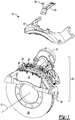
- the brake assembly 10 may be provided with a vehicle, such as a motor vehicle like a truck, bus, farm equipment, military transport or weaponry vehicle, or cargo loading equipment for land, air, or marine vessels.
- the brake assembly 10 may include a housing assembly 20, a first brake pad assembly 22, a second brake pad assembly 24, and at least one brake pad spring 26.
- the brake assembly 10 may include a pad shield in place of, or in addition to, the brake pad spring 26.
- the housing assembly 20 may receive various components of the brake assembly 10.
- the housing assembly 20 may facilitate positioning of the first brake pad assembly 22 and the second brake pad assembly 24 with respect to a rotor 28, also known as a brake disc, to facilitate braking of the vehicle.
- the rotor 28 may define a central axis 12 extending therethrough.
- the housing assembly 20 may include a brake carrier 30, a brake caliper housing (referred to herein as a caliper housing 32), and a caliper bridge 34.
- the brake carrier 30 may be fixedly mounted to the vehicle.
- the brake carrier 30 may be connected to an axle assembly or a steering knuckle, such as with an intermediate component like a torque plate in one or more embodiments.
- the brake carrier 30 may receive and/or support the first brake pad assembly 22 and the second brake pad assembly 24, and may include a rotor opening that may be configured to receive the rotor 28. As such, the brake carrier 30 may straddle the rotor 28 and help position the first brake pad assembly 22 and the second brake pad assembly 24 on opposite sides of the rotor 28.
- the housing assembly 20 may further include a retainer bracket 36.
- the retainer bracket 36 may have a first end that may engage or may be received in a notch in the caliper housing 32 and a second end that may be fixedly disposed on the caliper bridge 34.
- the second end may receive a fastener 38, such as a bolt, that may couple the retainer bracket 36 to the caliper bridge 34.
- the caliper housing 32 may be moveably disposed on the brake carrier 30.
- the caliper housing 32 may be slidably disposed on a pair of guide pins that may be fixedly disposed on the brake carrier 30.
- the caliper housing 32 may be associated with or may receive at least one actuator 42 that may actuate the first brake pad assembly 22 and the second brake pad assembly 24 into engagement with the rotor 28. More specifically, the actuator 42 may actuate the first brake pad assembly 22 into engagement with the rotor 28 and then move the caliper housing 32 and bridge 34 to actuate the second brake pad assembly 24 toward the rotor 28.
- the actuator 42 may have any suitable configuration.
- the actuator may include a piston assembly that may be pneumatically, hydraulically, mechanically, electrically, or electromechanically actuated in one or more embodiments.
- the piston assembly may move along an axis toward or away from the rotor 28 such that the piston assembly may exert force against a back side of the first brake pad assembly 22.
- the caliper housing may be formed from a unitary ("one-piece") cast caliper housing 32.
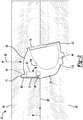
- the cast caliper housing 32 may be formed in a casting assembly 52.
- the casting assembly 52 may include a first die 54 and a second die 56. At least one of the first die 54 and the second die 56 may be moveable along an axis 58, which may be disposed perpendicular to a mating plane 60.
- the first die 54 and the second die 56 may cooperate to define a cavity 62 when disposed against each other along the mating plane 60.
- the mating plane 60 may extend generally perpendicular to the axis 58.
- the first die 54 may engage the second die 56 continuously around the cavity 62 in the mating plane 60.
- molten material may be introduced into the cavity 62.
- One or more inserts and/or cores 64 may be provided in the cavity 62 to form an interior of the cast caliper housing 32.
- the caliper housing 32 may be removed from the first and second dies 54, 56.
- One or more surfaces e.g., surfaces 72, 74
- surfaces 72, 74 may be altered (e.g., machined) such that material is removed from the cast caliper housing 32.
- material may be removed from a surface 72 but not from a boss surface disposed opposite the surface 72 so as to reduce a thickness of a mounting boss.
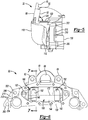
- the caliper housing 32 may include an actuator mounting flange 70.
- the actuator mounting flange 70 may be adapted such that a brake caliper actuator (e.g., actuator 42 of Figure 1 ) may be mounted to the caliper housing 32.
- the actuator mounting flange 70 may include a first surface 80.
- the actuator mounting flange 70 may also include a first mounting boss 82, a second mounting boss 84, and an actuator snout 86 disposed between the first mounting boss 82 and the second mounting boss 84.
- the actuator snout 86 may extend from the first surface 80.
- the first mounting boss 82 may have a first boss surface 92 disposed opposite the first surface 80.
- the second mounting boss 84 may have a second boss surface 94 that may also be disposed opposite the first surface 80. In at least one approach, the first and second boss surfaces 92, 94 are coplanar.
- the first mounting boss 82 may define a first aperture 102.
- the first aperture 102 may extend from the first surface 80 to the first boss surface 92 such that the first aperture 102 may be referred to as a first through hole.
- the second mounting boss 84 may similarly define a second aperture 104.
- the second aperture 104 may extend from the first surface 80 to the second boss surface 94 such that the second aperture may be referred to as a second through hole.
- the first and second apertures 102, 104 may be formed by drilling the first and second mounting bosses 82, 84, respectively. In still another approach, the first and second apertures 102, 104 may be formed during the casting process (e.g., using inserts, cores, or other suitable approaches).
- the actuator mounting flange 70 may be disposed at least partially in the first die 54. In at least one approach, the actuator mounting flange 70 may be disposed completely in the first die 54.
- the first boss surface 92 and the second boss surface 94 may be disposed perpendicular to the mating plane 60, as indicated at 96.
- the caliper housing 32 may have a top surface 120 that may face away from the cavity 62.
- the caliper housing 32 may also have a bottom surface 112 that is disposed opposite the top surface 120 and that also faces away from the cavity 62.
- the top surface 120 and the bottom surface 112 may be disposed in a nonparallel and non-perpendicular relationship with the mating plane 60 and the axis 58.
- a method of making a caliper housing 32 may include removing material from the caliper housing 32 to form the first surface 80. Removing material from the first surface 80 may reduce a thickness of at least a portion of the actuator mounting flange 70.
- material may be removed from the first surface 80 but not from the first boss surface 92. In this way, a thickness of the first mounting boss 82 may be reduced.
- material may be removed from the first surface 80 but not from the second boss surface 94. In this way, a thickness of the second mounting boss 84 may be reduced.
- Removing material from the first surface 80 may also include making the first surface 80 a substantially planar surface.
- the first surface 80 may be machined such that it is parallel with the first boss surface 92, the second boss surface 94, or both the first and second boss surfaces 92, 94.
- first and second mounting bosses 82, 84 may be provided with a machined surface at the first surface 80, and an unmachined surface (e.g., first boss surface 92 and second boss surface 94, respectively).
- An unmachined surface may be a surface that is formed during a casting process (e.g., a sand casting process).
- a machined surface may be a surface that has become exposed, for example, due to a machining process performed after the casting process.
- the machining process may be any process that alters a surface dimension or surface finish.
- Example machine processes may include such as boring, broaching, drilling, electrical discharge machining, electrochemical machining, electron beam machining, milling, photochemical machining, planing, reaming, sawing, shaping, tapping, turning, and ultrasonic machining.
- the different surface finishes may be expressed as having different surface roughness values.
- An unmachined surface may have a surface roughness value greater than 10 micrometers.
- an unmachined surface may have a surface roughness value in the range of approximately 12 micrometers to approximately 25 micrometers.
- a machined surface may have a surface roughness value less than or equal to 10 micrometers.
- a machined surface may have a surface roughness value in the range of approximately 5 micrometers to approximately 7 micrometers.
- the caliper housing 32 may include a rear surface 110.
- the rear surface 110 may extend from the first surface 80 to a lower surface 112 of the caliper housing 32.
- the rear surface 110 may be disposed in a nonparallel relationship with the first surface 80.
- the rear surface 110 may be disposed perpendicular, or substantially perpendicular (e.g., within +/- 5°), to the lower surface 112.
- the caliper housing 32 may include a first upper surface 120, and may include a second upper surface 122.
- the first and second upper surfaces 120, 122 may be disposed opposite the lower surface 112.
- the first upper surface 120 may be disposed at an acute angle with the first mounting boss 82, as indicated at 124.
- the second upper surface 122 may be disposed at an acute angle with the second mounting boss 84.
- the actuator snout 86 may be disposed between the first and second upper surfaces 120, 122.
- the caliper housing 32 may further include an interface wall 130.
- the interface wall 130 may be disposed opposite the rear surface 110 and may be disposed in a parallel, or substantially parallel (e.g., within +/- 5°), relationship with the rear surface 110. In at least on approach, the interface wall 130 may be disposed in a nonparallel relationship with the first boss surface 92, the second boss surface 94, or both the first and the second boss surfaces 92, 94.
- the interface wall 130 may define an opening 132 that may permit one or more internal components (e.g., pistons) disposed within the caliper housing 32 to interact with one or more brake pad assemblies.
- the caliper housing 32 may include a first end wall 140, a second end wall 142 that may be disposed opposite the first end wall 140, and a transverse wall 144 that extends from the first end wall 140 to the second end wall 142.
- the second end wall 142 may extend at least partially in a plane that is parallel to the first end wall 140.
- the first and second end walls 140, 142 may extend orthogonally from the transverse wall 144.
- the interface wall 130 may extend from the first end wall 140, the second end wall 142, and the transverse wall 144.
- the interface wall 130 may cooperate with the first end wall 140, the second end wall 142, and the transverse wall 144 to at least partially define a cavity 150.
- the interface wall 130 may define the opening 132 of the cavity 150.
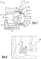
- a first bearing protrusion 160 may extend from the first end wall 140 and the transverse wall 144.
- the first bearing protrusion 160 may define a first lateral bearing surface 162 that may be disposed, for example, substantially parallel to the first end wall 140.
- the first bearing protrusion 160 may further define a first arcuate bearing surface 164 that may extend, for example, from the first lateral bearing surface 162.
- the first lateral bearing surface 162 may intersect the first arcuate bearing surface 164 along a continuously curved line 166, as indicated in Figure 8 .
- the first lateral bearing surface 162 and the first arcuate bearing surface 164 of the first bearing protrusion 160 may be adapted to rotatably support an operating shaft 170, indicated schematically in Figure 7 .
- the first lateral bearing surface 162 may be spaced apart from the first end wall 140.
- the first arcuate bearing surface 164 may be spaced apart from the transverse wall 144. In this way, support surfaces of the first lateral bearing surface 162 and the first arcuate bearing surface 164 may be offset from the first end wall 140 and the transverse wall 144, respectively.
- a transverse axis 172 may intersect the first end wall 140 and the second end wall 142.
- the transverse axis 172 may be parallel to a central axis of the operating shaft 170.
- the transverse axis 172 may be coaxial with the central axis of the operating shaft 170.
- the first arcuate bearing surface 164 may be radially disposed with respect to the transverse axis 172.
- the first lateral bearing surface 162 may be disposed perpendicular to the transverse axis 172.
- the first bearing protrusion 160 may be completely disposed below the transverse axis 172.
- the caliper housing 32 may further include a second bearing protrusion 180.
- the second bearing protrusion 180 may extend from the first end wall 140.
- the second bearing protrusion 180 may be disposed opposite the transverse axis 172 from the first bearing protrusion 160, and may extend toward the first bearing protrusion 160.
- the second bearing protrusion 180 may be completely disposed above the transverse axis 172.
- the second bearing protrusion 180 may define a second lateral bearing surface 182 and a second arcuate bearing surface 184.
- the second lateral bearing surface 182 may be spaced apart from the first end wall 140.
- the second arcuate bearing surface 184 may be spaced apart from the transverse wall 144.
- the second lateral bearing surface 182 may be disposed substantially parallel to the first end wall 140.
- the second arcuate bearing surface 184 may extend from the second lateral bearing surface 182.
- the second lateral bearing surface 182 and the second arcuate bearing surface 184 may be adapted to support the operating shaft 170.
- the caliper housing 32 may further include an upper surface 190.
- the second bearing protrusion 180 may extend from the upper surface 190 toward the first bearing protrusion 160.
- the first lateral bearing surface 162 may be parallel to the second lateral bearing surface 182.
- the first lateral bearing surface 162 may be coplanar with the second lateral bearing surface 182.
- the second arcuate bearing surface 184 may be radially disposed with respect to the transverse axis 172. As such, the first arcuate bearing surface 164 and the second arcuate bearing surface 184 may be disposed a common radial distance R from the transverse axis 172.
- the caliper housing 32 includes at least one saddle bearing protrusion 192.
- the saddle bearing protrusion 192 may extend from the transverse wall 144.
- the first bearing protrusion 160 may be axially disposed between the saddle bearing protrusion 192 and the first end wall 140.
- the second bearing protrusion 180 may also be axially disposed between the saddle bearing protrusion 192 and the first end wall 140.
- the caliper housing 32 may further include a first mounting pad 200 and a second mounting pad 202.
- the second mounting pad 202 may be spaced apart from the first mounting pad 200.
- the first mounting pad 200 and the second mounting pad 202 may extend perpendicular with respect to each other.
- first and second mounting pads 200, 202 may define a hole 204, 206.
- the holes 204, 206 may be through holes that may extend through the each of the first mounting pad 200 and the second mounting pad 202, respectively.
- the holes 204, 206 may be adapted to receive a fastener for mounting a bridge (e.g., bridge 34 of Figure 1 ) to the caliper housing 32.
Landscapes
- Engineering & Computer Science (AREA)
- General Engineering & Computer Science (AREA)
- Mechanical Engineering (AREA)
- Braking Arrangements (AREA)
Claims (15)
- Bremssattelgehäuse (32), das Folgendes umfasst:eine erste Endwand (140);eine zweite Endwand (142), die gegenüber der ersten Endwand (140) angeordnet ist;eine Querwand (144), die sich von der ersten Endwand (140) zu der zweiten Endwand (142) erstreckt;eine Schnittstellenwand (130), die sich von der ersten Endwand (140), der zweiten Endwand (142) und der Querwand (144) erstreckt, wobei die Schnittstellenwand (130) mit der ersten Endwand (140), der zweiten Endwand (142) und der Querwand (144) dahingehend zusammenwirkt, zumindest zum Teil einen Hohlraum (150) zu definieren, und wobei die Schnittstellenwand (130) eine Öffnung (132) des Hohlraums (150) definiert;einen ersten Lagervorsprung (160), der sich von der ersten Endwand (140) und der Querwand (144) erstreckt, wobei der erste Lagervorsprung (160) eine erste laterale Lagerfläche (162), die im Wesentlichen parallel zur ersten Endwand (140) angeordnet ist, und eine erste bogenförmige Lagerfläche (164), die sich von der ersten laterale Lagerfläche (162) erstreckt, umfasst,dadurch gekennzeichnet, dasseinen zweiten Lagervorsprung (180), der sich von der ersten Endwand (140) erstreckt, wobei der zweite Lagervorsprung (180) eine zweite laterale Lagerfläche (182), die im Wesentlichen parallel zu der ersten Endwand (140) angeordnet ist, und eine zweite bogenförmige Lagerfläche (184), die sich von der zweiten laterale Lagerfläche (182) erstreckt, definiert, wobei die erste laterale Lagerfläche (162) und die zweite laterale Lagerfläche (182) dazu ausgeführt sind, eine Betätigungswelle (170) zu stützen.
- Bremssattelgehäuse (32) nach Anspruch 1, wobei die erste laterale Lagerfläche (162) von der ersten Endwand (140) beabstandet ist.
- Bremssattelgehäuse (32) nach einem vorhergehenden Anspruch, wobei die erste bogenförmige Lagerfläche (164) von der Querwand (144) beabstandet ist.
- Bremssattelgehäuse (32) nach einem vorhergehenden Anspruch, wobei die erste bogenförmige Lagerfläche (164) radial bezüglich einer Querachse (172), die die erste Endwand (140) und die zweite Endwand (142) schneidet, angeordnet ist und/oder der erste Lagervorsprung (160) unterhalb der Querachse (172) angeordnet ist.
- Bremssattelgehäuse (32) nach Anspruch 4, wobei die erste laterale Lagerfläche (162) senkrecht zur Querachse (172) angeordnet ist, vorzugsweise schneidet die erste laterale Lagerfläche (162) die erste bogenförmige Lagerfläche (164) entlang einer durchgängig gekrümmten Linie (166).
- Bremssattelgehäuse (32) nach einem vorhergehenden Anspruch, wobei der zweite Lagervorsprung (180) komplett oberhalb der Querachse (172) angeordnet ist.
- Bremssattelgehäuse (32) nach einem vorhergehenden Anspruch, wobei die zweite laterale Lagerfläche (182) von der ersten Endwand (140) beabstandet ist.
- Bremssattelgehäuse (32) nach einem vorhergehenden Anspruch, wobei die zweite bogenförmige Lagerfläche (184) von der Querwand (144) beabstandet ist und/oder die erste bogenförmige Lagerfläche (164) die zweite bogenförmige Lagerfläche (184) in einem gemeinsamen radialen Abstand zur Querachse (172) angeordnet sind.
- Bremssattelgehäuse (32) nach einem vorhergehenden Anspruch, das ferner eine obere Fläche (190) umfasst, wobei sich der zweite Lagervorsprung (180) von der oberen Fläche (190) zu dem ersten Lagervorsprung (160) erstreckt.
- Bremssattelgehäuse (32) nach einem vorhergehenden Anspruch, wobei die erste laterale Lagerfläche (162) parallel zur zweiten lateralen Lagerfläche (182) ist, vorzugsweise ist die erste laterale Lagerfläche (162) koplanar mit der zweiten lateralen Lagerfläche (182) .
- Bremssattelgehäuse (32) nach einem vorhergehenden Anspruch, wobei sich ein erster Sattellagervorsprung (192) von der Querwand (144) erstreckt und der erste Lagervorsprung (160) axial zwischen dem ersten Sattellagervorsprung (192) und der ersten Endwand (140) angeordnet ist.
- Bremssattelgehäuse (32) nach Anspruch 11, das ferner einen zweiten Sattellagervorsprung (192) umfasst, der sich von der Querwand (144) erstreckt, und der zweite Vorsprung (180) axial zwischen dem ersten Sattellagervorsprung (192) und der ersten Endwand (140) angeordnet ist.
- Bremssattelgehäuse (32) nach einem vorhergehenden Anspruch, das ferner ein erstes Befestigungspad (200) und ein zweites Befestigungspad (202), das von dem ersten Befestigungspad (200) beabstandet ist, umfasst, wobei sich eine Durchgangsbohrung (204, 206), die dazu ausgeführt ist, ein Befestigungsmittel zur Befestigung einer Brücke (34) an dem Bremssattelgehäuse (32) aufzunehmen, durch sowohl das erste Befestigungspad (200) als auch das zweite Befestigungspad (202) erstreckt.
- Bremssattelgehäuse (32) nach Anspruch 13, das ferner eine Verbindungsfläche (210) umfasst, die sich von dem ersten Befestigungspad (200) zu dem zweiten Befestigungspad (202) erstreckt, wobei die Verbindungsfläche (210) von der Brücke (34) beabstandet ist, wobei sich vorzugsweise das erste Befestigungspad (200) und das zweite Befestigungspad (202) senkrecht zueinander erstrecken.
- Bremssattelgehäuse (32) nach Anspruch 14, das ferner eine Stufenfläche (212) umfasst, die sich von der Verbindungsfläche (210) zu dem ersten Befestigungspad (200) und dem zweiten Befestigungspad (202) erstreckt.
Applications Claiming Priority (1)
| Application Number | Priority Date | Filing Date | Title |
|---|---|---|---|
| US15/910,423 US10648522B2 (en) | 2018-03-02 | 2018-03-02 | Brake caliper housing |
Publications (2)
| Publication Number | Publication Date |
|---|---|
| EP3534028A1 EP3534028A1 (de) | 2019-09-04 |
| EP3534028B1 true EP3534028B1 (de) | 2020-10-28 |
Family
ID=65138853
Family Applications (1)
| Application Number | Title | Priority Date | Filing Date |
|---|---|---|---|
| EP19152715.9A Active EP3534028B1 (de) | 2018-03-02 | 2019-01-21 | Bremssattelgehäuse |
Country Status (3)
| Country | Link |
|---|---|
| US (1) | US10648522B2 (de) |
| EP (1) | EP3534028B1 (de) |
| CN (1) | CN110219907B (de) |
Families Citing this family (3)
| Publication number | Priority date | Publication date | Assignee | Title |
|---|---|---|---|---|
| USD894066S1 (en) * | 2018-06-20 | 2020-08-25 | Mann+Hummel Gmbh | Brake dust filter |
| CN114008346B (zh) * | 2019-06-19 | 2025-02-18 | 采埃孚商用车系统欧洲有限公司 | 车辆制动器、尤其是商用车辆压缩空气盘式制动器以及用于其的压块 |
| US20250075756A1 (en) * | 2023-09-01 | 2025-03-06 | Arvinmeritor Technology, Llc | Single piston brake caliper housing and a method of manufacturing a single piston brake caliper housing |
Family Cites Families (10)
| Publication number | Priority date | Publication date | Assignee | Title |
|---|---|---|---|---|
| DE4430258C1 (de) | 1994-08-25 | 1996-01-04 | Perrot Bremsen Gmbh | Zuspannvorrichtung für eine Scheibenbremse |
| DE10106591C1 (de) | 2001-02-13 | 2002-08-14 | Lucas Automotive Gmbh | Verfahren zum spanlosen Formen und anschließenden spanenden Nachbearbeiten eines Bremssattels |
| SE523555C2 (sv) | 2001-09-07 | 2004-04-27 | Haldex Brake Prod Ab | Modulformad skrivbroms för ett fordon |
| JP5126786B2 (ja) * | 2008-07-11 | 2013-01-23 | 曙ブレーキ工業株式会社 | ディスクブレーキ装置用パッドクリップ |
| DE102008035753A1 (de) * | 2008-07-31 | 2010-02-04 | Wabco Radbremsen Gmbh | Verfahren zum Herstellen eines Bremssattels, Bearbeitungswerkzeug zum Ausführen des Verfahrens, mit dem Verfahren hergestellter Bremssattel sowie Scheibenbremse mit einem solchen Sattel |
| US8161614B2 (en) | 2009-03-20 | 2012-04-24 | Bendix Spicer Foundation Brake Llc | Air disk brake caliper pre-stressing method and pre-stressed caliper apparatus |
| WO2012069069A1 (de) | 2010-11-26 | 2012-05-31 | Wabco Radbremsen Gmbh | Scheibenbremse |
| US8857575B2 (en) | 2012-12-11 | 2014-10-14 | Arvinmeritor Technology, Llc | Brake caliper assembly having a pad shield |
| US9068610B2 (en) | 2012-12-11 | 2015-06-30 | Arvinmeritor Technology, Llc | Brake caliper assembly having a spacer tape and a method of manufacture |
| EP3121477B1 (de) | 2015-07-21 | 2022-10-05 | Meritor Heavy Vehicle Braking Systems (UK) Limited | Scheibenbremsanordnung |
-
2018
- 2018-03-02 US US15/910,423 patent/US10648522B2/en active Active
- 2018-10-12 CN CN201811187697.2A patent/CN110219907B/zh active Active
-
2019
- 2019-01-21 EP EP19152715.9A patent/EP3534028B1/de active Active
Non-Patent Citations (1)
| Title |
|---|
| None * |
Also Published As
| Publication number | Publication date |
|---|---|
| CN110219907B (zh) | 2021-11-23 |
| US20190271369A1 (en) | 2019-09-05 |
| CN110219907A (zh) | 2019-09-10 |
| US10648522B2 (en) | 2020-05-12 |
| EP3534028A1 (de) | 2019-09-04 |
Similar Documents
| Publication | Publication Date | Title |
|---|---|---|
| EP3534028B1 (de) | Bremssattelgehäuse | |
| US7797812B2 (en) | Method of manufacturing a disc brake | |
| EP1729980B1 (de) | Radnabe mit verbesserter führungsvorrichtung und verfahren zur herstellung | |
| ES8700176A1 (es) | Perfeccionamientos introducidos en un conjunto de rotula de direccion para un vehiculo de motor. | |
| EP3533531B1 (de) | Bremssattelgehäuse und verfahren zur herstellung | |
| EP1462671A1 (de) | Einstückiger Schwimmsattel für eine Bremse | |
| EP1516132B1 (de) | Bremsdrehmomentplatte und installationsverfahren | |
| EP3492770B1 (de) | Bremsträger und verfahren zur herstellung | |
| EP1586787A1 (de) | Einstückiger Gleitbremssattel. | |
| EP4542077A1 (de) | Sattelscheibenbremse und fahrzeug damit | |
| US20130270048A1 (en) | Brake calliper for a vehicle brake system and method and device for producing a brake calliper | |
| DE102005024345A1 (de) | Fahrzeugrad mit einer gefrästen Ablaufnut | |
| EP0636219B1 (de) | Methode zur herstellung eines hydraulischen stellorgans | |
| US20210246954A1 (en) | Brake Mounting Bracket | |
| JP3289173B2 (ja) | 車両用ディスクブレーキにおけるキャリパボディの製造方法 | |
| US7003952B2 (en) | Master cylinder and method of producing the same | |
| CN110090968A (zh) | 一种制动鼓机加工工艺 | |
| EP4616988A1 (de) | Scheibenbremse und sattelkörper | |
| CN223590477U (zh) | 托板及其制成的桥壳总成 | |
| JP3344729B2 (ja) | ディスクブレーキ | |
| US20250075756A1 (en) | Single piston brake caliper housing and a method of manufacturing a single piston brake caliper housing | |
| JPH04356266A (ja) | 鋳物製マスタシリンダ | |
| EP2765323A1 (de) | Bremsgrundplatte mit feiner Kante | |
| JPH06298115A (ja) | 一体型ステアリングナックルアセンブリ | |
| JP2014040881A (ja) | 車両のブレーキドラム及びその製造方法 |
Legal Events
| Date | Code | Title | Description |
|---|---|---|---|
| PUAI | Public reference made under article 153(3) epc to a published international application that has entered the european phase |
Free format text: ORIGINAL CODE: 0009012 |
|
| STAA | Information on the status of an ep patent application or granted ep patent |
Free format text: STATUS: THE APPLICATION HAS BEEN PUBLISHED |
|
| AK | Designated contracting states |
Kind code of ref document: A1 Designated state(s): AL AT BE BG CH CY CZ DE DK EE ES FI FR GB GR HR HU IE IS IT LI LT LU LV MC MK MT NL NO PL PT RO RS SE SI SK SM TR |
|
| AX | Request for extension of the european patent |
Extension state: BA ME |
|
| STAA | Information on the status of an ep patent application or granted ep patent |
Free format text: STATUS: REQUEST FOR EXAMINATION WAS MADE |
|
| 17P | Request for examination filed |
Effective date: 20200302 |
|
| RBV | Designated contracting states (corrected) |
Designated state(s): AL AT BE BG CH CY CZ DE DK EE ES FI FR GB GR HR HU IE IS IT LI LT LU LV MC MK MT NL NO PL PT RO RS SE SI SK SM TR |
|
| GRAP | Despatch of communication of intention to grant a patent |
Free format text: ORIGINAL CODE: EPIDOSNIGR1 |
|
| STAA | Information on the status of an ep patent application or granted ep patent |
Free format text: STATUS: GRANT OF PATENT IS INTENDED |
|
| RIC1 | Information provided on ipc code assigned before grant |
Ipc: F16D 65/00 20060101AFI20200512BHEP |
|
| INTG | Intention to grant announced |
Effective date: 20200605 |
|
| GRAS | Grant fee paid |
Free format text: ORIGINAL CODE: EPIDOSNIGR3 |
|
| GRAA | (expected) grant |
Free format text: ORIGINAL CODE: 0009210 |
|
| STAA | Information on the status of an ep patent application or granted ep patent |
Free format text: STATUS: THE PATENT HAS BEEN GRANTED |
|
| AK | Designated contracting states |
Kind code of ref document: B1 Designated state(s): AL AT BE BG CH CY CZ DE DK EE ES FI FR GB GR HR HU IE IS IT LI LT LU LV MC MK MT NL NO PL PT RO RS SE SI SK SM TR |
|
| REG | Reference to a national code |
Ref country code: GB Ref legal event code: FG4D |
|
| REG | Reference to a national code |
Ref country code: CH Ref legal event code: EP |
|
| REG | Reference to a national code |
Ref country code: DE Ref legal event code: R096 Ref document number: 602019001045 Country of ref document: DE |
|
| REG | Reference to a national code |
Ref country code: AT Ref legal event code: REF Ref document number: 1328549 Country of ref document: AT Kind code of ref document: T Effective date: 20201115 |
|
| REG | Reference to a national code |
Ref country code: IE Ref legal event code: FG4D |
|
| REG | Reference to a national code |
Ref country code: SE Ref legal event code: TRGR |
|
| REG | Reference to a national code |
Ref country code: AT Ref legal event code: MK05 Ref document number: 1328549 Country of ref document: AT Kind code of ref document: T Effective date: 20201028 |
|
| REG | Reference to a national code |
Ref country code: NL Ref legal event code: MP Effective date: 20201028 |
|
| PG25 | Lapsed in a contracting state [announced via postgrant information from national office to epo] |
Ref country code: GR Free format text: LAPSE BECAUSE OF FAILURE TO SUBMIT A TRANSLATION OF THE DESCRIPTION OR TO PAY THE FEE WITHIN THE PRESCRIBED TIME-LIMIT Effective date: 20210129 Ref country code: NO Free format text: LAPSE BECAUSE OF FAILURE TO SUBMIT A TRANSLATION OF THE DESCRIPTION OR TO PAY THE FEE WITHIN THE PRESCRIBED TIME-LIMIT Effective date: 20210128 Ref country code: FI Free format text: LAPSE BECAUSE OF FAILURE TO SUBMIT A TRANSLATION OF THE DESCRIPTION OR TO PAY THE FEE WITHIN THE PRESCRIBED TIME-LIMIT Effective date: 20201028 Ref country code: RS Free format text: LAPSE BECAUSE OF FAILURE TO SUBMIT A TRANSLATION OF THE DESCRIPTION OR TO PAY THE FEE WITHIN THE PRESCRIBED TIME-LIMIT Effective date: 20201028 Ref country code: PT Free format text: LAPSE BECAUSE OF FAILURE TO SUBMIT A TRANSLATION OF THE DESCRIPTION OR TO PAY THE FEE WITHIN THE PRESCRIBED TIME-LIMIT Effective date: 20210301 |
|
| REG | Reference to a national code |
Ref country code: LT Ref legal event code: MG4D |
|
| PG25 | Lapsed in a contracting state [announced via postgrant information from national office to epo] |
Ref country code: IS Free format text: LAPSE BECAUSE OF FAILURE TO SUBMIT A TRANSLATION OF THE DESCRIPTION OR TO PAY THE FEE WITHIN THE PRESCRIBED TIME-LIMIT Effective date: 20210228 Ref country code: LV Free format text: LAPSE BECAUSE OF FAILURE TO SUBMIT A TRANSLATION OF THE DESCRIPTION OR TO PAY THE FEE WITHIN THE PRESCRIBED TIME-LIMIT Effective date: 20201028 Ref country code: PL Free format text: LAPSE BECAUSE OF FAILURE TO SUBMIT A TRANSLATION OF THE DESCRIPTION OR TO PAY THE FEE WITHIN THE PRESCRIBED TIME-LIMIT Effective date: 20201028 Ref country code: BG Free format text: LAPSE BECAUSE OF FAILURE TO SUBMIT A TRANSLATION OF THE DESCRIPTION OR TO PAY THE FEE WITHIN THE PRESCRIBED TIME-LIMIT Effective date: 20210128 Ref country code: ES Free format text: LAPSE BECAUSE OF FAILURE TO SUBMIT A TRANSLATION OF THE DESCRIPTION OR TO PAY THE FEE WITHIN THE PRESCRIBED TIME-LIMIT Effective date: 20201028 Ref country code: AT Free format text: LAPSE BECAUSE OF FAILURE TO SUBMIT A TRANSLATION OF THE DESCRIPTION OR TO PAY THE FEE WITHIN THE PRESCRIBED TIME-LIMIT Effective date: 20201028 |
|
| PG25 | Lapsed in a contracting state [announced via postgrant information from national office to epo] |
Ref country code: HR Free format text: LAPSE BECAUSE OF FAILURE TO SUBMIT A TRANSLATION OF THE DESCRIPTION OR TO PAY THE FEE WITHIN THE PRESCRIBED TIME-LIMIT Effective date: 20201028 Ref country code: NL Free format text: LAPSE BECAUSE OF FAILURE TO SUBMIT A TRANSLATION OF THE DESCRIPTION OR TO PAY THE FEE WITHIN THE PRESCRIBED TIME-LIMIT Effective date: 20201028 |
|
| REG | Reference to a national code |
Ref country code: DE Ref legal event code: R097 Ref document number: 602019001045 Country of ref document: DE |
|
| PG25 | Lapsed in a contracting state [announced via postgrant information from national office to epo] |
Ref country code: RO Free format text: LAPSE BECAUSE OF FAILURE TO SUBMIT A TRANSLATION OF THE DESCRIPTION OR TO PAY THE FEE WITHIN THE PRESCRIBED TIME-LIMIT Effective date: 20201028 Ref country code: LT Free format text: LAPSE BECAUSE OF FAILURE TO SUBMIT A TRANSLATION OF THE DESCRIPTION OR TO PAY THE FEE WITHIN THE PRESCRIBED TIME-LIMIT Effective date: 20201028 Ref country code: CZ Free format text: LAPSE BECAUSE OF FAILURE TO SUBMIT A TRANSLATION OF THE DESCRIPTION OR TO PAY THE FEE WITHIN THE PRESCRIBED TIME-LIMIT Effective date: 20201028 Ref country code: EE Free format text: LAPSE BECAUSE OF FAILURE TO SUBMIT A TRANSLATION OF THE DESCRIPTION OR TO PAY THE FEE WITHIN THE PRESCRIBED TIME-LIMIT Effective date: 20201028 Ref country code: SK Free format text: LAPSE BECAUSE OF FAILURE TO SUBMIT A TRANSLATION OF THE DESCRIPTION OR TO PAY THE FEE WITHIN THE PRESCRIBED TIME-LIMIT Effective date: 20201028 Ref country code: SM Free format text: LAPSE BECAUSE OF FAILURE TO SUBMIT A TRANSLATION OF THE DESCRIPTION OR TO PAY THE FEE WITHIN THE PRESCRIBED TIME-LIMIT Effective date: 20201028 |
|
| PG25 | Lapsed in a contracting state [announced via postgrant information from national office to epo] |
Ref country code: DK Free format text: LAPSE BECAUSE OF FAILURE TO SUBMIT A TRANSLATION OF THE DESCRIPTION OR TO PAY THE FEE WITHIN THE PRESCRIBED TIME-LIMIT Effective date: 20201028 Ref country code: MC Free format text: LAPSE BECAUSE OF FAILURE TO SUBMIT A TRANSLATION OF THE DESCRIPTION OR TO PAY THE FEE WITHIN THE PRESCRIBED TIME-LIMIT Effective date: 20201028 |
|
| PLBE | No opposition filed within time limit |
Free format text: ORIGINAL CODE: 0009261 |
|
| STAA | Information on the status of an ep patent application or granted ep patent |
Free format text: STATUS: NO OPPOSITION FILED WITHIN TIME LIMIT |
|
| PG25 | Lapsed in a contracting state [announced via postgrant information from national office to epo] |
Ref country code: LU Free format text: LAPSE BECAUSE OF NON-PAYMENT OF DUE FEES Effective date: 20210121 |
|
| 26N | No opposition filed |
Effective date: 20210729 |
|
| REG | Reference to a national code |
Ref country code: BE Ref legal event code: MM Effective date: 20210131 |
|
| PG25 | Lapsed in a contracting state [announced via postgrant information from national office to epo] |
Ref country code: AL Free format text: LAPSE BECAUSE OF FAILURE TO SUBMIT A TRANSLATION OF THE DESCRIPTION OR TO PAY THE FEE WITHIN THE PRESCRIBED TIME-LIMIT Effective date: 20201028 Ref country code: IT Free format text: LAPSE BECAUSE OF FAILURE TO SUBMIT A TRANSLATION OF THE DESCRIPTION OR TO PAY THE FEE WITHIN THE PRESCRIBED TIME-LIMIT Effective date: 20201028 |
|
| PG25 | Lapsed in a contracting state [announced via postgrant information from national office to epo] |
Ref country code: SI Free format text: LAPSE BECAUSE OF FAILURE TO SUBMIT A TRANSLATION OF THE DESCRIPTION OR TO PAY THE FEE WITHIN THE PRESCRIBED TIME-LIMIT Effective date: 20201028 |
|
| PG25 | Lapsed in a contracting state [announced via postgrant information from national office to epo] |
Ref country code: IE Free format text: LAPSE BECAUSE OF NON-PAYMENT OF DUE FEES Effective date: 20210121 |
|
| PG25 | Lapsed in a contracting state [announced via postgrant information from national office to epo] |
Ref country code: IS Free format text: LAPSE BECAUSE OF FAILURE TO SUBMIT A TRANSLATION OF THE DESCRIPTION OR TO PAY THE FEE WITHIN THE PRESCRIBED TIME-LIMIT Effective date: 20210228 |
|
| PG25 | Lapsed in a contracting state [announced via postgrant information from national office to epo] |
Ref country code: BE Free format text: LAPSE BECAUSE OF NON-PAYMENT OF DUE FEES Effective date: 20210131 |
|
| REG | Reference to a national code |
Ref country code: CH Ref legal event code: PL |
|
| PG25 | Lapsed in a contracting state [announced via postgrant information from national office to epo] |
Ref country code: LI Free format text: LAPSE BECAUSE OF NON-PAYMENT OF DUE FEES Effective date: 20220131 Ref country code: CH Free format text: LAPSE BECAUSE OF NON-PAYMENT OF DUE FEES Effective date: 20220131 |
|
| PG25 | Lapsed in a contracting state [announced via postgrant information from national office to epo] |
Ref country code: CY Free format text: LAPSE BECAUSE OF FAILURE TO SUBMIT A TRANSLATION OF THE DESCRIPTION OR TO PAY THE FEE WITHIN THE PRESCRIBED TIME-LIMIT Effective date: 20201028 |
|
| P01 | Opt-out of the competence of the unified patent court (upc) registered |
Effective date: 20230531 |
|
| PG25 | Lapsed in a contracting state [announced via postgrant information from national office to epo] |
Ref country code: HU Free format text: LAPSE BECAUSE OF FAILURE TO SUBMIT A TRANSLATION OF THE DESCRIPTION OR TO PAY THE FEE WITHIN THE PRESCRIBED TIME-LIMIT; INVALID AB INITIO Effective date: 20190121 |
|
| GBPC | Gb: european patent ceased through non-payment of renewal fee |
Effective date: 20230121 |
|
| PG25 | Lapsed in a contracting state [announced via postgrant information from national office to epo] |
Ref country code: GB Free format text: LAPSE BECAUSE OF NON-PAYMENT OF DUE FEES Effective date: 20230121 |
|
| PG25 | Lapsed in a contracting state [announced via postgrant information from national office to epo] |
Ref country code: MK Free format text: LAPSE BECAUSE OF FAILURE TO SUBMIT A TRANSLATION OF THE DESCRIPTION OR TO PAY THE FEE WITHIN THE PRESCRIBED TIME-LIMIT Effective date: 20201028 |
|
| PG25 | Lapsed in a contracting state [announced via postgrant information from national office to epo] |
Ref country code: TR Free format text: LAPSE BECAUSE OF FAILURE TO SUBMIT A TRANSLATION OF THE DESCRIPTION OR TO PAY THE FEE WITHIN THE PRESCRIBED TIME-LIMIT Effective date: 20201028 |
|
| PG25 | Lapsed in a contracting state [announced via postgrant information from national office to epo] |
Ref country code: MT Free format text: LAPSE BECAUSE OF FAILURE TO SUBMIT A TRANSLATION OF THE DESCRIPTION OR TO PAY THE FEE WITHIN THE PRESCRIBED TIME-LIMIT Effective date: 20201028 |
|
| PGFP | Annual fee paid to national office [announced via postgrant information from national office to epo] |
Ref country code: SE Payment date: 20260127 Year of fee payment: 8 |
|
| PGFP | Annual fee paid to national office [announced via postgrant information from national office to epo] |
Ref country code: DE Payment date: 20260128 Year of fee payment: 8 |
|
| PGFP | Annual fee paid to national office [announced via postgrant information from national office to epo] |
Ref country code: FR Payment date: 20260126 Year of fee payment: 8 |