EP3533650A1 - Kraftstoffbefüllvorrichtung - Google Patents
Kraftstoffbefüllvorrichtung Download PDFInfo
- Publication number
- EP3533650A1 EP3533650A1 EP18159688.3A EP18159688A EP3533650A1 EP 3533650 A1 EP3533650 A1 EP 3533650A1 EP 18159688 A EP18159688 A EP 18159688A EP 3533650 A1 EP3533650 A1 EP 3533650A1
- Authority
- EP
- European Patent Office
- Prior art keywords
- attachment
- fuel
- flow
- flow guide
- filling device
- Prior art date
- Legal status (The legal status is an assumption and is not a legal conclusion. Google has not performed a legal analysis and makes no representation as to the accuracy of the status listed.)
- Granted
Links
Images
Classifications
-
- B—PERFORMING OPERATIONS; TRANSPORTING
- B67—OPENING, CLOSING OR CLEANING BOTTLES, JARS OR SIMILAR CONTAINERS; LIQUID HANDLING
- B67D—DISPENSING, DELIVERING OR TRANSFERRING LIQUIDS, NOT OTHERWISE PROVIDED FOR
- B67D7/00—Apparatus or devices for transferring liquids from bulk storage containers or reservoirs into vehicles or into portable containers, e.g. for retail sale purposes
- B67D7/06—Details or accessories
- B67D7/42—Filling nozzles
- B67D7/54—Filling nozzles with means for preventing escape of liquid or vapour or for recovering escaped liquid or vapour
-
- B—PERFORMING OPERATIONS; TRANSPORTING
- B60—VEHICLES IN GENERAL
- B60K—ARRANGEMENT OR MOUNTING OF PROPULSION UNITS OR OF TRANSMISSIONS IN VEHICLES; ARRANGEMENT OR MOUNTING OF PLURAL DIVERSE PRIME-MOVERS IN VEHICLES; AUXILIARY DRIVES FOR VEHICLES; INSTRUMENTATION OR DASHBOARDS FOR VEHICLES; ARRANGEMENTS IN CONNECTION WITH COOLING, AIR INTAKE, GAS EXHAUST OR FUEL SUPPLY OF PROPULSION UNITS IN VEHICLES
- B60K15/00—Arrangement in connection with fuel supply of combustion engines or other fuel consuming energy converters, e.g. fuel cells; Mounting or construction of fuel tanks
- B60K15/03—Fuel tanks
- B60K15/04—Tank inlets
-
- B—PERFORMING OPERATIONS; TRANSPORTING
- B60—VEHICLES IN GENERAL
- B60K—ARRANGEMENT OR MOUNTING OF PROPULSION UNITS OR OF TRANSMISSIONS IN VEHICLES; ARRANGEMENT OR MOUNTING OF PLURAL DIVERSE PRIME-MOVERS IN VEHICLES; AUXILIARY DRIVES FOR VEHICLES; INSTRUMENTATION OR DASHBOARDS FOR VEHICLES; ARRANGEMENTS IN CONNECTION WITH COOLING, AIR INTAKE, GAS EXHAUST OR FUEL SUPPLY OF PROPULSION UNITS IN VEHICLES
- B60K15/00—Arrangement in connection with fuel supply of combustion engines or other fuel consuming energy converters, e.g. fuel cells; Mounting or construction of fuel tanks
- B60K15/03—Fuel tanks
- B60K2015/03328—Arrangements or special measures related to fuel tanks or fuel handling
- B60K2015/03394—Arrangements or special measures related to fuel tanks or fuel handling for preventing expulsion of fuel during filling of the tank
-
- B—PERFORMING OPERATIONS; TRANSPORTING
- B60—VEHICLES IN GENERAL
- B60K—ARRANGEMENT OR MOUNTING OF PROPULSION UNITS OR OF TRANSMISSIONS IN VEHICLES; ARRANGEMENT OR MOUNTING OF PLURAL DIVERSE PRIME-MOVERS IN VEHICLES; AUXILIARY DRIVES FOR VEHICLES; INSTRUMENTATION OR DASHBOARDS FOR VEHICLES; ARRANGEMENTS IN CONNECTION WITH COOLING, AIR INTAKE, GAS EXHAUST OR FUEL SUPPLY OF PROPULSION UNITS IN VEHICLES
- B60K15/00—Arrangement in connection with fuel supply of combustion engines or other fuel consuming energy converters, e.g. fuel cells; Mounting or construction of fuel tanks
- B60K15/03—Fuel tanks
- B60K2015/03328—Arrangements or special measures related to fuel tanks or fuel handling
- B60K2015/0344—Arrangements or special measures related to fuel tanks or fuel handling comprising baffles
-
- B—PERFORMING OPERATIONS; TRANSPORTING
- B60—VEHICLES IN GENERAL
- B60K—ARRANGEMENT OR MOUNTING OF PROPULSION UNITS OR OF TRANSMISSIONS IN VEHICLES; ARRANGEMENT OR MOUNTING OF PLURAL DIVERSE PRIME-MOVERS IN VEHICLES; AUXILIARY DRIVES FOR VEHICLES; INSTRUMENTATION OR DASHBOARDS FOR VEHICLES; ARRANGEMENTS IN CONNECTION WITH COOLING, AIR INTAKE, GAS EXHAUST OR FUEL SUPPLY OF PROPULSION UNITS IN VEHICLES
- B60K15/00—Arrangement in connection with fuel supply of combustion engines or other fuel consuming energy converters, e.g. fuel cells; Mounting or construction of fuel tanks
- B60K15/03—Fuel tanks
- B60K15/04—Tank inlets
- B60K2015/0458—Details of the tank inlet
-
- B—PERFORMING OPERATIONS; TRANSPORTING
- B60—VEHICLES IN GENERAL
- B60K—ARRANGEMENT OR MOUNTING OF PROPULSION UNITS OR OF TRANSMISSIONS IN VEHICLES; ARRANGEMENT OR MOUNTING OF PLURAL DIVERSE PRIME-MOVERS IN VEHICLES; AUXILIARY DRIVES FOR VEHICLES; INSTRUMENTATION OR DASHBOARDS FOR VEHICLES; ARRANGEMENTS IN CONNECTION WITH COOLING, AIR INTAKE, GAS EXHAUST OR FUEL SUPPLY OF PROPULSION UNITS IN VEHICLES
- B60K15/00—Arrangement in connection with fuel supply of combustion engines or other fuel consuming energy converters, e.g. fuel cells; Mounting or construction of fuel tanks
- B60K15/03—Fuel tanks
- B60K15/04—Tank inlets
- B60K2015/0458—Details of the tank inlet
- B60K2015/0461—Details of the tank inlet comprising a filler pipe shutter, e.g. trap, door or flap for fuel inlet
-
- B—PERFORMING OPERATIONS; TRANSPORTING
- B60—VEHICLES IN GENERAL
- B60K—ARRANGEMENT OR MOUNTING OF PROPULSION UNITS OR OF TRANSMISSIONS IN VEHICLES; ARRANGEMENT OR MOUNTING OF PLURAL DIVERSE PRIME-MOVERS IN VEHICLES; AUXILIARY DRIVES FOR VEHICLES; INSTRUMENTATION OR DASHBOARDS FOR VEHICLES; ARRANGEMENTS IN CONNECTION WITH COOLING, AIR INTAKE, GAS EXHAUST OR FUEL SUPPLY OF PROPULSION UNITS IN VEHICLES
- B60K15/00—Arrangement in connection with fuel supply of combustion engines or other fuel consuming energy converters, e.g. fuel cells; Mounting or construction of fuel tanks
- B60K15/03—Fuel tanks
- B60K15/04—Tank inlets
- B60K2015/0458—Details of the tank inlet
- B60K2015/047—Manufacturing of the fuel inlet or connecting elements to fuel inlet, e.g. pipes or venting tubes
Definitions
- the present invention relates to a Kraftstoffbe spallvoriques comprising a filling line, arranged in the filling line flow, wherein the Strömungsleit observed is formed so that during a refueling the outlet pipe of a nozzle in this guided and supported is added and an attachment for the flow.
- ORVR Onboard Refueling Vapor Recovery
- a fuel filling device comprising a filling line
- the flow-guiding device being designed such that the outlet pipe of a fuel nozzle is received and supported therein during fueling and an attachment for the flow-guiding device, the attachment being a first End having, which is arranged radially outward on the flow, wherein the attachment has a second end, wherein the attachment tapers from the first end to the second end via a taper, wherein formed between the first end of the attachment and the Strömungsleit worn at least one gap is, so that the fuel vapor introduced during the refueling in the Kraftstoffbe spallvoriques during refueling through the at least one gap in the filling line in the direction of a connected to the filling line Kraftstoff actuallye rs can flow.
- the attachment has a plurality of gaps between the flow guide and the attachment.
- the gap or the gaps cause a pressure relief, especially when refueling, as a standing in essay fuel or fuel vapor escape through the gaps in the filling and preferably via a recirculation line in the fuel tank can be returned, creating a load of an activated carbon filter (AKF), at at the same time compliance with the legally prescribed ORVR, can be reduced. Due to the geometry of the taper of the attachment, the escape of fuel from the filling line or the flow guiding device (the so-called "spitback”) can be prevented.
- AMF activated carbon filter
- the recirculation line is preferably connected at a first end to a main vent line and at a second end to the filling line, wherein the second end opens into a region of the filling line, which is arranged above the columns.
- the main vent line is connected to the fuel tank, wherein fuel vapor may flow from the main vent line to the AKF and / or the recirculation line.
- a vacuum is created in the filling line due to the rejuvenation whereby fuel vapor is returned from the main vent line via the recirculation line and the filling line in the fuel tank.
- the flow-guiding device and the attachment connected to the flow-guiding device are inserted into the filling line at the upper end of the filling line and connected to the latter.
- the filling line which is produced in a preferred embodiment by blow molding, has at the top of a widening, in which the flow guide and the essay can be used, and tapers to the second end of the essay until the filling has a cylindrical shape, which bis to the fuel tank remains substantially unchanged.
- the first end of the attachment forms a substantially cylindrically shaped portion.
- At least one spacer rib is arranged in the first end of the attachment, the spacer rib extending radially inward, that is to say in the direction of the flow-guiding device.
- a plurality of spacer ribs preferably regularly spaced from each other, is formed.
- a plurality of gaps are formed by the spacing of the spacer ribs from one another and the spacing of the first end of the attachment from the flow guide due to the spacer ribs.
- the attachment can be positioned in a defined position to the flow guide.
- the attachment has at least one Verrastungsgeometrie by means of which the attachment can be connected in a Jacobverrastungsgeometrie the flow guide.
- the article has at least two Verrastungsgeometrien. As a result, a better connection between the attachment and the flow guide is achieved.
- the taper of the attachment has substantially the shape of a truncated cone surface.
- the rejuvenation fulfills several functions. On the one hand, it is achieved by the taper that fuel spray back is prevented during refueling, on the other hand, the taper causes the wicking effect of the gap to be enhanced, which not only more easily satisfies the legal requirements of ORVR but also reduces the loading of the activated carbon filter ,
- the second end after the taper also forms a cylindrical section in a further advantageous embodiment.
- the flow guide is designed so that the end of the outlet pipe of the fuel nozzle can not protrude above the flow guide. This has the advantage that during refueling the fuel can not impinge into the widened region of the taper of the attachment, but only in the region of the attachment where the second end is arranged. From there, the fuel that can spray back is distributed in the direction of the expanded taper and not toward the inlet opening of the fuel charging device.
- the first end of the attachment preferably has a length such that the back-squirting fuel can pass through the gap or the gaps in the direction of the cavity of the filling line and not out of the inlet opening of the flow-guiding device.
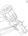
- a Kraftstoffbe colllvoroplasty 1 is shown in a perspective view, which is omitted for ease of clarity on the representation of the filling.
- the Kraftstoffbe colllvortechnik 1 comprises a flow guide 2, in which the outlet pipe of a fuel nozzle, not shown, guided and supported while refueling.
- An attachment 3 is connected to the flow guiding device 2 by means of a latching device 6.
- the locking takes place by clips.
- any other suitable detachable or non-detachable connection can also be provided, for example by means of a bayonet closure or by welding.
- the attachment 3 has a first end A, which is formed substantially cylindrical.
- the first end A of the attachment 3 has a plurality of spacer ribs 5, which is formed by the spacing of the spacer ribs 5 from one another and the spacing of the cylindrical portion of the first end A of the attachment 3 to the flow guide 2 due to the spacer ribs 5.
- the attachment 3 has a second end C, which is also substantially cylindrical. Between the first end A of the attachment 3 and the second end C of the attachment 3 is a taper B which has a substantially frusto-conical lateral surface. The taper B of the attachment 3, together with the columns 4, prevents the fuel from being injected back during refueling and causes an additional suction effect, so that the fuel vapor can mix with the fuel via the gaps 4 and flow into the fuel container.
Landscapes
- Engineering & Computer Science (AREA)
- Mechanical Engineering (AREA)
- Life Sciences & Earth Sciences (AREA)
- Sustainable Development (AREA)
- Sustainable Energy (AREA)
- Chemical & Material Sciences (AREA)
- Combustion & Propulsion (AREA)
- Transportation (AREA)
- Cooling, Air Intake And Gas Exhaust, And Fuel Tank Arrangements In Propulsion Units (AREA)
Abstract
Description
- Die vorliegende Erfindung betrifft eine Kraftstoffbefüllvorrichtung, umfassend einen Befüllleitung, eine in der Befüllleitung angeordnete Strömungsleiteinrichtung, wobei die Strömungsleiteinrichtung so ausgebildet ist, dass während einer Betankung das Auslaufrohr einer Zapfpistole in dieser geführt und abgestützt aufgenommen ist und einen Aufsatz für die Strömungsleiteinrichtung.
- In der
DE102008011733A1 ist eine Kraftstoffbefüllvorrichtung beschrieben, welche ein Lenkrohr aufweist, welche eine laminare Strömung des Kraftstoffs während dem Betanken begünstigen soll, wodurch ein Zurückspritzen des Kraftstoffs auch beim Nachfüllen vermindert werden soll. - Es ist eine Aufgabe der Erfindung, ein alternatives Betankungssystem bereitzustellen mit welchem einerseits das Zurückspritzen von Kraftstoff während dem Betanken einerseits verhindert und die Einhaltung der ORVR (Onboard Refueling Vapor Recovery) Anforderungen andererseits ermöglicht wird.
- Die Lösung der Aufgabe erfolgt durch eine Kraftstoffbefüllvorrichtung mit den Merkmalen gemäß Anspruch 1.
- Erfindungsgemäß ist eine Kraftstoffbefüllvorrichtung, umfassend einen Befüllleitung, eine in der Befüllleitung angeordnete Strömungsleiteinrichtung, wobei die Strömungsleiteinrichtung so ausgebildet ist, dass während einer Betankung das Auslaufrohr einer Zapfpistole in dieser geführt und abgestützt aufgenommen ist und einen Aufsatz für die Strömungsleiteinrichtung, wobei der Aufsatz ein erstes Ende aufweist, welches radial außen an der Strömungsleiteinrichtung angeordnet ist, wobei der Aufsatz ein zweites Ende aufweist, wobei sich der Aufsatz vom ersten Ende zum zweiten Ende hin über eine Verjüngung verjüngt, wobei zwischen dem ersten Ende des Aufsatzes und der Strömungsleiteinrichtung zumindest ein Spalt ausgebildet ist, so dass der während der Betankung in die Kraftstoffbefüllvorrichtung eingeleitete Kraftstoffdampf während einer Betankung durch den zumindest einen Spalt in die Befüllleitung in Richtung eines mit der Befüllleitung verbundenen Kraftstoffbehälters strömen kann.
- Vorteilhaft weist der Aufsatz eine Vielzahl von Spalten zwischen der Strömungsleiteinrichtung und dem Aufsatz auf.
- Der Spalt oder die Spalten bewirken eine Druckentlastung insbesondere beim Nachtanken, da ein im Aufsatz stehender Kraftstoff bzw. Kraftstoffdampf über die Spalten in die Befüllleitung entweichen und bevorzugt über eine Rezirkulierungsleitung in den Kraftstoffbehälter zurückgeleitet werden kann, wodurch eine Beladung eines Aktivkohlefilters (AKF), bei gleichzeitig Einhaltung des gesetzlich vorgeschriebenen ORVR, reduziert werden kann. Aufgrund der Geometrie der Verjüngung des Aufsatzes kann ein Entweichen von Kraftstoff aus der Befüllleitung bzw. der Strömungsleiteinrichtung (das sogenannte "Spitback") verhindert werden.
- Die Rezirkulierungsleitung ist bevorzugt an einem ersten Ende mit einer Hauptentlüftungsleitung verbunden und mit einem zweiten Ende mit der Befüllleitung, wobei das zweite Ende in einem Bereich der Befüllleitung mündet, welcher oberhalb der Spalten angeordnet ist. Die Hauptentlüftungsleitung ist mit dem Kraftstoffbehälter verbunden, wobei Kraftstoffdampf von der Hauptentlüftungsleitung zum AKF und/oder zur Rezirkulierungsleitung strömen kann.
- Während der Betankung entsteht in der Befüllleitung aufgrund der Verjüngung ein Unterdruck wodurch Kraftstoffdampf von der Hauptentlüftungsleitung über die Rezirkulierungsleitung und über die Befüllleitung in den Kraftstoffbehälter zurückgeleitet wird.
- Die Strömungsleiteinrichtung und der mit der Strömungsleiteinrichtung verbundene Aufsatz sind am oberen Ende der Befüllleitung in der Befüllleitung eingesetzt und mit dieser verbunden. Die Befüllleitung, welche in einer bevorzugten Ausführungsform durch Blasformen hergestellt ist, weist am oberen Ende eine Aufweitung auf, in welche die Strömungsleiteinrichtung und der Aufsatz einsetzbar sind, und verjüngt sich bis zum zweiten Ende des Aufsatzes bis die Befüllleitung eine zylindrische Form aufweist, welche bis zum Kraftstoffbehälter im Wesentlichen unverändert bleibt. Durch diese Ausbildung der Befüllleitung wird die Sogwirkung nochmals verstärkt.
- Weiterbildungen der Erfindung sind in den abhängigen Ansprüchen, der Beschreibung sowie den beigefügten Zeichnungen angegeben.
- In einer bevorzugten Ausführungsform bildet das erste Ende des Aufsatzes einen im Wesentlichen zylindrisch ausgebildeten Abschnitt.
- In einer vorteilhaften Ausführungsform ist im ersten Ende des Aufsatzes zumindest eine Distanzrippe angeordnet, wobei sich die Distanzrippe radial nach innen, also in Richtung zur Strömungsleiteinrichtung, erstreckt.
- Im zylindrischen Abschnitt des Aufsatzes sind mehrere Distanzrippen, vorzugsweise regelmäßig zueinander beabstandet, ausgebildet.
- In einer vorteilhaften Ausführungsform werden mehrere Spalte durch die Beabstandung der Distanzrippen zueinander und der Beabstandung des ersten Endes des Aufsatzes zur Strömungsleiteinrichtung aufgrund der Distanzrippen gebildet.
- Aufgrund der Distanzrippen kann der Aufsatz in einer definierten Position zur Strömungsleiteinrichtung positioniert werden.
- Alternativ kann anstatt von Distanzrippen in der Ringfläche des zylindrischen Abschnitts des ersten Endes des Aufsatzes durchgehende Bohrungen in axialer Richtung des zylindrischen Abschnitts vorgesehen werden.
- Der Aufsatz weist zumindest eine Verrastungsgeometrie auf mittels welcher der Aufsatz in eine Gegenverrastungsgeometrie der Strömungsleiteinrichtung verbunden werden kann.
- Vorteilhaft weist der Aufsatz zumindest zwei Verrastungsgeometrien auf. Dadurch wird eine bessere Verbindung zwischen dem Aufsatz und der Strömungsleiteinrichtung erzielt.
- Die Verjüngung des Aufsatzes weist im Wesentlichen die Form einer Kegelstumpfmantelfläche auf.
- Dabei erfüllt die Verjüngung mehrere Funktionen. Einerseits wird durch die Verjüngung erreicht, dass das Zurückspritzen des Kraftstoffs während der Betankung verhindert wird, andererseits bewirkt die Verjüngung, dass die Sogwirkung des Spalts verstärkt wird, wodurch nicht nur die gesetzlichen ORVR Anforderungen leichter erfüllt werden, sondern auch die Beladung des Aktivkohlefilters reduziert wird.
- Das zweite Ende nach der Verjüngung bildet in einer weiteren vorteilhaften Ausführungsform ebenfalls einen zylindrischen Abschnitt.
- Die Strömungsleiteinrichtung ist so ausgebildet, dass das Ende des Auslaufrohres der Zapfpistole nicht über die Strömungsleiteinrichtung ragen kann. Das hat den Vorteil, dass während der Betankung der Treibstoff in den aufgeweiteten Bereich der Verjüngung des Aufsatzes nicht auftreffen kann, sondern erst in dem Bereich des Aufsatzes wo das zweite Ende angeordnet ist. Von dort verteilt sich der Kraftstoff, der zurückspritzen kann, in Richtung der aufgeweiteten Verjüngung und nicht in Richtung der Einlassöffnung der Kraftstoffbefüllvorrichtung. Das erste Ende des Aufsatzes weist dabei bevorzugt eine Länge auf, so dass der zurückspritzende Kraftstoff durch den Spalt, bzw. die Spalte in Richtung des Hohlraums der Befüllleitung und nicht aus der Einlassöffnung der Strömungsleiteinrichtung gelangen kann.
- Die Erfindung wird im Folgenden beispielhaft unter Bezugnahme auf die Zeichnungen beschrieben.
- Fig. 1
- zeigt eine perspektivische Ansicht einer erfindungsgemäßen Kraftstoffbefüllvorrichtung.
- In
Fig. 1 ist eine Kraftstoffbefüllvorrichtung 1 in perspektivischer Ansicht dargestellt, wobei zur einfacheren Übersicht auf die Darstellung der Befüllleitung verzichtet wird. Die Kraftstoffbefüllvorrichtung 1 umfasst eine Strömungsleiteinrichtung 2, in welcher während einer Betankung das Auslaufrohr einer nicht dargestellten Zapfpistole geführt und abgestützt aufgenommen ist. Ein Aufsatz 3 ist mit der Strömungsleiteinrichtung 2 mittels einer Verrastungseinrichtung 6 verbunden. Bevorzugt erfolgt die Verrastung durch Clipsen. Es kann aber auch jede andere geeignete lösbare oder unlösbare Verbindung vorgesehen werden, beispielsweise mittels Bajonettverschluss oder durch Verschweißen. Der Aufsatz 3 weist ein erstes Ende A auf, welches im Wesentlichen zylindrisch ausgebildet ist. Das erste Ende A des Aufsatzes 3 weist mehrere Distanzrippen 5 auf welche, durch die Beabstandung der Distanzrippen 5 zueinander und der Beabstandung des zylindrischen Abschnitts des ersten Endes A des Aufsatzes 3 zur Strömungsleiteinrichtung 2 aufgrund der Distanzrippen 5 gebildet wird. Der Aufsatz 3 weist ein zweites Ende C auf, welches ebenfalls im Wesentlichen zylindrisch ausgebildet ist. Zwischen dem ersten Ende A des Aufsatzes 3 und dem zweiten Ende C des Aufsatzes 3 befindet sich eine Verjüngung B welche eine im Wesentlichen kegelstumpfförmige Mantelfläche aufweist. Die Verjüngung B des Aufsatzes 3 bewirkt zusammen mit den Spalten 4, dass ein Zurückspritzen des Kraftstoffs während dem Betanken verhindert wird und bewirkt einen zusätzlichen Saugeffekt, so dass der Kraftstoffdampf über die Spalte 4 mit dem Kraftstoff vermengt und in den Kraftstoffbehälter strömen kann.
Claims (9)
- Kraftstoffbefüllvorrichtung (1), umfassend einen Befüllleitung, eine in der Befüllleitung angeordnete Strömungsleiteinrichtung (2), wobei die Strömungsleiteinrichtung (2) so ausgebildet ist, dass während einer Betankung das Auslaufrohr einer Zapfpistole in dieser geführt und abgestützt aufgenommen ist und einen Aufsatz (3) für die Strömungsleiteinrichtung (2),
dadurch gekennzeichnet, dass der Aufsatz (3) ein erstes Ende (A) aufweist, welches radial außen an der Strömungsleiteinrichtung (2) angeordnet ist, wobei der Aufsatz (3) ein zweites Ende (C) aufweist, wobei sich der Aufsatz (3) vom ersten Ende (A) zum zweiten Ende (C) hin über eine Verjüngung (B) verjüngt, wobei zwischen dem ersten Ende (A) des Aufsatzes (3) und der Strömungsleiteinrichtung (2) zumindest ein Spalt (4) ausgebildet ist, so dass der während der Betankung in die Kraftstoffbefüllvorrichtung (1) eingeleitete Kraftstoffdampf während einer Betankung durch den zumindest einen Spalt (4) in die Befüllleitung in Richtung eines mit der Befüllleitung verbundenen Kraftstoffbehälters strömen kann. - Kraftstoffbefüllvorrichtung (1) nach Anspruch 1,
dadurch gekennzeichnet, dass das erste Ende (A) des Aufsatzes (3) einen im Wesentlichen zylindrisch ausgebildeten Abschnitt bildet. - Kraftstoffbefüllvorrichtung (1) nach Anspruch 1 oder 2,
dadurch gekennzeichnet, dass im ersten Ende (A) des Aufsatzes (3) zumindest eine Distanzrippe (5) angeordnet ist, wobei sich die Distanzrippe (5) radial nach innen, also in Richtung zur Strömungsleiteinrichtung (2), erstreckt. - Kraftstoffbefüllvorrichtung (1) Anspruch 3,
dadurch gekennzeichnet, dass im zylindrischen Abschnitt des Aufsatzes (3) mehrere Distanzrippen (5), vorzugsweise regelmäßig zueinander beabstandet, ausgebildet sind. - Kraftstoffbefüllvorrichtung (1) nach zumindest einem der vorhergehenden Ansprüche,
dadurch gekennzeichnet, dass mehrere Spalte (4) durch die Beabstandung der Distanzrippen (5) zueinander und der Beabstandung des ersten Endes (A) des Aufsatzes (3) zur Strömungsleiteinrichtung (2) aufgrund der Distanzrippen (5) gebildet werden. - Kraftstoffbefüllvorrichtung (1) nach zumindest einem der vorhergehenden Ansprüche,
dadurch gekennzeichnet, dass der Aufsatz (3) mittels einer Verrastungseinrichtung (6) mit der Strömungsleiteinrichtung (2) verbunden ist. - Kraftstoffbefüllvorrichtung (1) nach zumindest einem der vorhergehenden Ansprüche,
dadurch gekennzeichnet, dass die Verjüngung (B) des Aufsatzes (3) im Wesentlichen die Form einer Kegelstumpfmantelfläche aufweist. - Kraftstoffbefüllvorrichtung (1) nach zumindest einem der vorhergehenden Ansprüche,
dadurch gekennzeichnet, dass das zweite Ende (C) nach der Verjüngung (B) einen zylindrischen Abschnitt bildet. - Kraftstoffbefüllvorrichtung (1) nach zumindest einem der vorhergehenden Ansprüche,
dadurch gekennzeichnet, dass die Strömungsleiteinrichtung (2) so ausgebildet ist, dass das Ende des Auslaufrohres der Zapfpistole nicht über die Strömungsleiteinrichtung (2) ragen kann.
Priority Applications (3)
| Application Number | Priority Date | Filing Date | Title |
|---|---|---|---|
| EP18159688.3A EP3533650B1 (de) | 2018-03-02 | 2018-03-02 | Kraftstoffbefüllvorrichtung |
| US16/207,364 US10807856B2 (en) | 2018-03-02 | 2018-12-03 | Fuel filling device |
| CN201811509526.7A CN110217100B (zh) | 2018-03-02 | 2018-12-11 | 燃料加注装置 |
Applications Claiming Priority (1)
| Application Number | Priority Date | Filing Date | Title |
|---|---|---|---|
| EP18159688.3A EP3533650B1 (de) | 2018-03-02 | 2018-03-02 | Kraftstoffbefüllvorrichtung |
Publications (2)
| Publication Number | Publication Date |
|---|---|
| EP3533650A1 true EP3533650A1 (de) | 2019-09-04 |
| EP3533650B1 EP3533650B1 (de) | 2020-06-24 |
Family
ID=61563187
Family Applications (1)
| Application Number | Title | Priority Date | Filing Date |
|---|---|---|---|
| EP18159688.3A Active EP3533650B1 (de) | 2018-03-02 | 2018-03-02 | Kraftstoffbefüllvorrichtung |
Country Status (3)
| Country | Link |
|---|---|
| US (1) | US10807856B2 (de) |
| EP (1) | EP3533650B1 (de) |
| CN (1) | CN110217100B (de) |
Citations (4)
| Publication number | Priority date | Publication date | Assignee | Title |
|---|---|---|---|---|
| DE19948312A1 (de) * | 1999-10-07 | 2001-04-12 | Daimler Chrysler Ag | Einfüllstutzen für einen Kraftstofftank |
| DE102008011733A1 (de) | 2008-02-28 | 2009-09-03 | GM Global Technology Operations, Inc., Detroit | Kraftstoffbefüllvorrichtung |
| JP2015143043A (ja) * | 2014-01-31 | 2015-08-06 | 株式会社Fts | フィラーパイプ |
| DE102015214084A1 (de) * | 2015-07-24 | 2016-08-18 | Allgaier Werke Gmbh | Einfüllstutzen für einen Kraftstoffbehälter eines Kraftfahrzeuges |
Family Cites Families (4)
| Publication number | Priority date | Publication date | Assignee | Title |
|---|---|---|---|---|
| JP3578421B2 (ja) * | 1995-03-03 | 2004-10-20 | 本田技研工業株式会社 | 燃料タンクにおける給油管構造 |
| DE602006004708D1 (de) * | 2006-05-01 | 2009-02-26 | Ford Global Tech Llc | Kraftstoff-Einfüllstutzen für ein Kraftfahrzeug |
| US7997307B2 (en) * | 2007-10-30 | 2011-08-16 | Eaton Corporation | Fill nozzle positioning apparatus |
| US10029560B2 (en) * | 2015-03-19 | 2018-07-24 | Toyoda Gosei Co., Ltd. | Fuel supply apparatus |
-
2018
- 2018-03-02 EP EP18159688.3A patent/EP3533650B1/de active Active
- 2018-12-03 US US16/207,364 patent/US10807856B2/en active Active
- 2018-12-11 CN CN201811509526.7A patent/CN110217100B/zh active Active
Patent Citations (4)
| Publication number | Priority date | Publication date | Assignee | Title |
|---|---|---|---|---|
| DE19948312A1 (de) * | 1999-10-07 | 2001-04-12 | Daimler Chrysler Ag | Einfüllstutzen für einen Kraftstofftank |
| DE102008011733A1 (de) | 2008-02-28 | 2009-09-03 | GM Global Technology Operations, Inc., Detroit | Kraftstoffbefüllvorrichtung |
| JP2015143043A (ja) * | 2014-01-31 | 2015-08-06 | 株式会社Fts | フィラーパイプ |
| DE102015214084A1 (de) * | 2015-07-24 | 2016-08-18 | Allgaier Werke Gmbh | Einfüllstutzen für einen Kraftstoffbehälter eines Kraftfahrzeuges |
Also Published As
| Publication number | Publication date |
|---|---|
| US20190270634A1 (en) | 2019-09-05 |
| CN110217100A (zh) | 2019-09-10 |
| EP3533650B1 (de) | 2020-06-24 |
| US10807856B2 (en) | 2020-10-20 |
| CN110217100B (zh) | 2022-05-17 |
Similar Documents
| Publication | Publication Date | Title |
|---|---|---|
| DE69819125T2 (de) | Unwechselbare Verbindungsanordnung | |
| DE102011014818B4 (de) | Innentankfilter für ein brennstoffpumpenmodul | |
| DE2440986A1 (de) | Tuelle fuer einfuellstutzen eines behaelters | |
| EP3025893B1 (de) | Vorrichtung zum schutz vor fehlbetankung | |
| EP2789490A1 (de) | Befüllkopf für einen Flüssigkeitstank | |
| EP1004777B1 (de) | Saugstrahlpumpe | |
| DE2430253A1 (de) | Kraftstoffeinfuellhahn und kraftstoffeinfuellstutzen | |
| EP3055156B1 (de) | Einfüllstutzen für einen kraftfahrzeug-betriebsflüssigkeitsbehälter | |
| WO2016087064A1 (de) | Kraftstoffpumpe mit verbessertem förderverhalten | |
| EP3498359A1 (de) | Filterelement und zugehörige filtereinrichtung | |
| EP1842712A2 (de) | Vorrichtung zum Verhindern des Ausspritzens von Kraftstoff aus einem Kraftstofftank bei offenem Tankstutzen | |
| EP3533650A1 (de) | Kraftstoffbefüllvorrichtung | |
| EP3159531B1 (de) | Düsenbaugruppe für ein brennstoffeinspritzventil zum einspritzen eines gasförmigen und/oder flüssigen brennstoffs, brennstoffeinspritzventil | |
| EP3118041B1 (de) | Verbesserte strömungsleiteinrichtung für einen tankeinfüllstutzen | |
| DE2211451A1 (de) | Vorrichtung zur drehbaren verbindung zweier konzentrischer bauteile | |
| WO2007066296A1 (de) | Bauelement zur einfüllsicherung für den einsatz im betankungsstutzen von dieselfahrzeugen | |
| DE2930499C2 (de) | ||
| EP3159530B1 (de) | Düsenbaugruppe für ein brennstoffeinspritzventil zum einspritzen eines gasförmigen und/oder flüssigen brennstoffs, brennstoffeinspritzventil | |
| WO2017207343A1 (de) | Betankungsarmatur zur betankung eines kraftfahrzeugs mit einem gasförmigen kraftstoff | |
| EP3418097B1 (de) | Befüllkopf für einen flüssigkeitstank | |
| DE10232309B4 (de) | Einfülleinrichtung, insbesondere Öleinfülleinrichtung an einer Brennkraftmaschine | |
| DE102012104849A1 (de) | Kraftstoffbefüllvorrichtung und Kraftfahrzeug | |
| EP3138717A1 (de) | Einfüllkopf | |
| EP4041585B1 (de) | Tankstutzenverschluss für einen kraftstofftank | |
| EP0623771A2 (de) | Unterbrechungsventil |
Legal Events
| Date | Code | Title | Description |
|---|---|---|---|
| PUAI | Public reference made under article 153(3) epc to a published international application that has entered the european phase |
Free format text: ORIGINAL CODE: 0009012 |
|
| STAA | Information on the status of an ep patent application or granted ep patent |
Free format text: STATUS: REQUEST FOR EXAMINATION WAS MADE |
|
| 17P | Request for examination filed |
Effective date: 20181015 |
|
| AK | Designated contracting states |
Kind code of ref document: A1 Designated state(s): AL AT BE BG CH CY CZ DE DK EE ES FI FR GB GR HR HU IE IS IT LI LT LU LV MC MK MT NL NO PL PT RO RS SE SI SK SM TR |
|
| AX | Request for extension of the european patent |
Extension state: BA ME |
|
| RIC1 | Information provided on ipc code assigned before grant |
Ipc: B60K 15/04 20060101AFI20191219BHEP Ipc: B60K 15/03 20060101ALN20191219BHEP |
|
| GRAP | Despatch of communication of intention to grant a patent |
Free format text: ORIGINAL CODE: EPIDOSNIGR1 |
|
| STAA | Information on the status of an ep patent application or granted ep patent |
Free format text: STATUS: GRANT OF PATENT IS INTENDED |
|
| RIC1 | Information provided on ipc code assigned before grant |
Ipc: B60K 15/03 20060101ALN20200110BHEP Ipc: B60K 15/04 20060101AFI20200110BHEP |
|
| RIC1 | Information provided on ipc code assigned before grant |
Ipc: B60K 15/04 20060101AFI20200131BHEP Ipc: B60K 15/03 20060101ALN20200131BHEP |
|
| INTG | Intention to grant announced |
Effective date: 20200217 |
|
| RIC1 | Information provided on ipc code assigned before grant |
Ipc: B60K 15/03 20060101ALN20200207BHEP Ipc: B60K 15/04 20060101AFI20200207BHEP |
|
| GRAS | Grant fee paid |
Free format text: ORIGINAL CODE: EPIDOSNIGR3 |
|
| GRAA | (expected) grant |
Free format text: ORIGINAL CODE: 0009210 |
|
| STAA | Information on the status of an ep patent application or granted ep patent |
Free format text: STATUS: THE PATENT HAS BEEN GRANTED |
|
| AK | Designated contracting states |
Kind code of ref document: B1 Designated state(s): AL AT BE BG CH CY CZ DE DK EE ES FI FR GB GR HR HU IE IS IT LI LT LU LV MC MK MT NL NO PL PT RO RS SE SI SK SM TR |
|
| REG | Reference to a national code |
Ref country code: GB Ref legal event code: FG4D Free format text: NOT ENGLISH |
|
| REG | Reference to a national code |
Ref country code: CH Ref legal event code: EP |
|
| REG | Reference to a national code |
Ref country code: AT Ref legal event code: REF Ref document number: 1283545 Country of ref document: AT Kind code of ref document: T Effective date: 20200715 |
|
| REG | Reference to a national code |
Ref country code: DE Ref legal event code: R096 Ref document number: 502018001714 Country of ref document: DE |
|
| REG | Reference to a national code |
Ref country code: IE Ref legal event code: FG4D Free format text: LANGUAGE OF EP DOCUMENT: GERMAN |
|
| PG25 | Lapsed in a contracting state [announced via postgrant information from national office to epo] |
Ref country code: SE Free format text: LAPSE BECAUSE OF FAILURE TO SUBMIT A TRANSLATION OF THE DESCRIPTION OR TO PAY THE FEE WITHIN THE PRESCRIBED TIME-LIMIT Effective date: 20200624 Ref country code: GR Free format text: LAPSE BECAUSE OF FAILURE TO SUBMIT A TRANSLATION OF THE DESCRIPTION OR TO PAY THE FEE WITHIN THE PRESCRIBED TIME-LIMIT Effective date: 20200925 Ref country code: NO Free format text: LAPSE BECAUSE OF FAILURE TO SUBMIT A TRANSLATION OF THE DESCRIPTION OR TO PAY THE FEE WITHIN THE PRESCRIBED TIME-LIMIT Effective date: 20200924 Ref country code: LT Free format text: LAPSE BECAUSE OF FAILURE TO SUBMIT A TRANSLATION OF THE DESCRIPTION OR TO PAY THE FEE WITHIN THE PRESCRIBED TIME-LIMIT Effective date: 20200624 Ref country code: FI Free format text: LAPSE BECAUSE OF FAILURE TO SUBMIT A TRANSLATION OF THE DESCRIPTION OR TO PAY THE FEE WITHIN THE PRESCRIBED TIME-LIMIT Effective date: 20200624 |
|
| REG | Reference to a national code |
Ref country code: LT Ref legal event code: MG4D |
|
| PG25 | Lapsed in a contracting state [announced via postgrant information from national office to epo] |
Ref country code: LV Free format text: LAPSE BECAUSE OF FAILURE TO SUBMIT A TRANSLATION OF THE DESCRIPTION OR TO PAY THE FEE WITHIN THE PRESCRIBED TIME-LIMIT Effective date: 20200624 Ref country code: HR Free format text: LAPSE BECAUSE OF FAILURE TO SUBMIT A TRANSLATION OF THE DESCRIPTION OR TO PAY THE FEE WITHIN THE PRESCRIBED TIME-LIMIT Effective date: 20200624 Ref country code: RS Free format text: LAPSE BECAUSE OF FAILURE TO SUBMIT A TRANSLATION OF THE DESCRIPTION OR TO PAY THE FEE WITHIN THE PRESCRIBED TIME-LIMIT Effective date: 20200624 Ref country code: BG Free format text: LAPSE BECAUSE OF FAILURE TO SUBMIT A TRANSLATION OF THE DESCRIPTION OR TO PAY THE FEE WITHIN THE PRESCRIBED TIME-LIMIT Effective date: 20200924 |
|
| REG | Reference to a national code |
Ref country code: NL Ref legal event code: MP Effective date: 20200624 |
|
| PG25 | Lapsed in a contracting state [announced via postgrant information from national office to epo] |
Ref country code: NL Free format text: LAPSE BECAUSE OF FAILURE TO SUBMIT A TRANSLATION OF THE DESCRIPTION OR TO PAY THE FEE WITHIN THE PRESCRIBED TIME-LIMIT Effective date: 20200624 Ref country code: AL Free format text: LAPSE BECAUSE OF FAILURE TO SUBMIT A TRANSLATION OF THE DESCRIPTION OR TO PAY THE FEE WITHIN THE PRESCRIBED TIME-LIMIT Effective date: 20200624 |
|
| PG25 | Lapsed in a contracting state [announced via postgrant information from national office to epo] |
Ref country code: SM Free format text: LAPSE BECAUSE OF FAILURE TO SUBMIT A TRANSLATION OF THE DESCRIPTION OR TO PAY THE FEE WITHIN THE PRESCRIBED TIME-LIMIT Effective date: 20200624 Ref country code: PT Free format text: LAPSE BECAUSE OF FAILURE TO SUBMIT A TRANSLATION OF THE DESCRIPTION OR TO PAY THE FEE WITHIN THE PRESCRIBED TIME-LIMIT Effective date: 20201026 Ref country code: CZ Free format text: LAPSE BECAUSE OF FAILURE TO SUBMIT A TRANSLATION OF THE DESCRIPTION OR TO PAY THE FEE WITHIN THE PRESCRIBED TIME-LIMIT Effective date: 20200624 Ref country code: ES Free format text: LAPSE BECAUSE OF FAILURE TO SUBMIT A TRANSLATION OF THE DESCRIPTION OR TO PAY THE FEE WITHIN THE PRESCRIBED TIME-LIMIT Effective date: 20200624 Ref country code: IT Free format text: LAPSE BECAUSE OF FAILURE TO SUBMIT A TRANSLATION OF THE DESCRIPTION OR TO PAY THE FEE WITHIN THE PRESCRIBED TIME-LIMIT Effective date: 20200624 Ref country code: RO Free format text: LAPSE BECAUSE OF FAILURE TO SUBMIT A TRANSLATION OF THE DESCRIPTION OR TO PAY THE FEE WITHIN THE PRESCRIBED TIME-LIMIT Effective date: 20200624 Ref country code: EE Free format text: LAPSE BECAUSE OF FAILURE TO SUBMIT A TRANSLATION OF THE DESCRIPTION OR TO PAY THE FEE WITHIN THE PRESCRIBED TIME-LIMIT Effective date: 20200624 |
|
| REG | Reference to a national code |
Ref country code: DE Ref legal event code: R082 Ref document number: 502018001714 Country of ref document: DE Representative=s name: RAUSCH, GABRIELE, DIPL.-PHYS. DR.RER.NAT., DE Ref country code: DE Ref legal event code: R081 Ref document number: 502018001714 Country of ref document: DE Owner name: MAGNA ENERGY STORAGE SYSTEMS GESMBH, AT Free format text: FORMER OWNER: MAGNA STEYR FUEL SYSTEMS GESMBH, 8261 SINABELKIRCHEN, AT |
|
| PG25 | Lapsed in a contracting state [announced via postgrant information from national office to epo] |
Ref country code: PL Free format text: LAPSE BECAUSE OF FAILURE TO SUBMIT A TRANSLATION OF THE DESCRIPTION OR TO PAY THE FEE WITHIN THE PRESCRIBED TIME-LIMIT Effective date: 20200624 Ref country code: SK Free format text: LAPSE BECAUSE OF FAILURE TO SUBMIT A TRANSLATION OF THE DESCRIPTION OR TO PAY THE FEE WITHIN THE PRESCRIBED TIME-LIMIT Effective date: 20200624 Ref country code: IS Free format text: LAPSE BECAUSE OF FAILURE TO SUBMIT A TRANSLATION OF THE DESCRIPTION OR TO PAY THE FEE WITHIN THE PRESCRIBED TIME-LIMIT Effective date: 20201024 |
|
| REG | Reference to a national code |
Ref country code: DE Ref legal event code: R097 Ref document number: 502018001714 Country of ref document: DE |
|
| PG25 | Lapsed in a contracting state [announced via postgrant information from national office to epo] |
Ref country code: DK Free format text: LAPSE BECAUSE OF FAILURE TO SUBMIT A TRANSLATION OF THE DESCRIPTION OR TO PAY THE FEE WITHIN THE PRESCRIBED TIME-LIMIT Effective date: 20200624 |
|
| PLBE | No opposition filed within time limit |
Free format text: ORIGINAL CODE: 0009261 |
|
| STAA | Information on the status of an ep patent application or granted ep patent |
Free format text: STATUS: NO OPPOSITION FILED WITHIN TIME LIMIT |
|
| 26N | No opposition filed |
Effective date: 20210325 |
|
| PG25 | Lapsed in a contracting state [announced via postgrant information from national office to epo] |
Ref country code: SI Free format text: LAPSE BECAUSE OF FAILURE TO SUBMIT A TRANSLATION OF THE DESCRIPTION OR TO PAY THE FEE WITHIN THE PRESCRIBED TIME-LIMIT Effective date: 20200624 |
|
| PG25 | Lapsed in a contracting state [announced via postgrant information from national office to epo] |
Ref country code: MC Free format text: LAPSE BECAUSE OF FAILURE TO SUBMIT A TRANSLATION OF THE DESCRIPTION OR TO PAY THE FEE WITHIN THE PRESCRIBED TIME-LIMIT Effective date: 20200624 |
|
| REG | Reference to a national code |
Ref country code: CH Ref legal event code: PL |
|
| REG | Reference to a national code |
Ref country code: BE Ref legal event code: MM Effective date: 20210331 |
|
| PG25 | Lapsed in a contracting state [announced via postgrant information from national office to epo] |
Ref country code: IE Free format text: LAPSE BECAUSE OF NON-PAYMENT OF DUE FEES Effective date: 20210302 Ref country code: LI Free format text: LAPSE BECAUSE OF NON-PAYMENT OF DUE FEES Effective date: 20210331 Ref country code: LU Free format text: LAPSE BECAUSE OF NON-PAYMENT OF DUE FEES Effective date: 20210302 Ref country code: CH Free format text: LAPSE BECAUSE OF NON-PAYMENT OF DUE FEES Effective date: 20210331 |
|
| PG25 | Lapsed in a contracting state [announced via postgrant information from national office to epo] |
Ref country code: BE Free format text: LAPSE BECAUSE OF NON-PAYMENT OF DUE FEES Effective date: 20210331 |
|
| PG25 | Lapsed in a contracting state [announced via postgrant information from national office to epo] |
Ref country code: CY Free format text: LAPSE BECAUSE OF FAILURE TO SUBMIT A TRANSLATION OF THE DESCRIPTION OR TO PAY THE FEE WITHIN THE PRESCRIBED TIME-LIMIT Effective date: 20200624 |
|
| PG25 | Lapsed in a contracting state [announced via postgrant information from national office to epo] |
Ref country code: HU Free format text: LAPSE BECAUSE OF FAILURE TO SUBMIT A TRANSLATION OF THE DESCRIPTION OR TO PAY THE FEE WITHIN THE PRESCRIBED TIME-LIMIT; INVALID AB INITIO Effective date: 20180302 |
|
| PG25 | Lapsed in a contracting state [announced via postgrant information from national office to epo] |
Ref country code: MK Free format text: LAPSE BECAUSE OF FAILURE TO SUBMIT A TRANSLATION OF THE DESCRIPTION OR TO PAY THE FEE WITHIN THE PRESCRIBED TIME-LIMIT Effective date: 20200624 |
|
| REG | Reference to a national code |
Ref country code: AT Ref legal event code: MM01 Ref document number: 1283545 Country of ref document: AT Kind code of ref document: T Effective date: 20230302 |
|
| PG25 | Lapsed in a contracting state [announced via postgrant information from national office to epo] |
Ref country code: AT Free format text: LAPSE BECAUSE OF NON-PAYMENT OF DUE FEES Effective date: 20230302 |
|
| PG25 | Lapsed in a contracting state [announced via postgrant information from national office to epo] |
Ref country code: AT Free format text: LAPSE BECAUSE OF NON-PAYMENT OF DUE FEES Effective date: 20230302 |
|
| PG25 | Lapsed in a contracting state [announced via postgrant information from national office to epo] |
Ref country code: MT Free format text: LAPSE BECAUSE OF FAILURE TO SUBMIT A TRANSLATION OF THE DESCRIPTION OR TO PAY THE FEE WITHIN THE PRESCRIBED TIME-LIMIT Effective date: 20200624 |
|
| REG | Reference to a national code |
Ref country code: DE Ref legal event code: R082 Ref document number: 502018001714 Country of ref document: DE Representative=s name: EULER, MATTHIAS, DR., DE |
|
| PG25 | Lapsed in a contracting state [announced via postgrant information from national office to epo] |
Ref country code: TR Free format text: LAPSE BECAUSE OF FAILURE TO SUBMIT A TRANSLATION OF THE DESCRIPTION OR TO PAY THE FEE WITHIN THE PRESCRIBED TIME-LIMIT Effective date: 20200624 |
|
| PGFP | Annual fee paid to national office [announced via postgrant information from national office to epo] |
Ref country code: GB Payment date: 20260324 Year of fee payment: 9 |
|
| PGFP | Annual fee paid to national office [announced via postgrant information from national office to epo] |
Ref country code: DE Payment date: 20260319 Year of fee payment: 9 |
|
| PGFP | Annual fee paid to national office [announced via postgrant information from national office to epo] |
Ref country code: AT Payment date: 20260410 Year of fee payment: 5 |
|
| PGFP | Annual fee paid to national office [announced via postgrant information from national office to epo] |
Ref country code: FR Payment date: 20260320 Year of fee payment: 9 |