EP3533547A1 - Micro-teeth arrangement designable end mill having tip blade for dedicated use with carbon fiber composite material - Google Patents
Micro-teeth arrangement designable end mill having tip blade for dedicated use with carbon fiber composite material Download PDFInfo
- Publication number
- EP3533547A1 EP3533547A1 EP18854324.3A EP18854324A EP3533547A1 EP 3533547 A1 EP3533547 A1 EP 3533547A1 EP 18854324 A EP18854324 A EP 18854324A EP 3533547 A1 EP3533547 A1 EP 3533547A1
- Authority
- EP
- European Patent Office
- Prior art keywords
- cutting edge
- micro
- tooth
- cutter
- end cutting
- Prior art date
- Legal status (The legal status is an assumption and is not a legal conclusion. Google has not performed a legal analysis and makes no representation as to the accuracy of the status listed.)
- Granted
Links
Images


Classifications
-
- B—PERFORMING OPERATIONS; TRANSPORTING
- B23—MACHINE TOOLS; METAL-WORKING NOT OTHERWISE PROVIDED FOR
- B23C—MILLING
- B23C5/00—Milling-cutters
- B23C5/16—Milling-cutters characterised by physical features other than shape
- B23C5/18—Milling-cutters characterised by physical features other than shape with permanently-fixed cutter-bits or teeth
-
- B—PERFORMING OPERATIONS; TRANSPORTING
- B23—MACHINE TOOLS; METAL-WORKING NOT OTHERWISE PROVIDED FOR
- B23C—MILLING
- B23C5/00—Milling-cutters
- B23C5/02—Milling-cutters characterised by the shape of the cutter
- B23C5/10—Shank-type cutters, i.e. with an integral shaft
-
- B—PERFORMING OPERATIONS; TRANSPORTING
- B23—MACHINE TOOLS; METAL-WORKING NOT OTHERWISE PROVIDED FOR
- B23C—MILLING
- B23C5/00—Milling-cutters
- B23C5/16—Milling-cutters characterised by physical features other than shape
- B23C5/165—Milling-cutters characterised by physical features other than shape with chipbreaking or chipdividing equipment
-
- B—PERFORMING OPERATIONS; TRANSPORTING
- B23—MACHINE TOOLS; METAL-WORKING NOT OTHERWISE PROVIDED FOR
- B23C—MILLING
- B23C2210/00—Details of milling cutters
- B23C2210/04—Angles
- B23C2210/0485—Helix angles
-
- B—PERFORMING OPERATIONS; TRANSPORTING
- B23—MACHINE TOOLS; METAL-WORKING NOT OTHERWISE PROVIDED FOR
- B23C—MILLING
- B23C2210/00—Details of milling cutters
- B23C2210/04—Angles
- B23C2210/0485—Helix angles
- B23C2210/0492—Helix angles different
-
- B—PERFORMING OPERATIONS; TRANSPORTING
- B23—MACHINE TOOLS; METAL-WORKING NOT OTHERWISE PROVIDED FOR
- B23C—MILLING
- B23C2210/00—Details of milling cutters
- B23C2210/28—Arrangement of teeth
-
- B—PERFORMING OPERATIONS; TRANSPORTING
- B23—MACHINE TOOLS; METAL-WORKING NOT OTHERWISE PROVIDED FOR
- B23C—MILLING
- B23C2210/00—Details of milling cutters
- B23C2210/32—Details of teeth
- B23C2210/326—File like cutting teeth, e.g. the teeth of cutting burrs
-
- B—PERFORMING OPERATIONS; TRANSPORTING
- B23—MACHINE TOOLS; METAL-WORKING NOT OTHERWISE PROVIDED FOR
- B23C—MILLING
- B23C2226/00—Materials of tools or workpieces not comprising a metal
- B23C2226/27—Composites, e.g. fibre reinforced composites
Definitions
- the present invention belongs to the technical field of milling tools in machining, and relates to a special end cutting edge attached cutter for carbon fiber reinforced polymer/plastic (CFRP) with designable micro-tooth configuration.
- CFRP carbon fiber reinforced polymer/plastic
- Two parallel V-shaped chip pockets are designed on the end cutting edge of the cutter in two cutting edge directions which are symmetrical around a cutter axis as a center.
- the structure may enhance chip removal performance during high-speed milling of impenetrable slots and impenetrable windows, reduce wear of the end cutting edge, conduct configuration design for micro-teeth of the peripheral cutting edge, reduce the cutting thickness of the micro-tooth cutting edges, effectively solve the problem of damage of the micro-tooth edges and finally enhance the surface quality of window bottoms and slot bottoms and the service life of the cutter.
- CFRP Carbon fiber reinforced polymer/plastic
- the CFRP belongs to typical difficult-to-machine material wherein reinforced fibers and resin matrix have different linear expansion coefficients.
- the reinforced fibers are extremely easy to generate brittle fracture.
- the cutting edge continuously bears the loads of the matrix and the fibers. The loads are centralized on a small area near a cutting contact point.
- micro-teeth are staggered in a certain rule. Micro-tooth configuration can determine overlaps of two adjacent micro-teeth.
- the cutting thickness of the edge part of the micro-teeth is larger than the cutting thickness of the middle parts of the micro-teeth, resulting in a large cutting force on the edge part.
- the edge part is more prone to damage.
- the cutting edges are overlapped and the middle parts of the micro-teeth are not overlapped, the cutting thickness of the micro-tooth edge can be reduced, thereby effectively protecting the edge of micro-tooth.
- a "carbide fish-scale type milling cutter” with patent application number of 200910013142.0 invented by Tang Chensheng et al. relates to a milling cutter for milling processing of composite materials such as carbon fibers and glass fibers.
- a left-hand flute and a right-hand flute are symmetrically staggered to form a cutting unit.
- the number of the cutting edges is increased to 24, which is equivalent, to a certain degree, to that the milling cutters with double edges and four edges improve cutting efficiency and processing quality and reduce the milling force.
- the traditional milling cutters mentioned in the above patents only have chip pockets between cutting edges in the end cutting edge, and are not designed with chip pockets at the end cutting edge axis.
- the chips at the end cutting edge axis of the milling cutter are difficult to be removed due to small centrifugal force, and are extremely easy to concentrate on the end cutting edge axis and constantly wear the cutting edges, resulting in difficulty to ensure the processing quality of the bottom surface due to fast wear of the cutting edges. Therefore, the traditional milling cutters have certain limitations in the practical application of impenetrable slot and impenetrable window milling. Furthermore, the design of the micro-tooth milling cutters in the above invention patents does not consider the influence of micro-tooth configuration on damage of the cutting edges. If micro-tooth configuration is unreasonable, the micro-tooth edges will be easy to damage, thereby reducing the processing quality and the cutter life.
- the present invention relates to a special end cutting edge attached cutter for carbon fiber reinforced polymer/plastic (CFRP) with designable micro-tooth configuration.
- Two parallel V-shaped chip pockets are designed on an end cutting edge of the cutter in two cutting edge directions which are symmetrical around a cutter axis as a center so as to solve the problem of chip aggregation caused by small centrifugal force at the end cutting edge axis of the traditional milling cutter when milling impenetrable slots and impenetrable windows; and special micro-tooth configuration design is considered for the peripheral cutting edge of the milling cutter so as to solve the problems of poor chip removal and heat dissipation at the end cutting edge, serious wear and corner chipping at the weak edge of the peripheral cutting edge of the micro-teeth when milling impenetrable slots and impenetrable windows at high speed by the CFRP, thereby enhancing the service life and the cutting performance of the cutter.
- CFRP carbon fiber reinforced polymer/plastic
- the technical solution of the present invention is: To solve the problems of difficult chip removal and rapid wear of the end cutting edge, two parallel V-shaped chip pockets are designed on the end cutting edge of the cutter in two cutting edge directions which are symmetrical around a cutter axis as a center.
- the V-shaped chip pocket is connected and communicated with the chip pocket of the end cutting edge, so that the chips at the end cutting edge axis can be quickly and effectively removed when milling impenetrable slots and impenetrable windows at high speed and friction heat between the end cutting edge and the material is quickly radiated, to achieve the purpose of reducing wear of the end cutting edge.
- a special end cutting edge attached cutter for CFRP with designable micro-tooth configuration comprises an end cutting edge I, a peripheral cutting edge II with variation inverse helical groove, a peripheral cutting edge III with constant inverse helical groove and a shank IV, wherein the end cutting edge I is designed with a rake face 2 of end cutting edge, a flank face 3 of end cutting edge, and a secondary flank face 4 of end cutting edge, and also has a chip pocket 5 of end cutting edge; and a primary cutting edge has a rake angle of 0°, a primary relief angle ⁇ f1 of 7° and a secondary relief angle ⁇ f2 of 14°.
- Parallel V-shaped chip pockets 1 are designed on the end cutting edge I in two cutting edge directions which are symmetrical around a cutter axis as a center, and the V-shaped chip pocket 1 presents such a structural shape that a bottom is narrow and a top is wide, which is beneficial for quickly removing the chips of powdery CFRP.
- the peripheral cutting edge II with variation inverse helical groove is of an asymmetric-and spiral-stagger structure, and m right-hand flutes 7 and n left-hand flutes 8 are staggered to form a plurality of equidimensional micro-teeth 6; to reduce the vibration of the end cutting edge I and a transition part of peripheral cutting edge during slot milling, a section of peripheral cutting edge II with variation left-hand inverse 8 helical flute angle is designed near the end cutting edge I; the peripheral cutting edge points to the end cutting edge direction and the change relationship of the helical angle of the left-hand flutes 8 is ⁇ 1 ⁇ 2 ⁇ 3 .
- micro-tooth configuration of the peripheral cutting edge of the cutter is invented.
- the overlapping configuration mode of two micro-tooth edges can effectively reduce cutting thickness at the edges, thereby avoiding the phenomenon of easy corner chipping at the weak edges and realizing high-speed, steady and effective processing of the CFRP under large cutting amount.
- a three-dimensional stereographic cutter is sectioned along an axial direction and then is unfolded; the peripheral cutting edge III with constant inverse helical groove that represents the configuration mode is selected to form a two-dimensional schematic diagram of micro-tooth configuration of the cutter by using a tangential direction and an axial direction to form a coordinate system; the right-hand flutes 7 and the left-hand flutes 8 are staggered to form micro-teeth 6; the micro-teeth 6 comprise a lower cutting edge 9 and an upper cutting edge 10; in the design process of the cutter, tool geometric parameters are known, i.e., length A of the micro-tooth 6, width B of the right-hand flute 7, helical angle ⁇ of the right-hand flute 7, number Z 1 of milling blade and milling cutter diameter D; the configuration mode of the micro-teeth 6 is mainly determined by the following variables: tangential length d of the left-hand flute 8, tangential length c between adjacent micro-teeth 6, helical angle ⁇ of the
- the present invention has beneficial effects that a special end cutting edge attached cutter for CFRP with designable micro-tooth configuration is invented.
- Two parallel V-shaped chip pockets are designed on the end cutting edge of the cutter in two cutting edge directions which are symmetrical around a cutter axis as a center.
- the chips and the heat at the end cutting edge axis can be rapidly removed in time during slot milling or impenetrable window milling, so as to avoid serious wear of the end cutting edge under the mixing effect of the chips and the heat and reduce the replacement time of the cutter, thereby enhancing surface processing quality and processing efficiency of the bottom of the chip pocket.
- the overlapped configuration mode of two micro-tooth edges ensures that the previous micro-tooth always completes partial removal of the material before the material is removed from the micro-tooth edges. Therefore, this configuration mode can reduce the cutting thickness of the two micro-tooth edges, thereby reducing fracture of weak cutting edge and ensuring excellent cutting performance of the micro-teeth under a long cutting stroke and thus enhancing surface processing quality of side walls of the impenetrable slots and the impenetrable windows.
- the variation helical angle inverse flute chip with transition part from the peripheral cutting edge to the end cutting edge is adopted, which is a passive method to suppress vibration by means of disturbance regenerative chatter effect, which can effectively suppress chatter in high efficiency milling processing.
- High-quality and high-efficiency processing requirements for CFRP members with different fiber grades, different thicknesses and multiple lamination modes are satisfied.
- Fig. 2 is a structural schematic diagram of a V-shaped chip pocket protected in claim 1 of the present invention.
- Fig. 5 and Fig. 6 are design methods for micro-tooth configuration of the peripheral cutting edge of the milling cutter protected in claim 1 of the present invention. It can be seen from the drawings that the structure of the V-shaped chip pocket can smoothly remove the chips and the cutting heat from the bottom, so as to prevent the chips from being accumulated between the cutting edge and a processing surface and prevent serious wear of the end cutting edge.
- the design method for micro-tooth configuration ensures that the two micro-tooth edges are configured to be overlapped. This mode can effectively avoid the problem of corner chipping at the micro-tooth edges caused by large cutting thickness.
- the micro-teeth after corner chipping cannot effectively cut fibers and thus causes that the quality of the processing surface will not meet the requirements. Detailed description of the present invention is described below in detail in combination with accompanying drawings and the technical solution.
- the end cutting edge attached cutter for high-speed CFRP milling in the present embodiment is shown in Fig. 1 .
- the end cutting edge attached cutter comprises an end cutting edge I, a peripheral cutting edge II with variation inverse helical groove, a peripheral cutting edge III with constant inverse helical groove and a shank IV.
- Two parallel V-shaped chip pockets 1 are designed on the end cutting edge I of the end cutting edge attached cutter in two cutting edge directions which are symmetrical around a cutter axis as a center.
- the peripheral cutting edge II with variation inverse helical groove is of an asymmetric-and spiral-stagger structure.
- a section of peripheral cutting edge with variation helical angle is designed near the end cutting edge.
- the peripheral cutting edge points to the end cutting edge direction.
- helical angle ⁇ of the right-hand flute is 15°
- length A of the micro-tooth 6 is 1.3 mm
- width B of the flute is 0.8 mm
- number Z 1 of milling blade is 12
- milling cutter diameter D is 10 mm
- the special end cutting edge attached cutter for CFRP with designable micro-tooth configuration in the present invention is especially suitable for milling processing of impenetrable slots, impenetrable windows and special-shaped impenetrable hole structures in CFRP members.
- the parallel V-shaped chip pockets are designed on the end cutting edge of the cutter in two cutting edge directions which are symmetrical around a cutter axis as a center, so as to effectively enhance the chip removal and heat radiation performance of the cutter, reduce the wear of the chips to the end cutting edge and ensure the processing quality of bottom surfaces of the impenetrable windows and the impenetrable slots.
- the peripheral cutting edge with variation inverse helical groove in the cutter can reduce cutting tool vibration during milling processing.
- the cutter of the present invention is intended to enhance the service life of the cutter with respect to the milling processing of the CFRP, and its industrial application not only can reduce tool change time and increase processing efficiency, but also can reduce the use cost and finally enhance economic benefits of enterprises.
Landscapes
- Engineering & Computer Science (AREA)
- Mechanical Engineering (AREA)
- Milling Processes (AREA)
Abstract
Description
- The present invention belongs to the technical field of milling tools in machining, and relates to a special end cutting edge attached cutter for carbon fiber reinforced polymer/plastic (CFRP) with designable micro-tooth configuration. Two parallel V-shaped chip pockets are designed on the end cutting edge of the cutter in two cutting edge directions which are symmetrical around a cutter axis as a center. The structure may enhance chip removal performance during high-speed milling of impenetrable slots and impenetrable windows, reduce wear of the end cutting edge, conduct configuration design for micro-teeth of the peripheral cutting edge, reduce the cutting thickness of the micro-tooth cutting edges, effectively solve the problem of damage of the micro-tooth edges and finally enhance the surface quality of window bottoms and slot bottoms and the service life of the cutter.
- Carbon fiber reinforced polymer/plastic (CFRP) has the performance advantages of high strength-to-weight ratio, fatigue resistance, corrosion resistance and strong bearing capacity compared with other metal materials. Therefore, the CFRP has become the preferred material for carrying equipment and weight reduction and efficiency improvement in the fields of aerospace and transportation. For CFRP members used in aerospace equipment, after laid, solidified and formed, in order to meet the requirements of assembly sizes, secondary processing is required. Especially, a large number of open impenetrable slots, open impenetrable windows and open special-shaped impenetrable holes are needed in members of engine pistons and aircraft wings. During high-speed milling processing of the impenetrable slots and the impenetrable windows, a closed space is formed; a cutting region has high temperature; removal is not smooth; and there are problems of serious wear of the end cutting edge of the cutter and easy corner chipping at an outlet and an inlet of the slots. The worn end cutting edge influences processing surface roughness, resulting in difficulty to ensure the quality of the processing surface of the slot bottom. Furthermore, the CFRP belongs to typical difficult-to-machine material wherein reinforced fibers and resin matrix have different linear expansion coefficients. The reinforced fibers are extremely easy to generate brittle fracture. The cutting edge continuously bears the loads of the matrix and the fibers. The loads are centralized on a small area near a cutting contact point. Especially during milling processing, instantaneous cutting thickness is varied, causing that the cutting force borne by the cutting edge fluctuates. If the strength of the cutting edge is insufficient, the cutting edge will be damaged, which will lead to poor processing surface quality and low cutter life. Especially, for the cutter with micro-tooth structure of peripheral cutting edge, micro-teeth are staggered in a certain rule. Micro-tooth configuration can determine overlaps of two adjacent micro-teeth. If the middle parts of adjacent micro-teeth are overlapped, and the edge parts of the micro-teeth are not overlapped, the cutting thickness of the edge part of the micro-teeth is larger than the cutting thickness of the middle parts of the micro-teeth, resulting in a large cutting force on the edge part. At the same time, because the cutting edge is sharp and low in strength, the edge part is more prone to damage. On the contrary, if the cutting edges are overlapped and the middle parts of the micro-teeth are not overlapped, the cutting thickness of the micro-tooth edge can be reduced, thereby effectively protecting the edge of micro-tooth. Therefore, in order to ensure long-term excellent cutting performance of the end cutting edge and the peripheral cutting edge in a complex cutting environment and to ensure the processing quality of the bottom surfaces and the side surfaces when milling the impenetrable windows and the impenetrable slots, it is of great significance to consider chip removal and heat dissipation performance of the end cutting edge and the micro-tooth configuration of the peripheral cutting edge for improving the quality of the processing surface and the life of the micro-tooth cutter.
- A "carbide fish-scale type milling cutter" with patent application number of
200910013142.0 201610806761.5 - The present invention relates to a special end cutting edge attached cutter for carbon fiber reinforced polymer/plastic (CFRP) with designable micro-tooth configuration. Two parallel V-shaped chip pockets are designed on an end cutting edge of the cutter in two cutting edge directions which are symmetrical around a cutter axis as a center so as to solve the problem of chip aggregation caused by small centrifugal force at the end cutting edge axis of the traditional milling cutter when milling impenetrable slots and impenetrable windows; and special micro-tooth configuration design is considered for the peripheral cutting edge of the milling cutter so as to solve the problems of poor chip removal and heat dissipation at the end cutting edge, serious wear and corner chipping at the weak edge of the peripheral cutting edge of the micro-teeth when milling impenetrable slots and impenetrable windows at high speed by the CFRP, thereby enhancing the service life and the cutting performance of the cutter.
- The technical solution of the present invention is:
To solve the problems of difficult chip removal and rapid wear of the end cutting edge, two parallel V-shaped chip pockets are designed on the end cutting edge of the cutter in two cutting edge directions which are symmetrical around a cutter axis as a center. The V-shaped chip pocket is connected and communicated with the chip pocket of the end cutting edge, so that the chips at the end cutting edge axis can be quickly and effectively removed when milling impenetrable slots and impenetrable windows at high speed and friction heat between the end cutting edge and the material is quickly radiated, to achieve the purpose of reducing wear of the end cutting edge. - A special end cutting edge attached cutter for CFRP with designable micro-tooth configuration comprises an end cutting edge I, a peripheral cutting edge II with variation inverse helical groove, a peripheral cutting edge III with constant inverse helical groove and a shank IV,
wherein the end cutting edge I is designed with arake face 2 of end cutting edge, aflank face 3 of end cutting edge, and asecondary flank face 4 of end cutting edge, and also has achip pocket 5 of end cutting edge; and a primary cutting edge has a rake angle of 0°, a primary relief angle αf1 of 7° and a secondary relief angle αf2 of 14°. - Parallel V-
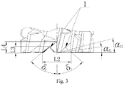
shaped chip pockets 1 are designed on the end cutting edge I in two cutting edge directions which are symmetrical around a cutter axis as a center, and the V-shaped chip pocket 1 presents such a structural shape that a bottom is narrow and a top is wide, which is beneficial for quickly removing the chips of powdery CFRP. To ensure that the chip pocket of the end cutting edge has good chip removal performance and is closely connected with the chip pocket of the end cutting edge, the sizes of a design structure of the V-shaped chip pocket 1 are determined: the bottom width is L1, the top width of the V-shaped chip pocket is L2, the depth of the V-shaped chip pocket is L3 and tilt angles of two side surfaces of the V-shaped chip pocket 1 satisfy δ1=δ2. - The peripheral cutting edge II with variation inverse helical groove is of an asymmetric-and spiral-stagger structure, and m right-
hand flutes 7 and n left-hand flutes 8 are staggered to form a plurality of equidimensional micro-teeth 6; to reduce the vibration of the end cutting edge I and a transition part of peripheral cutting edge during slot milling, a section of peripheral cutting edge II with variation left-hand inverse 8 helical flute angle is designed near the end cutting edge I; the peripheral cutting edge points to the end cutting edge direction and the change relationship of the helical angle of the left-hand flutes 8 is γ1<γ2<γ3. - In view of the problem of corner chipping at the weak edge of micro-teeth, a design method for the micro-tooth configuration of the peripheral cutting edge of the cutter is invented. By determining the key structural parameters of the cutter and the geometrical relationship of the cutter structure, it is known from calculation that the micro-tooth edges are overlapped in forward and backward directions. The overlapping configuration mode of two micro-tooth edges can effectively reduce cutting thickness at the edges, thereby avoiding the phenomenon of easy corner chipping at the weak edges and realizing high-speed, steady and effective processing of the CFRP under large cutting amount. A three-dimensional stereographic cutter is sectioned along an axial direction and then is unfolded; the peripheral cutting edge III with constant inverse helical groove that represents the configuration mode is selected to form a two-dimensional schematic diagram of micro-tooth configuration of the cutter by using a tangential direction and an axial direction to form a coordinate system; the right-
hand flutes 7 and the left-hand flutes 8 are staggered to formmicro-teeth 6; the micro-teeth 6 comprise alower cutting edge 9 and an uppercutting edge 10; in the design process of the cutter, tool geometric parameters are known, i.e., length A of the micro-tooth 6, width B of the right-hand flute 7, helical angle θ of the right-hand flute 7, number Z1 of milling blade and milling cutter diameter D; the configuration mode of themicro-teeth 6 is mainly determined by the following variables: tangential length d of the left-hand flute 8, tangential length c between adjacent micro-teeth 6, helical angle β of the left-hand flute 7, tangential length f of micro-tooth 6, and number Z2 of the left-hand flute 8; specific steps of the design method are as follows: - step 1: calculating the tangential length c between adjacent micro-teeth 6 through the milling cutter diameter D and the number Z1 of milling blade;

- step 2: selecting the tangential length d of the left-
hand flute 8 as an independent variable parameter; establishing a triangle using the width B of the right-hand flute 7 and the tangential length d of the left-hand flute 8 as sides; and calculating the helical angle β of the left-hand flute 8 through the geometrical relationship of the triangle;
micro-tooth 6 and the tangential length f of the micro-tooth 6 as side lengths; and calculating the tangential length f of the micro-tooth and the number Z2 of left-hand flute through the geometrical relationship of the triangle;

- step 3: judging whether the relationship d<c<f is satisfied; if so, covering the
lower cutting edge 9 and the uppercutting edge 10 of each micro-tooth 6 by the cutting edge of a previous micro-tooth 6 so that two edges of each micro-tooth 6 are overlapped; if not, returning tostep 2 to reselect the tangential length d of inverse flute. - The present invention has beneficial effects that a special end cutting edge attached cutter for CFRP with designable micro-tooth configuration is invented. Two parallel V-shaped chip pockets are designed on the end cutting edge of the cutter in two cutting edge directions which are symmetrical around a cutter axis as a center. The chips and the heat at the end cutting edge axis can be rapidly removed in time during slot milling or impenetrable window milling, so as to avoid serious wear of the end cutting edge under the mixing effect of the chips and the heat and reduce the replacement time of the cutter, thereby enhancing surface processing quality and processing efficiency of the bottom of the chip pocket. When milling impenetrable windows and impenetrable slots of the CFRP, the overlapped configuration mode of two micro-tooth edges ensures that the previous micro-tooth always completes partial removal of the material before the material is removed from the micro-tooth edges. Therefore, this configuration mode can reduce the cutting thickness of the two micro-tooth edges, thereby reducing fracture of weak cutting edge and ensuring excellent cutting performance of the micro-teeth under a long cutting stroke and thus enhancing surface processing quality of side walls of the impenetrable slots and the impenetrable windows. The variation helical angle inverse flute chip with transition part from the peripheral cutting edge to the end cutting edge is adopted, which is a passive method to suppress vibration by means of disturbance regenerative chatter effect, which can effectively suppress chatter in high efficiency milling processing. High-quality and high-efficiency processing requirements for CFRP members with different fiber grades, different thicknesses and multiple lamination modes are satisfied.
-
-
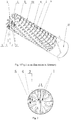
Fig. 1 is a structural schematic diagram of an end cutting edge attached cutter with designable micro-tooth configuration. -
Fig. 2 is a left view of an end cutting edge attached cutter. -
Fig. 3 is an enlarged view of an end cutting edge inFig. 1 . -
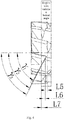
Fig. 4 is a peripheral cutting edge with variation inverse helical groove. -
Fig. 5 is a flow chart of calculation of overlapped configuration mode of two micro-tooth edges. -
Fig. 6 is an expanded view of overlapped configuration mode of two micro-tooth edges. -
Fig. 7(a) is a three-dimensional cutter of anembodiment 1. -
Fig. 7(b) is a three-dimensional cutter of anembodiment 2. -
Fig. 8(a) is wear of a cutter micro-tooth of overlapped configuration mode of two micro-tooth edges. -
Fig. 8(b) is wear of a cutter micro-tooth without considering micro-tooth configuration mode. - In the figures: I end cutting edge; II peripheral cutting edge with variation inverse helical groove; III peripheral cutting edge with constant inverse helical groove; IV shank; 1 V-shaped chip pocket; 2 rake face of end cutting edge; 3 flank face of end cutting edge; 4 secondary flank face of end cutting edge; 5 chip pocket of end cutting edge; 6 micro-tooth; 7 right-hand flute; 8 left-hand flute; 9 lower cutting edge; 10 upper cutting edge; L1 bottom width of V-shaped chip pocket; L2 top width of V-shaped chip pocket; L3 depth of V-type chip pocket; L4 depth of chip pocket of end cutting edge; L5 length of peripheral cutting edge when inverse helical flute angle is γ1; L6 length of peripheral cutting edge when inverse helical flute angle is γ2; L7 length of peripheral cutting edge when inverse helical flute angle is γ3; γ1, γ2 and γ3 variation helical angles of variation left-hand inverse flute; αf1 primary relief angle of end cutting edge; αf2 secondary relief angle of end cutting edge; δ1 left-side tilt angle of V-type chip pocket; δ2 right-side tilt angle of V-type chip pocket; A length of micro-tooth; B width of left-hand flute; θ helical angle of right-hand flute; Z1 number of milling blade; D milling cutter diameter; d tangential length of inverse flute; c tangential length between adjacent micro-teeth; β helical angle of left-hand flute; f tangential length of micro-tooth; and Z2 number of flute.
- Specific embodiments of the present invention are further described below in combination with accompanying drawings and the technical solution.
-
Fig. 2 is a structural schematic diagram of a V-shaped chip pocket protected inclaim 1 of the present invention.Fig. 5 andFig. 6 are design methods for micro-tooth configuration of the peripheral cutting edge of the milling cutter protected inclaim 1 of the present invention. It can be seen from the drawings that the structure of the V-shaped chip pocket can smoothly remove the chips and the cutting heat from the bottom, so as to prevent the chips from being accumulated between the cutting edge and a processing surface and prevent serious wear of the end cutting edge. The design method for micro-tooth configuration ensures that the two micro-tooth edges are configured to be overlapped. This mode can effectively avoid the problem of corner chipping at the micro-tooth edges caused by large cutting thickness. The micro-teeth after corner chipping cannot effectively cut fibers and thus causes that the quality of the processing surface will not meet the requirements. Detailed description of the present invention is described below in detail in combination with accompanying drawings and the technical solution. - The end cutting edge attached cutter for high-speed CFRP milling in the present embodiment is shown in
Fig. 1 . The end cutting edge attached cutter comprises an end cutting edge I, a peripheral cutting edge II with variation inverse helical groove, a peripheral cutting edge III with constant inverse helical groove and a shank IV. - Two parallel V-shaped chip pockets 1 are designed on the end cutting edge I of the end cutting edge attached cutter in two cutting edge directions which are symmetrical around a cutter axis as a center. The bottom width of the V-shaped
chip pocket 1 is L1=2.1 mm; the top width of the V-shaped chip pocket is L2=3.8 mm; the depth of the V-shaped chip pocket is L3=1.5 mm and tilt angles of two side surfaces of the V-shapedchip pocket 1 satisfy δ1=δ2=50°; a primary relief angle αf1 of the end cutting edge is 7°; and a secondary relief angle αf2 of the end cutting edge is 14°. The peripheral cutting edge II with variation inverse helical groove is of an asymmetric-and spiral-stagger structure. A section of peripheral cutting edge with variation helical angle is designed near the end cutting edge. The peripheral cutting edge points to the end cutting edge direction. When the helical angle of the left-hand flute 8 is γ1=66.7°, a corresponding length of the peripheral cutting edge is L5=0.5 mm; when the helical angle of theflute 8 is γ2=67.5°, a corresponding length of the peripheral cutting edge is L6=0.4 mm and when the helical angle of theflute 8 is γ3=75.7°, a corresponding length of the peripheral cutting edge is L7=0.5 mm. - In the design of the cutter, considering reduction of burrs and axial force, basic tool geometric parameters are determined as follows: helical angle θ of the right-hand flute is 15°, length A of the
micro-tooth 6 is 1.3 mm, width B of the flute is 0.8 mm, number Z1 of milling blade is 12 and milling cutter diameter D is 10 mm; tangential lengths of inverse flute are respectively selected as follows: d1=2mm and d2=2.3mm; tangential length c between adjacent micro-teeth, helical angle β of the left-hand flute, tangential length f of micro-tooth and number Z1 of the flute are determined; and several different configuration modes are analyzed. Specific steps of the design method are as follows: - step 1: calculating the tangential length c between adjacent micro-teeth as 2.618 mm through the milling cutter diameter D and the number Z1 of milling blade in accordance with formula (1);
- step 2: respectively selecting tangential lengths of inverse flute as follows: d1=2mm and d2=2.3mm; and in accordance with formulas (2), (3) and (4), respectively calculating β1=66.7°, β2=69.7°, f1=3.25mm, f2=3.7375mm, Z21=6 and Z22=5; and
- step 3: analyzing the micro-tooth configuration mode under different values of the tangential length d of inverse flute through the geometric parameters calculated in
step 1 and step 2:
At this moment, d1<c<f1 and d2<c<f2 are satisfied. Such configuration mode that the upper cutting edge and the lower cutting edge of the micro-tooth are overlapped. Based on three-dimensional mapping software SolidWorks, two cutters can be designed, as shown inFigs. 7(a) and(b) , and each micro-tooth has alower edge overlap 4 and anupper edge overlap 5. - To verify the application effect of the special end cutting edge attached cutter for CFRP which considers micro-tooth configuration design, when spindle speed is 6000 rpm and feed rate is 800 mm/min, the CFRP with a thickness of 8mm is subjected to an impenetrable slot milling experiment. The experiment finds: in the milling process, there is no phenomenon of corner chipping at the micro-tooth edges of the peripheral cutting edge of the cutter which considers micro-tooth configuration design, as shown in
Fig. 8(a) ; there is a phenomenon of corner chipping at the micro-tooth edges of the peripheral cutting edge of the cutter which does not consider micro-tooth configuration design, as shown inFig. 8(b) . - The special end cutting edge attached cutter for CFRP with designable micro-tooth configuration in the present invention is especially suitable for milling processing of impenetrable slots, impenetrable windows and special-shaped impenetrable hole structures in CFRP members. The parallel V-shaped chip pockets are designed on the end cutting edge of the cutter in two cutting edge directions which are symmetrical around a cutter axis as a center, so as to effectively enhance the chip removal and heat radiation performance of the cutter, reduce the wear of the chips to the end cutting edge and ensure the processing quality of bottom surfaces of the impenetrable windows and the impenetrable slots. The peripheral cutting edge with variation inverse helical groove in the cutter can reduce cutting tool vibration during milling processing. Considering reasonable micro-tooth configuration of the peripheral cutting edge of the cutter may avoid the problem of corner chipping on two micro-tooth edges caused by large cutting thickness, thereby effectively protecting the edges with poor micro-tooth strength and ensuring that the micro-teeth of the peripheral cutting edge of the cutter have long-term excellent cutting performance. Therefore, the cutter of the present invention is intended to enhance the service life of the cutter with respect to the milling processing of the CFRP, and its industrial application not only can reduce tool change time and increase processing efficiency, but also can reduce the use cost and finally enhance economic benefits of enterprises.
Claims (1)
- A special end cutting edge attached cutter for carbon fiber reinforced polymer/plastic with designable micro-tooth configuration, wherein the special end cutting edge attached cutter with designable micro-tooth configuration for CFRP comprises an end cutting edge (I), a peripheral cutting edge (II) with variation inverse helical groove, a peripheral cutting edge (III) with constant inverse helical groove and a shank (IV);
wherein the end cutting edge (I) is designed with a rake face (2) of end cutting edge, a flank face (3) of end cutting edge, and a secondary flank face (4) of end cutting edge, and also has a chip pocket (5) of end cutting edge; parallel V-shaped chip pockets (1) are designed on the end cutting edge (I) in two cutting edge directions which are symmetrical around a cutter axis as a center, and the V-shaped chip pocket (1) presents such a structural shape that a bottom is narrow and a top is wide; to ensure that the V-shaped chip pocket (1) has good chip removal performance and is closely connected with the chip pocket (5) of end cutting edge, the sizes of a design structure of the V-shaped chip pocket (1) are determined: the bottom width is L1, the top width of V-shaped chip pocket is L2, the depth of the V-shaped chip pocket is L3 and tilt angles of two side surfaces of the V-shaped chip pocket (1) satisfy δ1=δ2;
the peripheral cutting edge (II) with variation inverse helical groove is of an asymmetric-and spiral-stagger structure, and m right-hand flutes (7) and n left-hand flutes (8) are staggered to form a plurality of equidimensional micro-teeth (6); to reduce the vibration of the end cutting edge (I) and a transition part of peripheral cutting edge during slot milling, a section of peripheral cutting edge (II) with variation left-hand inverse helical flute angle is designed near the end cutting edge (I); the peripheral cutting edge (II) with variation left-hand inverse helical flute angle points to the end cutting edge direction and the change relationship of the helical angle of the left-hand flutes (8) is γ1<γ2<γ3;
a three-dimensional stereographic cutter is sectioned along an axial direction and then is unfolded; the peripheral cutting edge (III) with constant inverse helical groove that represents the configuration mode is selected to form a two-dimensional schematic diagram of micro-tooth configuration of the cutter by using a tangential direction and an axial direction to form a coordinate system; the right-hand flutes (7) and the left-hand flutes (8) are staggered to form micro-teeth (6); the micro-teeth (6) comprise a lower cutting edge (9) and an upper cutting edge (10); in the design process of the cutter, tool geometric parameters are known, i.e., length A of the micro-tooth (6), width B of the right-hand flute (7), helical angle θ of the right-hand flute (7), number of milling blade Z 1 and milling cutter diameter D; the configuration mode of the micro-teeth (6) is mainly determined by the following variables: tangential length d of the left-hand flute (8), tangential length c between adjacent micro-teeth (6), helical angle β of the left-hand flute (7), tangential length f of micro-tooth (6), and number Z 2 of the left-hand flute (8); specific steps of the design method are as follows:step 1: calculating the tangential length c between adjacent micro-teeth (6) through the milling cutter diameter D and the number Z 1 of milling blade; step 2: selecting the tangential length d of the left-hand flute (8) as an independent variable parameter; establishing a triangle using the width B of the right-hand flute (7) and the tangential length d of the left-hand flute (8) as sides; and calculating the helical angle β of the left-hand flute (8) through the geometrical relationship of the triangle;

 step 3: judging whether the relationship d<c<f is satisfied; if so, covering the lower cutting edge (9) and the upper cutting edge (10) of each micro-tooth (6) by the cutting edge of a previous micro-tooth (6) so that two edges of each micro-tooth (6) are overlapped; if not, returning to step 2 to reselect the tangential length d of inverse flute.
Applications Claiming Priority (2)
| Application Number | Priority Date | Filing Date | Title |
|---|---|---|---|
| CN201710808999.6A CN107363312B (en) | 2017-09-11 | 2017-09-11 | End Mills with End Flute for High Speed Milling of Carbon Fiber Composites |
| PCT/CN2018/087193 WO2019047557A1 (en) | 2017-09-11 | 2018-05-17 | Micro-teeth arrangement designable end mill having tip blade for dedicated use with carbon fiber composite material |
Publications (3)
| Publication Number | Publication Date |
|---|---|
| EP3533547A1 true EP3533547A1 (en) | 2019-09-04 |
| EP3533547A4 EP3533547A4 (en) | 2020-01-01 |
| EP3533547B1 EP3533547B1 (en) | 2021-09-15 |
Family
ID=60311484
Family Applications (1)
| Application Number | Title | Priority Date | Filing Date |
|---|---|---|---|
| EP18854324.3A Not-in-force EP3533547B1 (en) | 2017-09-11 | 2018-05-17 | Micro-teeth arrangement designable end mill having tip blade for dedicated use with carbon fiber composite material |
Country Status (5)
| Country | Link |
|---|---|
| US (1) | US20190299304A1 (en) |
| EP (1) | EP3533547B1 (en) |
| JP (1) | JP6775855B2 (en) |
| CN (1) | CN107363312B (en) |
| WO (1) | WO2019047557A1 (en) |
Cited By (2)
| Publication number | Priority date | Publication date | Assignee | Title |
|---|---|---|---|---|
| CN112139573A (en) * | 2020-08-21 | 2020-12-29 | 成都飞机工业(集团)有限责任公司 | Numerical control machining method for preventing sharp corner of carbon fiber part from layering |
| WO2021176069A1 (en) * | 2020-03-06 | 2021-09-10 | ATA Tools Limited | Burr |
Families Citing this family (34)
| Publication number | Priority date | Publication date | Assignee | Title |
|---|---|---|---|---|
| DE102017121354A1 (en) * | 2017-09-14 | 2019-03-14 | Gühring KG | Roughening tool and method for its production |
| KR102365447B1 (en) * | 2018-02-02 | 2022-02-18 | 가부시키가이샤 몰디노 | End mills and machining methods |
| CN108723453B (en) * | 2018-04-13 | 2020-01-10 | 西安工业大学 | End milling cutter with wave-shaped edge |
| CN108405946B (en) * | 2018-05-17 | 2019-04-16 | 大连理工大学 | Inhibit micro- tooth row cloth design method of the micro- tooth milling cutter cutting edge edge breakage of multiple-cutting-edge |
| CN108672779A (en) * | 2018-06-07 | 2018-10-19 | 三砥新材(深圳)有限公司 | milling cutter for processing graphite workpiece |
| CN109304507B (en) * | 2018-10-19 | 2024-04-05 | 厦门金鹭特种合金有限公司 | PCD milling cutter for processing carbon fiber composite material |
| CN109648125B (en) * | 2019-01-25 | 2020-06-16 | 大连理工大学 | Multi-tooth design method capable of realizing alternate cutting of left-handed cutting edge and right-handed cutting edge |
| CN109794634A (en) * | 2019-03-05 | 2019-05-24 | 苏州阿诺精密切削技术有限公司 | A kind of rough machining integral ceramic milling cutter |
| CN110052655A (en) * | 2019-05-27 | 2019-07-26 | 金富中 | A kind of drill mill of end sword not equal part angle |
| CN110524040A (en) * | 2019-07-26 | 2019-12-03 | 中国航空工业集团公司济南特种结构研究所 | A kind of processing method of step groove |
| CN110497005B (en) * | 2019-08-29 | 2020-07-10 | 哈尔滨理工大学 | A kind of carbon fiber composite material high-efficiency hole-making tool and inclination angle hole-making method |
| CN110587004A (en) * | 2019-09-12 | 2019-12-20 | 闵国富 | High-precision milling cutter for fiber composite material |
| CN110877120B (en) * | 2019-12-24 | 2025-04-18 | 常州利德切削技术有限公司 | A high-efficiency chip-splitting milling cutter for deep hole enlargement |
| CN111250768B (en) * | 2020-03-31 | 2021-09-10 | 湖南泰嘉新材料科技股份有限公司 | Milling cutter for processing special-shaped bottom edge of band saw blade, processing device and processing method |
| JP7727657B2 (en) * | 2020-04-02 | 2025-08-21 | セコ ツールズ アクティエボラーグ | A rotary cutting tool having continuous major grooves and discontinuous minor grooves intersecting to form a quadrilateral surface portion. |
| CN113100013B (en) * | 2021-04-01 | 2022-08-09 | 北京理工大学 | Design method of two-section-edge inserted tooth type special high-speed tapping cutter |
| CN113094828B (en) * | 2021-04-01 | 2022-07-19 | 北京理工大学 | Design method of special high-speed integral tapping cutter |
| CN113649632B (en) * | 2021-08-23 | 2023-10-13 | 哈尔滨理工大学 | A carbon fiber composite ultrasonic bidirectional spiral milling cutter and its grinding method |
| CN113664269B (en) * | 2021-09-14 | 2024-06-14 | 国宏工具系统(无锡)股份有限公司 | Diamond coating cutter for efficiently processing composite material |
| CN113894341A (en) * | 2021-10-27 | 2022-01-07 | 湘潭大学 | A ceramic milling cutter suitable for rough machining |
| CN114160856A (en) * | 2021-12-10 | 2022-03-11 | 大连理工大学 | A Half-width Buffer Impact Plunge Milling Tool |
| CN114101758B (en) * | 2021-12-23 | 2023-03-31 | 北京新风航天装备有限公司 | Self-guiding flat-bottom countersink drill for flat-bottom blind hole |
| CN114840932B (en) * | 2022-03-01 | 2023-09-15 | 江苏师范大学 | Multi-factor coupling method to improve prediction accuracy of surface roughness of TC4 titanium alloy |
| CN114951782A (en) * | 2022-07-01 | 2022-08-30 | 河南四方达超硬材料股份有限公司 | A milling cutter for machining composite materials |
| CN115070518B (en) * | 2022-07-08 | 2024-04-16 | 哈尔滨工业大学(深圳) | Ball head micro milling cutter with array micro tooth structure and preparation method thereof |
| CN115921964B (en) * | 2022-11-01 | 2023-10-03 | 南京航空航天大学 | A milling tool and its use and manufacturing method |
| CN116140677B (en) * | 2023-01-16 | 2024-09-10 | 哈尔滨理工大学 | Design method of gradual change spiral integral vertical milling blade line |
| US12350745B2 (en) * | 2023-02-01 | 2025-07-08 | Sumitomo Electric Hardmetal Corp. | Cutting tool |
| CN116551046A (en) * | 2023-05-19 | 2023-08-08 | 哈尔滨理工大学 | A hook groove chamfering edge milling cutter for machining CFRP with ultrasonic vibration assisted helical milling |
| CN116756869B (en) * | 2023-06-12 | 2023-11-28 | 哈尔滨理工大学 | Design method of discrete edge end mill with variable chip dividing groove parameters |
| CN116765488B (en) * | 2023-06-25 | 2025-09-02 | 大连理工大学 | A ball-end milling cutter with a micro-groove structure for reducing cutting forces in surface machining of carbon fiber composites |
| DE102023124921B3 (en) | 2023-09-14 | 2025-02-13 | MAPAL Fabrik für Präzisionswerkzeuge Dr. Kress KG | tool for machining a workpiece |
| CN118751970B (en) * | 2024-09-05 | 2024-12-27 | 哈尔滨理工大学 | Drilling and milling integrated tool for inhibiting burrs and design method |
| CN118751977B (en) * | 2024-09-06 | 2024-12-10 | 哈尔滨理工大学 | Crescent cutting edge hard alloy milling cutter and parameter design method thereof |
Family Cites Families (25)
| Publication number | Priority date | Publication date | Assignee | Title |
|---|---|---|---|---|
| DE10238334A1 (en) * | 2002-08-16 | 2004-02-26 | Sandvik Ab | Drilling or milling tool and method for its production |
| JPS5947110A (en) * | 1982-09-08 | 1984-03-16 | Nippon Kogu Seisakusho:Kk | End mill |
| JPH05261614A (en) * | 1992-03-19 | 1993-10-12 | Kobe Steel Ltd | End mill with nick |
| JPH10263915A (en) * | 1997-03-25 | 1998-10-06 | Hitachi Tool Eng Co Ltd | Cemented carbide end mill |
| WO2007125613A1 (en) * | 2006-04-28 | 2007-11-08 | Union Tool Co. | Rotary cutting tool |
| US20070297864A1 (en) * | 2006-06-23 | 2007-12-27 | De Boer Tools Inc. | Fluted Rotary Cutting Tool |
| CN101623778B (en) * | 2009-08-13 | 2011-08-03 | 沈阳飞机工业(集团)有限公司 | Integral carbide goldfish scale milling cutter |
| KR20120023466A (en) * | 2010-09-03 | 2012-03-13 | 태양파워(주) | Complex end-mill |
| CN202517100U (en) * | 2011-12-01 | 2012-11-07 | 贵州西南工具(集团)有限公司 | High-stability end mill |
| CN103071840A (en) * | 2013-01-31 | 2013-05-01 | 哈尔滨理工大学 | Pineapple end mill for carbon fiber reinforced composite |
| CN104338994A (en) * | 2013-07-30 | 2015-02-11 | 常州耐之力刀具制造有限公司 | Two-edge round-nose end mill |
| DE102013015261A1 (en) * | 2013-09-16 | 2015-03-19 | Franz Haimer Maschinenbau Kg | Cutter with cord made of a special tooth profile |
| CN104551164A (en) * | 2013-10-17 | 2015-04-29 | 常州埃特法斯工具有限公司 | Arc-angle end mill |
| CN103567524A (en) * | 2013-11-14 | 2014-02-12 | 无锡蠡湖叶轮制造有限公司 | End mill having chip breaking function |
| JP6228449B2 (en) * | 2013-12-24 | 2017-11-08 | 有限会社栄進機工 | Unequal lead end mill |
| JP6419453B2 (en) * | 2014-04-18 | 2018-11-07 | 三菱日立ツール株式会社 | Cutting tool and method of manufacturing cutting tool |
| CN204234845U (en) * | 2014-07-30 | 2015-04-01 | 常州创伟工具制造有限公司 | A kind of three sword aluminium milling cutters |
| PL3233340T3 (en) * | 2014-12-15 | 2024-02-05 | Iscar Ltd. | Rotary cutting tool having a predetermined number of left and right handed helical flutes and end face cutting teeth |
| CN104959667B (en) * | 2015-05-12 | 2018-03-23 | 哈尔滨理工大学 | Knife face band Unequal distance arc head milling cutter and method for grinding after a kind of eccentric shape |
| DE102015119355B4 (en) * | 2015-11-10 | 2018-09-20 | Albert Knebel Holding Gmbh | cutting tool |
| CN105364153B (en) * | 2015-11-26 | 2017-12-26 | 株洲钻石切削刀具股份有限公司 | A kind of square end mill |
| US10272504B2 (en) * | 2016-02-02 | 2019-04-30 | Sandvik Intellectual Property | Tool with right-hand and left-hand cutting features extending along the full length of the cutting zone |
| CN106270700A (en) * | 2016-09-06 | 2017-01-04 | 大连理工大学 | Multiple-cutting-edge micro-tooth milling cutter for carbon fibre composite high speed milling |
| CN106270697A (en) * | 2016-10-10 | 2017-01-04 | 刘浩 | Circumferential cutting edge is the milling cutter of parabolic shape |
| EP3348340B1 (en) * | 2017-01-16 | 2020-01-01 | Seco Tools Ab | Rotary cutting tool |
-
2017
- 2017-09-11 CN CN201710808999.6A patent/CN107363312B/en active Active
-
2018
- 2018-05-17 US US16/465,960 patent/US20190299304A1/en not_active Abandoned
- 2018-05-17 WO PCT/CN2018/087193 patent/WO2019047557A1/en not_active Ceased
- 2018-05-17 EP EP18854324.3A patent/EP3533547B1/en not_active Not-in-force
- 2018-05-17 JP JP2019555845A patent/JP6775855B2/en not_active Expired - Fee Related
Cited By (2)
| Publication number | Priority date | Publication date | Assignee | Title |
|---|---|---|---|---|
| WO2021176069A1 (en) * | 2020-03-06 | 2021-09-10 | ATA Tools Limited | Burr |
| CN112139573A (en) * | 2020-08-21 | 2020-12-29 | 成都飞机工业(集团)有限责任公司 | Numerical control machining method for preventing sharp corner of carbon fiber part from layering |
Also Published As
| Publication number | Publication date |
|---|---|
| EP3533547B1 (en) | 2021-09-15 |
| US20190299304A1 (en) | 2019-10-03 |
| CN107363312A (en) | 2017-11-21 |
| WO2019047557A1 (en) | 2019-03-14 |
| CN107363312B (en) | 2019-04-23 |
| JP2020516473A (en) | 2020-06-11 |
| EP3533547A4 (en) | 2020-01-01 |
| JP6775855B2 (en) | 2020-10-28 |
Similar Documents
| Publication | Publication Date | Title |
|---|---|---|
| EP3533547B1 (en) | Micro-teeth arrangement designable end mill having tip blade for dedicated use with carbon fiber composite material | |
| EP3756803B1 (en) | Vertical blade double-ladder micro-tooth cutter for preparing high-quality holes of composite material and hybrid stack structure thereof | |
| WO2009122937A1 (en) | End mill | |
| CN106270700A (en) | Multiple-cutting-edge micro-tooth milling cutter for carbon fibre composite high speed milling | |
| CN106624080B (en) | A kind of micro- tooth Double-margin brill ream one drill bit of ladder | |
| CN109648125B (en) | Multi-tooth design method capable of realizing alternate cutting of left-handed cutting edge and right-handed cutting edge | |
| CN102756252A (en) | Method for machining slotted holes on carbon fiber laminated boards | |
| CN204321316U (en) | Shock resistance type metal cold saw | |
| CN106312156A (en) | Cutting angle acquiring method for restraining milling burr of carbon fiber laminate | |
| CN107398599B (en) | Super-precision reamer | |
| CN112620760B (en) | Combination milling cutter with PCD insert and micro blade | |
| CN208644194U (en) | A kind of screw-on cutter | |
| CN108405946A (en) | Inhibit micro- tooth row cloth design method of the micro- tooth milling cutter cutting edge edge breakage of multiple-cutting-edge | |
| CN103737090A (en) | Finish machining rotating cutter | |
| CN204686045U (en) | A kind of PCD gang tool for machining composite material | |
| CN104227093A (en) | Drill point centering countersinking cutter | |
| JP2015182196A (en) | ball end mill | |
| CN103894662A (en) | Special tool for helically milling hole in laminated material | |
| Wertheim et al. | Modifications of the cutting edge geometry and chip formation in milling | |
| CN108393521B (en) | A preferred method for up-and-down milling of carbon fiber composite materials | |
| CN202224730U (en) | High-efficiency high-speed finish machining cutting hard alloy milling cutter | |
| JP5846683B2 (en) | Drill for processing FRP and metal | |
| CN206335180U (en) | A compound high-hardness milling cutter for end milling and side milling | |
| CN120790999B (en) | Step drill | |
| CN103192099B (en) | Dual-purpose turning and milling blade special for extreme heavy axial forging efficient bullnose |
Legal Events
| Date | Code | Title | Description |
|---|---|---|---|
| STAA | Information on the status of an ep patent application or granted ep patent |
Free format text: STATUS: THE INTERNATIONAL PUBLICATION HAS BEEN MADE |
|
| PUAI | Public reference made under article 153(3) epc to a published international application that has entered the european phase |
Free format text: ORIGINAL CODE: 0009012 |
|
| STAA | Information on the status of an ep patent application or granted ep patent |
Free format text: STATUS: REQUEST FOR EXAMINATION WAS MADE |
|
| 17P | Request for examination filed |
Effective date: 20190531 |
|
| AK | Designated contracting states |
Kind code of ref document: A1 Designated state(s): AL AT BE BG CH CY CZ DE DK EE ES FI FR GB GR HR HU IE IS IT LI LT LU LV MC MK MT NL NO PL PT RO RS SE SI SK SM TR |
|
| AX | Request for extension of the european patent |
Extension state: BA ME |
|
| A4 | Supplementary search report drawn up and despatched |
Effective date: 20191202 |
|
| RIC1 | Information provided on ipc code assigned before grant |
Ipc: B23C 5/16 20060101ALI20191126BHEP Ipc: B23C 5/10 20060101AFI20191126BHEP |
|
| STAA | Information on the status of an ep patent application or granted ep patent |
Free format text: STATUS: EXAMINATION IS IN PROGRESS |
|
| 17Q | First examination report despatched |
Effective date: 20200727 |
|
| DAV | Request for validation of the european patent (deleted) | ||
| DAX | Request for extension of the european patent (deleted) | ||
| GRAP | Despatch of communication of intention to grant a patent |
Free format text: ORIGINAL CODE: EPIDOSNIGR1 |
|
| STAA | Information on the status of an ep patent application or granted ep patent |
Free format text: STATUS: GRANT OF PATENT IS INTENDED |
|
| INTG | Intention to grant announced |
Effective date: 20210617 |
|
| GRAS | Grant fee paid |
Free format text: ORIGINAL CODE: EPIDOSNIGR3 |
|
| GRAA | (expected) grant |
Free format text: ORIGINAL CODE: 0009210 |
|
| STAA | Information on the status of an ep patent application or granted ep patent |
Free format text: STATUS: THE PATENT HAS BEEN GRANTED |
|
| AK | Designated contracting states |
Kind code of ref document: B1 Designated state(s): AL AT BE BG CH CY CZ DE DK EE ES FI FR GB GR HR HU IE IS IT LI LT LU LV MC MK MT NL NO PL PT RO RS SE SI SK SM TR |
|
| REG | Reference to a national code |
Ref country code: CH Ref legal event code: EP |
|
| REG | Reference to a national code |
Ref country code: DE Ref legal event code: R096 Ref document number: 602018023763 Country of ref document: DE |
|
| REG | Reference to a national code |
Ref country code: IE Ref legal event code: FG4D |
|
| REG | Reference to a national code |
Ref country code: AT Ref legal event code: REF Ref document number: 1430149 Country of ref document: AT Kind code of ref document: T Effective date: 20211015 |
|
| REG | Reference to a national code |
Ref country code: LT Ref legal event code: MG9D |
|
| REG | Reference to a national code |
Ref country code: NL Ref legal event code: MP Effective date: 20210915 |
|
| PG25 | Lapsed in a contracting state [announced via postgrant information from national office to epo] |
Ref country code: LT Free format text: LAPSE BECAUSE OF FAILURE TO SUBMIT A TRANSLATION OF THE DESCRIPTION OR TO PAY THE FEE WITHIN THE PRESCRIBED TIME-LIMIT Effective date: 20210915 Ref country code: BG Free format text: LAPSE BECAUSE OF FAILURE TO SUBMIT A TRANSLATION OF THE DESCRIPTION OR TO PAY THE FEE WITHIN THE PRESCRIBED TIME-LIMIT Effective date: 20211215 Ref country code: HR Free format text: LAPSE BECAUSE OF FAILURE TO SUBMIT A TRANSLATION OF THE DESCRIPTION OR TO PAY THE FEE WITHIN THE PRESCRIBED TIME-LIMIT Effective date: 20210915 Ref country code: NO Free format text: LAPSE BECAUSE OF FAILURE TO SUBMIT A TRANSLATION OF THE DESCRIPTION OR TO PAY THE FEE WITHIN THE PRESCRIBED TIME-LIMIT Effective date: 20211215 Ref country code: FI Free format text: LAPSE BECAUSE OF FAILURE TO SUBMIT A TRANSLATION OF THE DESCRIPTION OR TO PAY THE FEE WITHIN THE PRESCRIBED TIME-LIMIT Effective date: 20210915 Ref country code: RS Free format text: LAPSE BECAUSE OF FAILURE TO SUBMIT A TRANSLATION OF THE DESCRIPTION OR TO PAY THE FEE WITHIN THE PRESCRIBED TIME-LIMIT Effective date: 20210915 Ref country code: SE Free format text: LAPSE BECAUSE OF FAILURE TO SUBMIT A TRANSLATION OF THE DESCRIPTION OR TO PAY THE FEE WITHIN THE PRESCRIBED TIME-LIMIT Effective date: 20210915 |
|
| REG | Reference to a national code |
Ref country code: AT Ref legal event code: MK05 Ref document number: 1430149 Country of ref document: AT Kind code of ref document: T Effective date: 20210915 |
|
| PG25 | Lapsed in a contracting state [announced via postgrant information from national office to epo] |
Ref country code: LV Free format text: LAPSE BECAUSE OF FAILURE TO SUBMIT A TRANSLATION OF THE DESCRIPTION OR TO PAY THE FEE WITHIN THE PRESCRIBED TIME-LIMIT Effective date: 20210915 Ref country code: GR Free format text: LAPSE BECAUSE OF FAILURE TO SUBMIT A TRANSLATION OF THE DESCRIPTION OR TO PAY THE FEE WITHIN THE PRESCRIBED TIME-LIMIT Effective date: 20211216 |
|
| PG25 | Lapsed in a contracting state [announced via postgrant information from national office to epo] |
Ref country code: AT Free format text: LAPSE BECAUSE OF FAILURE TO SUBMIT A TRANSLATION OF THE DESCRIPTION OR TO PAY THE FEE WITHIN THE PRESCRIBED TIME-LIMIT Effective date: 20210915 |
|
| PG25 | Lapsed in a contracting state [announced via postgrant information from national office to epo] |
Ref country code: IS Free format text: LAPSE BECAUSE OF FAILURE TO SUBMIT A TRANSLATION OF THE DESCRIPTION OR TO PAY THE FEE WITHIN THE PRESCRIBED TIME-LIMIT Effective date: 20220115 Ref country code: SM Free format text: LAPSE BECAUSE OF FAILURE TO SUBMIT A TRANSLATION OF THE DESCRIPTION OR TO PAY THE FEE WITHIN THE PRESCRIBED TIME-LIMIT Effective date: 20210915 Ref country code: SK Free format text: LAPSE BECAUSE OF FAILURE TO SUBMIT A TRANSLATION OF THE DESCRIPTION OR TO PAY THE FEE WITHIN THE PRESCRIBED TIME-LIMIT Effective date: 20210915 Ref country code: RO Free format text: LAPSE BECAUSE OF FAILURE TO SUBMIT A TRANSLATION OF THE DESCRIPTION OR TO PAY THE FEE WITHIN THE PRESCRIBED TIME-LIMIT Effective date: 20210915 Ref country code: PT Free format text: LAPSE BECAUSE OF FAILURE TO SUBMIT A TRANSLATION OF THE DESCRIPTION OR TO PAY THE FEE WITHIN THE PRESCRIBED TIME-LIMIT Effective date: 20220117 Ref country code: PL Free format text: LAPSE BECAUSE OF FAILURE TO SUBMIT A TRANSLATION OF THE DESCRIPTION OR TO PAY THE FEE WITHIN THE PRESCRIBED TIME-LIMIT Effective date: 20210915 Ref country code: NL Free format text: LAPSE BECAUSE OF FAILURE TO SUBMIT A TRANSLATION OF THE DESCRIPTION OR TO PAY THE FEE WITHIN THE PRESCRIBED TIME-LIMIT Effective date: 20210915 Ref country code: ES Free format text: LAPSE BECAUSE OF FAILURE TO SUBMIT A TRANSLATION OF THE DESCRIPTION OR TO PAY THE FEE WITHIN THE PRESCRIBED TIME-LIMIT Effective date: 20210915 Ref country code: EE Free format text: LAPSE BECAUSE OF FAILURE TO SUBMIT A TRANSLATION OF THE DESCRIPTION OR TO PAY THE FEE WITHIN THE PRESCRIBED TIME-LIMIT Effective date: 20210915 Ref country code: CZ Free format text: LAPSE BECAUSE OF FAILURE TO SUBMIT A TRANSLATION OF THE DESCRIPTION OR TO PAY THE FEE WITHIN THE PRESCRIBED TIME-LIMIT Effective date: 20210915 Ref country code: AL Free format text: LAPSE BECAUSE OF FAILURE TO SUBMIT A TRANSLATION OF THE DESCRIPTION OR TO PAY THE FEE WITHIN THE PRESCRIBED TIME-LIMIT Effective date: 20210915 |
|
| REG | Reference to a national code |
Ref country code: DE Ref legal event code: R097 Ref document number: 602018023763 Country of ref document: DE |
|
| PLBE | No opposition filed within time limit |
Free format text: ORIGINAL CODE: 0009261 |
|
| STAA | Information on the status of an ep patent application or granted ep patent |
Free format text: STATUS: NO OPPOSITION FILED WITHIN TIME LIMIT |
|
| PG25 | Lapsed in a contracting state [announced via postgrant information from national office to epo] |
Ref country code: DK Free format text: LAPSE BECAUSE OF FAILURE TO SUBMIT A TRANSLATION OF THE DESCRIPTION OR TO PAY THE FEE WITHIN THE PRESCRIBED TIME-LIMIT Effective date: 20210915 |
|
| 26N | No opposition filed |
Effective date: 20220616 |
|
| PG25 | Lapsed in a contracting state [announced via postgrant information from national office to epo] |
Ref country code: SI Free format text: LAPSE BECAUSE OF FAILURE TO SUBMIT A TRANSLATION OF THE DESCRIPTION OR TO PAY THE FEE WITHIN THE PRESCRIBED TIME-LIMIT Effective date: 20210915 |
|
| REG | Reference to a national code |
Ref country code: CH Ref legal event code: PL |
|
| REG | Reference to a national code |
Ref country code: BE Ref legal event code: MM Effective date: 20220531 |
|
| PG25 | Lapsed in a contracting state [announced via postgrant information from national office to epo] |
Ref country code: MC Free format text: LAPSE BECAUSE OF FAILURE TO SUBMIT A TRANSLATION OF THE DESCRIPTION OR TO PAY THE FEE WITHIN THE PRESCRIBED TIME-LIMIT Effective date: 20210915 Ref country code: LU Free format text: LAPSE BECAUSE OF NON-PAYMENT OF DUE FEES Effective date: 20220517 Ref country code: LI Free format text: LAPSE BECAUSE OF NON-PAYMENT OF DUE FEES Effective date: 20220531 Ref country code: IT Free format text: LAPSE BECAUSE OF FAILURE TO SUBMIT A TRANSLATION OF THE DESCRIPTION OR TO PAY THE FEE WITHIN THE PRESCRIBED TIME-LIMIT Effective date: 20210915 Ref country code: CH Free format text: LAPSE BECAUSE OF NON-PAYMENT OF DUE FEES Effective date: 20220531 |
|
| PG25 | Lapsed in a contracting state [announced via postgrant information from national office to epo] |
Ref country code: IE Free format text: LAPSE BECAUSE OF NON-PAYMENT OF DUE FEES Effective date: 20220517 |
|
| PG25 | Lapsed in a contracting state [announced via postgrant information from national office to epo] |
Ref country code: BE Free format text: LAPSE BECAUSE OF NON-PAYMENT OF DUE FEES Effective date: 20220531 |
|
| PG25 | Lapsed in a contracting state [announced via postgrant information from national office to epo] |
Ref country code: HU Free format text: LAPSE BECAUSE OF FAILURE TO SUBMIT A TRANSLATION OF THE DESCRIPTION OR TO PAY THE FEE WITHIN THE PRESCRIBED TIME-LIMIT; INVALID AB INITIO Effective date: 20180517 |
|
| PG25 | Lapsed in a contracting state [announced via postgrant information from national office to epo] |
Ref country code: MK Free format text: LAPSE BECAUSE OF FAILURE TO SUBMIT A TRANSLATION OF THE DESCRIPTION OR TO PAY THE FEE WITHIN THE PRESCRIBED TIME-LIMIT Effective date: 20210915 Ref country code: CY Free format text: LAPSE BECAUSE OF FAILURE TO SUBMIT A TRANSLATION OF THE DESCRIPTION OR TO PAY THE FEE WITHIN THE PRESCRIBED TIME-LIMIT Effective date: 20210915 |
|
| PG25 | Lapsed in a contracting state [announced via postgrant information from national office to epo] |
Ref country code: TR Free format text: LAPSE BECAUSE OF FAILURE TO SUBMIT A TRANSLATION OF THE DESCRIPTION OR TO PAY THE FEE WITHIN THE PRESCRIBED TIME-LIMIT Effective date: 20210915 |
|
| PGFP | Annual fee paid to national office [announced via postgrant information from national office to epo] |
Ref country code: GB Payment date: 20240530 Year of fee payment: 7 |
|
| PGFP | Annual fee paid to national office [announced via postgrant information from national office to epo] |
Ref country code: DE Payment date: 20240531 Year of fee payment: 7 |
|
| PGFP | Annual fee paid to national office [announced via postgrant information from national office to epo] |
Ref country code: FR Payment date: 20240524 Year of fee payment: 7 |
|
| PG25 | Lapsed in a contracting state [announced via postgrant information from national office to epo] |
Ref country code: MT Free format text: LAPSE BECAUSE OF FAILURE TO SUBMIT A TRANSLATION OF THE DESCRIPTION OR TO PAY THE FEE WITHIN THE PRESCRIBED TIME-LIMIT Effective date: 20210915 |
|
| REG | Reference to a national code |
Ref country code: DE Ref legal event code: R119 Ref document number: 602018023763 Country of ref document: DE |
|
| GBPC | Gb: european patent ceased through non-payment of renewal fee |
Effective date: 20250517 |
|
| PG25 | Lapsed in a contracting state [announced via postgrant information from national office to epo] |
Ref country code: GB Free format text: LAPSE BECAUSE OF NON-PAYMENT OF DUE FEES Effective date: 20250517 |
|
| PG25 | Lapsed in a contracting state [announced via postgrant information from national office to epo] |
Ref country code: DE Free format text: LAPSE BECAUSE OF NON-PAYMENT OF DUE FEES Effective date: 20251202 |
|
| PG25 | Lapsed in a contracting state [announced via postgrant information from national office to epo] |
Ref country code: FR Free format text: LAPSE BECAUSE OF NON-PAYMENT OF DUE FEES Effective date: 20250531 |