EP3533367B1 - Überbaukonstruktion für einen wasserablauf mit symmetrischer abdeckklappen-aufhängung - Google Patents
Überbaukonstruktion für einen wasserablauf mit symmetrischer abdeckklappen-aufhängung Download PDFInfo
- Publication number
- EP3533367B1 EP3533367B1 EP19158809.4A EP19158809A EP3533367B1 EP 3533367 B1 EP3533367 B1 EP 3533367B1 EP 19158809 A EP19158809 A EP 19158809A EP 3533367 B1 EP3533367 B1 EP 3533367B1
- Authority
- EP
- European Patent Office
- Prior art keywords
- cover flap
- cover
- superstructure
- flap
- rotation
- Prior art date
- Legal status (The legal status is an assumption and is not a legal conclusion. Google has not performed a legal analysis and makes no representation as to the accuracy of the status listed.)
- Active
Links
- 239000000725 suspension Substances 0.000 title claims description 34
- 238000010276 construction Methods 0.000 title description 7
- XLYOFNOQVPJJNP-UHFFFAOYSA-N water Substances O XLYOFNOQVPJJNP-UHFFFAOYSA-N 0.000 title 1
- 238000009434 installation Methods 0.000 claims description 15
- 238000005406 washing Methods 0.000 claims description 7
- 239000000919 ceramic Substances 0.000 description 10
- 239000002184 metal Substances 0.000 description 9
- 239000004033 plastic Substances 0.000 description 6
- 229920003023 plastic Polymers 0.000 description 6
- 230000005484 gravity Effects 0.000 description 3
- 229910001220 stainless steel Inorganic materials 0.000 description 3
- 239000010935 stainless steel Substances 0.000 description 3
- 238000004140 cleaning Methods 0.000 description 2
- 238000004519 manufacturing process Methods 0.000 description 2
- 239000004575 stone Substances 0.000 description 2
- 238000003860 storage Methods 0.000 description 2
- 238000010146 3D printing Methods 0.000 description 1
- 238000011161 development Methods 0.000 description 1
- 230000018109 developmental process Effects 0.000 description 1
- 238000005553 drilling Methods 0.000 description 1
- 238000002347 injection Methods 0.000 description 1
- 239000007924 injection Substances 0.000 description 1
- 238000001746 injection moulding Methods 0.000 description 1
- 239000000463 material Substances 0.000 description 1
- 238000000034 method Methods 0.000 description 1
- 239000002991 molded plastic Substances 0.000 description 1
- 238000004080 punching Methods 0.000 description 1
- 239000007787 solid Substances 0.000 description 1
- 229920001169 thermoplastic Polymers 0.000 description 1
- 239000012815 thermoplastic material Substances 0.000 description 1
- 229920001187 thermosetting polymer Polymers 0.000 description 1
- 239000004416 thermosoftening plastic Substances 0.000 description 1
Images


Classifications
-
- A—HUMAN NECESSITIES
- A47—FURNITURE; DOMESTIC ARTICLES OR APPLIANCES; COFFEE MILLS; SPICE MILLS; SUCTION CLEANERS IN GENERAL
- A47K—SANITARY EQUIPMENT NOT OTHERWISE PROVIDED FOR; TOILET ACCESSORIES
- A47K3/00—Baths; Douches; Appurtenances therefor
- A47K3/28—Showers or bathing douches
- A47K3/40—Pans or trays
- A47K3/405—Pans or trays flush with the surrounding floor, e.g. for easy access
-
- E—FIXED CONSTRUCTIONS
- E03—WATER SUPPLY; SEWERAGE
- E03F—SEWERS; CESSPOOLS
- E03F5/00—Sewerage structures
- E03F5/04—Gullies inlets, road sinks, floor drains with or without odour seals or sediment traps
- E03F5/0407—Floor drains for indoor use
- E03F5/0408—Floor drains for indoor use specially adapted for showers
Definitions
- a superstructure of the aforementioned type is from DE 10 2011 051 496 B4 known to the applicant.
- hanging hooks pointing towards the rear wall of the cover box are arranged, which protrude far beyond the visible surface of the cover flap, so they have a certain elasticity that can impair exact alignment.
- the mount point is behind the Center of gravity of the cover flap, so that the lower edge of the cover flap tends to be inclined to the rear, in which its visible surface is not aligned with the surrounding wall. The inclination can also contribute to undesirable dimensional differences and inaccuracies in the gap surrounding the cover flap.
- the cover flap can only be installed with a predetermined, for example metal, visible surface. If the cover flap is to have a second, "hidden", for example ceramic visible surface, the hooks must be unscrewed, turned around and reinstalled in order to reveal the ceramic visible surface instead of the metal one.
- the known superstructure construction has nevertheless proven itself, but there is a need to counteract the inclination of the installed cover flap to tilt and to facilitate the optional use of one of the two visible surfaces. It is therefore the object of the invention to design a new type of superstructure construction in which the inclined position of the cover flap that has previously occurred can be avoided with simple technical means. In addition, easy turning of the cover flap to the desired visible side should be guaranteed without having to use tools.
- the stop element, the load-bearing suspension element and the latching element lie in a center plane that is equidistant from the visible surfaces of the cover flap.
- the suspension element and / or the latching element are preferably mirror-symmetrical to this center plane, so that the position of the cover flap does not change when the cover flap is turned. Rather, only the visible surface of the cover flap changes in such a way that in a first installation position, for example, a stainless steel surface points outwards and a ceramic surface inwards, while in a second installation position, conversely, the stainless steel surface points inwards and the ceramic surface outwards.
- the suspension element which is preferably designed as a support bolt, together with a bearing arranged on the cover box, forms a stable suspension for the cover flap.
- the support bolt can be circular or oval or have the shape of a flattened cylinder, the rounded surface of which is supported on a trough-shaped or U-shaped mounting of the cover box when the cover flap is hung, so that a lowest point of the mounting defines an axis of rotation.
- the axis of rotation can be arranged coaxially with a central axis of the support bolt.
- the elements of the cover box cooperating with the aforementioned projecting elements of the cover flap are preferably arranged such that the suspended cover flap is vertically aligned and fixed in both installation positions and is flush with the surrounding wall.
- the installation position is to be understood as a vertically oriented position of the cover flap, in which a predetermined visible surface of the cover flap is selected. For example, a metallic visible surface can be brought to light in one installation position and a ceramic (tile) visible surface in another installation position.
- the stop element protruding over the narrow sides of the cover flap and the support bolt can be rigid or flexible.
- a stop surface is preferably provided on the cover box, with which the stop element of the cover flap makes contact when the cover flap is in a vertical position.
- the stop prevents the cover flap from rotating with its lower edge outwards.
- a rotational movement of the cover flap with its lower edge inwards, d. H. in an interior of the cover box is possible.
- cleaning work can be carried out in the drainage channel, for example.
- the holder is preferably designed in such a way that the cover flap can be lifted out of the holder or dismantled completely when required when the position is pivoted inward. Otherwise, due to the symmetrical structure, the cover flap will hang in its vertical position on the cover box. It is advantageous here that the two suspension elements (support bolts) lie above a center of gravity line of the cover flap.
- the cover plate can be provided on its narrow sides with latching and stop elements protruding in the direction of the side walls, which on the one hand enable the cover plate to rotate about an axis of rotation and on the other hand ensure its vertical, stable alignment so that the cover plate used with a surface of the wall element For example, tile covering can be in alignment.
- the latching elements protruding over the narrow sides of the cover plate can be rigid or flexible.
- the cover flap can on the one hand be held securely in a desired position and, on the other hand, if necessary, e.g. for cleaning the drainage channel located inside the superstructure element, can be easily dismantled.
- a rigid latching element can be formed, for example, by a rigid bolt protruding from the side surface of the cover flap.
- the latching function is implemented in this case in that the cover flap, which is rotatable about the axis of rotation of the suspension, has a bulge on the edge shortly before reaching its vertical end position contacted a recess. If the flap is rotated further, the bolt is guided along the bulge and the flap is raised a little. After overcoming the aforementioned bulge, the bolt engages in the recess behind the bulge due to gravity.
- a flexible design of a locking element can be implemented in that the locking bolt is supported in the direction of the narrow side against a spring element and is therefore linearly movable.
- a bore can be provided as a counter bearing in the side wall of the cover box or in a guide carriage.
- the suspension element and / or latching element and / or stop element can be integrated directly into the cover flap.
- the aforementioned functional elements can be worked out from the material of the cover flap by means of appropriate punching tools.
- an embodiment is particularly preferred in which the aforementioned functional parts of the suspension element, latching element and / or stop element are made from a molded piece, in particular from a plastic part.
- This shaped piece is designed so that it can be installed in the narrow side of the cover flap, preferably in a form-fitting manner.
- Such a design contributes to the fact that the protruding elements are matched with great accuracy to corresponding recesses on the narrow sides and, moreover, it facilitates the series production of the cover flaps.
- the side walls of the cover box each include a cuboid support body on which a trough or recess for guide elements of the suspension and a guide groove for receiving a nut arranged displaceably there, into which a preferably screw-like adjusting element is screwed.
- the cuboid support body can be made of metal or plastic, for example in the injection molding or 3D printing manufacturing process. With the help of the 3D printer, complex geometries can be created in one operation. Thermosets and thermoplastics can be used as plastics.
- the guide elements together with the support body and the setting element, form a clamping device for fixing the cover flap.
- the adjustability of the cover flap with respect to the cover box, the wall element and at the same time the floor area of the washing and shower area can be achieved by interlocking and displaceable guide elements. If the suspension is in a predetermined position, the guide elements and thus the suspension points are fixed. As a result, the cover flap can then be installed and removed as often as required and always assumes the same position when it is attached.
- the ends or narrow sides of the cover flap and its visible surfaces are preferably constructed with mirror symmetry to one another.
- the side walls of the cover box with their guide elements and adjustment elements are constructed mirror-symmetrically to one another. This enables the visible surface to be changed easily by folding over and reinserting the cover flap in the suspension of the side walls.
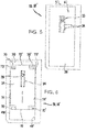
- FIG. 1 A shower area 50 is shown schematically in a separate representation in a ground-level version (without side walls), comprising a wall element 11 and a shower plate 49, which is provided at the factory with a channel 51 and drain installation elements (not shown) for a line drainage known per se.
- the wall element 11 ending in a cover box 16 and the shower tray 49 can be covered, for example, with ceramic or plastic coverings.
- the cover box 16 can have an overall width which is smaller than that of the wall element 11, so that it fits into a rectangular recess on the lower edge of the wall element 11. Another embodiment provides that the total width of the cover box 16 and the wall element 11 is the same.
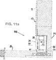
- the Figures 11a and 11b show a superstructure construction 100, comprising the cover box 16 built into the wall element 11 with a cover flap 20 suspended there.
- the superstructure construction 100 covers a schematically indicated drain 10 and at the same time the channel 51.
- the Fig. 1 a projection 52, shown with dashed lines, of the wall element 11 onto the shower tray 49 can be seen.
- the superstructure construction 100 makes it possible to dispense with the grate elements in the step area.
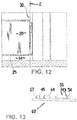
- the elements of the superstructure 100 are also shown in Figures 2a and 2b to see.
- the execution according to Figure 2a differs from the execution according to Figure 2b essentially through the structural design of the locking means with which the position of the cover flap is fixed in relation to the cover box.
- a flexible latching element 33 is provided, which latches into a receiving opening 36 in a predefined pivot position of the suspended cover flap 20 relative to the cover box 16.
- a rigid locking element 33 ' is provided in the form of a projection, which is also in a predefined pivot position the cover flap 20 is fixed in relation to the cover box 16. The fixation takes place in that the locking element 33 'snaps into the receiving opening 36'.
- Both cover boxes 16 are composed of a metal rear wall 17, a metal top wall 19 and two side walls 18, 18 'arranged mirror-symmetrically to one another.
- a cover box made entirely or partially from plastic, in particular injection molded plastic can also be provided.
- the cover box 16 has an underside 12 open towards the drain 10 (cf. Fig. 1 ) and a front side 13 open to the interior of the shower space 50 for receiving said cover flap 20 (cf. Figures 11a , 11b ) on.
- the side wall 18, 18 ' is the Figures 5 to 9 refer to.
- the side wall 18, 18 ' comprises a solid support body 53 made of thermoplastic material, on the inside 69 of which there is a rectangular recess 39 and a guide groove 34 for receiving a nut 38 displaceably arranged there (cf. Fig. 9 ) is introduced.
- the guide groove 34 is approximately T-shaped in cross section.
- the recess 39 of the support body 53 is delimited by two guide edges 48, 48 'so that it forms a guide for a plate-shaped guide element 31 placed there and displaceable along the guide groove 34.
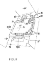
- the guide element 31 comprises two longitudinal edges 71, 71 'and two narrow edges 72, 72', the narrow edges 72, 72 'each via two U-shaped recesses 73, 73' made on the longitudinal edges 71, 71 'in two bent gripping arms 70, 70 'pass.
- the guide element 31 comprising the bore 29 and gripping arms 70, 70 ′ forms a first guide slide 41.
- the described guide element 32 functions as a second guide slide 42, the elongated hole 35 of which is directed perpendicular to the rear wall 17 of the cover box 16 in the assembled state of all guide elements.
- the offset arrangement of the elongated hole 35 with the guide groove 34 resembles a right-angled coordinate system (cf. Figures 6 and 8th ), in which "X” denotes a direction perpendicular to the rear wall 17 and "Y” denotes a direction perpendicular to the top wall 19.
- the interlocking guide elements 31; 32 (or guide carriage 41; 42) and the guide groove 34 ensure that the position of the suspended and aligned cover flap 20 can be adjusted and fixed by tightening the setting element 28 (head screw).
- the cover flap 20 is strip-shaped or cuboid (cf. Figures 2 and 3 ) and is mirror-symmetrical in relation to an in Figures 2a and 2b line of symmetry marked "S".
- the Figures 2a and 2b also shows a plate element 15 of the cover flap 20, having two longitudinal sides 22, 22 'and two narrow sides 23, 23'.
- the cover flap 20 is surrounded by a trough-shaped, metal frame 21.
- the trough-shaped structure enables an insert, for example in the form of natural stone or tiles, to be inserted into the interior of the trough.
- a metal frame 21 made of stainless steel, a first visible surface 24 formed by tiles or natural stone and a second visible surface 24 'formed from the rear of the metal frame 21 and opposite the first visible surface 24 (cf. Figure 11a ).
- the cover flap 20 has on its two narrow sides 23, 23 'elements protruding beyond the frame 21, namely the lower latching element 33 that can be snapped into a receiving opening 36 of the second guide carriage 42, an upper hanging element 64 (support bolt), which in turn is attached to the U-shaped bearing 65 is supported and is arranged to pivot about the axis of rotation 27 to a limited extent.
- the stop element 45 located above the upper latching element 64 also protrudes over the narrow side 23, 23 ′ and contacts the stop surface 46 when the cover flap 20 is aligned and thus limits the rotational movement of the cover flap 20 in direction D2.
- the latching element 33, the stop element 45 and the suspension element 64 designed as a support bolt are integrated into a molded piece 62 which is in Fig. 13 is shown.
- the molded piece 62 is preferably made of plastic and is built into the narrow side 23, 23 'of the cover flap 20 in a form-fitting manner (cf. Fig. 4 ).
- the cover flap 20 is also constructed symmetrically with respect to a center plane M, so that the two visible surfaces 24 and 24 'in the same distance from the central plane M. This makes it easier to turn the cover flap 20 and to change the visible surface 24 or 24 '.
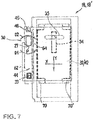
- the suspension element 64 protruding over the narrow side 23, 23 'of the cover flap 20, together with the U-shaped bearing 65, forms a suspension 30 (cf. Fig. 7 ), which according to Fig. 12 lie in the plane E running perpendicular to the rear wall 17 and / or top wall 19 of the cover box 16.
- the U-shaped bearing 65 is preferably rounded and adapted to the contour of the support bolt, which is preferably also rounded in the contact area. The at least approximately round support bolt contour can be rotated in the bearing 65 with little resistance.
- the cover flap 20 is oriented vertically with its ceramic visible surface 24, so that the first visible surface 24 points outward in the direction R1.
- the stop element 45 makes contact with the stop surface 46 of the second guide carriage 42 and prevents a direction of rotation D2 (cf. Fig. 7 ), so that the support bolt (suspension element 64) sits stably in the bearing 65. This corresponds to a first installation position P1 of the cover flap 20.
- the second visible surface 24 'facing inward in the direction R2 is "hidden" from the user in the installation position P1.
- a drain slot 14 is located between a lower edge 25 of the cover flap 20 and a floor surface 26 of the shower tray 49.
- the ceramic visible surface 24 is aligned with a ceramic surface 47 of the wall element 11.
- the cover flap 20 must first be removed. Since the side walls 18, 18 'are also constructed mirror-symmetrically to one another, changing the visible surfaces 24, 24' is very easy.
- the cover flap 20 is manually raised in the area of its lower edge 25, by a maximum of a small amount B (cf. Fig. 4 ) pressed. Since the lower, resilient latching element 33 has an inclined surface section 43 and a flexible projection 54, it yields during this movement, latches out of the receiving opening 36 and slides over an inner surface 44 of the guide carriage 42. Since the stop surface 46 rotates in the direction of rotation D1 allows, the cover flap 20 can be rotated about the axis of rotation 27 by a sufficient angular range. The lower edge 25 of the cover flap 20 pivots into an interior 66 of the cover box 20 and the cover flap 20 can be removed. Depending on the structural design of the latching and suspension elements, it may also be necessary that the rotary movement of the cover flap 20 is carried out in the first step and the cover flap 20 is then lifted out of the mounting in the second step.
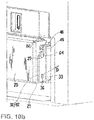
- the removed cover flap 20 is now with its two ends 63, 63 '( Fig. 2, Fig. 2b ) and then reinserted until the lower latching element 33 with its flexible projection 54 - slides over the inner surface 44 of the guide carriage 42 - latches into the receiving opening 36 and the stop element 45 abuts against the stop surface 46.
- This position of the cover flap 20 corresponds to a second installation position P2 (cf. Figures 10a , 10b and 11b ). It should be pointed out that the rotation of the lower locking element 33 about the axis of rotation 27 when engaging and disengaging with a predefined torque D ( Figure 10b ) should take place.
- the suspension 30 must be shifted accordingly by loosening an adjusting element 28.
- a screw 37 is inserted through the elongated hole 35 of the second guide slide 42, the bore 29 of the first guide slide 41 and the guide groove 34 into the nut 38.
- the adjustment element 28 screw 37 with nut 38
- the adjustment element 28 is tightened until the guide carriage 41; 42 with the support body 53 a clamping connection 40 (cf. Fig. 9 ) train.
Landscapes
- Health & Medical Sciences (AREA)
- Public Health (AREA)
- Epidemiology (AREA)
- General Health & Medical Sciences (AREA)
- Life Sciences & Earth Sciences (AREA)
- Engineering & Computer Science (AREA)
- Hydrology & Water Resources (AREA)
- Water Supply & Treatment (AREA)
- Bathtubs, Showers, And Their Attachments (AREA)
- Finishing Walls (AREA)
Description
- Die Erfindung betrifft eine Überbaukonstruktion eines im Bodenbereich eines Wasch- oder Duschplatzes liegenden Ablaufs, welche in ein Wandelement eingebaut oder einzubauen ist, umfassend:
- eine plattenförmige Abdeckklappe,
- einen über den Ablauf zu setzenden Abdeckkasten mit einer vorzugsweise geschlossenen Rückwand, einer Deckenwand und diese verbindenden Seitenwänden, wobei der Abdeckkasten eine zum Ablauf hin offene Unterseite und eine zum Inneren des Wasch- oder Duschplatzes offene Vorderseite zur Aufnahme einer plattenförmigen Abdeckklappe aufweist,
- wobei die Abdeckklappe eine erste und eine zweite Sichtfläche aufweist, von welcher die eine im einmontierten Zustand in Richtung (R1) nach außen und die andere in Richtung (R2) nach innen weist,
- wobei die Abdeckklappe eine Unterkante aufweist und im einmontierten Zustand etwa senkrecht zu einer Bodenfläche des Wasch- oder Duschplatzes ausgerichtet und derart angeordnet ist, das unterhalb der Unterkante ein Ablaufschlitz verbleibt,
- wobei Abdeckklappe und Abdeckkasten über eine Aufhängung lösbar aneinander gekoppelt sind und die Abdeckklappe um eine Drehachse beweglich ist.
- Eine Überbaukonstruktion der vorgenannten Art ist aus der
DE 10 2011 051 496 B4 der Anmelderin bekannt. An den Schmalseiten der Abdeckklappe sind auf die Rückwand des Abdeckkastens zeigende Einhängehaken angeordnet, welche weit über die Sichtfläche der Abdeckklappe hinaus ragen, daher weisen sie eine gewisse Elastizität auf, die eine exakte Ausrichtung beeinträchtigen kann. Außerdem liegt der Einhängepunkt hinter dem Schwerpunkt der Abdeckklappe, so dass die Abdeckklappe mit ihrer Unterkante zur nach hinten geneigten Schrägstellung tendiert, in der ihre Sichtfläche nicht mit der umgebenden Wand fluchtet. Die Schrägstellung kann auch zu ungewünschten Maßdifferenzen und Ungenauigkeiten des die Abdeckklappe umlaufenden Spaltes beitragen. - Dadurch, dass die Einhängehaken ins Innere des Abdeckkastens reichen, kann die Abdeckklappe nur mit einer vorbestimmten, beispielsweise metallenen Sichtfläche eingebaut werden. Soll die Abdeckklappe eine zweite, "verborgene", beispielsweise keramische Sichtfläche haben, müssen die Einhängehaken abgeschraubt, umgedreht und erneut einmontiert werden, um die keramische Sichtfläche anstelle der metallenen zum Vorschein zu bringen.
- Die bekannte Überbaukonstruktion hat sich dennoch bewährt, jedoch besteht der Bedarf, der Neigung der einmontierten Abdeckklappe zur Schrägstellung entgegenzuwirken und die wahlweise Nutzung einer der beiden Sichtflächen zu erleichtern. Es ist daher die Aufgabe der Erfindung, eine neuartige Überbaukonstruktion zu konzipieren, bei der die bisher auftretende Schrägstellung der Abdeckklappe mit einfachen technischen Mitteln vermieden werden kann. Außerdem soll ein problemloses Wenden der Abdeckklappe auf gewünschte Sichtseite gewährleistet werden, ohne Werkzeuge benutzen zu müssen.
- Die vorgenannte Aufgabe ist mit einer Überbaukonstruktion mit Merkmalen des Anspruchs 1 gelöst.
- Weitere technisch vorteilhafte Weiterbildungen sind in den Unteransprüchen beschrieben.
- Von großem Vorteil ist, dass vorzugsweise alle über die Schmalseiten der Abdeckklappe vorspringenden Elemente: das Anschlagelement, das tragende Einhängeelement und das Rastelement in einer gleich weit von den Sichtflächen der Abdeckklappe beabstandeten Mittelebene liegen. Vorzugsweise sind das Einhängeelement und/oder das Rastelement spiegelsymmetrisch zu dieser Mittelebene, so dass die Position der Abdeckklappe sich nicht ändert, wenn die Abdeckklappe gewendet wird. Es ändert sich vielmehr lediglich die Sichtfläche der Abdeckklappe in der Form, dass in einer ersten Einbauposition beispielsweise eine Edelstahlfläche nach außen und eine keramische Oberfläche nach innen weist, während in einer zweiten Einbauposition umgekehrt die Edelstahlfläche nach innen und die keramische Oberfläche nach außen weist.
- Das vorzugsweise als Tragbolzen ausgestaltete Einhängeelement bildet zusammen mit einer am Abdeckkasten angeordneten Lagerung eine stabile Aufhängung für die Abdeckklappe. Dabei kann der Tragbolzen kreisrund oder oval sein oder die Form eines abgeflachten Zylinders haben, dessen abgerundete Fläche sich im eingehängten Zustand der Abdeckklappe an einer mulden- bzw. U-förmigen Lagerung des Abdeckkastens abstützt, so dass ein tiefster Punkt der Lagerung eine Drehachse definiert. Gemäß einer anderen Ausführung kann die Drehachse koaxial mit einer Mittelachse des Tragbolzens angeordnet sein.
- Die mit den vorgenannten vorspringenden Elementen der Abdeckklappe zusammenwirkenden Elemente des Abdeckkastens sind vorzugsweise so angeordnet, dass die eingehängte Abdeckklappe in beiden Einbaupositionen vertikal ausgerichtet und fixiert ist und mit der umliegenden Wand fluchtet. Als Einbauposition soll eine vertikal ausgerichtete Lage der Abdeckklappe verstanden werden, bei der eine vorbestimmte Sichtfläche der Abdeckklappe ausgewählt ist. Beispielsweise kann in einer Einbauposition eine metallische Sichtfläche und in einer anderen Einbauposition eine keramische (Fliesen) Sichtfläche zum Vorschein gebracht werden.
- Das über die Schmalseiten der Abdeckklappe ragende Anschlagelement sowie der Tragbolzen können starr oder flexibel sein.
- Vorzugsweise ist am Abdeckkasten eine Anschlagfläche vorgesehen, mit der das Anschlagelement der Abdeckklappe dann kontaktiert, wenn die Abdeckklappe sich in einer vertikalen Position befindet. Der Anschlag verhindert eine Drehbewegung der Abdeckklappe mit ihrer Unterkante nach außen. Eine Drehbewegung der Abdeckklappe mit ihrer Unterkante nach innen, d. h. in einen Innenraum des Abdeckkastens ist möglich. Bei nach innen eingeschwenkter Abdecklappe können beispielsweise Reinigungsarbeiten in der Ablaufrinne durchgeführt werden. Vorzugsweise ist die Halterung zudem so gestaltet, dass sich die Abdeckklappe bei nach innen eingeschwenkter Position bei Bedarf ganz aus der Halterung herausheben bzw. demontieren lässt. Sonst hängt die Abdeckklappe, durch den symmetrischen Aufbau bedingt, in ihrer vertikalen Lage am Abdeckkasten. Dabei ist vorteilhaft, dass die beiden Einhängeelemente (Tragbolzen) oberhalb einer Schwerpunktlinie der Abdeckklappe liegen.
- Die Abdeckplatte kann an ihren Schmalseiten mit in Richtung Seitenwände ragenden Rast- und Anschlagelementen versehen sein, welche zum einen eine Drehung der Abdeckplatte um eine Drehachse ermöglichen und zum anderen ihre vertikale, stabile Ausrichtung sichern, so dass die eingesetzte Abdeckplatte mit einer Oberfläche des Wandelementes, beispielsweise Fliesenbelag in Flucht liegen kann.
- Die über die Schmalseiten der Abdeckplatte ragenden Rastelemente können starr oder flexibel sein. Mittels der Rastelemente kann die Abdeckklappe einerseits sicher in einer gewünschten Position gehalten und andererseits bei Bedarf, z.B. zur Reinigung der im Inneren des Überbauelements angeordneten Ablaufrinne, leicht demontiert werden.
- Ein starres Rastelement kann beispielsweise durch einen starren, aus der Seitenfläche der Abdeckklappe hervorragenden Bolzen ausgebildet sein. Die Rastfunktion wird in diesem Fall realisiert, indem die um die Drehachse der Aufhängung drehbare Abdeckklappe kurz vor Erreichen ihrer vertikalen Endposition eine Ausbuchtung am Rand einer Vertiefung kontaktiert. Wird die Klappe weiter gedreht, wird der Bolzen an der Ausbuchtung entlanggeführt und die Klappe hebt sich insgesamt etwas an. Nach Überwindung der genannten Ausbuchtung rastet der Bolzen schwerkraftbedingt in der hinter der Ausbuchtung liegenden Vertiefung ein.
- Eine flexible Ausführung eines Rastelementes kann realisiert sein, indem der Rastbolzen sich in Richtung Schmalseite gegen ein Federelement abstützt und somit linear beweglich ist. Als Gegenlager kann in der Seitenwand des Abdeckkastens bzw. in einem Führungsschlitten eine Bohrung vorgesehen sein. Bei Drehung der Abdeckklappe um die Drehachse stützt der Außenpunkt des flexiblen Rastbolzens sich solange an der Wandung des Abdeckkastens ab, bis die Position der Bohrung erreicht ist und das Ende des Rastbolzens durch die Federkraft in die Bohrung einrastet. Je nach konstruktiver Ausgestaltung kann entweder das flexible Element an der Abdeckklappe und die Bohrung in der Seitenwand oder umgekehrt das flexible Element in der Seitenwand und die Bohrung in der Abdeckklappe angeordnet sein.
Alternativ zu einem mechanischen Rastelement kann auch eine andere Fixiereinrichtung, beispielsweise ein Magnet, vorgesehen sein. Damit das Rastelement auch dann in die Öffnung einrastet, wenn die Abdeckklappe gewendet wird, ist es vorzugweise ebenfalls in der Mittelebene der Abdeckklappe angeordnet. - Einhängeelement und/oder Rastelement und/oder Anschlagelement können unmittelbar in die Abdeckklappe integriert sein. So können beispielsweise aus dem Material der Abdeckklappe mittels entsprechender Stanzwerkzeuge die genannten Funktionselemente herausgearbeitet werden. Besonders bevorzugt wird jedoch eine Ausführung, bei der die genannten Funktionsteile Einhängeelement, Rastelement und/oder Anschlagelement aus einem Formstuck, insbesondere aus einem Kunststoffteil, hergestellt sind. Dieses Formstücks ist so gestaltet, dass es in die Schmalseite der Abdeckklappe vorzugsweise formschlüssig einbaubar ist. Eine solche Ausführung trägt dazu bei, dass die vorspringenden Elemente mit großer Genauigkeit an entsprechende Aussparungen an den Schmalseiten angepasst sind und außerdem erleichtert es die Serienproduktion der Abdeckklappen.
- Vorzugsweise umfassen die Seitenwände des Abdeckkastens jeweils einen quaderförmigen Tragkörper, an welchem eine Mulde bzw. Vertiefung für Führungselemente der Aufhängung und eine Führungsnut zur Aufnahme einer dort verschiebbar angeordneten Mutter eingebracht sind, in welche ein vorzugsweise schraubenartiges Einstellelement eingedreht ist.
- Der quaderförmige Tragkörper kann aus Metall oder aus Kunststoff hergestellt sein, beispielsweise im Spritzguss- oder 3D-Druck-Fertigungsverfahren. Mit Hilfe des 3D-Druckers lassen sich komplizierte Geometrien in einem Arbeitsgang erzeugen. Als Kunststoff kommen Duro- und Thermoplaste in Frage.
- Die Führungselemente bilden zusammen mit dem Tragkörper und dem Einstellelement eine Klemmvorrichtung zur Fixierung der Abdeckklappe.
- Die Justierbarkeit der Abdeckklappe gegenüber dem Abdeckkasten, dem Wandelement und zugleich der Bodenfläche des Wasch- und Duschplatzes kann durch ineinandergreifende und verschiebbare Führungselemente erfolgen. Befindet sich die Aufhängung in einer vorbestimmten Position, werden die Führungselemente und damit die Aufhängepunkte fixiert. Im Ergebnis kann danach die Abdeckklappe beliebig oft ein- und ausgebaut werden und nimmt dabei im eingehängten Zustand immer wieder dieselbe Position ein.
- Vorzugsweise sind Enden bzw. Schmalseiten der Abdeckklappe sowie ihre Sichtflächen zueinander spiegelsymmetrisch aufgebaut. Ebenso sind Seitenwände des Abdeckkastens mit ihren Führungselementen und Einstellelementen zueinander spiegelsymmetrisch aufgebaut. Dies ermöglicht ein einfaches Wechseln der Sichtfläche durch Umlegen und erneutes Einsetzen der Abdeckklappe in die Aufhängung der Seitenwände.
- Die Erfindung ist in einem Ausführungsbeispiel anhand der Zeichnung näher erläutert. Die Figuren zeigen:
- Fig. 1
- die in ein Wandelement eingebaute Überbaukonstruktion, ohne Aufhängungsdetails, vor dem Verbinden mit einer Bodenplatte eines Duschplatzes, in einer schematischen perspektivischen Ansicht;
- Fig. 2a
- den Abdeckkasten vor dem Einsetzen der Abdeckklappe, in einer perspektivischen Ansicht;
- Fig. 2b
- eine alternative Ausführungsform des Abdeckkastens vor dem Einsetzen der Abdeckklappe in einer perspektivischen Ansicht;
- Fig. 3
- einen Teil der Abdeckklappe mit sichtbaren Anschlag- und Rastelementen, in einer perspektivischen Ansicht;
- Fig. 4
- eine Draufsicht auf eine Schmalseite der Abdeckklappe;
- Fig. 5
- eine als Tragkörper ausgebildete Seitenwand des Abdeckkastens, in Draufsicht auf eine Innenseite des Tragkörpers;
- Fig. 6
- die Seitenwand gemäß
Fig. 5 mit einem Führungsschlitten, in Draufsicht auf die Innenseite des Tragkörpers; - Fig. 7
- die Seitenwand gemäß
Fig. 5 mit zwei ineinander greifenden Führungsschlitten, in Draufsicht auf die Innenseite des Tragkörpers; - Fig. 8
- die am Tragkörper angeordneten Führungsschlitten in zwei Positionen, in einer perspektivischen Ansicht;
- Fig. 9
- eine Klemmverbindung der Führungsschlitten, in einer schematischen Darstellung;
- Fig. 10a
- eine Aufhängung der Abdeckklappe mit abgenommener Seitenwand, in einer perspektivischen Ansicht;
- Fig. 10b
- die Aufhängung gemäß
Fig. 10a , mit Seitenwand, in einer perspektivischen Ansicht; - Figuren 11a und 11b:
- jeweils den Duschplatz gemäß
Fig.1 , mit ausgerichteter Abdeckklappe, welche gemäßFig. 11a mit ihrer keramischen und gemäßFig. 11b mit metallischer Sichtfläche nach aussen weist; - Fig. 12
- die Aufhängung der Abdeckklappe am Abdeckkasten in einer seitlichen schematischen Ansicht;
- Fig. 13
- ein in die Schmalseite der Abdeckklappe einbaubares Formstück mit Anschlag- und Rastelementen, in einer Seitenansicht.
- Gleiche oder ähnliche Elemente können in den nachfolgenden Figuren mit gleichen oder ähnlichen Bezugszeichen versehen sein. Ferner enthalten die Figuren der Zeichnung, deren Beschreibung sowie die Ansprüche zahlreiche Merkmale in Kombination. Einem Fachmann ist dabei klar, dass diese Merkmale auch einzeln betrachtet werden oder sie zu weiteren, hier nicht näher beschriebenen Kombinationen zusammengeführt werden können.
- In
Fig. 1 ist in getrennter Darstellung ein Duschplatz 50 in ebenerdiger Ausführung (ohne Seitenwände) schematisch gezeigt, umfassend ein Wandelement 11 und eine Duschplatte 49, welche werkseitig mit einer Rinne 51 und nicht gezeigten Ablaufinstallationselementen für eine an sich bekannte Linienentwässerung versehen ist. Das in einen Abdeckkasten 16 auslaufende Wandelement 11 sowie die Duschplatte 49 können beispielsweise mit Keramik- oder Kunststoffbelägen bedeckt werden. Der Abdeckkasten 16 kann eine Gesamtbreite haben, die kleiner ist als die des Wandelementes 11, so dass er in eine rechteckige Aussparung an der unteren Kante des Wandelementes 11 hineinpasst. Eine andere Ausführung sieht vor, dass die Gesamtbreite des Abdeckkastens 16 und des Wandelementes 11 gleich ist. - Die
Figuren 11a und11b zeigen eine Überbaukonstruktion 100, umfassend den in das Wandelement 11 eingebauten Abdeckkasten 16 mit einer dort eingehängten Abdeckklappe 20. Die Überbaukonstruktion 100 deckt einen schematisch angedeuteten Ablauf 10 und zugleich die Rinne 51 ab. DerFig. 1 ist eine mit Strichlinien gezeigte Projektion 52 des Wandelementes 11 auf die Duschplatte 49 zu entnehmen. Die Überbaukonstruktion 100 erlaubt es, auf die Rostelemente im Trittbereich zu verzichten. - Die Elemente der Überbaukonstruktion 100 sind auch in
Fig. 2a und 2b zu sehen. Die Ausführung gemäßFigur 2a unterscheidet sich von der Ausführung gemäßFigur 2b im Wesentlichen durch die konstruktive Ausgestaltung der Rastmittel, mit denen die Position der Abdeckklappe gegenüber dem Abdeckkasten fixiert wird. InFig. 2a ist zu diesem Zweck ein flexibles Rastelement 33 vorgesehen, welches in einer vordefinierten Schwenkposition der eingehängten Abdeckklappe 20 gegenüber dem Abdeckkasten 16 in eine Aufnahmeöffnung 36 einrastet. InFig. 2b ist ein starres Rastelement 33' in Form eines Vorsprungs vorgesehen, welcher ebenfalls in einer vordefinierten Schwenkposition die Abdeckklappe 20 gegenüber dem Abdeckkasten 16 fixiert. Die Fixierung erfolgt indem das Rastelement 33' in die Aufnahmeöffnung 36' einrastet. - Beide Abdeckkasten 16 setzen sich aus einer metallenen Rückwand 17, einer metallenen Deckenwand 19 und zwei zueinander spiegelsymmetrisch angeordneten Seitenwänden 18, 18' zusammen. Alternativ zu einer metallen Ausführung kann auch ein ganz oder teilweise aus Kunststoff, insbesondere Spritzgusskunststoff, hergestellter Abdeckkasten vorgesehen sein. Der Abdeckkasten 16 weist eine zum Ablauf 10 hin offene Unterseite 12 (vgl.
Fig. 1 ) und eine zum Inneren des Duschplatzes 50 offene Vorderseite 13 zur Aufnahme der besagten Abdeckklappe 20 (vgl.Figuren 11a ,11b ) auf. - Der Aufbau der Seitenwand 18, 18' ist den
Figuren 5 bis 9 zu entnehmen. Im dargestellten Ausführungsbeispiel umfasst die Seitenwand 18, 18' einen aus thermoplastischem Kunststoff hergestellten, massiven Tragkörper 53, auf dessen Innenseite 69 eine rechteckige Vertiefung 39 und eine Führungsnut 34 zur Aufnahme einer dort verschiebbar angeordneten Mutter 38 (vgl.Fig. 9 ) eingebracht ist. Wie insbesondere dieFig. 9 zeigt, ist die Führungsnut 34 in ihrem Querschnitt etwa T-förmig. - Die Vertiefung 39 des Tragkörpers 53 ist durch zwei Führungskanten 48, 48' begrenzt, so dass sie eine Führung für ein dort platziertes, entlang der Führungsnut 34 verschiebbares, plattenförmiges Führungselement 31 ausbildet. An dem Führungselement 31 ist eine mit der Führungsnut 34 koinzidierende Bohrung 29 zur Durchführung einer Schraube 37 (Kopfschraube; vgl.
Figuren 2 und9 ) eingebracht. Das Führungselement 31 umfasst zwei Längskanten 71, 71' und zwei Schmalkanten 72, 72', wobei die Schmalkanten 72, 72' jeweils über zwei an den Längskanten 71, 71' eingebrachte U-förmige Aussparungen 73, 73' in zwei abgebogene Greifarme 70, 70' übergehen. Das die Bohrung 29 und Greifarme 70, 70' umfassende Führungselement 31 bildet einen ersten Führungsschlitten 41 aus. - Die Greifarme 70, 70' umgreifen ein zweites Führungselement 32 (vgl.
Figuren 7 und8 ) an dessen kürzeren Seiten und bilden dadurch eine Führung für das zweite Führungselement 32. - Das zweite Führungselement 32 (vgl.
Figuren 7 bis 9 ) hat einen rechteckigen Umriss und weist folgende Einzelheiten auf: - ein Langloch 35, welches im einmontierten Zustand gegenüber der am Tragkörper 53 eingebrachten Führungsnut 34 um 90° versetzt ist;
- eine Anschlagfläche 46 für ein Anschlagelement 45 (vgl.
Figuren 3 und 4 ) der Abdeckklappe 20; - eine Aufnahmeöffnung 36 für ein federndes Rastelement 33 (vgl.
Figuren 3 und 4 ) der Abdeckklappe 20; - eine U-förmige, etwas von der Anschlagfläche 46 zurückversetzte Lagerung 65 für einen über die Schmalseite 23, 23' der Abdeckklappe 20 ragenden Tragbolzen 64; Der tiefste Punkt P der Lagerung 65 definiert eine Drehachse 27 der Abdeckklappe 20.
- Das beschriebene Führungselement 32 fungiert zu einem zweiten Führungsschlitten 42, dessen Langloch 35 im zusammengesetzten Zustand aller Führungselemente senkrecht zur Rückwand 17 des Abdeckkastens 16 gerichtet ist.
- Die versetzte Anordnung des Langlochs 35 mit der Führungsnut 34 ähnelt einem rechtwinkligen Koordinatensystem (vgl.
Figuren 6 und8 ), bei dem mit "X" eine Richtung senkrecht zur Rückwand 17 und "Y" eine Richtung senkrecht zur Deckenwand 19 bezeichnet ist. Die ineinander greifenden Führungselemente 31; 32 (bzw. Führungsschlitten 41; 42) und die Führungsnut 34 sorgen dafür, dass die Lage der eingehängten und ausgerichteten Abdeckklappe 20 justiert und durch Anziehen des Einstellelementes 28 (Kopfschraube) fixiert werden kann. - Die Abdeckklappe 20 ist leisten- bzw. quaderförmig (vgl.
Figuren 2 und3 ) und ist spiegelsymmetrisch aufgebaut in Bezug auf eine inFig. 2a und 2b mit "S" bezeichnete Symmetrielinie. DieFig. 2a und 2b zeigt auch ein Plattenelement 15 der Abdeckklappe 20, aufweisend zwei Längsseiten 22, 22' und zwei Schmalseiten 23, 23'. GemäßFig. 4 ist die Abdeckklappe 20 von einen trogförmigen, metallenen Rahmen 21 umgeben. Der trogförmige Aufbau ermöglicht es, in das Innere des Troges einen Einsatz, beispielsweise in Form von Naturstein oder Fliesen, einzusetzen. Bei einem aus Edelstahl ausgebildeten Metallrahmen 21 ergibt sich so eine erste, von Fliesen oder Naturstein gebildete Sichtfläche 24 und eine aus der Rückseite des Metallrahmens 21 gebildete, der ersten Sichtfläche 24 gegenüber liegende, zweite Sichtfläche 24' (vgl.Fig. 11a ). - Weiterhin weist die Abdeckklappe 20 auf ihren beiden Schmalseiten 23, 23' über den Rahmen 21 ragende Elemente auf, nämlich das untere, in eine Aufnahmeöffnung 36 des zweiten Führungsschlittens 42 einrastbares Rastelement 33, ein oberes Einhängeelement 64 (Tragbolzen), welches sich wiederum an der U-förmigen Lagerung 65 abstützt und um die Drehachse 27 begrenzt schwenkbar angeordnet ist. Über die Schmalseite 23, 23' ragt auch das oberhalb des oberen Rastelementes 64 befindliches Anschlagelement 45, welches bei der ausgerichteten Abdeckklappe 20 mit der Anschlagfläche 46 kontaktiert und so die Drehbewegung der Abdeckklappe 20 in Richtung D2 begrenzt.
- Im dargestellten Ausführungsbeispiel sind die das Rastelement 33, das Anschlagelement 45 und das als Tragbolzen ausgeführte Einhängeelement 64 in ein Formstück 62 integriert, welches in
Fig. 13 dargestellt ist. Das Formstück 62 besteht vorzugsweise aus Kunststoff und ist in die Schmalseite 23, 23' der Abdeckklappe 20 formschlüssig eingebaut (vgl.Fig. 4 ). - Wie insbesondere die
Fig. 4 zeigt, ist die Abdeckklappe 20 auch in Bezug auf eine Mittelebene M symmetrisch aufgebaut, so dass die beiden Sichtflächen 24 und 24' im gleichen Abstand von der Mittelebene M liegen. Dies erleichtert das Drehen der Abdeckklappe 20 und das Wechseln der Sichtfläche 24 bzw. 24'. - Das über die Schmalseite 23, 23' der Abdeckklappe 20 ragende Einhängeelement 64 (Tragbolzen) bildet zusammen mit der U-förmigen Lagerung 65 eine Aufhängung 30 (vgl.
Fig. 7 ), welche gemäßFig. 12 in der senkrecht zur Rückwand 17 und/oder Deckenwand 19 des Abdeckkastens 16 verlaufenden Ebene E liegen. Die U-förmige Lagerung 65 ist vorzugsweise abgerundet und an die Kontur des Tragbolzens, der im Kontaktbereich vorzugsweise ebenfalls abgerundet ist, angepasst. Die zumindest in etwa runde Tragbolzenkontur ist so widerstandsarm in der Lagerung 65 drehbar. - Wie der
Fig. 11a zu entnehmen ist, ist die Abdeckklappe 20 mit ihrer keramischen Sichtfläche 24 vertikal ausgerichtet, so dass die erste Sichtfläche 24 in Richtung R1 nach außen weist. Das Anschlagelement 45 kontaktiert mit der Anschlagfläche 46 des zweiten Führungsschlittens 42 und verhindert eine Drehrichtung D2 (vgl.Fig. 7 ), so dass der Tragbolzen (Einhängeelement 64) stabil in der Lagerung 65 sitzt. Dies entspricht einer ersten Einbauposition P1 der Abdeckklappe 20. - Die zweite, in Richtung R2 nach innen zeigende Sichtfläche 24' ist in Einbauposition P1 für den Benutzer "verborgen". Zwischen einer Unterkante 25 der Abdeckklappe 20 und einer Bodenfläche 26 der Duschplatte 49 befindet sich ein Ablaufschlitz 14. Die keramische Sichtfläche 24 fluchtet mit einer keramischen Oberfläche 47 des Wandelementes 11.
- Wird die andere, metallische Sichtfläche 24' als nach außen weisende Sichtfläche gewünscht, muss die Abdeckklappe 20 zuerst ausgebaut werden. Da die Seitenwände 18, 18' ebenso zueinander spiegelsymmetrisch aufgebaut sind, ist das Wechseln der Sichtflächen 24, 24' sehr einfach.
- Um dies zu verwirklichen, wird die Abdeckklappe 20 im Bereich ihrer Unterkante 25 manuell nach oben, maximal um einen kleinen Betrag B (vgl.
Fig. 4 ) gedrückt. Da das untere, federnde Rastelement 33 einen schrägen Flächenabschnitt 43 und einen flexiblen Vorsprung 54 aufweist, gibt es bei dieser Bewegung nach, rastet aus der Aufnahmeöffnung 36 aus und gleitet über eine Innenfläche 44 des Führungsschlittens 42. Da die Anschlagfläche 46 eine Drehbewegung in Drehrichtung D1 zulässt, kann die Abdeckklappe 20 um die Drehachse 27 um einen ausreichenden Winkelbereich gedreht werden. Dabei schwenkt die Unterkante 25 der Abdeckklappe 20 in einen Innenraum 66 des Abdeckkastens 20 ein und die Abdeckklappe 20 kann herausgenommen werden. Je nach konstruktiver Ausgestaltung der Rast- und Aufhängeelemente kann es auch erforderlich sein, dass im ersten Schritt die Drehbewegung der Abdeckklappe 20 durchgeführt wird und die Abdeckklappe 20 dann im zweiten Schritt aus der Lagerung herausgehoben wird. - Die herausgenommene Abdeckklappe 20 wird jetzt mit ihren beiden Enden 63, 63' (
Fig. 2, Fig. 2b ) gewendet und danach erneut eingesetzt bis das untere Rastelement 33 mit seinem flexiblen Vorsprung 54 - über die Innenfläche 44 des Führungsschlittens 42 gleitend - in die Aufnahmeöffnung 36 einrastet und das Anschlagelement 45 gegen die Anschlagfläche 46 stößt. Diese Lage der Abdeckklappe 20 entspricht einer zweiten Einbauposition P2 (vgl.Figuren 10a ,10b und11b ). Es sei darauf hingewiesen, dass die Drehung des unteren Rastelementes 33 um die Drehachse 27 beim Ein- und Ausrasten mit einem das Rastelement 33 schonenden, vordefinierten Drehmoment D (Fig. 10b ) erfolgen soll. - Soll die Lage der Abdeckklappe 20 gegenüber dem Abdeckkasten 16 insgesamt korrigiert werden, muss die Aufhängung 30 durch das Lösen eines Einstellelementes 28 entsprechend verschoben werden. Eine Schraube 37 ist durch das Langloch 35 des zweiten Führungsschlittens 42, die Bohrung 29 des ersten Führungsschlittens 41 und die Führungsnut 34 in die Mutter 38 eingeführt. Nach durchgeführter Justierung wird das Einstellelement 28 (Schraube 37 mit Mutter 38) angezogen bis die Führungsschlitten 41; 42 mit dem Tragkörper 53 eine Klemmverbindung 40 (vgl.
Fig. 9 ) ausbilden.Bezugszeichenliste: 10 Ablauf 35 Langloch (v. 32) 11 Wandelement 36, 36' Aufnahmeöffnung 12 Unterseite 37 Schraube 13 Vorderseite 38 Mutter 14 Ablaufschlitz 39 Vertiefung 15 Plattenelement 40 Klemmverbindung 16 Abdeckkasten 41 erster Führungsschlitten 17 Rückwand 42 zweiter Führungsschlitten 18, 18' Seitenwand 43 schräger Flächenabschnitt (v. 33) 19 Deckenwand 44 Innenfläche (v. 42) 20 Abdeckklappe 45 Anschlagelement (an der 21 Rahmen Abdeckklappe 20) 22, 22' Längsseite (v. 20) 46 Anschlagfläche 23, 23' Schmalseite (v. 20) (am Abdeckkasten 16) 24 erste Sichtfläche 47 Oberfläche 24' zweite Sichtfläche 48, 48' Führungskante ( Fig. 6 )25 Unterkante 49 Duschplatte 26 Bodenfläche 50 Duschplatz 27 Drehachse 51 Rinne 28 Einstellelement 52 Projektion 29 Bohrung 53 Tragkörper (v. 18) 30 Aufhängung 54 Vorsprung (v. 33) 31 erstes Führungselement 55 - 32 zweites Führungselement 33, 33' Rastelement 62 Formstück 34 Führungsnut 63, 63' Ende (v. 20) 64 Einhängeelement (Tragbolzen) 65 Lagerung 66 Innenraum 67, 67' Anschlagfläche 68 - 69 Innenseite 70, 70' Greifarm 71, 71' Längskante (v. 39) 72, 72' Schmalkante (v. 39) 73, 73' Aussparung (v. 39) 100, 100' Überbaukonstruktion D Drehmoment D1,D2 Drehrichtung B Betrag E Ebene M Mittelebene X, Y Richtung P Punkt (der Lagerung 65) P1, P2 Einbauposition R1, R2 Richtung S Symmetrielinie
Claims (11)
- Überbaukonstruktion (100; 100') eines im Bodenbereich eines Wasch- oder Duschplatzes liegenden Ablaufs (10), welche in ein Wandelement (11) eingebaut oder einzubauen ist, umfassend:- eine plattenförmige Abdeckklappe (20),- einen über den Ablauf (10) zu setzenden Abdeckkasten (16) mit einer Rückwand (17), einer Deckenwand (19) und diese verbindenden Seitenwänden (18, 18'), wobei der Abdeckkasten (16) eine zum Ablauf (10) hin offene Unterseite (12) und eine zum Inneren des Wasch- oder Duschplatzes offene Vorderseite (13) zur Aufnahme der plattenförmigen Abdeckklappe (20) aufweist,- wobei die Abdeckklappe (20) eine erste und eine zweite Sichtfläche (24; 24') aufweist, von welcher die eine im einmontierten Zustand in Richtung (R1) nach außen und die andere in Richtung (R2) nach innen weist,- wobei die Abdeckklappe (20) eine Unterkante (25) aufweist und im einmontierten Zustand etwa senkrecht zu einer Bodenfläche (26) des Wasch- oder Duschplatzes ausgerichtet und derart angeordnet ist, dass unterhalb der Unterkante (25) ein Ablaufschlitz (14) verbleibt,- wobei Abdeckklappe (20) und Abdeckkasten (16) über eine Aufhängung (30) lösbar aneinander gekoppelt sind und die Abdeckklappe (20) um eine Drehachse (27) beweglich ist,dadurch gekennzeichnet, dass- an der Abdeckklappe (20) oder am Abdeckkasten (16) ein Rastelement (33; 33') angeordnet ist, mit welchem die Abdeckklappe (20) in ersten Einbauposition (P1) oder in einer zweiten Einbauposition (P2) in vorzugsweise senkrechter Ausrichtung fixierbar ist,- die Drehachse (27) und ein um die Drehachse (27) drehbares Einhängeelement (64) sowie das im einmontierten Zustand der Abdeckklappe (20) unterhalb der Drehachse (27) liegende Rastelement (33; 33') jeweils gleich weit von der ersten Sichtfläche (24) und der zweiten Sichtfläche (24') beabstandet sind, so dass in der ersten Einbauposition (P1) der Abdeckklappe (20) die erste Sichtfläche (24) in Richtung (R1) weist und in der zweiten Einbauposition (P2) die zweite Sichtfläche (24') in Richtung (R1) weist.
- Überbaukonstruktion nach Anspruch 1, dadurch gekennzeichnet, dass die Lage der Drehachse (27) durch einen tiefsten Punkt (P) einer am Abdeckkasten (16) angeordneten U-förmigen Lagerung (65) des Einhängeelements (64) definiert ist.
- Überbaukonstruktion nach Anspruch 1 oder 2, dadurch gekennzeichnet, dass die Aufhängung (30) ein über eine Schmalseite (23, 23') der Abdeckklappe (20) vorspringendes Einhängeelement (64) und eine Lagerung (65) für das Einhängeelement (64) umfasst.
- Überbaukonstruktion nach einem der Ansprüche 1 bis 3, dadurch gekennzeichnet, dass oberhalb des Einhängeelementes (64) der Abdeckklappe (20) ein Anschlagelement (45) mit Anschlagflächen (67, 67') angeordnet ist, welche gleich weit von der ersten Sichtfläche (24) und der zweiten Sichtfläche (24') beabstandet sind und wobei die Anschlagfläche (67, 67') im ausgerichteten Zustand der Abdeckklappe (20) mit einer Anschlagfläche (46) des Abdeckkastens (16) kontaktiert, so dass die Drehbewegung der Abdeckklappe (20) um die Drehachse (27) begrenzt ist.
- Überbaukonstruktion nach einem der Ansprüche 1 bis 4, dadurch gekennzeichnet, dass die Abdeckklappe (20) eine Mittelebene (M) aufweist und das Einhängeelement (64) und/oder das Rastelement (33; 33') und/oder das Anschlagelement (45) zur Mittelebene (M) eine spiegelsymmetrische Kontur aufweist.
- Überbaukonstruktion nach einem der Ansprüche 1 bis 5, dadurch gekennzeichnet, dass das Einhängeelement (64) an der Abdeckklappe (20) und die Lagerung (65) am Abdeckkasten (16) angeordnet ist.
- Überbaukonstruktion nach einem der Ansprüche 1 bis 6, dadurch gekennzeichnet, dass das Rastelement (33) einen flexiblen Vorsprung (43) umfasst, welcher bei Drehung der Abdeckklappe (20) um die Drehachse (27) in eine Aufnahmeöffnung (36) einrastet.
- Überbaukonstruktion nach einem der Ansprüche 1 bis 6, dadurch gekennzeichnet, dass das Rastelement (33') einen starren Vorsprung umfasst, welcher bei Drehung der Abdeckklappe (20) um die Drehachse (27) in eine Aufnahmeöffnung (36') einrastet
- Überbaukonstruktion nach einem der Ansprüche 1 bis 8, dadurch gekennzeichnet, dass das Rastelement (33; 33') bei einem vordefinierten Drehmoment (D) um die Drehachse (27) einrastet und/oder ausrastet.
- Überbaukonstruktion nach einem der Ansprüche 1 bis 9, dadurch gekennzeichnet, dass das Einhängeelement (64), das Rastelement (33; 33') und das Anschlagelement (45) der Abdeckklappe (20) Teile eines Formstücks (62) sind, welches in die Schmalseite (23, 23') vorzugsweise formschlüssig eingebaut ist.
- Überbaukonstruktion nach einem der Ansprüche 1 bis 10, dadurch gekennzeichnet, dass- an den Seitenwänden (18, 18') des Abdeckkastens (16) oder an den Schmalseiten (23, 23') der Abdeckklappe (20), zueinander kompatible Führungselemente (31; 32) vorgesehen sind, welche jeweils in einer senkrecht zur Rückwand (17) bzw. Deckenwand (19) verlaufenden Ebene (E) angeordnet und mit einem Einstellelement (28) an dem Abdeckkasten (16) oder an der Abdeckklappe (20) fixierbar sind,- die Aufhängung (30) über ein erstes Führungselement (31) in einer Richtung (Y) senkrecht zur Deckenwand (19) und über ein zweites Führungselement (32) in einer Richtung (X) senkrecht zur Rückwand (17) verschiebbar ist,so dass die Position der Abdeckklappe (20) gegenüber dem Abdeckkasten (16) sowohl hinsichtlich ihres Abstandes zur Deckenwand (19) als auch hinsichtlich ihres Abstandes zur Rückwand (17) vordefinierbar und mit dem Einstellelement (28) fixierbar ist.
Applications Claiming Priority (1)
| Application Number | Priority Date | Filing Date | Title |
|---|---|---|---|
| DE102018104794.0A DE102018104794A1 (de) | 2018-03-02 | 2018-03-02 | Überbaukonstruktion für einen Wasserablauf mit symmetrischer Abdeckklappen-Aufhängung |
Publications (2)
| Publication Number | Publication Date |
|---|---|
| EP3533367A1 EP3533367A1 (de) | 2019-09-04 |
| EP3533367B1 true EP3533367B1 (de) | 2020-12-16 |
Family
ID=65529521
Family Applications (1)
| Application Number | Title | Priority Date | Filing Date |
|---|---|---|---|
| EP19158809.4A Active EP3533367B1 (de) | 2018-03-02 | 2019-02-22 | Überbaukonstruktion für einen wasserablauf mit symmetrischer abdeckklappen-aufhängung |
Country Status (2)
| Country | Link |
|---|---|
| EP (1) | EP3533367B1 (de) |
| DE (1) | DE102018104794A1 (de) |
Family Cites Families (5)
| Publication number | Priority date | Publication date | Assignee | Title |
|---|---|---|---|---|
| FR2916458B1 (fr) * | 2007-05-25 | 2009-08-07 | Constru Sa | Bouche d'egout avec un puits equipe d'un porte-filtre et d'un filtre amovible |
| DE202011002821U1 (de) * | 2011-02-16 | 2012-02-23 | Mepa - Pauli Und Menden Gmbh | Duschwanne mit integriertem Wandablauf |
| DE102011051496B4 (de) | 2011-07-01 | 2013-04-04 | Stephan Wedi | Überbausystem für einen im Bodenbereich befindlichen Ablauf |
| EP2818600B1 (de) * | 2013-06-26 | 2017-04-19 | Geberit International AG | Bodeneinlauf mit justierbarer Blende |
| DE202014004016U1 (de) * | 2014-05-12 | 2014-08-14 | Frank Huster | Revisionsklappe mit magnetischer Positionierungshilfe |
-
2018
- 2018-03-02 DE DE102018104794.0A patent/DE102018104794A1/de not_active Ceased
-
2019
- 2019-02-22 EP EP19158809.4A patent/EP3533367B1/de active Active
Also Published As
| Publication number | Publication date |
|---|---|
| DE102018104794A1 (de) | 2019-09-05 |
| EP3533367A1 (de) | 2019-09-04 |
Similar Documents
| Publication | Publication Date | Title |
|---|---|---|
| DE2911094A1 (de) | Plattenverbindungssystem | |
| EP2808457A2 (de) | Wasserablaufvorrichtung für eine sanitäre Anlage, wie einen bodenebenen Duschplatz | |
| EP2540922A2 (de) | Überbausystem für einen im Bodenbereich befindlichen Ablauf | |
| DE102007057382B4 (de) | Nivellierfuß | |
| AT398516B (de) | Schubkastenauszug | |
| EP3486420A2 (de) | Vorrichtung zum positionieren eines fensters oder einer tür | |
| EP2159345B1 (de) | Halterung für Verkleidungselemente | |
| EP2618706B1 (de) | Duschwand mit einer schiebetür | |
| EP3167988B1 (de) | Lochsäge | |
| EP0495205B1 (de) | Trennwand für Dusche mit verschwenkbarer Türe | |
| EP4216763A1 (de) | Möbelelement und möbel | |
| DE2253600A1 (de) | Stange zum einfuehren von vorhangtraegern | |
| AT515689B1 (de) | Schublade | |
| EP3533367B1 (de) | Überbaukonstruktion für einen wasserablauf mit symmetrischer abdeckklappen-aufhängung | |
| DE102018122142B4 (de) | Klemmaufnahme und Bandtasche | |
| EP2880226B1 (de) | KIPPBARE FUßBODENPROFILANORDNUNG | |
| EP3533944B1 (de) | Überbaukonstruktion für einen wasserablauf mit justierbarer abdeckklappen-aufhängung | |
| AT519907B1 (de) | Möbelscharnier | |
| EP2208843B1 (de) | Scharnier für eine Tür | |
| DE19828233A1 (de) | Wandkonsole | |
| EP2818600B1 (de) | Bodeneinlauf mit justierbarer Blende | |
| DE4000456A1 (de) | Fraes- oder bohrvorrichtung | |
| DE2209532A1 (de) | Stange zum einfuehren von vorhangtraegern | |
| WO1997048087A1 (de) | Halter für wendetafeln od. dgl. | |
| DE9105450U1 (de) | Verstellbare Stützvorrichtung für eine Schubkastenfront |
Legal Events
| Date | Code | Title | Description |
|---|---|---|---|
| PUAI | Public reference made under article 153(3) epc to a published international application that has entered the european phase |
Free format text: ORIGINAL CODE: 0009012 |
|
| STAA | Information on the status of an ep patent application or granted ep patent |
Free format text: STATUS: THE APPLICATION HAS BEEN PUBLISHED |
|
| AK | Designated contracting states |
Kind code of ref document: A1 Designated state(s): AL AT BE BG CH CY CZ DE DK EE ES FI FR GB GR HR HU IE IS IT LI LT LU LV MC MK MT NL NO PL PT RO RS SE SI SK SM TR |
|
| AX | Request for extension of the european patent |
Extension state: BA ME |
|
| STAA | Information on the status of an ep patent application or granted ep patent |
Free format text: STATUS: REQUEST FOR EXAMINATION WAS MADE |
|
| 17P | Request for examination filed |
Effective date: 20200225 |
|
| RBV | Designated contracting states (corrected) |
Designated state(s): AL AT BE BG CH CY CZ DE DK EE ES FI FR GB GR HR HU IE IS IT LI LT LU LV MC MK MT NL NO PL PT RO RS SE SI SK SM TR |
|
| GRAP | Despatch of communication of intention to grant a patent |
Free format text: ORIGINAL CODE: EPIDOSNIGR1 |
|
| STAA | Information on the status of an ep patent application or granted ep patent |
Free format text: STATUS: GRANT OF PATENT IS INTENDED |
|
| RIC1 | Information provided on ipc code assigned before grant |
Ipc: A47K 3/40 20060101AFI20200713BHEP Ipc: E03F 5/04 20060101ALI20200713BHEP |
|
| INTG | Intention to grant announced |
Effective date: 20200729 |
|
| GRAS | Grant fee paid |
Free format text: ORIGINAL CODE: EPIDOSNIGR3 |
|
| GRAA | (expected) grant |
Free format text: ORIGINAL CODE: 0009210 |
|
| STAA | Information on the status of an ep patent application or granted ep patent |
Free format text: STATUS: THE PATENT HAS BEEN GRANTED |
|
| AK | Designated contracting states |
Kind code of ref document: B1 Designated state(s): AL AT BE BG CH CY CZ DE DK EE ES FI FR GB GR HR HU IE IS IT LI LT LU LV MC MK MT NL NO PL PT RO RS SE SI SK SM TR |
|
| REG | Reference to a national code |
Ref country code: GB Ref legal event code: FG4D Free format text: NOT ENGLISH |
|
| REG | Reference to a national code |
Ref country code: IE Ref legal event code: FG4D Free format text: LANGUAGE OF EP DOCUMENT: GERMAN |
|
| REG | Reference to a national code |
Ref country code: DE Ref legal event code: R096 Ref document number: 502019000518 Country of ref document: DE |
|
| REG | Reference to a national code |
Ref country code: AT Ref legal event code: REF Ref document number: 1344800 Country of ref document: AT Kind code of ref document: T Effective date: 20210115 |
|
| REG | Reference to a national code |
Ref country code: NL Ref legal event code: FP |
|
| PG25 | Lapsed in a contracting state [announced via postgrant information from national office to epo] |
Ref country code: FI Free format text: LAPSE BECAUSE OF FAILURE TO SUBMIT A TRANSLATION OF THE DESCRIPTION OR TO PAY THE FEE WITHIN THE PRESCRIBED TIME-LIMIT Effective date: 20201216 Ref country code: RS Free format text: LAPSE BECAUSE OF FAILURE TO SUBMIT A TRANSLATION OF THE DESCRIPTION OR TO PAY THE FEE WITHIN THE PRESCRIBED TIME-LIMIT Effective date: 20201216 Ref country code: NO Free format text: LAPSE BECAUSE OF FAILURE TO SUBMIT A TRANSLATION OF THE DESCRIPTION OR TO PAY THE FEE WITHIN THE PRESCRIBED TIME-LIMIT Effective date: 20210316 Ref country code: GR Free format text: LAPSE BECAUSE OF FAILURE TO SUBMIT A TRANSLATION OF THE DESCRIPTION OR TO PAY THE FEE WITHIN THE PRESCRIBED TIME-LIMIT Effective date: 20210317 |
|
| PG25 | Lapsed in a contracting state [announced via postgrant information from national office to epo] |
Ref country code: LV Free format text: LAPSE BECAUSE OF FAILURE TO SUBMIT A TRANSLATION OF THE DESCRIPTION OR TO PAY THE FEE WITHIN THE PRESCRIBED TIME-LIMIT Effective date: 20201216 Ref country code: SE Free format text: LAPSE BECAUSE OF FAILURE TO SUBMIT A TRANSLATION OF THE DESCRIPTION OR TO PAY THE FEE WITHIN THE PRESCRIBED TIME-LIMIT Effective date: 20201216 Ref country code: BG Free format text: LAPSE BECAUSE OF FAILURE TO SUBMIT A TRANSLATION OF THE DESCRIPTION OR TO PAY THE FEE WITHIN THE PRESCRIBED TIME-LIMIT Effective date: 20210316 |
|
| PG25 | Lapsed in a contracting state [announced via postgrant information from national office to epo] |
Ref country code: HR Free format text: LAPSE BECAUSE OF FAILURE TO SUBMIT A TRANSLATION OF THE DESCRIPTION OR TO PAY THE FEE WITHIN THE PRESCRIBED TIME-LIMIT Effective date: 20201216 |
|
| REG | Reference to a national code |
Ref country code: LT Ref legal event code: MG9D |
|
| PG25 | Lapsed in a contracting state [announced via postgrant information from national office to epo] |
Ref country code: EE Free format text: LAPSE BECAUSE OF FAILURE TO SUBMIT A TRANSLATION OF THE DESCRIPTION OR TO PAY THE FEE WITHIN THE PRESCRIBED TIME-LIMIT Effective date: 20201216 Ref country code: SK Free format text: LAPSE BECAUSE OF FAILURE TO SUBMIT A TRANSLATION OF THE DESCRIPTION OR TO PAY THE FEE WITHIN THE PRESCRIBED TIME-LIMIT Effective date: 20201216 Ref country code: SM Free format text: LAPSE BECAUSE OF FAILURE TO SUBMIT A TRANSLATION OF THE DESCRIPTION OR TO PAY THE FEE WITHIN THE PRESCRIBED TIME-LIMIT Effective date: 20201216 Ref country code: CZ Free format text: LAPSE BECAUSE OF FAILURE TO SUBMIT A TRANSLATION OF THE DESCRIPTION OR TO PAY THE FEE WITHIN THE PRESCRIBED TIME-LIMIT Effective date: 20201216 Ref country code: LT Free format text: LAPSE BECAUSE OF FAILURE TO SUBMIT A TRANSLATION OF THE DESCRIPTION OR TO PAY THE FEE WITHIN THE PRESCRIBED TIME-LIMIT Effective date: 20201216 Ref country code: RO Free format text: LAPSE BECAUSE OF FAILURE TO SUBMIT A TRANSLATION OF THE DESCRIPTION OR TO PAY THE FEE WITHIN THE PRESCRIBED TIME-LIMIT Effective date: 20201216 Ref country code: PT Free format text: LAPSE BECAUSE OF FAILURE TO SUBMIT A TRANSLATION OF THE DESCRIPTION OR TO PAY THE FEE WITHIN THE PRESCRIBED TIME-LIMIT Effective date: 20210416 |
|
| PG25 | Lapsed in a contracting state [announced via postgrant information from national office to epo] |
Ref country code: PL Free format text: LAPSE BECAUSE OF FAILURE TO SUBMIT A TRANSLATION OF THE DESCRIPTION OR TO PAY THE FEE WITHIN THE PRESCRIBED TIME-LIMIT Effective date: 20201216 |
|
| REG | Reference to a national code |
Ref country code: DE Ref legal event code: R097 Ref document number: 502019000518 Country of ref document: DE |
|
| PG25 | Lapsed in a contracting state [announced via postgrant information from national office to epo] |
Ref country code: MC Free format text: LAPSE BECAUSE OF FAILURE TO SUBMIT A TRANSLATION OF THE DESCRIPTION OR TO PAY THE FEE WITHIN THE PRESCRIBED TIME-LIMIT Effective date: 20201216 Ref country code: IS Free format text: LAPSE BECAUSE OF FAILURE TO SUBMIT A TRANSLATION OF THE DESCRIPTION OR TO PAY THE FEE WITHIN THE PRESCRIBED TIME-LIMIT Effective date: 20210416 |
|
| PLBE | No opposition filed within time limit |
Free format text: ORIGINAL CODE: 0009261 |
|
| STAA | Information on the status of an ep patent application or granted ep patent |
Free format text: STATUS: NO OPPOSITION FILED WITHIN TIME LIMIT |
|
| REG | Reference to a national code |
Ref country code: BE Ref legal event code: MM Effective date: 20210228 |
|
| PG25 | Lapsed in a contracting state [announced via postgrant information from national office to epo] |
Ref country code: LU Free format text: LAPSE BECAUSE OF NON-PAYMENT OF DUE FEES Effective date: 20210222 Ref country code: AL Free format text: LAPSE BECAUSE OF FAILURE TO SUBMIT A TRANSLATION OF THE DESCRIPTION OR TO PAY THE FEE WITHIN THE PRESCRIBED TIME-LIMIT Effective date: 20201216 |
|
| 26N | No opposition filed |
Effective date: 20210917 |
|
| PG25 | Lapsed in a contracting state [announced via postgrant information from national office to epo] |
Ref country code: DK Free format text: LAPSE BECAUSE OF FAILURE TO SUBMIT A TRANSLATION OF THE DESCRIPTION OR TO PAY THE FEE WITHIN THE PRESCRIBED TIME-LIMIT Effective date: 20201216 |
|
| PG25 | Lapsed in a contracting state [announced via postgrant information from national office to epo] |
Ref country code: IE Free format text: LAPSE BECAUSE OF NON-PAYMENT OF DUE FEES Effective date: 20210222 Ref country code: ES Free format text: LAPSE BECAUSE OF FAILURE TO SUBMIT A TRANSLATION OF THE DESCRIPTION OR TO PAY THE FEE WITHIN THE PRESCRIBED TIME-LIMIT Effective date: 20201216 |
|
| PG25 | Lapsed in a contracting state [announced via postgrant information from national office to epo] |
Ref country code: SI Free format text: LAPSE BECAUSE OF FAILURE TO SUBMIT A TRANSLATION OF THE DESCRIPTION OR TO PAY THE FEE WITHIN THE PRESCRIBED TIME-LIMIT Effective date: 20201216 |
|
| PGFP | Annual fee paid to national office [announced via postgrant information from national office to epo] |
Ref country code: DE Payment date: 20220224 Year of fee payment: 4 |
|
| PG25 | Lapsed in a contracting state [announced via postgrant information from national office to epo] |
Ref country code: IS Free format text: LAPSE BECAUSE OF FAILURE TO SUBMIT A TRANSLATION OF THE DESCRIPTION OR TO PAY THE FEE WITHIN THE PRESCRIBED TIME-LIMIT Effective date: 20210416 |
|
| PGFP | Annual fee paid to national office [announced via postgrant information from national office to epo] |
Ref country code: NL Payment date: 20220118 Year of fee payment: 4 Ref country code: IT Payment date: 20220228 Year of fee payment: 4 Ref country code: FR Payment date: 20220118 Year of fee payment: 4 |
|
| PG25 | Lapsed in a contracting state [announced via postgrant information from national office to epo] |
Ref country code: BE Free format text: LAPSE BECAUSE OF NON-PAYMENT OF DUE FEES Effective date: 20210228 |
|
| REG | Reference to a national code |
Ref country code: CH Ref legal event code: PL |
|
| PG25 | Lapsed in a contracting state [announced via postgrant information from national office to epo] |
Ref country code: LI Free format text: LAPSE BECAUSE OF NON-PAYMENT OF DUE FEES Effective date: 20220228 Ref country code: CH Free format text: LAPSE BECAUSE OF NON-PAYMENT OF DUE FEES Effective date: 20220228 |
|
| PG25 | Lapsed in a contracting state [announced via postgrant information from national office to epo] |
Ref country code: CY Free format text: LAPSE BECAUSE OF FAILURE TO SUBMIT A TRANSLATION OF THE DESCRIPTION OR TO PAY THE FEE WITHIN THE PRESCRIBED TIME-LIMIT Effective date: 20201216 |
|
| PG25 | Lapsed in a contracting state [announced via postgrant information from national office to epo] |
Ref country code: HU Free format text: LAPSE BECAUSE OF FAILURE TO SUBMIT A TRANSLATION OF THE DESCRIPTION OR TO PAY THE FEE WITHIN THE PRESCRIBED TIME-LIMIT; INVALID AB INITIO Effective date: 20190222 |
|
| REG | Reference to a national code |
Ref country code: DE Ref legal event code: R119 Ref document number: 502019000518 Country of ref document: DE |
|
| REG | Reference to a national code |
Ref country code: NL Ref legal event code: MM Effective date: 20230301 |
|
| GBPC | Gb: european patent ceased through non-payment of renewal fee |
Effective date: 20230222 |
|
| PG25 | Lapsed in a contracting state [announced via postgrant information from national office to epo] |
Ref country code: NL Free format text: LAPSE BECAUSE OF NON-PAYMENT OF DUE FEES Effective date: 20230301 |
|
| PG25 | Lapsed in a contracting state [announced via postgrant information from national office to epo] |
Ref country code: GB Free format text: LAPSE BECAUSE OF NON-PAYMENT OF DUE FEES Effective date: 20230222 |
|
| PG25 | Lapsed in a contracting state [announced via postgrant information from national office to epo] |
Ref country code: IT Free format text: LAPSE BECAUSE OF NON-PAYMENT OF DUE FEES Effective date: 20230222 Ref country code: GB Free format text: LAPSE BECAUSE OF NON-PAYMENT OF DUE FEES Effective date: 20230222 Ref country code: FR Free format text: LAPSE BECAUSE OF NON-PAYMENT OF DUE FEES Effective date: 20230228 Ref country code: DE Free format text: LAPSE BECAUSE OF NON-PAYMENT OF DUE FEES Effective date: 20230901 |
|
| PG25 | Lapsed in a contracting state [announced via postgrant information from national office to epo] |
Ref country code: MK Free format text: LAPSE BECAUSE OF FAILURE TO SUBMIT A TRANSLATION OF THE DESCRIPTION OR TO PAY THE FEE WITHIN THE PRESCRIBED TIME-LIMIT Effective date: 20201216 |
|
| PG25 | Lapsed in a contracting state [announced via postgrant information from national office to epo] |
Ref country code: TR Free format text: LAPSE BECAUSE OF FAILURE TO SUBMIT A TRANSLATION OF THE DESCRIPTION OR TO PAY THE FEE WITHIN THE PRESCRIBED TIME-LIMIT Effective date: 20201216 |