EP3530505A1 - Dispositif d'écoulement d'air - Google Patents
Dispositif d'écoulement d'air Download PDFInfo
- Publication number
- EP3530505A1 EP3530505A1 EP18212464.4A EP18212464A EP3530505A1 EP 3530505 A1 EP3530505 A1 EP 3530505A1 EP 18212464 A EP18212464 A EP 18212464A EP 3530505 A1 EP3530505 A1 EP 3530505A1
- Authority
- EP
- European Patent Office
- Prior art keywords
- air
- flaps
- lamellae
- air guide
- fins
- Prior art date
- Legal status (The legal status is an assumption and is not a legal conclusion. Google has not performed a legal analysis and makes no representation as to the accuracy of the status listed.)
- Granted
Links
- 230000008878 coupling Effects 0.000 description 8
- 238000010168 coupling process Methods 0.000 description 8
- 238000005859 coupling reaction Methods 0.000 description 8
- 238000011144 upstream manufacturing Methods 0.000 description 6
- 230000007935 neutral effect Effects 0.000 description 5
- 230000015572 biosynthetic process Effects 0.000 description 4
- 230000000694 effects Effects 0.000 description 4
- 230000001143 conditioned effect Effects 0.000 description 2
- 238000006073 displacement reaction Methods 0.000 description 2
- 239000000243 solution Substances 0.000 description 2
- 241001295925 Gegenes Species 0.000 description 1
- 241000446313 Lamella Species 0.000 description 1
- 238000004378 air conditioning Methods 0.000 description 1
- 230000007423 decrease Effects 0.000 description 1
- 238000001746 injection moulding Methods 0.000 description 1
- 239000000463 material Substances 0.000 description 1
- 239000013307 optical fiber Substances 0.000 description 1
- 230000001105 regulatory effect Effects 0.000 description 1
- 238000009423 ventilation Methods 0.000 description 1
Images

Classifications
-
- B—PERFORMING OPERATIONS; TRANSPORTING
- B60—VEHICLES IN GENERAL
- B60H—ARRANGEMENTS OF HEATING, COOLING, VENTILATING OR OTHER AIR-TREATING DEVICES SPECIALLY ADAPTED FOR PASSENGER OR GOODS SPACES OF VEHICLES
- B60H1/00—Heating, cooling or ventilating [HVAC] devices
- B60H1/34—Nozzles; Air-diffusers
- B60H1/3414—Nozzles; Air-diffusers with means for adjusting the air stream direction
- B60H1/3421—Nozzles; Air-diffusers with means for adjusting the air stream direction using only pivoting shutters
-
- B—PERFORMING OPERATIONS; TRANSPORTING
- B60—VEHICLES IN GENERAL
- B60H—ARRANGEMENTS OF HEATING, COOLING, VENTILATING OR OTHER AIR-TREATING DEVICES SPECIALLY ADAPTED FOR PASSENGER OR GOODS SPACES OF VEHICLES
- B60H1/00—Heating, cooling or ventilating [HVAC] devices
- B60H1/34—Nozzles; Air-diffusers
- B60H1/3414—Nozzles; Air-diffusers with means for adjusting the air stream direction
- B60H1/3428—Nozzles; Air-diffusers with means for adjusting the air stream direction using a set of pivoting shutters and a pivoting frame
-
- F—MECHANICAL ENGINEERING; LIGHTING; HEATING; WEAPONS; BLASTING
- F24—HEATING; RANGES; VENTILATING
- F24F—AIR-CONDITIONING; AIR-HUMIDIFICATION; VENTILATION; USE OF AIR CURRENTS FOR SCREENING
- F24F13/00—Details common to, or for air-conditioning, air-humidification, ventilation or use of air currents for screening
- F24F13/02—Ducting arrangements
- F24F13/06—Outlets for directing or distributing air into rooms or spaces, e.g. ceiling air diffuser
-
- F—MECHANICAL ENGINEERING; LIGHTING; HEATING; WEAPONS; BLASTING
- F24—HEATING; RANGES; VENTILATING
- F24F—AIR-CONDITIONING; AIR-HUMIDIFICATION; VENTILATION; USE OF AIR CURRENTS FOR SCREENING
- F24F13/00—Details common to, or for air-conditioning, air-humidification, ventilation or use of air currents for screening
- F24F13/08—Air-flow control members, e.g. louvres, grilles, flaps or guide plates
- F24F13/10—Air-flow control members, e.g. louvres, grilles, flaps or guide plates movable, e.g. dampers
- F24F13/14—Air-flow control members, e.g. louvres, grilles, flaps or guide plates movable, e.g. dampers built up of tilting members, e.g. louvre
- F24F13/1413—Air-flow control members, e.g. louvres, grilles, flaps or guide plates movable, e.g. dampers built up of tilting members, e.g. louvre using more than one tilting member, e.g. with several pivoting blades
-
- B—PERFORMING OPERATIONS; TRANSPORTING
- B60—VEHICLES IN GENERAL
- B60H—ARRANGEMENTS OF HEATING, COOLING, VENTILATING OR OTHER AIR-TREATING DEVICES SPECIALLY ADAPTED FOR PASSENGER OR GOODS SPACES OF VEHICLES
- B60H1/00—Heating, cooling or ventilating [HVAC] devices
- B60H1/34—Nozzles; Air-diffusers
- B60H2001/3471—Details of actuators
- B60H2001/3478—Details of actuators acting on additional damper doors
-
- F—MECHANICAL ENGINEERING; LIGHTING; HEATING; WEAPONS; BLASTING
- F24—HEATING; RANGES; VENTILATING
- F24F—AIR-CONDITIONING; AIR-HUMIDIFICATION; VENTILATION; USE OF AIR CURRENTS FOR SCREENING
- F24F13/00—Details common to, or for air-conditioning, air-humidification, ventilation or use of air currents for screening
- F24F13/08—Air-flow control members, e.g. louvres, grilles, flaps or guide plates
- F24F13/10—Air-flow control members, e.g. louvres, grilles, flaps or guide plates movable, e.g. dampers
- F24F13/14—Air-flow control members, e.g. louvres, grilles, flaps or guide plates movable, e.g. dampers built up of tilting members, e.g. louvre
Definitions
- An air vent which has a housing with an air inlet opening and an air outlet opening, an air guide element rotatably mounted in the housing, a first group of fins and a second group of fins.
- Air vents are used to dispense air that is supplied by an air conditioner or other ventilation device.
- a deflection of the output air can be achieved via air vents.
- air vents are used to bring fresh air, tempered air and / or conditioned air into the passenger compartment of a vehicle.
- Vehicles may be, for example, motor vehicles such as cars, trucks or buses, trains, aircraft or ships.
- the amount of discharged air can often also be regulated.
- the amount of air directed into the air vent is controlled by a control device which is arranged with an operating device for deflecting the air flow or separately from such an operating device.
- an operating device may be provided, for example, in the region of an outflow opening.
- Air vents in motor vehicles can be arranged in a vehicle dashboard or in the area of the A, B or C pillar or on the roof and at other locations in the vehicle.
- Conventional air vents with a very low outflow height with respect to their outflow width have, for example, egg-shaped air guide elements which are mounted in an air duct section which forms air ducts between the air duct element and the opposing wall sections. Air can be supplied alternately or jointly to these air ducts, wherein the supply of air into one of the regions due to the curvature and configuration of the housing and the air guide element causes an air deflection.
- the air guide element in the air flow direction upstream slats are provided.
- Such an air vent is, for example, in DE 10 2013 210 055 B3 described.
- the air vent of DE 10 2013 210 055 B3 has a rear, the air inlet opening facing wings, which is pivotally mounted on the air guide and pivotable via an operating device.
- the lever arrangement for pivoting the wing also requires a certain space.
- the air guide must therefore have a certain minimum height. Therefore, this minimum height also requires a minimum height of the housing of the Heilausströmers, so that a sufficiently large air flow between the air guide and the opposite housing walls is possible.
- the air vents of DE 10 2013 210 055 B3 a variety of components that are coupled together via complex kinematics.
- the air vent is therefore both consuming and expensive, and prone to failure.
- the air deflection is orthogonal to the air deflection over the air guide only in a limited way possible.
- the object is to provide an air vent, which has a very simple structure, the air vent only requires a small space and also provides a high air deflection laterally to an air deflection via a central air guide.
- the air vent only requires a small space and also provides a high air deflection laterally to an air deflection via a central air guide.
- the lamellae are mounted opposite to the air guide element, so that upon pivoting of the air guide element, the lamellae are moved along.
- This has several advantages.
- the lateral air deflection takes place in the region of the air guide element and is therefore more pronounced than in the case of plates which are arranged upstream of an air guide element in the air flow direction.
- the group of fins continues in the direction of Displaced air outlet opening over which an air flow is guided.
- the flaps are arranged.
- the flaps make it possible to throttle or prevent a partial air flow via one of the air ducts completely or only in regions.
- the throttling of the air flow via an air duct takes place as a function of the position of the air guide element and thus the position of the slats. Since the fins are rotatably mounted directly on the air guide, their position and thus the lateral air deflection also results in dependence on the position of the air guide.
- the group of lamellae which is arranged closer to the air outlet opening by the swiveled air guiding element, causes a stronger air deflection than the opposing lamellae which, for example, were pivoted rearwardly in the direction of the air inlet opening.
- the air duct can be substantially completely closed in dependence on the position of the air guiding element via a flap.
- Low airflows are tolerable and have essentially no effect on the air deflection. Such small partial air flows do not affect the main air flow and are therefore negligible.
- the flaps are pivotally mounted on the opposite wall sections.
- the flaps are spring-mounted and therefore protrude into the partial air duct between the wall section and the air guide element, if there are no fins in the region of the flaps.
- the opposite flaps are pressed by the slats against the wall sections, so that the partial air flows between the air guide and the wall sections of the housing are the same size and correspondingly strong, since the air ducts are not blocked.
- the fins of a group of slats continue to press against one of the flaps, the other group of slats is displaced to the rear, thereby pivoting the corresponding flap (according to the position of the slats) allows.
- the flap thus blocks the flow of air through this partial air duct.
- the fins are located in the front area of the air vent, so that the lateral air deflection is pronounced and with correspondingly pivoted fins a lateral air deflection can be achieved in addition to air deflection via the air guide.
- the air guide element can be provided with an operating element which, for example, effects a pivoting of the louvers together in the interior of the air guide element via corresponding coupling elements.
- the coupling members only need to be moved along the air guide, so that the height of the air guide element does not have to be increased due to the coupling members, as is required in the prior art.
- the opposite wall sections may have receptacles for the flaps.
- the flaps can be taken in their fully pivoted position on the slats in these images, so that no edges are formed, which deflect air flowing through or can lead to disturbing noises.
- the flaps may be biased by a spring.
- springs for example, leg springs can be provided, which are provided and arranged in the region of the bearing axes of the flaps.
- other springs may be provided which are anxious away from the pivot axes of the flaps to push the flaps in the air duct.
- Spring devices can also be formed by a film hinge and a corresponding selection of the components.
- Film hinges prevent the passage of air in the area of the joint between the wall sections and the flaps.
- Alternative embodiments without such a film hinge and flexible elements can cover the connection area, so that an air flow between the flaps and the housing wall is excluded.
- the pivot axes of the flaps may be substantially at the height of the axis of rotation of the air guide.
- the pivot axes of the flaps and the axis of rotation of the air guide are located substantially in a plane which extends perpendicularly through the housing of the Lucasausströmers.
- the pivot axes of the slats can also be in a neutral position at the height of the pivot axis of the flaps and the axis of rotation of the air guide, wherein the slats to orthogonal to the axis of rotation of the air guide extending axes are pivotable.
- the shape and shape of the lamellae is to be formed depending on the arrangement of the flaps.
- the flaps are to be formed depending on the design and shape of the slats and the size of the air channels between the air guide and the wall sections.
- the fins and / or the flaps may have a shape adapted to the course of the wall sections.
- the flaps Preferably, the flaps have the same curvature as the wall sections in the respective regions.
- the lamellae then have on their outer edge facing away from the air guide edge a corresponding curvature, so that the air guide can be pivoted and substantially in all positions of the air guide the distance between this edge of the fins and the wall portions of the housing is the same size.
- the length or shape of the slats at the sections that come into contact with the flaps according to the arrangement of the pivot or rotary axes and the overall dimensions and design of the air vent to adapt. It is essential that can be done by the pivoting of the air guide a displacement of the flaps to throttle a corresponding partial air flow, so that the air supply in the other partial air duct is greater and thus a stronger air deflection can be achieved.
- the flaps can be pivoted via the slats in the direction of the air outlet opening.
- the flaps are therefore pivoted "forward".
- the flaps projecting only partially into the air channel between the wall section and the air guiding element, given an additional air deflection in the direction of the air guide.
- the air deflection can be further supported.
- the air guide element may be formed in the shape of a club or a roller.
- the air guide element has a substantially cylindrical body, which is arranged substantially centrally in the air duct. On the cylindrical body, the slats are mounted pivotably. A gently sloping portion of a club-shaped spoiler protrudes in the direction of the air outlet opening and can serve as an additional air deflecting surface. In addition, a pivoting of the air vent can take place via such a deflection surface.
- the air guide element may have a handle accessible via the air outlet opening.
- the handle is used for pivoting the air guide.
- an operating element can be arranged on the handle that is coupled with the lamellae via a kinematics mounted in the air-guiding element, so that actuation of the operating element causes pivoting of the lamellae for lateral air deflection.
- the handle may extend over the length of the air guide element and be designed as an air guide surface.
- the air guide supports the air deflection and can in the maximum pivoted positions, wherein the air guide abuts edges in the region of the air outlet opening, both obstruct the view of the stored behind the blocked part of the air duct components and cause additional shut-off of the partial air duct.
- a throttle device which has two pivotable throttle valves which are movable for closing the air inlet opening into contact with each other and movable away from each other for opening the air inlet opening.
- the throttle valves may be displaceable on the curved wall portions of the housing, wherein these are moved towards each other for throttling the air flow.
- a directed air flow is provided, wherein in throttled positions no additional air deflection takes place via the throttle itself.
- the width of the air inlet opening can therefore be changed continuously, wherein the supplied air is guided substantially in the middle of the Lucasausströmergepur.
- the throttle valves can be pivotable about a pivot axis extending coaxially with the axis of rotation of the air guide element. The throttle device therefore requires little space and also allows improved control of the amount of air supplied.
- the components of the Heilausströmers can be made for example of plastic and are therefore inexpensive to produce in large quantities.
- lighting elements eg LEDs
- illuminable areas may be provided and formed in the region of the air vent or on components.
- the air guide at least partially made of a Wegleutchtbaren plastic.
- optical fibers in the air vent be arranged, which allow a coupling of light in different areas of the air vent.
- the air vent has a very simple structure and allows throttling of the partial air flows through the flaps by pivoting the air guide.
- the lateral air deflection is significantly improved because the fins are in the region of the air guide.
- Fig. 1 shows a schematic representation of a Lucasausströmers 10 with sprung flaps 40.
- the air vent 10 is disposed in a vehicle in the region of a dashboard or in the area of the A, B or C pillar.
- the air vent 10 can also be arranged at other locations in a vehicle, for example in a passenger car.
- the arrangement of the Luftausströmers 10 is selected such that the Heilausströmer 10 extends in the longitudinal direction and thus serves as Fugenausströmer.
- the air vent 10 can also be arranged otherwise aligned so that the air outlet opening 16 extends upward. An oblique arrangement of the Heilausströmers 10 is possible.
- the air vent 10 has a housing 12.
- the housing 12 has a cylindrical portion formed by the opposed curved wall portions 18.
- an air guide 20 is pivotally mounted in the cylindrical region of the air channel.
- the air guide element 20 extends substantially over the entire width of the air outlet opening 16.
- the axis of rotation 26 of the air guide element 20 extends substantially centrally through the housing 12 and the cylindrical portion.
- the housing 12 has an air inlet opening 14 and an air outlet opening 16.
- the air inlet opening 14 is located upstream of the air guide 20 in the direction of air flow. In the region of the air inlet opening 14 is a connection to an air duct. Tempered and conditioned air is supplied by air conditioning via the air duct. About the air outlet opening 16 is the supplied and discharged via the air guide 20 and fins 30 deflected air.
- the wall sections 18 merge into a rectilinear region, so that the air emitted does not undergo any additional deflection through the wall sections in the region of the air outlet opening 16.
- a curved configuration of the wall sections may be provided in the region of the air outlet opening 16, so that support for the air deflection is achieved.
- the air deflection can be achieved by utilizing the Coanda effect.
- the air guide element 20 has a front handle 22, which is designed as an air guide surface. This means that the handle 22 extends over the entire width of the air guide element 20.
- the air guide 20 also has the roller-shaped portion 24 which is connected to the handle 22.
- the axis of rotation 26 extends centrally through the roller-shaped portion 24th
- the air outlet opening 16 facing the end of the handle 22 a not shown in the figures control is slidably mounted, wherein a displacement of the operating element along the handle 22 causes a pivoting of the slats 30.
- a first group of fins 30 and a second group of fins 30 are arranged on the roller-shaped section 24.
- the fins 30 of the first group of fins and the fins 30 of the second group of fins are oppositely arranged.
- the fins 30 can each have a separate pivot axis, via which they are connected to the roller-shaped portion 24 and rotatably supported.
- the fins 30 may have a common bearing axis passing through the roller-shaped portion 24, with a pair of opposed fins 30 connected thereto.
- the control element not shown in the figures is coupled via a corresponding mechanism with the fins 30.
- the lamellae 30 can have a coupling pin, which is coupled to the mechanism for pivoting.
- the operating element can also act on the rotary or bearing axis of the slats 30 via a mechanism.
- the fins 30 may also be coupled to each other via coupling rods, so that a common pivoting of the fins 30 takes place.
- flaps 40 are arranged, which are mounted pivotably about pivot axes 42.
- the flaps 40 are mounted on the wall sections 18 via a spring device which acts on the flaps 40 in the region of the pivot axis 42.
- the wall sections 18 may have receptacles for the flaps 40, so that in the in Fig. 1 shown neutral position, the flaps 40 are at least partially received in the wall portions 18 and not (far) protrude into the air duct.
- the flaps 40 have a curvature which substantially corresponds to the curvature of the wall sections 18.
- the flaps 40 extend over the width or length of the air guiding element 20 and are preferably designed such that they extend over the entire width of the air channel.
- the flaps 40 are pressed via the blades 30 against the force of the spring in the receptacles of the wall sections 18 or against the wall sections 18. Between the air guide 20 and in particular the cylindrical portion 24 and the opposite wall portions 18 partial air channels are formed.
- the air vent 10 has a throttle device 50, which comprises two pivotally mounted throttle valves 50.
- the throttle valves 50 are mounted about an axis of rotation which is substantially coaxial with the axis of rotation 26.
- the pivot arms of the throttle valves 50 may be provided with means for effecting forced coupling of the throttle valves 50.
- the positive coupling is designed such that the throttle valves 50 are always pivoted together.
- a fully open air inlet opening 14 is shown.
- An actuation of the throttle device then causes the throttle valves 50 to move toward one another, whereby the distance of the throttle flaps 50 from each other or the opening width of the air inlet opening 14 decreases.
- the throttle valves 50 can be controlled, for example, via a control wheel which is located in the region of the air outlet opening 16. Characterized in that the throttle valves 50 are moved towards each other, the air flow through the air inlet opening 14 is always supplied centrally and there is no air deflection through the throttle device.
- the components of the Luftausströmers 10, in particular the housing 12, the air guide 20, the fins 30, the flaps 40 and the throttle valve 50 may be made of plastic and inexpensive in an injection molding process in large quantities and be made quickly.
- the air vent 10 has only a small number of components, whereby the required space is small.
- the fins 30 are at the height of the roller-shaped portion 24. As a result, a better lateral air deflection can be achieved. Shutting off one of the partial air ducts or the throttling of the air guided via the partial air ducts between the roller-shaped section 24 and the opposing wall sections 18 takes place via the flaps 40.
- Fig. 1 shows a neutral position of the Lucasausströmers 10, wherein the air guide 20 is not pivoted.
- the flaps 40 are therefore pressed against the wall sections 18 via the slats 30, so that the partial air ducts between the wall sections 18 and the roller-shaped section 24 are maximally opened or not closed.
- the throttle valves 50 are pivoted outwardly, so that the supplied via the air inlet opening 14 air flow can be completely fed into the central portion of the housing 12. Inflowing air is therefore guided evenly in the two partial air channels and flows along the air guide element 20.
- the output air is not deflected, so that via the air outlet opening 16 a substantially rectilinear air flow, as indicated schematically by the arrows.
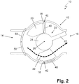
- Fig. 2 shows a further schematic representation of the Lucasausströmers 10 with a pivoted air guide element 20 and a closed air inlet opening 14. It should be noted that an air deflection at the in Fig. 2 shown position is not possible in principle, since the throttle valves 50 close the air inlet opening 14 and thus no air supply is possible.
- the representation of Fig. 2 however, is only schematic in nature, with two states shown simultaneously. For one thing shows Fig. 2 the design and function of the throttle 50, which can be moved toward each other together to close the air inlet opening 14. This is in Fig. 2 shown.
- Fig. 2 additionally shows a schematically indicated air passage through a lower partial air duct at a pivoted air guide 20.
- the upper fins 30 By pivoting the air guide 20, the upper fins 30 reach a rear area, so that the fins 30 are no longer in contact with the upper flap 40. As a result, no pressure is exerted on the flap 40, so that it is pressed via the spring device in the upper part of the air duct. The upper flap 40 therefore closes this partial air duct. Inflowing air would therefore not enter this partial air duct, but only flow out via the lower partial air duct.
- an air deflection is achieved, as indicated schematically by the arrow.
- the pivoting of the air guiding element 20 can take place via the operating element, not shown in the figures.
- the handle 22 can also be grasped and moved accordingly in order to pivot the air-conducting element 20.
- the air vent 10 allows for intuitive operation, with raising or pivoting of the air directing element 20 upwardly automatically causes air deflection upwards.
- the lamellae 30 of the group of fins are also moved by pivoting the air guide 20 in the direction of the air outlet opening 16, which are located in the partial air passage over which the air is discharged.
- FIGS. 1 and 2 show an embodiment, which includes both a throttle device with throttle valves 50 and the flaps 40.
- the throttle valves 50 are primarily used to control the amount of air supplied and not to close the partial air channels. This function is taken over the flaps 40.
- the flaps 40 may also be only partially pivoted, wherein the slats 30 are located by pivoting the air guide 20 in corresponding positions. The intermediate positions of the flaps 40 are not shown in the figures. However, it is obvious that this can be done by throttling an air flow over one of the partial air ducts. This results in different air deflections.
- a small distance between the roller-shaped portion 24 and the opposite edges of the flaps 40 can also exist in a closed state of a partial air channel, whereby disturbing noises (eg whistling) are prevented or minimized.
- disturbing noises eg whistling
- Low air currents have no influence on the air deflection and are therefore tolerable.
- the formation of the fins 30 is decisive for the degree to which the flaps 40 are pivoted in the respective positions. Therefore, the flaps 40 and the fins 30 are always tuned to the formation of the housing 12 and the air guide 20 so that in maximum deflection positions a closure of the corresponding partial air ducts is possible and intermediate positions of the flaps 40 can be achieved with appropriately pivoted air guide elements 20 to air deflection to reach up and down. In embodiments with rotated Heilausströmern 10 of course, the air deflection can also be done laterally over the air guide 20, the blades 30 then cause an air deflection up and down.
- the air vent 10 allows a significantly improved lateral air deflection over the fins 30, since they are mounted directly on the air guide 20.
- the air deflection is additionally controlled by a corresponding throttling of the air flows in the partial air ducts, the blades 30 automatically regulate how far the flaps 40, the partial air ducts block.
- a very simple trained Heilausströmer 10 is provided, which additionally requires only a small space.
Landscapes
- Engineering & Computer Science (AREA)
- Mechanical Engineering (AREA)
- Physics & Mathematics (AREA)
- Thermal Sciences (AREA)
- Chemical & Material Sciences (AREA)
- Combustion & Propulsion (AREA)
- General Engineering & Computer Science (AREA)
- Air-Flow Control Members (AREA)
Applications Claiming Priority (2)
| Application Number | Priority Date | Filing Date | Title |
|---|---|---|---|
| DE102018102759 | 2018-02-07 | ||
| DE102018110093.0A DE102018110093A1 (de) | 2018-02-07 | 2018-04-26 | Luftausströmer |
Publications (2)
| Publication Number | Publication Date |
|---|---|
| EP3530505A1 true EP3530505A1 (fr) | 2019-08-28 |
| EP3530505B1 EP3530505B1 (fr) | 2020-03-11 |
Family
ID=67308570
Family Applications (1)
| Application Number | Title | Priority Date | Filing Date |
|---|---|---|---|
| EP18212464.4A Active EP3530505B1 (fr) | 2018-02-07 | 2018-12-13 | Dispositif d'écoulement d'air |
Country Status (2)
| Country | Link |
|---|---|
| EP (1) | EP3530505B1 (fr) |
| DE (1) | DE102018110093A1 (fr) |
Cited By (2)
| Publication number | Priority date | Publication date | Assignee | Title |
|---|---|---|---|---|
| DE102019201902A1 (de) * | 2019-02-13 | 2020-08-13 | Faurecia Innenraum Systeme Gmbh | Luftausströmer mit einem aerodynamischen Element zum Regulieren eines Luftstroms |
| DE102020201478A1 (de) | 2020-02-06 | 2021-08-12 | Faurecia Innenraum Systeme Gmbh | Entlüftungsöffnung |
Families Citing this family (1)
| Publication number | Priority date | Publication date | Assignee | Title |
|---|---|---|---|---|
| DE102019209515A1 (de) | 2019-06-28 | 2020-12-31 | Faurecia Interieur Industrie | Lüftung |
Citations (5)
| Publication number | Priority date | Publication date | Assignee | Title |
|---|---|---|---|---|
| DE4136822A1 (de) * | 1991-11-08 | 1993-05-13 | Bayerische Motoren Werke Ag | Luftausstroemvorrichtung fuer den innenraum von kraftfahrzeugen |
| US20130029582A1 (en) * | 2011-07-27 | 2013-01-31 | Toyoda Gosei Co., Ltd. | Air conditioner register |
| DE102013210055B3 (de) | 2013-05-29 | 2014-09-11 | Faurecia Innenraum Systeme Gmbh | Luftausströmer |
| FR3043449A1 (fr) * | 2015-11-06 | 2017-05-12 | Reydel Automotive Bv | Dispositif d'aerateur pour vehicule automobile |
| DE102017111011A1 (de) * | 2017-05-19 | 2017-07-27 | Dr. Schneider Kunststoffwerke Gmbh | Luftausströmer |
Family Cites Families (2)
| Publication number | Priority date | Publication date | Assignee | Title |
|---|---|---|---|---|
| DE102015017009B4 (de) * | 2015-12-30 | 2018-04-26 | Faurecia Innenraum Systeme Gmbh | Auslassvorrichtung |
| DE102016116358A1 (de) * | 2016-09-01 | 2018-03-01 | Fischer Automotive Systems Gmbh & Co. Kg | Luftausströmer |
-
2018
- 2018-04-26 DE DE102018110093.0A patent/DE102018110093A1/de not_active Withdrawn
- 2018-12-13 EP EP18212464.4A patent/EP3530505B1/fr active Active
Patent Citations (5)
| Publication number | Priority date | Publication date | Assignee | Title |
|---|---|---|---|---|
| DE4136822A1 (de) * | 1991-11-08 | 1993-05-13 | Bayerische Motoren Werke Ag | Luftausstroemvorrichtung fuer den innenraum von kraftfahrzeugen |
| US20130029582A1 (en) * | 2011-07-27 | 2013-01-31 | Toyoda Gosei Co., Ltd. | Air conditioner register |
| DE102013210055B3 (de) | 2013-05-29 | 2014-09-11 | Faurecia Innenraum Systeme Gmbh | Luftausströmer |
| FR3043449A1 (fr) * | 2015-11-06 | 2017-05-12 | Reydel Automotive Bv | Dispositif d'aerateur pour vehicule automobile |
| DE102017111011A1 (de) * | 2017-05-19 | 2017-07-27 | Dr. Schneider Kunststoffwerke Gmbh | Luftausströmer |
Cited By (3)
| Publication number | Priority date | Publication date | Assignee | Title |
|---|---|---|---|---|
| DE102019201902A1 (de) * | 2019-02-13 | 2020-08-13 | Faurecia Innenraum Systeme Gmbh | Luftausströmer mit einem aerodynamischen Element zum Regulieren eines Luftstroms |
| US11214127B2 (en) | 2019-02-13 | 2022-01-04 | Faurecia Innenraum Systeme Gmbh | Air vent with an aerodynamic element for regulating airflow |
| DE102020201478A1 (de) | 2020-02-06 | 2021-08-12 | Faurecia Innenraum Systeme Gmbh | Entlüftungsöffnung |
Also Published As
| Publication number | Publication date |
|---|---|
| EP3530505B1 (fr) | 2020-03-11 |
| DE102018110093A1 (de) | 2019-08-08 |
Similar Documents
| Publication | Publication Date | Title |
|---|---|---|
| EP3403859B1 (fr) | Dispositif d'écoulement d'air | |
| DE102017113906B4 (de) | Luftausströmer | |
| EP3405357B1 (fr) | Aérateur d'air avec contrôle de direction du flux d'air | |
| EP3530506B1 (fr) | Dispositif d'écoulement d'air | |
| DE102008050180B4 (de) | Luftauslassdüse | |
| EP3321113B1 (fr) | Dispositif d'écoulement d'air | |
| EP3321114A1 (fr) | Dispositif d'écoulement d'air | |
| DE19549200A1 (de) | Windleitelement für ein Fahrzeugdach | |
| DE2153743B2 (de) | Luftdüse für eine Belüftungsanlage | |
| EP3530505A1 (fr) | Dispositif d'écoulement d'air | |
| EP3381725B1 (fr) | Aérateur | |
| EP1270286B1 (fr) | Dispositif pour diriger l'air, notamment pour un véhicule | |
| EP3870465B1 (fr) | Ensemble de paliers et diffuseur d'air comprenant un ensemble de paliers de ce type | |
| DE10127347A1 (de) | Vorrichtung zur Steuerung des Öffnungswinkels von Lüfterklappen einer Fahrzeugbelüftungs-/-klimaanlage | |
| DE102017003289A1 (de) | Belüftungsanordnung mit beweglicher Entfroster- und Innenraumbelüftungsdüse | |
| EP3560738A1 (fr) | Dispositif d'écoulement d'air | |
| DE202018104942U1 (de) | Luftausströmer | |
| EP3790749B1 (fr) | Diffuseur d'air pour un véhicule automobile | |
| DE102021111535A1 (de) | Luftausströmeranordnung | |
| DE102019100992B4 (de) | Luftablenkeinrichtung für einen Luftausströmer und Luftausströmer | |
| DE102016122138A1 (de) | Luftausströmer | |
| WO2019105706A1 (fr) | Diffuseur d'air | |
| DE102019132921B4 (de) | Luftausströmer mit Bedieneinrichtung | |
| DE102021125427A1 (de) | Luftausströmer für ein fahrzeug | |
| DE102019106963A1 (de) | Luftausströmer |
Legal Events
| Date | Code | Title | Description |
|---|---|---|---|
| PUAI | Public reference made under article 153(3) epc to a published international application that has entered the european phase |
Free format text: ORIGINAL CODE: 0009012 |
|
| STAA | Information on the status of an ep patent application or granted ep patent |
Free format text: STATUS: THE APPLICATION HAS BEEN PUBLISHED |
|
| AK | Designated contracting states |
Kind code of ref document: A1 Designated state(s): AL AT BE BG CH CY CZ DE DK EE ES FI FR GB GR HR HU IE IS IT LI LT LU LV MC MK MT NL NO PL PT RO RS SE SI SK SM TR |
|
| AX | Request for extension of the european patent |
Extension state: BA ME |
|
| STAA | Information on the status of an ep patent application or granted ep patent |
Free format text: STATUS: REQUEST FOR EXAMINATION WAS MADE |
|
| 17P | Request for examination filed |
Effective date: 20190910 |
|
| RBV | Designated contracting states (corrected) |
Designated state(s): AL AT BE BG CH CY CZ DE DK EE ES FI FR GB GR HR HU IE IS IT LI LT LU LV MC MK MT NL NO PL PT RO RS SE SI SK SM TR |
|
| GRAP | Despatch of communication of intention to grant a patent |
Free format text: ORIGINAL CODE: EPIDOSNIGR1 |
|
| STAA | Information on the status of an ep patent application or granted ep patent |
Free format text: STATUS: GRANT OF PATENT IS INTENDED |
|
| INTG | Intention to grant announced |
Effective date: 20191217 |
|
| GRAS | Grant fee paid |
Free format text: ORIGINAL CODE: EPIDOSNIGR3 |
|
| GRAA | (expected) grant |
Free format text: ORIGINAL CODE: 0009210 |
|
| STAA | Information on the status of an ep patent application or granted ep patent |
Free format text: STATUS: THE PATENT HAS BEEN GRANTED |
|
| AK | Designated contracting states |
Kind code of ref document: B1 Designated state(s): AL AT BE BG CH CY CZ DE DK EE ES FI FR GB GR HR HU IE IS IT LI LT LU LV MC MK MT NL NO PL PT RO RS SE SI SK SM TR |
|
| REG | Reference to a national code |
Ref country code: GB Ref legal event code: FG4D Free format text: NOT ENGLISH |
|
| REG | Reference to a national code |
Ref country code: CH Ref legal event code: EP |
|
| REG | Reference to a national code |
Ref country code: AT Ref legal event code: REF Ref document number: 1242709 Country of ref document: AT Kind code of ref document: T Effective date: 20200315 |
|
| REG | Reference to a national code |
Ref country code: IE Ref legal event code: FG4D Free format text: LANGUAGE OF EP DOCUMENT: GERMAN |
|
| REG | Reference to a national code |
Ref country code: DE Ref legal event code: R096 Ref document number: 502018000942 Country of ref document: DE |
|
| PG25 | Lapsed in a contracting state [announced via postgrant information from national office to epo] |
Ref country code: NO Free format text: LAPSE BECAUSE OF FAILURE TO SUBMIT A TRANSLATION OF THE DESCRIPTION OR TO PAY THE FEE WITHIN THE PRESCRIBED TIME-LIMIT Effective date: 20200611 Ref country code: RS Free format text: LAPSE BECAUSE OF FAILURE TO SUBMIT A TRANSLATION OF THE DESCRIPTION OR TO PAY THE FEE WITHIN THE PRESCRIBED TIME-LIMIT Effective date: 20200311 Ref country code: FI Free format text: LAPSE BECAUSE OF FAILURE TO SUBMIT A TRANSLATION OF THE DESCRIPTION OR TO PAY THE FEE WITHIN THE PRESCRIBED TIME-LIMIT Effective date: 20200311 |
|
| REG | Reference to a national code |
Ref country code: NL Ref legal event code: MP Effective date: 20200311 |
|
| PG25 | Lapsed in a contracting state [announced via postgrant information from national office to epo] |
Ref country code: BG Free format text: LAPSE BECAUSE OF FAILURE TO SUBMIT A TRANSLATION OF THE DESCRIPTION OR TO PAY THE FEE WITHIN THE PRESCRIBED TIME-LIMIT Effective date: 20200611 Ref country code: LV Free format text: LAPSE BECAUSE OF FAILURE TO SUBMIT A TRANSLATION OF THE DESCRIPTION OR TO PAY THE FEE WITHIN THE PRESCRIBED TIME-LIMIT Effective date: 20200311 Ref country code: SE Free format text: LAPSE BECAUSE OF FAILURE TO SUBMIT A TRANSLATION OF THE DESCRIPTION OR TO PAY THE FEE WITHIN THE PRESCRIBED TIME-LIMIT Effective date: 20200311 Ref country code: HR Free format text: LAPSE BECAUSE OF FAILURE TO SUBMIT A TRANSLATION OF THE DESCRIPTION OR TO PAY THE FEE WITHIN THE PRESCRIBED TIME-LIMIT Effective date: 20200311 Ref country code: GR Free format text: LAPSE BECAUSE OF FAILURE TO SUBMIT A TRANSLATION OF THE DESCRIPTION OR TO PAY THE FEE WITHIN THE PRESCRIBED TIME-LIMIT Effective date: 20200612 |
|
| REG | Reference to a national code |
Ref country code: LT Ref legal event code: MG4D |
|
| PG25 | Lapsed in a contracting state [announced via postgrant information from national office to epo] |
Ref country code: NL Free format text: LAPSE BECAUSE OF FAILURE TO SUBMIT A TRANSLATION OF THE DESCRIPTION OR TO PAY THE FEE WITHIN THE PRESCRIBED TIME-LIMIT Effective date: 20200311 |
|
| PG25 | Lapsed in a contracting state [announced via postgrant information from national office to epo] |
Ref country code: SM Free format text: LAPSE BECAUSE OF FAILURE TO SUBMIT A TRANSLATION OF THE DESCRIPTION OR TO PAY THE FEE WITHIN THE PRESCRIBED TIME-LIMIT Effective date: 20200311 Ref country code: EE Free format text: LAPSE BECAUSE OF FAILURE TO SUBMIT A TRANSLATION OF THE DESCRIPTION OR TO PAY THE FEE WITHIN THE PRESCRIBED TIME-LIMIT Effective date: 20200311 Ref country code: PT Free format text: LAPSE BECAUSE OF FAILURE TO SUBMIT A TRANSLATION OF THE DESCRIPTION OR TO PAY THE FEE WITHIN THE PRESCRIBED TIME-LIMIT Effective date: 20200805 Ref country code: LT Free format text: LAPSE BECAUSE OF FAILURE TO SUBMIT A TRANSLATION OF THE DESCRIPTION OR TO PAY THE FEE WITHIN THE PRESCRIBED TIME-LIMIT Effective date: 20200311 Ref country code: CZ Free format text: LAPSE BECAUSE OF FAILURE TO SUBMIT A TRANSLATION OF THE DESCRIPTION OR TO PAY THE FEE WITHIN THE PRESCRIBED TIME-LIMIT Effective date: 20200311 Ref country code: IS Free format text: LAPSE BECAUSE OF FAILURE TO SUBMIT A TRANSLATION OF THE DESCRIPTION OR TO PAY THE FEE WITHIN THE PRESCRIBED TIME-LIMIT Effective date: 20200711 Ref country code: SK Free format text: LAPSE BECAUSE OF FAILURE TO SUBMIT A TRANSLATION OF THE DESCRIPTION OR TO PAY THE FEE WITHIN THE PRESCRIBED TIME-LIMIT Effective date: 20200311 Ref country code: RO Free format text: LAPSE BECAUSE OF FAILURE TO SUBMIT A TRANSLATION OF THE DESCRIPTION OR TO PAY THE FEE WITHIN THE PRESCRIBED TIME-LIMIT Effective date: 20200311 |
|
| REG | Reference to a national code |
Ref country code: DE Ref legal event code: R097 Ref document number: 502018000942 Country of ref document: DE |
|
| PLBE | No opposition filed within time limit |
Free format text: ORIGINAL CODE: 0009261 |
|
| STAA | Information on the status of an ep patent application or granted ep patent |
Free format text: STATUS: NO OPPOSITION FILED WITHIN TIME LIMIT |
|
| PG25 | Lapsed in a contracting state [announced via postgrant information from national office to epo] |
Ref country code: IT Free format text: LAPSE BECAUSE OF FAILURE TO SUBMIT A TRANSLATION OF THE DESCRIPTION OR TO PAY THE FEE WITHIN THE PRESCRIBED TIME-LIMIT Effective date: 20200311 Ref country code: DK Free format text: LAPSE BECAUSE OF FAILURE TO SUBMIT A TRANSLATION OF THE DESCRIPTION OR TO PAY THE FEE WITHIN THE PRESCRIBED TIME-LIMIT Effective date: 20200311 Ref country code: ES Free format text: LAPSE BECAUSE OF FAILURE TO SUBMIT A TRANSLATION OF THE DESCRIPTION OR TO PAY THE FEE WITHIN THE PRESCRIBED TIME-LIMIT Effective date: 20200311 |
|
| 26N | No opposition filed |
Effective date: 20201214 |
|
| PG25 | Lapsed in a contracting state [announced via postgrant information from national office to epo] |
Ref country code: PL Free format text: LAPSE BECAUSE OF FAILURE TO SUBMIT A TRANSLATION OF THE DESCRIPTION OR TO PAY THE FEE WITHIN THE PRESCRIBED TIME-LIMIT Effective date: 20200311 |
|
| PG25 | Lapsed in a contracting state [announced via postgrant information from national office to epo] |
Ref country code: MC Free format text: LAPSE BECAUSE OF FAILURE TO SUBMIT A TRANSLATION OF THE DESCRIPTION OR TO PAY THE FEE WITHIN THE PRESCRIBED TIME-LIMIT Effective date: 20200311 |
|
| REG | Reference to a national code |
Ref country code: BE Ref legal event code: MM Effective date: 20201231 |
|
| PG25 | Lapsed in a contracting state [announced via postgrant information from national office to epo] |
Ref country code: LU Free format text: LAPSE BECAUSE OF NON-PAYMENT OF DUE FEES Effective date: 20201213 Ref country code: IE Free format text: LAPSE BECAUSE OF NON-PAYMENT OF DUE FEES Effective date: 20201213 |
|
| PG25 | Lapsed in a contracting state [announced via postgrant information from national office to epo] |
Ref country code: TR Free format text: LAPSE BECAUSE OF FAILURE TO SUBMIT A TRANSLATION OF THE DESCRIPTION OR TO PAY THE FEE WITHIN THE PRESCRIBED TIME-LIMIT Effective date: 20200311 Ref country code: MT Free format text: LAPSE BECAUSE OF FAILURE TO SUBMIT A TRANSLATION OF THE DESCRIPTION OR TO PAY THE FEE WITHIN THE PRESCRIBED TIME-LIMIT Effective date: 20200311 Ref country code: CY Free format text: LAPSE BECAUSE OF FAILURE TO SUBMIT A TRANSLATION OF THE DESCRIPTION OR TO PAY THE FEE WITHIN THE PRESCRIBED TIME-LIMIT Effective date: 20200311 |
|
| PG25 | Lapsed in a contracting state [announced via postgrant information from national office to epo] |
Ref country code: MK Free format text: LAPSE BECAUSE OF FAILURE TO SUBMIT A TRANSLATION OF THE DESCRIPTION OR TO PAY THE FEE WITHIN THE PRESCRIBED TIME-LIMIT Effective date: 20200311 Ref country code: AL Free format text: LAPSE BECAUSE OF FAILURE TO SUBMIT A TRANSLATION OF THE DESCRIPTION OR TO PAY THE FEE WITHIN THE PRESCRIBED TIME-LIMIT Effective date: 20200311 |
|
| PG25 | Lapsed in a contracting state [announced via postgrant information from national office to epo] |
Ref country code: BE Free format text: LAPSE BECAUSE OF NON-PAYMENT OF DUE FEES Effective date: 20201231 |
|
| REG | Reference to a national code |
Ref country code: CH Ref legal event code: PL |
|
| PG25 | Lapsed in a contracting state [announced via postgrant information from national office to epo] |
Ref country code: LI Free format text: LAPSE BECAUSE OF NON-PAYMENT OF DUE FEES Effective date: 20211231 Ref country code: CH Free format text: LAPSE BECAUSE OF NON-PAYMENT OF DUE FEES Effective date: 20211231 |
|
| P01 | Opt-out of the competence of the unified patent court (upc) registered |
Effective date: 20230525 |
|
| PG25 | Lapsed in a contracting state [announced via postgrant information from national office to epo] |
Ref country code: SI Free format text: LAPSE BECAUSE OF FAILURE TO SUBMIT A TRANSLATION OF THE DESCRIPTION OR TO PAY THE FEE WITHIN THE PRESCRIBED TIME-LIMIT Effective date: 20200311 |
|
| PGFP | Annual fee paid to national office [announced via postgrant information from national office to epo] |
Ref country code: GB Payment date: 20231218 Year of fee payment: 6 |
|
| PGFP | Annual fee paid to national office [announced via postgrant information from national office to epo] |
Ref country code: FR Payment date: 20231220 Year of fee payment: 6 Ref country code: DE Payment date: 20231129 Year of fee payment: 6 |