EP3530496B1 - Aufweitvorrichtung von platten - Google Patents
Aufweitvorrichtung von platten Download PDFInfo
- Publication number
- EP3530496B1 EP3530496B1 EP18159993.7A EP18159993A EP3530496B1 EP 3530496 B1 EP3530496 B1 EP 3530496B1 EP 18159993 A EP18159993 A EP 18159993A EP 3530496 B1 EP3530496 B1 EP 3530496B1
- Authority
- EP
- European Patent Office
- Prior art keywords
- panels
- constituent
- constituent member
- arm member
- panel
- Prior art date
- Legal status (The legal status is an assumption and is not a legal conclusion. Google has not performed a legal analysis and makes no representation as to the accuracy of the status listed.)
- Active
Links
Images


Classifications
-
- E—FIXED CONSTRUCTIONS
- E04—BUILDING
- E04B—GENERAL BUILDING CONSTRUCTIONS; WALLS, e.g. PARTITIONS; ROOFS; FLOORS; CEILINGS; INSULATION OR OTHER PROTECTION OF BUILDINGS
- E04B2/00—Walls, e.g. partitions, for buildings; Wall construction with regard to insulation; Connections specially adapted to walls
- E04B2/74—Removable non-load-bearing partitions; Partitions with a free upper edge
- E04B2/7407—Removable non-load-bearing partitions; Partitions with a free upper edge assembled using frames with infill panels or coverings only; made-up of panels and a support structure incorporating posts
- E04B2/7416—Removable non-load-bearing partitions; Partitions with a free upper edge assembled using frames with infill panels or coverings only; made-up of panels and a support structure incorporating posts with free upper edge, e.g. for use as office space dividers
- E04B2/7433—Removable non-load-bearing partitions; Partitions with a free upper edge assembled using frames with infill panels or coverings only; made-up of panels and a support structure incorporating posts with free upper edge, e.g. for use as office space dividers with panels and support posts
- E04B2/7438—Removable non-load-bearing partitions; Partitions with a free upper edge assembled using frames with infill panels or coverings only; made-up of panels and a support structure incorporating posts with free upper edge, e.g. for use as office space dividers with panels and support posts with adjustable angular connection of panels to posts
- E04B2/7442—Removable non-load-bearing partitions; Partitions with a free upper edge assembled using frames with infill panels or coverings only; made-up of panels and a support structure incorporating posts with free upper edge, e.g. for use as office space dividers with panels and support posts with adjustable angular connection of panels to posts hinged connections
-
- B—PERFORMING OPERATIONS; TRANSPORTING
- B60—VEHICLES IN GENERAL
- B60D—VEHICLE CONNECTIONS
- B60D5/00—Gangways for coupled vehicles, e.g. of concertina type
-
- B—PERFORMING OPERATIONS; TRANSPORTING
- B61—RAILWAYS
- B61D—BODY DETAILS OR KINDS OF RAILWAY VEHICLES
- B61D17/00—Construction details of vehicle bodies
- B61D17/04—Construction details of vehicle bodies with bodies of metal; with composite, e.g. metal and wood body structures
- B61D17/20—Communication passages between coaches; Adaptation of coach ends therefor
-
- B—PERFORMING OPERATIONS; TRANSPORTING
- B60—VEHICLES IN GENERAL
- B60D—VEHICLE CONNECTIONS
- B60D5/00—Gangways for coupled vehicles, e.g. of concertina type
- B60D5/006—Passages between articulated vehicles, e.g. bridges or rotating plates
-
- B—PERFORMING OPERATIONS; TRANSPORTING
- B61—RAILWAYS
- B61D—BODY DETAILS OR KINDS OF RAILWAY VEHICLES
- B61D17/00—Construction details of vehicle bodies
- B61D17/04—Construction details of vehicle bodies with bodies of metal; with composite, e.g. metal and wood body structures
- B61D17/20—Communication passages between coaches; Adaptation of coach ends therefor
- B61D17/22—Communication passages between coaches; Adaptation of coach ends therefor flexible, e.g. bellows
-
- E—FIXED CONSTRUCTIONS
- E04—BUILDING
- E04B—GENERAL BUILDING CONSTRUCTIONS; WALLS, e.g. PARTITIONS; ROOFS; FLOORS; CEILINGS; INSULATION OR OTHER PROTECTION OF BUILDINGS
- E04B1/00—Constructions in general; Structures which are not restricted either to walls, e.g. partitions, or floors or ceilings or roofs
- E04B1/38—Connections for building structures in general
- E04B1/388—Separate connecting elements
-
- E—FIXED CONSTRUCTIONS
- E04—BUILDING
- E04B—GENERAL BUILDING CONSTRUCTIONS; WALLS, e.g. PARTITIONS; ROOFS; FLOORS; CEILINGS; INSULATION OR OTHER PROTECTION OF BUILDINGS
- E04B1/00—Constructions in general; Structures which are not restricted either to walls, e.g. partitions, or floors or ceilings or roofs
- E04B1/38—Connections for building structures in general
- E04B1/61—Connections for building structures in general of slab-shaped building elements with each other
- E04B1/6104—Connections for building structures in general of slab-shaped building elements with each other the overlapping ends of the slabs connected together
-
- E—FIXED CONSTRUCTIONS
- E04—BUILDING
- E04B—GENERAL BUILDING CONSTRUCTIONS; WALLS, e.g. PARTITIONS; ROOFS; FLOORS; CEILINGS; INSULATION OR OTHER PROTECTION OF BUILDINGS
- E04B1/00—Constructions in general; Structures which are not restricted either to walls, e.g. partitions, or floors or ceilings or roofs
- E04B1/343—Structures characterised by movable, separable, or collapsible parts, e.g. for transport
- E04B1/344—Structures characterised by movable, separable, or collapsible parts, e.g. for transport with hinged parts
- E04B1/3448—Structures characterised by movable, separable, or collapsible parts, e.g. for transport with hinged parts with rotating shell-forming segments
-
- E—FIXED CONSTRUCTIONS
- E04—BUILDING
- E04B—GENERAL BUILDING CONSTRUCTIONS; WALLS, e.g. PARTITIONS; ROOFS; FLOORS; CEILINGS; INSULATION OR OTHER PROTECTION OF BUILDINGS
- E04B1/00—Constructions in general; Structures which are not restricted either to walls, e.g. partitions, or floors or ceilings or roofs
- E04B1/38—Connections for building structures in general
- E04B1/61—Connections for building structures in general of slab-shaped building elements with each other
- E04B1/6108—Connections for building structures in general of slab-shaped building elements with each other the frontal surfaces of the slabs connected together
- E04B1/612—Connections for building structures in general of slab-shaped building elements with each other the frontal surfaces of the slabs connected together by means between frontal surfaces
- E04B1/6125—Connections for building structures in general of slab-shaped building elements with each other the frontal surfaces of the slabs connected together by means between frontal surfaces with protrusions on the one frontal surface co-operating with recesses in the other frontal surface
- E04B1/6129—Connections for building structures in general of slab-shaped building elements with each other the frontal surfaces of the slabs connected together by means between frontal surfaces with protrusions on the one frontal surface co-operating with recesses in the other frontal surface the connection made by expansion
Definitions
- the present invention relates to an expansion device of panels.
- An expansion device 101 of panels shown in FIGS. 12 and 13 has been known as a device constituting an inner wall such as a sidewall, an upper wall, or a lower wall of a connecting passage formed inside a hood provided between bodies of rolling stock.
- EP 0 722 873 A1 discloses such an expansion device.
- the expansion device 101 of panels includes side panels 102, 103 coupled to end surfaces 110a, 111a of bodies 110, 111 that are coupled to each other rotatably around axes 102a, 103a in an up and down direction respectively and a central panel 104 provided on an outer side of the side panels 102, 103 is arranged so as to be positioned in a substantially central portion between the end surfaces 110a, 111a and movable in a direction between the end surfaces 110a, 111a due to a link member 105.
- link member 105 is connected to the outer side of the central panel 104 and also both sides thereof are rotatably connected to axes 1 10b, 111b in the up and down direction provided on the end surfaces 1 10a, 111a of the bodies 110, 111.
- the expansion device 101 of panels constitutes inner walls 114 such as a sidewall, an upper wall, and a lower wall of a connecting passage 113 provided in the bodies 110, 111.
- the length in the direction between the end surfaces 1 10a, 111a of the bodies 110, 111 cannot be made shorter than the length in a state in which inner-side tips of the side panels 102, 103 abut on each other and it is necessary to increase the number of panels to make the length shorter.
- the side panels 102, 103 are rotatably connected to the end surfaces 110a, 111a
- the central panel 104 is connected to the link member 105
- the side panels 102, 103 and the central panel 104 are controlled by different mechanisms and so a problem that it is difficult to increase the number of panels with ease is posed.
- An object of the present invention is to propose an expansion device of panels capable of making shorter the length in a direction of both ends thereof when the length is made the shortest by, compared with an expansion device of panels of the conventional technology, increasing the number of panels.
- the present invention includes a first constituent member constructed such that at least portions of a plurality of panels overlap and a second constituent member constructed such that at least portions of a plurality of panels overlap,
- the link member may include a first main arm member and a second main arm member arranged mutually in an X shape,
- the first constituent member and the second constituent member may be connected such that each can be parallel to or in an inclined positional relation to a direction of movement of members constituting the link member.
- the expansion device of panels may be provided between bodies of rolling stock.
- the present invention includes a first constituent member constructed such that at least portions of a plurality of panels overlap and a second constituent member constructed such that at least portions of a plurality of panels overlap, in which the first constituent member and the second constituent member are connected to a link member that can be expanded and contracted, the first constituent member and the second constituent member are expanded and contracted by expansion and contraction of the link member, and the first constituent member and the second constituent member can relatively be rotated around rotation axes so that the number of constituent panels can be made larger than that of the conventional technology and also the maximum length between both ends thereof can be made longer and the minimum length can be made shorter.
- the expansion device of panels according to the present invention can suitably be used as constituting at least one of a sidewall, an upper wall, and a lower wall as inner walls of a connecting passage provided between bodies of a vehicle including a plurality of bodies such as rolling stock and a connected bus and in the following embodiments, the description is based on embodiments applied to the sidewall of a connecting passage of rolling stock.
- profile lines are omitted to avoid complication of diagrams.
- FIG. 1 is a top view when an expansion device 1 of panels according to a first embodiment of the present invention is applied as a sidewall 9D of a connecting passage 9C by providing the expansion device 1 between bodies 9A, 9B of rolling stock.
- an A-A direction in FIG. 2 is assumed to be an up and down direction
- a B-B direction to be a direction between end surfaces (horizontal direction) of bodies
- an upper side of FIG. 1 to be an inner side C
- a lower side to be an outer side D.
- the expansion device 1 of panels includes, as shown in FIGS. 1 and 2 , a first constituent member 2 and a second constituent member 3.
- the first constituent member 2 includes, as shown in FIGS. 1 and 2 , three panels of a first panel 4, a second panel 5, and a third panel 6 and these panels are disposed such that at least portions of neighboring panels overlap with each other in the B-B direction (horizontal direction) between end surfaces 9a, 9c of the bodies 9A, 9B.
- the second constituent member 3 includes, as shown in FIGS. 1 and 2 , three panels of a fourth panel 7, a fifth panel 8, and a sixth panel 9 and these panels are disposed such that at least portions of neighboring panels overlap with each other in the B-B direction (horizontal direction) between end surfaces 9a, 9c of the bodies 9A, 9B.
- the first panel 4 is formed such that, as shown in FIGS. 1 to 3 , an inner-side piece 4a and an outer-side piece 4b are formed substantially in parallel by a plate member being bent and also ends on the opposite side of the second panel 5 in the horizontal direction of the inner-side piece 4a and the outer-side piece 4b are connected by a connecting portion 4c so that the cross section thereof is formed in a U-shape and also the second panel 5 side in the horizontal B-B direction and the vertical A-A direction are open. Accordingly, a housing space 4d open on the second panel 5 side and in the vertical A-A direction is formed in the first panel 4. Also, as shown in FIGS. 1 to 3 , a notch 4e that is open only in a front and rear direction and on the second panel 5 side is formed in a vertical portion of the outer-side piece 4b of the first panel 4.
- the second panel 5 is formed such that an inner-side piece 5a and an outer-side piece 5b are formed substantially in parallel by a plate member being bent and also ends on the opposite side of the third panel 6 in the horizontal direction of the inner-side piece 5a and the outer-side piece 5b are connected by a connecting portion 5c so that the cross section thereof is formed in a U- shape and also the third panel 6 side in the horizontal B-B direction and the vertical A-A direction are open. Accordingly, a housing space 5d open on the third panel 6 side and in the vertical A-A direction is formed in the second panel 5. Also, as shown in FIGS. 1 to 3 , a notch 5e that is open only in the front and rear direction and on the third panel 6 side is formed in a vertical portion of the outer-side piece 5b of the second panel 5.
- the second panel 5 is housed, as shown in FIG. 1 , inside the housing space 4d of the first panel 4 in such a way that the third panel 6 side protrudes and also disposed slidably with respect to the first panel 4 in an overlapping direction of panels such as the horizontal B-B direction or the vertical A-A direction.
- the third panel 6 is formed from a plate member, one end thereof in the horizontal B-B direction is connected to the end surface 9a of one body 9A rotatably around a rotation axis 9b in the up and down direction, the other end in the horizontal B-B direction of the third panel 6 is housed inside the housing space 5d of the second panel 5 such that the end surface 9a side protrudes. Also, the third panel 6 is relatively slidably with respect to the second panel 5 in the horizontal B-B direction and the vertical A-A direction.
- the fourth panel 7 is formed, as shown in FIG. 1 , in a structure obtained by horizontally inverting the first panel 4 in the horizontal B-B direction
- the fifth panel 8 is formed in a structure obtained by horizontally inverting the second panel 5 in the horizontal B-B direction
- the sixth panel 9 is formed in a structure obtained by horizontally inverting the third panel 6 in the horizontal B-B direction.
- the fifth panel 8 is housed, as shown in FIG. 1 , inside a housing space 7d of the fourth panel 7 in such a way that the sixth panel 9 side protrudes and also disposed slidably with respect to the fourth panel 7 in the horizontal B-B direction and the vertical A-A direction.
- the other end of the sixth panel 9 is connected to the end surface 9c of the other body 9B rotatably around a rotation axis 9d in the up and down direction and one end in the horizontal B-B direction of the sixth panel 9 is housed inside a housing space 8d of the fifth panel 8 such that the end surface 9c side protrudes.
- the sixth panel 9 is relatively slidably with respect to the fifth panel 8 in an overlapping direction of panels such as the horizontal B-B direction or the vertical A-A direction.
- a columnar member 10 formed like a rectangular column is provided upright, as shown in FIGS. 1 to 3 , between the first constituent member 2 and the second constituent member 3 substantially entirely in the vertical A-A direction.
- the first panel 4 of the first constituent member 2 is perpendicular to the upright direction of the columnar member 10 and also connected rotatably around a rotation axis 11 provided in the horizontal B-B direction.
- the fourth panel 7 of the second constituent member 3 is perpendicular to the upright direction of the columnar member 10 and also connected rotatably around a rotation axis 12 provided in the horizontal B-B direction.
- first constituent member 2 and the second constituent member 3 are perpendicular to the upright direction of the columnar member 10 and also can relatively rotate around the rotation axes 11, 12 provided in the horizontal B-B direction.
- link members 15, 15 that can be expanded and contracted are connected to the first constituent member 2 and the second constituent member 3 in upper and lower portions thereof.
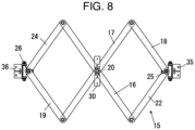
- the link member 15 includes, as shown in FIG. 4 , a first main arm member 16 and a second main arm member 17 formed like a long flat plate and the first main arm member 16 and the second main arm member 17 are connected in respective central portions in the axial direction in an X shape rotatably around a rotation axis 20 in the front and rear direction of the main arm members 16, 17.
- first parallel arm member 18 formed like a long flat plate is rotatably connected to one end 17a of the second main arm member 17. Further, the first parallel arm member 18 is disposed so as to be parallel to the first main arm member 16.
- One end 19a of a second parallel arm member 19 formed like a long flat plate is rotatably connected to the other end 17b of the second main arm member 17. Further, the second parallel arm member 19 is disposed so as to be parallel to the first main arm member 16 and the first parallel arm member 18.
- first connecting arm member 21 formed like a long flat plate is rotatably connected to the central portion in the axial direction of the first parallel arm member 18 and the other end 21b thereof is rotatably connected to the central portion between the rotation axis 20 and one end 16a of the first main arm member 16. Further, the first connecting arm member 21 is disposed so as to be parallel to the second main arm member 17.
- One end 22a of a second connecting arm member 22 formed like a long flat plate is connected to one end 18a of the first parallel arm member 18 rotatably around a rotation axis 25 and the other end 22b thereof is rotatably connected to the one end 16a of the first main arm member 16. Further, the second connecting arm member 22 is disposed so as to be parallel to the second main arm member 17 and the first connecting arm member 21. Incidentally, the second connecting arm member 22 may not be provided.
- One end 23a of a third connecting arm member 23 formed like a long flat plate is rotatably connected to the central portion between the rotation axis 20 and the other end 16b of the first main arm member 16 and the other end 23b thereof is rotatably connected to the central portion in the axial direction of the second parallel arm member 19. Further, the third connecting arm member 23 is disposed so as to be parallel to the second main arm member 17.
- One end 24a of a fourth connecting arm member 24 formed like a long flat plate is connected to the other end 16b of the first main arm member 16 and the other end 24b thereof is connected to the other end 19b of the second parallel arm member 19 rotatably around a rotation axis 26. Further, the fourth connecting arm member 24 is disposed so as to be parallel to the second main arm member 17 and the third connecting arm member 23. Incidentally, the fourth connecting arm member 24 may not be provided.
- connecting arm members 21, 22, 23, 24 are provided in parallel between the first main arm member 16 and the parallel arm members 18, 19.
- the link members 15 constitute a parallel link and can expand a distance L1 between the rotation axis 25 provided in the first parallel arm member 18 and the rotation axis 26 provided in the second parallel arm member 19, as shown in FIG. 5 , from the state shown in FIG. 4 or contract the distance L1, as shown in FIG. 6 .
- the rotation axis 20 of the link member 15 is disposed so as to be perpendicular to the upright direction (A-A direction) of the columnar member 10 with respect to the columnar member 10 and also connected via a connecting member 30 including a rotation axis 30a provided in the upright direction (A-A direction) of the columnar member 10.
- the link member 15 can rotate clockwise and counterclockwise in FIG. 2 around the rotation axis 20 perpendicular to the upright direction (A-A direction) of the columnar member 10 with respect to the columnar member 10 and also rotate in the up and down direction of FIG. 1 (the front and rear direction of FIG. 2 ) around a rotation axis 30b provided in the upright direction thereof so that the direction of movement of the members 16, 17, 18, 19, 21, 22, 23, 24 constituting the link member 15 can be made to be parallel to an outer side surface of the columnar member 10 or in an inclined positional relation thereto.
- the rotation axis 20 of at least one link member 15 of the two link members 15, 15 can move in the upright direction (A-A direction) of the columnar member 10 with respect to the columnar member 10.
- a rotation axis 32 projected so as to be perpendicular, as shown in FIG. 3 , to the outer-side piece 5b is disposed in the second panel 5 of the first constituent member 2 so as to be positioned in the notch 4e of the first panel 4 so that, when the first panel 4 slides relative to the second panel 5 in an overlapping direction of panels such as the horizontal B-B direction or the vertical A-A direction, the rotation axis 32 and the first panel 4 will not interfere with each other.
- a connecting hole 21c provided in the central portion in the axial direction of the first connecting arm member 21 is loosely fitted and rotatably connected to the rotation axis 32.
- the rotation axis 32 may be provided on the first connecting arm member 21 side by forming the connecting hole 21c on the outer-side piece 5b side of the second panel 5.
- a rotation axis 33 projected so as to be perpendicular to an outer-side piece 8b is disposed in the fifth panel 8 of the second constituent member 3 so as to be positioned, as shown in FIG. 2 , in a notch 7e of the fourth panel 7 so that, when the fourth panel 7 slides relative to the fifth panel 8 in an overlapping direction of panels such as the horizontal B-B direction or the vertical A-A direction, the rotation axis 33 and the fourth panel 7 will not interfere with each other.
- a connecting hole 23c provided in the central portion in the axial direction of the third connecting arm member 23 is loosely fitted and rotatably connected to the rotation axis 33.
- the rotation axis 33 may be provided on the third connecting arm member 23 side by forming the connecting hole 23c on the outer-side piece 8b side of the fifth panel 8.
- connecting arm members 21, 23 With connecting holes 21a, 23a of the connecting arm members 21, 23 loosely fitted to the rotation axes 32, 33, when the link member 15 rotates around a rotation axis 30b provided in the upright direction with respect to the columnar member 10 to be in a mutually inclined relation, the connecting arm members 21, 23 can move in an inward and outward direction of the bodies 9A, 9B and be in an inclined relation with respect to the rotation axes 32, 33.
- a connecting arm member 35 is connected to the rotation axis 25 provided in the first parallel arm member 18 rotatably around a rotation axis 35a perpendicular to the rotation axis 25. Also, the connecting arm member 35 can rotate around a rotation axis 35b perpendicular to the rotation axis 35a. Further, the connecting arm member 35 is securely installed on the outer side of an outer-side piece 6b of the third panel 6 in the first constituent member 2. That is, the connecting arm member 35 includes a free joint capable of rotating in any direction and a rotation axis 25 portion provided in the first parallel arm member 18 is connected to the outer side of the third panel 6 via the free joint.
- the connecting arm member 35 is provided so as to be positioned in the notch 5e of the second panel 5 and, when the third panel 6 slides relative to the second panel 5 in an overlapping direction of panels such as the horizontal B-B direction or the vertical A-A direction, the connecting arm member 35 and the second panel 5 will not interfere with each other.
- a connecting arm member 36 is connected to the rotation axis 26 provided in the second parallel arm member 19 rotatably around a rotation axis 36a perpendicular to the rotation axis 26. Also, the connecting arm member 36 can rotate around a rotation axis 36b perpendicular to the rotation axis 36a. Further, the connecting arm member 36 is securely installed on the outer side of an outer-side piece 9b of the sixth panel 9 in the second constituent member 3. That is, the connecting arm member 36 includes a free joint capable of rotating in any direction and a rotation axis 26 portion provided in the second parallel arm member 19 is connected to the outer side of the sixth panel 9 via the free joint.
- the connecting arm member 36 is provided, as shown in FIG. 2 , so as to be positioned in the notch 8e of the fifth panel 8 and, when the sixth panel 9 slides relative to the fifth panel 8 in an overlapping direction of panels such as the horizontal B-B direction or the vertical A-A direction, the connecting arm member 36 and the fifth panel 8 will not interfere with each other.
- the panels 4, 5, 6 constituting the first constituent member 2 and the panels 7, 8, 9 constituting the second constituent member 3 each slide in an overlapping direction of panels (any direction on the paper of FIG. 2 ) such as the horizontal B-B direction or the vertical A-A direction accompanying expansion and contraction of the link member 15 and rotation around the rotation axis 20 of the link member 15 so that the first constituent member 2 and the second constituent member 3 can expand and contract in any direction of overlapping directions of panels.
- the direction of movement of the members 16, 17, 18, 19, 21, 22, 23, 24 constituting the link member 15 can be made parallel to or in an inclined positional relation with respect to the first constituent member 2 or the second constituent member 3. That is, the first constituent member 2 and the second constituent member 3 mutually rotate around the rotation axes 11, 12 and even if, for example, a state in which the constituent members 2, 3 and the link member 15 are parallel as shown in FIG.
- the link member 15 can rotate with respect to the first constituent member 2 and the second constituent member 3 around the rotation axes 35b, 36b of the connecting arm members 35, 36 and the rotation axis 30b of the connecting member 30 and in that state, the panels 4 to 9 constituting the first constituent member 2 and the second constituent member 3 can satisfactorily be moved by expanding or contracting.
- the expansion device 1 of panels can respond by the link member 15 being expanded or contracted in the horizontal B-B direction to allow the first constituent member 2 and the second constituent member 3 to expand or contract in the horizontal B-B direction.
- the expansion device 1 of panels can respond by the link member being rotated around the rotation axis 20 to allow panels constituting the first constituent member 2 and the second constituent member 3 to be mutually displaced in the vertical A-A direction.
- the expansion device 1 of panels can respond by only the link member 15 provided in the upper portion or the lower portion being contracted to allow only the upper portion or the lower portion of the first constituent member 2 and the second constituent member 3 to contract in the horizontal B-B direction.
- the expansion device 1 of panels can respond by, for example, the first constituent member 2 and the second constituent member 3 being mutually rotated around the rotation axes 11, 12 and also the link member 15 being inclined toward the first constituent member 2 and the second constituent member 3.
- the expansion device 1 of panels using six panels 4 to 9, compared with the conventional technology in which three panels 102, 103, 104 are used, the maximum length of the distance between the bodies 9A, 9B can be made longer and the minimum length thereof can be made shorter.
- the first constituent member 2 and the second constituent member 3 are each constituted using three panels, but the number of constituent panels can be set to any number if the number of panels constituting the first constituent member 2 and that constituting the second constituent member 3 are the same and the number of constituent panels is equal to 2 or greater.
- each constituent member can be constituted using two panels by using the first main arm member 16, the second main arm member 17, the first parallel arm member 18, the second parallel arm member 19, the second connecting arm member 22, and the fourth connecting arm member 24 and also the first panel 4, the third panel 6, the fourth pane 7, and the sixth panel 9.
- the first constituent member 2 and that constituting the second constituent member 3 can each be constituted using four panels by increasing the number of connecting arm members provided in parallel with the second main arm member 17 between the first main arm member 16 and the first parallel arm member 18 by one for each of the first constituent member 2 side and the second constituent member 3 side, connecting arm members 50, 51, and connecting panels 52, 53 having a structure similar to that of the second panel 5 and the fifth panel 8 in the first embodiment to the connecting arm members 50, 51 that have been added.
- the other structure is the same as that of the first embodiment and the description thereof is omitted.
- the columnar member 10 is provided between the first constituent member 2 and the second constituent member 3, but without providing the columnar member 10, the first constituent member 2 and the second constituent member 3 may be mutually rotatably connected by a rotation axis similar to the rotation axes 11, 12 in the central portion in the up and down direction.
- the other structure is the same as that of the first and second embodiments and the description thereof is omitted.
Landscapes
- Engineering & Computer Science (AREA)
- Mechanical Engineering (AREA)
- Architecture (AREA)
- Wood Science & Technology (AREA)
- Life Sciences & Earth Sciences (AREA)
- Civil Engineering (AREA)
- Structural Engineering (AREA)
- Physics & Mathematics (AREA)
- Electromagnetism (AREA)
- Tents Or Canopies (AREA)
- Manipulator (AREA)
- Pivots And Pivotal Connections (AREA)
- Transmission Devices (AREA)
- Handcart (AREA)
- Special Wing (AREA)
- Paper (AREA)
- Dicing (AREA)
- Superstructure Of Vehicle (AREA)
Claims (4)
- Erweiterungsvorrichtung (1) von Platten, die eine Innenwand eines Verbindungsganges bilden, der innerhalb einer zwischen Fahrzeugkörpern vorgesehenen Haube ausgebildet ist, umfassendein erstes Bauelement (2), das aus einer Vielzahl von Platten konstruiert ist; undein zweites Bauelement (3), das aus einer Vielzahl von Platten konstruiert ist, die sich von der Vielzahl von Platten unterscheiden, aus denen das erste Bauelement (2) konstruiert ist,wobei eine Anzahl von Platten, die das erste Bauelement (2) bilden, und eine Anzahl von Platten, die das zweite Bauelement (3) bilden, gleich sind und die Anzahl von Bauplatten gleich zwei oder grösser ist,wobeibenachbarte Platten des ersten Bauelements (2) sich teilweise überlappen,benachbarte Platten des zweiten Bauelements (3) sich teilweise überlappen,das erste Bauelement (2) und das zweite Bauelement (3) mit einem Gliederelement (15) verbunden sind, das expandiert und kontrahiert werden kann,das erste Bauelement (2) durch Expansion und Kontraktion des Gliederelements (15) expandiert und kontrahiert wird, unddas zweite Bauelement (3) durch Expansion und Kontraktion des Gliederelements (15) expandiert und kontrahiert wird, unddadurch gekennzeichnet, dass das erste Bauelement (2) sich relativ in Bezug auf das zweite Bauelement (3) um Rotationsachsen (11, 12) drehen kann, die in der Richtung der Expansion und Kontraktion des Gliederelements (15) vorgesehen sind.
- Erweiterungsvorrichtung (1) von Platten nach Anspruch 1, wobeidas Gliederelement (15) ein erstes Hauptarmelement (16) und ein zweites Hauptarmelement (17) umfasst, die in einer X-Form zueinander angeordnet sind,ein erstes Parallelarmelement (18) parallel zu dem ersten Hauptarmelement (16) vorgesehen ist und ebenfalls drehbar mit einem Ende des zweiten Hauptarmelements (17) verbunden ist,ein zweites Parallelarmelement (18) parallel zu dem ersten Hauptarmelement (16) vorgesehen ist und ebenfalls drehbar mit dem anderen Ende des zweiten Hauptarmelements (17) verbunden ist,ein oder eine Vielzahl von Verbindungsarmelementen parallel zu dem zweiten Hauptarmelement (17) vorgesehen ist und auch ein Ende davon drehbar mit dem ersten Parallelarmelement (18) verbunden ist und das andere Ende davon drehbar mit dem ersten Hauptarmelement (16) verbunden ist,ein oder eine Vielzahl von Verbindungsarmelementen parallel zu dem zweiten Hauptarmelement (17) vorgesehen ist und auch ein Ende davon drehbar mit dem ersten Hauptarmelement (16) verbunden ist und das andere Ende davon drehbar mit dem zweiten Parallelarmelement (19) verbunden ist,das Gliederelement (15) so vorgesehen ist, dass es in der Lage ist, sich um eine Achse zu drehen, die senkrecht zu einer Expansions-/Kontraktions-Richtung des Gliederelements (15) in Bezug auf das erste Bauelement (2) und das zweite Bauelement (3) ist,beide Enden in der Expansions-/Kontraktions-Richtung des Gliederelements (15) mit Platten verbunden sind, die in dem ersten Bauelement (2) bzw. dem zweiten Bauelement (3) ganz aussen angeordnet sind, undein beliebiges Verbindungsarmelement in dem Gliederelement (15) und eine Platte, die nicht an beiden Enden des ersten Bauelements (2) und des zweiten Bauelements (3) angeordnet ist, verbunden sind.
- Erweiterungsvorrichtung (1) von Platten nach Anspruch 1 oder 2, wobei das erste Bauelement (2) und das zweite Bauelement (3) so verbunden sind, dass jedes auch parallel zu oder in einer geneigten Lagebeziehung zu einer Bewegungsrichtung von Elementen sein kann, die das Gliederelement (15) bilden.
- Erweiterungsvorrichtung (1) von Platten nach Anspruch 1, 2 oder 3, wobei die Erweiterungsvorrichtung (1) aus Platten zwischen Fahrzeugkörpern (9A, 9B) vorgesehen ist.
Applications Claiming Priority (1)
| Application Number | Priority Date | Filing Date | Title |
|---|---|---|---|
| JP2018033189A JP6450874B1 (ja) | 2018-02-27 | 2018-02-27 | パネルの伸縮装置 |
Publications (3)
| Publication Number | Publication Date |
|---|---|
| EP3530496A1 EP3530496A1 (de) | 2019-08-28 |
| EP3530496B1 true EP3530496B1 (de) | 2023-06-07 |
| EP3530496C0 EP3530496C0 (de) | 2023-06-07 |
Family
ID=61563312
Family Applications (1)
| Application Number | Title | Priority Date | Filing Date |
|---|---|---|---|
| EP18159993.7A Active EP3530496B1 (de) | 2018-02-27 | 2018-03-05 | Aufweitvorrichtung von platten |
Country Status (7)
| Country | Link |
|---|---|
| US (1) | US10414415B1 (de) |
| EP (1) | EP3530496B1 (de) |
| JP (1) | JP6450874B1 (de) |
| KR (1) | KR102156797B1 (de) |
| CN (1) | CN110194191B (de) |
| ES (1) | ES2948190T3 (de) |
| TW (1) | TWI665116B (de) |
Families Citing this family (5)
| Publication number | Priority date | Publication date | Assignee | Title |
|---|---|---|---|---|
| RU2766915C1 (ru) * | 2021-01-13 | 2022-03-16 | Тарас Борисович Сыровенко | Раскладная конструкция для многоярусного размещения оборудования с компенсацией гравитационного усилия на складывание и раскладывание шарнирно-рычажного механизма, раскрывающегося в вертикальной плоскости |
| US20220235542A1 (en) * | 2021-01-22 | 2022-07-28 | Connor Sports Flooring, Llc | Extendable Flooring Module |
| EP4035911B1 (de) * | 2021-01-28 | 2024-06-05 | ULTIMATE Europe Transportation Equipment GmbH | Brücke für einen übergang zwischen zwei gelenkig miteinander verbundenen fahrzeugteilen |
| CN115179982B (zh) * | 2022-07-05 | 2024-05-10 | 常州今创风挡系统有限公司 | 轨道客车的贯通道电控连挂、解编装置 |
| EP4563435A1 (de) * | 2023-12-01 | 2025-06-04 | Hübner GmbH & Co. KG | Übergangsbrücke zum bereitstellen eines übergangs zwischen einem ersten fahrzeugteil und einem zweiten fahrzeugteil eines fahrzeuges sowie fahrzeug mit einer solchen übergangsbrücke |
Citations (1)
| Publication number | Priority date | Publication date | Assignee | Title |
|---|---|---|---|---|
| US5515791A (en) * | 1993-05-08 | 1996-05-14 | Hubner Gummi - Und Kunststoff Gmbh | Inside lining of a passage, with bellows, between two vehicles |
Family Cites Families (20)
| Publication number | Priority date | Publication date | Assignee | Title |
|---|---|---|---|---|
| JPH0326048Y2 (de) * | 1987-05-27 | 1991-06-05 | ||
| JPH0433185Y2 (de) * | 1988-07-19 | 1992-08-10 | ||
| JPH0451085Y2 (de) * | 1988-07-19 | 1992-12-02 | ||
| JPH0368164U (de) * | 1989-11-06 | 1991-07-04 | ||
| JPH079724Y2 (ja) * | 1990-06-28 | 1995-03-08 | 株式会社成田製作所 | 連結車両間通路における壁面構造 |
| DE9211520U1 (de) | 1992-05-08 | 1993-09-09 | Bwg Butzbacher Weichenbau Gmbh, 35510 Butzbach | Dehnungsstoß für ein Gleisteil |
| ES2126932T3 (es) * | 1994-10-03 | 1999-04-01 | Huebner Gummi & Kunststoff | Revestimiento interior para pasarelas para personas entre vehiculos ferroviarios. |
| DE29500795U1 (de) | 1995-01-19 | 1995-03-16 | Hübner Gummi- und Kunststoff GmbH, 34123 Kassel | Obergangsbrücke |
| US6283040B1 (en) | 2001-08-14 | 2001-09-04 | Henry B. Lewin | Adjustable height rail car |
| JP3924556B2 (ja) * | 2003-08-04 | 2007-06-06 | ドーエイ外装有限会社 | 壁用目地カバー装置 |
| JP4356895B2 (ja) * | 2005-03-01 | 2009-11-04 | 近畿車輌株式会社 | 鉄道車両の渡り板装置 |
| JP4420350B2 (ja) * | 2005-07-13 | 2010-02-24 | 近畿車輌株式会社 | 鉄道車両の渡り板装置 |
| CN104245470B (zh) | 2011-12-13 | 2016-12-07 | 德尔纳库普勒斯股份公司 | 多车厢的车辆 |
| EP2700553B1 (de) | 2012-08-22 | 2014-10-15 | Hübner GmbH & Co. KG | Übergang mit einer Brücke und einem tunnelförmig umlaufenden Balg zwischen zwei durch eine gelenkige Verbindung miteinander verbundener Fahrzeuge |
| US9321469B2 (en) | 2013-03-15 | 2016-04-26 | QuEST Rail LLC | System and method for expanded monitoring and control of railroad wayside interlocking systems |
| US20150101505A1 (en) * | 2013-10-10 | 2015-04-16 | Irwin Tsai | Apparatus for Covering a Connection Between Railcars |
| CN104627191A (zh) * | 2014-10-15 | 2015-05-20 | 马忠国 | 全路况万能柔性整体护板 |
| KR101757805B1 (ko) * | 2015-06-09 | 2017-07-26 | 송한나 | 전동차의 객차간 통로 바닥 연결 장치 |
| PL3287305T3 (pl) * | 2016-08-23 | 2021-01-25 | HÜBNER GmbH & Co. KG | Podpora nożycowa i przejście wyposażone w podporę nożycową |
| CN106985845B (zh) | 2016-12-30 | 2018-12-21 | 比亚迪股份有限公司 | 折棚主体、折棚总成和列车贯通道 |
-
2018
- 2018-02-27 JP JP2018033189A patent/JP6450874B1/ja active Active
- 2018-03-01 US US15/909,148 patent/US10414415B1/en active Active
- 2018-03-02 TW TW107106968A patent/TWI665116B/zh active
- 2018-03-05 EP EP18159993.7A patent/EP3530496B1/de active Active
- 2018-03-05 ES ES18159993T patent/ES2948190T3/es active Active
- 2018-03-05 KR KR1020180025538A patent/KR102156797B1/ko active Active
- 2018-03-28 CN CN201810292920.3A patent/CN110194191B/zh active Active
Patent Citations (1)
| Publication number | Priority date | Publication date | Assignee | Title |
|---|---|---|---|---|
| US5515791A (en) * | 1993-05-08 | 1996-05-14 | Hubner Gummi - Und Kunststoff Gmbh | Inside lining of a passage, with bellows, between two vehicles |
Also Published As
| Publication number | Publication date |
|---|---|
| CN110194191A (zh) | 2019-09-03 |
| ES2948190T3 (es) | 2023-09-01 |
| TW201936429A (zh) | 2019-09-16 |
| EP3530496A1 (de) | 2019-08-28 |
| US20190264438A1 (en) | 2019-08-29 |
| EP3530496C0 (de) | 2023-06-07 |
| CN110194191B (zh) | 2021-12-21 |
| US10414415B1 (en) | 2019-09-17 |
| JP6450874B1 (ja) | 2019-01-09 |
| JP2019147465A (ja) | 2019-09-05 |
| KR20190102940A (ko) | 2019-09-04 |
| KR102156797B1 (ko) | 2020-09-16 |
| TWI665116B (zh) | 2019-07-11 |
Similar Documents
| Publication | Publication Date | Title |
|---|---|---|
| EP3530496B1 (de) | Aufweitvorrichtung von platten | |
| EP3530542B1 (de) | Aufweitvorrichtung von platten | |
| JP6677190B2 (ja) | 塗装システムおよび固定式操作ロボット | |
| US10168733B2 (en) | Foldable body and foldable display apparatus | |
| JP6468804B2 (ja) | ロボットアーム機構 | |
| JPH04210829A (ja) | ハニカム構造単位体及びハニカムパネル | |
| US11167807B2 (en) | Connection structure of vehicle body | |
| EP3865633A1 (de) | Expandierbare struktur | |
| KR20230094073A (ko) | 건축용 마감패널 | |
| US12241248B2 (en) | Collapsible assembly and a method of operating the same | |
| KR100331423B1 (ko) | 자동차용 테일 게이트 힌지점 설정 방법 | |
| US10222821B1 (en) | Torsion device and torsion washer | |
| JP7405879B2 (ja) | カウルトップ構造 | |
| US20230085804A1 (en) | Fold line design method, design device, and non-transitory computer readable medium | |
| Lorentz | Examples | |
| KR20030056874A (ko) | 건축물 내장 아웃코너 마감재 | |
| CA3171533A1 (en) | A collapsible assembly and a method of operating the same | |
| JP5535382B1 (ja) | 外壁入隅構造体 | |
| CN107672540B (zh) | 基体表面贴覆结构及汽车 | |
| KR200271094Y1 (ko) | 건축물 내장 아웃코너 마감재 | |
| JPS6274772A (ja) | 自動車用のa型支柱およびその製造方法 | |
| JP2006241762A (ja) | 蝶番と折れ戸 | |
| CN107202050A (zh) | 一种用于连接固定板的变向梁及具有该变向梁的组装柜 |
Legal Events
| Date | Code | Title | Description |
|---|---|---|---|
| PUAI | Public reference made under article 153(3) epc to a published international application that has entered the european phase |
Free format text: ORIGINAL CODE: 0009012 |
|
| STAA | Information on the status of an ep patent application or granted ep patent |
Free format text: STATUS: THE APPLICATION HAS BEEN PUBLISHED |
|
| AK | Designated contracting states |
Kind code of ref document: A1 Designated state(s): AL AT BE BG CH CY CZ DE DK EE ES FI FR GB GR HR HU IE IS IT LI LT LU LV MC MK MT NL NO PL PT RO RS SE SI SK SM TR |
|
| AX | Request for extension of the european patent |
Extension state: BA ME |
|
| STAA | Information on the status of an ep patent application or granted ep patent |
Free format text: STATUS: REQUEST FOR EXAMINATION WAS MADE |
|
| 17P | Request for examination filed |
Effective date: 20200228 |
|
| RBV | Designated contracting states (corrected) |
Designated state(s): AL AT BE BG CH CY CZ DE DK EE ES FI FR GB GR HR HU IE IS IT LI LT LU LV MC MK MT NL NO PL PT RO RS SE SI SK SM TR |
|
| STAA | Information on the status of an ep patent application or granted ep patent |
Free format text: STATUS: EXAMINATION IS IN PROGRESS |
|
| 17Q | First examination report despatched |
Effective date: 20201215 |
|
| GRAP | Despatch of communication of intention to grant a patent |
Free format text: ORIGINAL CODE: EPIDOSNIGR1 |
|
| STAA | Information on the status of an ep patent application or granted ep patent |
Free format text: STATUS: GRANT OF PATENT IS INTENDED |
|
| INTG | Intention to grant announced |
Effective date: 20221117 |
|
| RAP3 | Party data changed (applicant data changed or rights of an application transferred) |
Owner name: GRANDTECH FUJIMOTO CO., LTD Owner name: TOKYO METROPOLITAN PUBLIC UNIVERSITY CORPORATION Owner name: NARITA MFG., LTD. |
|
| GRAS | Grant fee paid |
Free format text: ORIGINAL CODE: EPIDOSNIGR3 |
|
| GRAA | (expected) grant |
Free format text: ORIGINAL CODE: 0009210 |
|
| STAA | Information on the status of an ep patent application or granted ep patent |
Free format text: STATUS: THE PATENT HAS BEEN GRANTED |
|
| AK | Designated contracting states |
Kind code of ref document: B1 Designated state(s): AL AT BE BG CH CY CZ DE DK EE ES FI FR GB GR HR HU IE IS IT LI LT LU LV MC MK MT NL NO PL PT RO RS SE SI SK SM TR |
|
| REG | Reference to a national code |
Ref country code: GB Ref legal event code: FG4D |
|
| REG | Reference to a national code |
Ref country code: CH Ref legal event code: EP Ref country code: AT Ref legal event code: REF Ref document number: 1573963 Country of ref document: AT Kind code of ref document: T Effective date: 20230615 |
|
| REG | Reference to a national code |
Ref country code: DE Ref legal event code: R096 Ref document number: 602018050666 Country of ref document: DE |
|
| U01 | Request for unitary effect filed |
Effective date: 20230607 |
|
| U07 | Unitary effect registered |
Designated state(s): AT BE BG DE DK EE FI FR IT LT LU LV MT NL PT SE SI Effective date: 20230612 |
|
| REG | Reference to a national code |
Ref country code: ES Ref legal event code: FG2A Ref document number: 2948190 Country of ref document: ES Kind code of ref document: T3 Effective date: 20230901 |
|
| REG | Reference to a national code |
Ref country code: LT Ref legal event code: MG9D |
|
| PG25 | Lapsed in a contracting state [announced via postgrant information from national office to epo] |
Ref country code: NO Free format text: LAPSE BECAUSE OF FAILURE TO SUBMIT A TRANSLATION OF THE DESCRIPTION OR TO PAY THE FEE WITHIN THE PRESCRIBED TIME-LIMIT Effective date: 20230907 |
|
| PG25 | Lapsed in a contracting state [announced via postgrant information from national office to epo] |
Ref country code: RS Free format text: LAPSE BECAUSE OF FAILURE TO SUBMIT A TRANSLATION OF THE DESCRIPTION OR TO PAY THE FEE WITHIN THE PRESCRIBED TIME-LIMIT Effective date: 20230607 Ref country code: HR Free format text: LAPSE BECAUSE OF FAILURE TO SUBMIT A TRANSLATION OF THE DESCRIPTION OR TO PAY THE FEE WITHIN THE PRESCRIBED TIME-LIMIT Effective date: 20230607 |
|
| PG25 | Lapsed in a contracting state [announced via postgrant information from national office to epo] |
Ref country code: SK Free format text: LAPSE BECAUSE OF FAILURE TO SUBMIT A TRANSLATION OF THE DESCRIPTION OR TO PAY THE FEE WITHIN THE PRESCRIBED TIME-LIMIT Effective date: 20230607 |
|
| PG25 | Lapsed in a contracting state [announced via postgrant information from national office to epo] |
Ref country code: IS Free format text: LAPSE BECAUSE OF FAILURE TO SUBMIT A TRANSLATION OF THE DESCRIPTION OR TO PAY THE FEE WITHIN THE PRESCRIBED TIME-LIMIT Effective date: 20231007 |
|
| PG25 | Lapsed in a contracting state [announced via postgrant information from national office to epo] |
Ref country code: SM Free format text: LAPSE BECAUSE OF FAILURE TO SUBMIT A TRANSLATION OF THE DESCRIPTION OR TO PAY THE FEE WITHIN THE PRESCRIBED TIME-LIMIT Effective date: 20230607 Ref country code: SK Free format text: LAPSE BECAUSE OF FAILURE TO SUBMIT A TRANSLATION OF THE DESCRIPTION OR TO PAY THE FEE WITHIN THE PRESCRIBED TIME-LIMIT Effective date: 20230607 Ref country code: RO Free format text: LAPSE BECAUSE OF FAILURE TO SUBMIT A TRANSLATION OF THE DESCRIPTION OR TO PAY THE FEE WITHIN THE PRESCRIBED TIME-LIMIT Effective date: 20230607 Ref country code: IS Free format text: LAPSE BECAUSE OF FAILURE TO SUBMIT A TRANSLATION OF THE DESCRIPTION OR TO PAY THE FEE WITHIN THE PRESCRIBED TIME-LIMIT Effective date: 20231007 Ref country code: CZ Free format text: LAPSE BECAUSE OF FAILURE TO SUBMIT A TRANSLATION OF THE DESCRIPTION OR TO PAY THE FEE WITHIN THE PRESCRIBED TIME-LIMIT Effective date: 20230607 |
|
| PG25 | Lapsed in a contracting state [announced via postgrant information from national office to epo] |
Ref country code: PL Free format text: LAPSE BECAUSE OF FAILURE TO SUBMIT A TRANSLATION OF THE DESCRIPTION OR TO PAY THE FEE WITHIN THE PRESCRIBED TIME-LIMIT Effective date: 20230607 |
|
| REG | Reference to a national code |
Ref country code: DE Ref legal event code: R097 Ref document number: 602018050666 Country of ref document: DE |
|
| PLBE | No opposition filed within time limit |
Free format text: ORIGINAL CODE: 0009261 |
|
| STAA | Information on the status of an ep patent application or granted ep patent |
Free format text: STATUS: NO OPPOSITION FILED WITHIN TIME LIMIT |
|
| U20 | Renewal fee for the european patent with unitary effect paid |
Year of fee payment: 7 Effective date: 20240325 |
|
| 26N | No opposition filed |
Effective date: 20240308 |
|
| REG | Reference to a national code |
Ref country code: CH Ref legal event code: PL |
|
| PG25 | Lapsed in a contracting state [announced via postgrant information from national office to epo] |
Ref country code: MC Free format text: LAPSE BECAUSE OF FAILURE TO SUBMIT A TRANSLATION OF THE DESCRIPTION OR TO PAY THE FEE WITHIN THE PRESCRIBED TIME-LIMIT Effective date: 20230607 |
|
| PG25 | Lapsed in a contracting state [announced via postgrant information from national office to epo] |
Ref country code: MC Free format text: LAPSE BECAUSE OF FAILURE TO SUBMIT A TRANSLATION OF THE DESCRIPTION OR TO PAY THE FEE WITHIN THE PRESCRIBED TIME-LIMIT Effective date: 20230607 |
|
| PG25 | Lapsed in a contracting state [announced via postgrant information from national office to epo] |
Ref country code: IE Free format text: LAPSE BECAUSE OF NON-PAYMENT OF DUE FEES Effective date: 20240305 |
|
| PG25 | Lapsed in a contracting state [announced via postgrant information from national office to epo] |
Ref country code: IE Free format text: LAPSE BECAUSE OF NON-PAYMENT OF DUE FEES Effective date: 20240305 Ref country code: CH Free format text: LAPSE BECAUSE OF NON-PAYMENT OF DUE FEES Effective date: 20240331 |
|
| PGFP | Annual fee paid to national office [announced via postgrant information from national office to epo] |
Ref country code: GB Payment date: 20250324 Year of fee payment: 8 |
|
| U20 | Renewal fee for the european patent with unitary effect paid |
Year of fee payment: 8 Effective date: 20250325 |
|
| PGFP | Annual fee paid to national office [announced via postgrant information from national office to epo] |
Ref country code: ES Payment date: 20250401 Year of fee payment: 8 |
|
| PG25 | Lapsed in a contracting state [announced via postgrant information from national office to epo] |
Ref country code: CY Free format text: LAPSE BECAUSE OF FAILURE TO SUBMIT A TRANSLATION OF THE DESCRIPTION OR TO PAY THE FEE WITHIN THE PRESCRIBED TIME-LIMIT; INVALID AB INITIO Effective date: 20180305 |
|
| PG25 | Lapsed in a contracting state [announced via postgrant information from national office to epo] |
Ref country code: HU Free format text: LAPSE BECAUSE OF FAILURE TO SUBMIT A TRANSLATION OF THE DESCRIPTION OR TO PAY THE FEE WITHIN THE PRESCRIBED TIME-LIMIT; INVALID AB INITIO Effective date: 20180305 |
|
| PG25 | Lapsed in a contracting state [announced via postgrant information from national office to epo] |
Ref country code: GR Free format text: LAPSE BECAUSE OF FAILURE TO SUBMIT A TRANSLATION OF THE DESCRIPTION OR TO PAY THE FEE WITHIN THE PRESCRIBED TIME-LIMIT; INVALID AB INITIO Effective date: 20180305 |
|
| PG25 | Lapsed in a contracting state [announced via postgrant information from national office to epo] |
Ref country code: TR Free format text: LAPSE BECAUSE OF FAILURE TO SUBMIT A TRANSLATION OF THE DESCRIPTION OR TO PAY THE FEE WITHIN THE PRESCRIBED TIME-LIMIT Effective date: 20230607 |