EP3530355A1 - Tête de distribution à chambre tourbillonnaire étagée pour un système de distribution - Google Patents
Tête de distribution à chambre tourbillonnaire étagée pour un système de distribution Download PDFInfo
- Publication number
- EP3530355A1 EP3530355A1 EP19157320.3A EP19157320A EP3530355A1 EP 3530355 A1 EP3530355 A1 EP 3530355A1 EP 19157320 A EP19157320 A EP 19157320A EP 3530355 A1 EP3530355 A1 EP 3530355A1
- Authority
- EP
- European Patent Office
- Prior art keywords
- wall
- dispensing
- axis
- core
- head
- Prior art date
- Legal status (The legal status is an assumption and is not a legal conclusion. Google has not performed a legal analysis and makes no representation as to the accuracy of the status listed.)
- Granted
Links
Images


Classifications
-
- B—PERFORMING OPERATIONS; TRANSPORTING
- B05—SPRAYING OR ATOMISING IN GENERAL; APPLYING FLUENT MATERIALS TO SURFACES, IN GENERAL
- B05B—SPRAYING APPARATUS; ATOMISING APPARATUS; NOZZLES
- B05B1/00—Nozzles, spray heads or other outlets, with or without auxiliary devices such as valves, heating means
- B05B1/34—Nozzles, spray heads or other outlets, with or without auxiliary devices such as valves, heating means designed to influence the nature of flow of the liquid or other fluent material, e.g. to produce swirl
- B05B1/3405—Nozzles, spray heads or other outlets, with or without auxiliary devices such as valves, heating means designed to influence the nature of flow of the liquid or other fluent material, e.g. to produce swirl to produce swirl
- B05B1/341—Nozzles, spray heads or other outlets, with or without auxiliary devices such as valves, heating means designed to influence the nature of flow of the liquid or other fluent material, e.g. to produce swirl to produce swirl before discharging the liquid or other fluent material, e.g. in a swirl chamber upstream the spray outlet
- B05B1/3421—Nozzles, spray heads or other outlets, with or without auxiliary devices such as valves, heating means designed to influence the nature of flow of the liquid or other fluent material, e.g. to produce swirl to produce swirl before discharging the liquid or other fluent material, e.g. in a swirl chamber upstream the spray outlet with channels emerging substantially tangentially in the swirl chamber
- B05B1/3431—Nozzles, spray heads or other outlets, with or without auxiliary devices such as valves, heating means designed to influence the nature of flow of the liquid or other fluent material, e.g. to produce swirl to produce swirl before discharging the liquid or other fluent material, e.g. in a swirl chamber upstream the spray outlet with channels emerging substantially tangentially in the swirl chamber the channels being formed at the interface of cooperating elements, e.g. by means of grooves
- B05B1/3442—Nozzles, spray heads or other outlets, with or without auxiliary devices such as valves, heating means designed to influence the nature of flow of the liquid or other fluent material, e.g. to produce swirl to produce swirl before discharging the liquid or other fluent material, e.g. in a swirl chamber upstream the spray outlet with channels emerging substantially tangentially in the swirl chamber the channels being formed at the interface of cooperating elements, e.g. by means of grooves the interface being a cone having the same axis as the outlet
-
- B—PERFORMING OPERATIONS; TRANSPORTING
- B05—SPRAYING OR ATOMISING IN GENERAL; APPLYING FLUENT MATERIALS TO SURFACES, IN GENERAL
- B05B—SPRAYING APPARATUS; ATOMISING APPARATUS; NOZZLES
- B05B1/00—Nozzles, spray heads or other outlets, with or without auxiliary devices such as valves, heating means
- B05B1/34—Nozzles, spray heads or other outlets, with or without auxiliary devices such as valves, heating means designed to influence the nature of flow of the liquid or other fluent material, e.g. to produce swirl
- B05B1/3405—Nozzles, spray heads or other outlets, with or without auxiliary devices such as valves, heating means designed to influence the nature of flow of the liquid or other fluent material, e.g. to produce swirl to produce swirl
- B05B1/341—Nozzles, spray heads or other outlets, with or without auxiliary devices such as valves, heating means designed to influence the nature of flow of the liquid or other fluent material, e.g. to produce swirl to produce swirl before discharging the liquid or other fluent material, e.g. in a swirl chamber upstream the spray outlet
- B05B1/3421—Nozzles, spray heads or other outlets, with or without auxiliary devices such as valves, heating means designed to influence the nature of flow of the liquid or other fluent material, e.g. to produce swirl to produce swirl before discharging the liquid or other fluent material, e.g. in a swirl chamber upstream the spray outlet with channels emerging substantially tangentially in the swirl chamber
- B05B1/3426—Nozzles, spray heads or other outlets, with or without auxiliary devices such as valves, heating means designed to influence the nature of flow of the liquid or other fluent material, e.g. to produce swirl to produce swirl before discharging the liquid or other fluent material, e.g. in a swirl chamber upstream the spray outlet with channels emerging substantially tangentially in the swirl chamber the channels emerging in the swirl chamber perpendicularly to the outlet axis
-
- B—PERFORMING OPERATIONS; TRANSPORTING
- B05—SPRAYING OR ATOMISING IN GENERAL; APPLYING FLUENT MATERIALS TO SURFACES, IN GENERAL
- B05B—SPRAYING APPARATUS; ATOMISING APPARATUS; NOZZLES
- B05B1/00—Nozzles, spray heads or other outlets, with or without auxiliary devices such as valves, heating means
- B05B1/34—Nozzles, spray heads or other outlets, with or without auxiliary devices such as valves, heating means designed to influence the nature of flow of the liquid or other fluent material, e.g. to produce swirl
- B05B1/3405—Nozzles, spray heads or other outlets, with or without auxiliary devices such as valves, heating means designed to influence the nature of flow of the liquid or other fluent material, e.g. to produce swirl to produce swirl
- B05B1/341—Nozzles, spray heads or other outlets, with or without auxiliary devices such as valves, heating means designed to influence the nature of flow of the liquid or other fluent material, e.g. to produce swirl to produce swirl before discharging the liquid or other fluent material, e.g. in a swirl chamber upstream the spray outlet
- B05B1/3421—Nozzles, spray heads or other outlets, with or without auxiliary devices such as valves, heating means designed to influence the nature of flow of the liquid or other fluent material, e.g. to produce swirl to produce swirl before discharging the liquid or other fluent material, e.g. in a swirl chamber upstream the spray outlet with channels emerging substantially tangentially in the swirl chamber
- B05B1/3463—Nozzles, spray heads or other outlets, with or without auxiliary devices such as valves, heating means designed to influence the nature of flow of the liquid or other fluent material, e.g. to produce swirl to produce swirl before discharging the liquid or other fluent material, e.g. in a swirl chamber upstream the spray outlet with channels emerging substantially tangentially in the swirl chamber the channels extending outwardly, e.g. radially from the inside to the outside
-
- B—PERFORMING OPERATIONS; TRANSPORTING
- B05—SPRAYING OR ATOMISING IN GENERAL; APPLYING FLUENT MATERIALS TO SURFACES, IN GENERAL
- B05B—SPRAYING APPARATUS; ATOMISING APPARATUS; NOZZLES
- B05B1/00—Nozzles, spray heads or other outlets, with or without auxiliary devices such as valves, heating means
- B05B1/34—Nozzles, spray heads or other outlets, with or without auxiliary devices such as valves, heating means designed to influence the nature of flow of the liquid or other fluent material, e.g. to produce swirl
- B05B1/3405—Nozzles, spray heads or other outlets, with or without auxiliary devices such as valves, heating means designed to influence the nature of flow of the liquid or other fluent material, e.g. to produce swirl to produce swirl
- B05B1/341—Nozzles, spray heads or other outlets, with or without auxiliary devices such as valves, heating means designed to influence the nature of flow of the liquid or other fluent material, e.g. to produce swirl to produce swirl before discharging the liquid or other fluent material, e.g. in a swirl chamber upstream the spray outlet
- B05B1/3489—Nozzles having concentric outlets
-
- B—PERFORMING OPERATIONS; TRANSPORTING
- B05—SPRAYING OR ATOMISING IN GENERAL; APPLYING FLUENT MATERIALS TO SURFACES, IN GENERAL
- B05B—SPRAYING APPARATUS; ATOMISING APPARATUS; NOZZLES
- B05B11/00—Single-unit hand-held apparatus in which flow of contents is produced by the muscular force of the operator at the moment of use
- B05B11/01—Single-unit hand-held apparatus in which flow of contents is produced by the muscular force of the operator at the moment of use characterised by the means producing the flow
- B05B11/10—Pump arrangements for transferring the contents from the container to a pump chamber by a sucking effect and forcing the contents out through the dispensing nozzle
- B05B11/1042—Components or details
- B05B11/1052—Actuation means
Definitions
- the invention relates to a spraying device, especially for a dispensing system of a product with a push button.
- the dispensing system is intended to equip bottles used in perfumery, in cosmetics or for pharmaceutical treatments.
- this type of bottle contains a product which is returned by the dispensing system comprising a device for sampling said product, said system being actuated for example by a push button to allow the product to be sprayed.
- the sampling device comprises a pump or a manually operated valve, for example by means of the push button.
- Such push buttons are conventionally made of at least two parts, including an actuating body and a spray nozzle which are assembled to one another.
- the nozzle generally comprises a swirl chamber provided with a dispensing orifice, as well as at least one supply channel of said chamber.
- the sampling device takes the product from the bottle by a dip tube, and pushes it inside the duct arranged in the pusher, which is the actuating element of the sampling device.
- This conduit opens into a so-called vortex chamber for rotating the liquid very quickly and thus to give it speed and the effects of centrifugal force.
- This vortex chamber is extended in its center by an outlet port through which the product escapes to the outside with a high speed. Moved by this speed, and subjected to centrifugal forces, the liquid splits into droplets and forms an aerosol.
- the size of the droplets from the vortex chamber depends in part on the force and speed with which the user actuates the pump by pressing the push button with his finger, as the induced pressure depends on it.
- one technology consists in using a vortex chamber of revolution.
- the stream rotates in the chamber in the form of a sheet which impinges on itself after its exit through the dispensing orifice.
- This technology is used for non-viscous products.
- the impaction of the layers does not occur correctly, for example when the viscosity is greater than 150 mPa.s. This results in too large droplet size and the cone of sprayed product is of poor quality.
- the steps make it possible to improve the impaction of the product plies and to obtain droplets of small dimensions, and this with a viscous product.
- the dimensions of the droplets are suitable in most of the spray cone which allows to obtain a cone of fine droplets of product.
- a central zone of the cone does not have the required requirements. This central zone is located immediately downstream of the dispensing orifice in the direction of movement of the product, and extends substantially rectilinearly. In this central zone, the droplets have much larger dimensions than in the rest of the cone. It is common for a continuous stream in a central area to coexist with the peripheral droplets. In other words, the dimensions of the droplets are not uniform in the cone.
- a user then receives on his hands or another part of his body, the product in the form of a continuous stream in the central zone, and this in a cone of fine droplets.
- the experience of the product is therefore impaired. This is especially true for a clientele whose expectations are often high. In addition to the unpleasant sensation of continuous jet, this returns a deplorable image of the product and its manufacturer despite the cosmetic qualities it contains.
- the invention aims to solve this drawback.
- the convergent portion comprising an inner wall of the nozzle, said inner wall and / or the peripheral wall of the core is provided with a plurality of steps, each step being defined by a transverse wall which extends in a plane intersecting with the axis and a longitudinal wall substantially parallel to the axis, the steps forming obstacles in the fluid path.
- This dispensing head has the advantage of eliminating the continuous jet that appears in the central zone. This is made possible by the combined action of the convergent portion provided with steps and a core forming at least one fluidic path in which the product encounters obstacles. This is also made possible by the combined action of the converging part and a walking core as well as a converging part and a core, both provided with steps.
- the dispensing head is particularly advantageous when the product has a non-Newtonian rheofluidifying rheological behavior. This type of fluid becomes fluid as the shear rate increases. This type of product is widely used in the cosmetics industry.
- the central zone then comprises droplets whose dimensions are substantially identical throughout the cone.
- the invention also relates to a system for dispensing a product comprising a dispensing head as previously described.
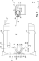
- a dispensing head 1 in particular for a distribution system (not shown) of a fluid product.
- the dispensing system comprises the dispensing head 1 and a sampling device (not shown) provided with a feed tube inserted into a well 2 located in the dispensing head 1.
- the dispensing head 1 comprises a body 3.
- the body 3 defines a bearing wall 4 situated on an upper part thereof.
- the support wall 4 allows the user to press the dispensing head 1 to spray product.
- the body 3 defines a housing 6.
- the housing 6 is in fluid communication with the well 2. This fluid communication is performed through an internal channel 27 made in the body 3.
- the body 3 comprises an anvil 8.
- the anvil 8 is manufactured in one piece with the dispensing head 1.
- the anvil 8 extends longitudinally along the axis X in the housing.
- the anvil 8 has a circular section in the plane ZY.
- the anvil 8 has a core 9 visible on the figures 1 and 3 .
- the core 9 is in the form of an X-axis protruding member of a distal surface of the anvil 8.
- the core 9 comprises a cylindrical portion 11.
- the cylindrical portion 11 is located at the base of the core and is adjacent to the distal surface of the turbulent anvil.
- the core 9 comprises a conical portion 12 of revolution about the axis X.
- the conical portion 12 extends from the cylindrical portion 11 and ends with a vertex 13.
- the vertex 13 is flat.
- the top 13 is in the form of a plane wall substantially perpendicular to the axis X.
- the cylindrical portion 11 and the conical portion 12 together form a peripheral wall 36 of the core 9.
- the dispensing head 1 comprises a spray nozzle 14.
- the spray nozzle 14 is an element attached to the dispensing head 1.
- the spray nozzle 14 has an annular wall forming an open volume on one side and closed on the other by a distal wall.
- the spray nozzle 14 defines a central opening 17 laterally bordered along the Y and Z axes by the annular wall and longitudinally along the X axis by the distal wall 16.
- the annular wall comprises a locking tab 18.
- the locking lug 18 is in the form of a projecting annular rim extending along the perimeter of the annular wall.
- the distal wall 16 has a dispensing orifice 19 and a vortex chamber 20.
- the vortex chamber 20 opens into the dispensing orifice 19.
- the vortex chamber is rotated about the X axis.
- the vortex chamber 20 comprises a convergent portion 37.
- Said Swirl chamber 20 includes an inner wall 35 and extends from an upstream end 21 coinciding with an inner surface 23 of the distal wall 16 to a downstream end 22.
- the downstream end 22 can be easily located by positioning in the dispensing orifice 19 and then moving along the X axis from an outer surface 24 of the distal wall 16.
- the dispensing orifice 19 is a cylinder of revolution, and the section thereof is substantially constant. Where the section begins to vary is the boundary between the dispensing orifice 19 and the vortex chamber 20 ie the downstream end.
- downstream end 22 of the vortex chamber 20 is the dispensing orifice 19.
- the dispensing orifice 19 coincides with the downstream end 22.
- the vortex chamber 20 further comprises a prechamber 50, located upstream of the convergent portion 37 of said vortex chamber.
- Said pre-chamber 50 is here annular. It is delimited by the cylindrical portion 11 of the core 9, the part facing the distal wall 16 of the nozzle, the distal surface 10 of the anvil and the convergent portion 37 of the vortex chamber.
- the upstream end of the chamber 20 corresponds to the upstream end of the prechamber 50.
- the dispensing nozzle 14 has at least one supply channel for the vortex chamber 20.
- the dispensing nozzle 14 comprises two feed channels.
- the supply channels are made in the distal wall.
- the supply channels open tangentially into the annular prechamber 50 belonging to the vortex chamber 20. They could lead in any other direction. In particular, the channels 25 could emerge in a direction tangential to the first step 30, immediately downstream of the prechamber 50.
- the prechamber 50 allows the rotation of the product around the cylindrical portion 11 of the core 9.
- the prechamber 50 annular has a length measured along the axis X equal to a depth of the supply channels measured along the axis X.
- the pre-chamber 50 annular is not a step in the sense given in the invention.
- the spray nozzle 14 is a separate element attached to the dispensing head 1. More specifically, the spraying nozzle 14 is inserted into the housing 6 and fixed to the body 3 by virtue of the locking tab 18 embedded in said body 3.
- the anvil 8 is arranged in part in the central opening 17 of the nozzle so that the distal surface abuts on the inner surface 23.
- the core 9 then lodges inside the vortex chamber 20.
- the peripheral wall 36 of the core 9 and the convergent portion 37 of the swirl chamber 20 form a fluid path in which the product from the supply channel flows.
- a step 30 is defined by a transverse wall 31 and a longitudinal wall 32.
- the transverse wall 31 extends in a plane intersecting with the axis X. Indeed by extending the transverse wall 31 in the direction of the axis X by means of an imaginary line on the figure 1 , the latter crosses the axis X.
- the longitudinal wall 32 is substantially parallel to the axis X. By extending the longitudinal wall 32 on either side at infinity with an imaginary line, it is substantially parallel to the X axis.
- the steps 30 form obstacles in the fluidic path. More specifically, the transverse walls 31 of the steps 30 form obstacles in the fluidic path.
- the combination of the steps 30 and a core 9 which extends into the vortex chamber 20 eliminates the continuous jet which appears in a central zone 28 of a cone 29 of sprayed droplets at the outlet of the orifice 19 of distribution.
- the combination of the core 9 and the steps 30 forming obstacles in the fluidic path advantageously makes it possible to obtain in the central zone 28 droplets of identical or similar size, to the droplets present in the rest of the cone. sprayed.
- the dimensions of the droplets in the cone 29 are substantially uniform.
- the transverse walls 31 are substantially orthogonal to the axis X. The impact with the product in the fluidic path is then abrupt in favor of a better impaction of the product on the steps 30.
- the transverse walls 31 are not orthogonal. In the latter case the impact energy between the product and the transverse walls is lower. The energy of the impact of the product against the steps 30 can be adjusted by changing the angle formed by the transverse walls with the X axis.
- Each transverse wall 31 crosses at each of its ends a longitudinal wall 32.
- these crossings are referred to as nosing 33 and walking recess 34 as a function of their distance in the plane ZY of the peripheral wall 36 of the core 9.
- the nosing 33 is located at a proximal distance between 70 and 250 micrometers of the peripheral wall of the core 9. figure 1 this proximal distance is measured along an imaginary straight line drawn from the walking nose 33 to the peripheral wall 36 along the shortest route. Preferably the proximal distance is about 160 micrometers.
- the proximal distance included in the range mentioned above and more particularly the specified value allow shear sufficient product in the vicinity of the nosing 33 against the peripheral wall wall of the core 9. This results in a localized increase in the rate shear induced by the wall 36 device in the vicinity of the noses 33 of walking to reduce the viscosity of the product. In other words, this makes it possible to thin the product.
- the convergent portion 37 of the vortex chamber 20 comprises between three and fifteen steps 30 and preferably four steps 30.
- the convergent portion 37 preferably comprises four transverse walls 31 and four walls 32 longitudinal. This makes it possible to obtain significant results with a total or almost total elimination of a continuous jet in the central zone.
- the core 9 is arranged inside the swirl chamber 20 so that any point of the plane wall is at a predetermined distance from the downstream end of between 100 and 300 micrometers, and preferably about 200 micrometers. .
- This distance is particularly advantageous because it allows an optimal evacuation of the product in that the product is both properly fluidified on the one hand and limit the pressure drop when circulating in the fluid path.
- the core 9 and more precisely the plane wall is arranged facing the dispensing orifice 19 so that said core defines an obstacle to any intrusion from the external environment by the dispensing orifice 19 so as not to plug the ducts. .
- the core 9 of the anvil 8 is full.
- the core 9 does not include any orifice emerging for example on the external medium on the one hand and on the vortex chamber 20 on the other hand or on any part of the housing 6.
- the dispensing orifice 19 is only fluidly connected to the convergent portion 37.
- the dispensing nozzle 14 does not include any channel or outlet connecting the vortex chamber 20 or the housing 6 to the external medium, for example when it is mounted on the body 3.
- the steps can be arranged by angular sector.
- the steps extend in an interrupted manner on the perimeter of the convergent portion 37 of the vortex chamber 20 and / or the peripheral wall 36 of the core 9.
- the core 9 and / or the swirl chamber 20 comprise at least two groups of steps separated by smooth walls.
- the invention also relates to a system for spraying a product comprising a dispensing head 1 as previously described.
Abstract
Description
- L'invention concerne un dispositif de pulvérisation, notamment pour un système de distribution d'un produit muni d'un bouton poussoir.
- Dans une application particulière, le système de distribution est destiné à équiper des flacons utilisés en parfumerie, en cosmétique ou pour des traitements pharmaceutiques. En effet, ce type de flacon contient un produit qui est restitué par le système de distribution comprenant un dispositif de prélèvement dudit produit, ledit système étant actionné par exemple par un bouton poussoir pour permettre la pulvérisation du produit. En général, le dispositif de prélèvement comprend une pompe ou une valve à actionnement manuel, par exemple par l'intermédiaire du bouton poussoir.
- De tels boutons poussoirs sont classiquement réalisés en au moins deux parties, dont un corps d'actionnement et une buse de pulvérisation qui sont assemblés l'un à l'autre. La buse comprend généralement une chambre tourbillonnaire pourvue d'un orifice de distribution, ainsi qu'au moins un canal d'alimentation de ladite chambre.
- Le dispositif de prélèvement prélève le produit du flacon par un tube plongeur, et le pousse à l'intérieur du conduit aménagé dans le poussoir, qui est l'élément d'actionnement du dispositif de prélèvement. Ce conduit débouche dans une chambre dite tourbillonnaire destinée à faire tourner très rapidement le liquide et donc à lui donner de la vitesse et les effets de la force centrifuge. Cette chambre tourbillonnaire est prolongée en son centre par un orifice de sortie par lequel le produit s'échappe à l'extérieur avec une forte vitesse. Mû par cette vitesse, et soumis aux forces centrifuges, le liquide se fractionne en gouttelettes et forme un aérosol. La taille des gouttelettes issues de la chambre tourbillonnaire dépend en partie de la force et de la vitesse avec laquelle l'utilisateur actionne la pompe en appuyant sur le bouton poussoir avec son doigt, car la pression induite en dépend.
- Afin d'assurer une bonne uniformité de la taille desdites gouttelettes, une technologie consiste à utiliser une chambre tourbillonnaire de révolution. Ainsi, le flot tourne dans la chambre sous forme de nappe qui s'impacte sur elle-même après sa sortie par l'orifice de distribution.
- Cette technologie est utilisée pour des produits non ou peu visqueux.
- Lorsque le produit est visqueux, typiquement de l'ordre de 50 ou 100 fois la viscosité de l'eau, l'impaction des nappes ne se produit pas correctement par exemple lorsque la viscosité est supérieure à 150 mPa.s. Il en résulte une taille trop importante des gouttelettes et le cône de produit pulvérisé est alors de mauvaise qualité.
- Afin d'améliorer le cône de produit pulvérisé, lorsque le produit est visqueux, une technologie consiste à ajouter des marches dans la chambre tourbillonnaire.
- Les marches permettent d'améliorer l'impaction des nappes de produit et d'obtenir des gouttelettes de petites dimensions, et ceci avec un produit visqueux.
- Bien que cette technologie améliore le cône pulvérisé, un inconvénient subsiste. En effet, les dimensions des gouttelettes conviennent dans la majeure partie du cône pulvérisé ce qui permet d'obtenir un cône de gouttelettes fines de produit. Toutefois, une zone centrale du cône ne présente pas les exigences requises. Cette zone centrale se situe immédiatement en aval de l'orifice de distribution dans le sens de déplacement du produit, et s'étend de manière sensiblement rectiligne. Dans cette zone centrale, les gouttelettes ont des dimensions bien plus élevées que dans le reste du cône. Il est fréquent qu'un jet continu dans une zone centrale coexiste avec les gouttelettes périphériques. En d'autres termes, les dimensions des gouttelettes ne sont pas uniformes dans le cône.
- Un utilisateur reçoit alors sur ses mains ou une autre partie de son corps, du produit sous la forme d'un jet continu dans la zone centrale, et ceci dans un cône de gouttelettes fines. L'expérience du produit est par conséquent altérée. Ceci est d'autant plus vrai chez une clientèle dont les attentes sont souvent élevées. Outre la sensation désagréable que procure le jet continu, ceci renvoie une image déplorable du produit et de son fabricant en dépit des qualités cosmétiques qu'il recèle.
- L'invention vise à résoudre cet inconvénient.
- A cette fin, l'invention vise une tête de distribution, notamment pour un système de distribution d'un produit dans laquelle la tête comprend :
- une buse de pulvérisation comprenant un orifice de distribution et une chambre tourbillonnaire débouchant dans l'orifice de distribution, la chambre tourbillonnaire comprenant une partie convergente, ladite chambre tourbillonnaire s'étendant suivant un axe, entre une extrémité amont et une extrémité aval dans le sens de déplacement du produit,
- une enclume comprenant un noyau muni d'une paroi périphérique, le noyau logeant à l'intérieur de la chambre tourbillonnaire, la paroi périphérique et la partie convergente formant au moins un chemin fluidique dans lequel circule le produit,
- la partie convergente comprenant une paroi intérieure de la buse, ladite paroi intérieure et/ou la paroi périphérique du noyau est munie d'une pluralité de marches, chaque marche étant définie par une paroi transversale qui s'étend dans un plan sécant à l'axe et une paroi longitudinale sensiblement parallèle à l'axe, les marches formant des obstacles dans le chemin fluidique.
- Cette tête de distribution présente l'avantage d'éliminer le jet continu qui apparaît dans la zone centrale. Ceci est rendu possible par l'action combinée de la partie convergente munie de marches et d'un noyau formant au moins un chemin fluidique dans lequel le produit rencontre des obstacles. Ceci est aussi rendu possible par l'action combinée de la partie convergente et d'un noyau muni de marche ainsi que d'une partie convergente et d'un noyau, tous deux, munis de marches. La tête de distribution est particulièrement avantageuse lorsque le produit présente un comportement rhéologique non newtonien rhéofluidifiant. Ce type de fluide se fluidifie selon que le taux de cisaillement augmente. Ce type de produit est largement utilisé dans l'industrie cosmétique. La zone centrale comprend alors des gouttelettes dont les dimensions sont sensiblement identiques dans tout le cône.
- Selon différents modes de réalisation de l'invention, qui pourront être pris ensemble ou séparément :
- la partie convergente comprend au moins un nez de marche situé à la jonction entre une paroi transversale et une paroi longitudinale, le nez de marche étant situé à une distance proximale comprise entre 70 et 250 micromètres de la paroi périphérique du noyau mesurée selon une droite imaginaire tracée depuis le nez de marche jusqu'à la paroi périphérique selon l'itinéraire le plus court ;
- une longueur de la paroi longitudinale est comprise entre 30 et 250 micromètres mesurée selon l'axe ;
- une longueur de la paroi transversale est comprise entre 30 et 350 micromètres mesurée selon un axe orthogonal à l'axe ;
- les marches s'étendent depuis l'extrémité amont jusqu'à l'extrémité aval ;
- la partie convergente comprend entre trois et quinze marches, de préférence quatre marches ;
- la chambre tourbillonnaire comprend une préchambre en amont de ladite partie convergente ;
- la buse comprend au moins un canal d'alimentation de la chambre tourbillonnaire ;
- le ou les canaux débouchent dans la préchambre ;
- la préchambre est annulaire ;
- la hauteur du ou des canaux correspond à la hauteur de la préchambre ;
- le ou les canaux débouchent tangentiellement dans la chambre tourbillonnaire ;
- le noyau comprend une portion conique de révolution autour de l'axe et définit un sommet situé en regard de l'orifice de distribution ;
- le sommet est plat et comprend une paroi plane sensiblement perpendiculaire à l'axe ;
- le noyau est plein ;
- l'orifice de distribution est uniquement relié de manière fluidique à la partie convergente de la buse.
- L'invention concerne également un système de distribution d'un produit comprenant une tête de distribution tel que précédemment décrit.
- L'invention sera mieux comprise à la lumière de la description suivante qui n'est donnée qu'à titre indicatif et qui n'a pas pour but de la limiter, accompagnée des dessins joints dans lesquels :
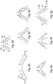
- la
figure 1 est une vue en coupe en deux dimensions d'une tête de distribution selon l'invention ; - la
figure 2 est une vue en coupe et en perspective d'une buse de distribution de la tête de distribution de lafigure 1 ; - la
figure 3 est une vue en perspective de la tête de distribution de lafigure 1 sans la buse de distribution ; - la
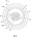
figure 4 est une vue en deux dimension de la buse de distribution desfigures 1 et2 ; - la
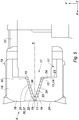
figure 5 est une vue similaire à lafigure 1 d'un deuxième mode de réalisation ; - la
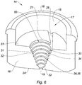
figure 6 est une vue similaire à lafigure 2 du deuxième mode de réalisation de lafigure 5 ; - la
figure 7 est une vue similaire à lafigure 3 du deuxième mode de réalisation ; - les
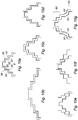
figures 8a, 8b, 8c, 8d, 8e, 8f, 8g illustrent schématiquement des variantes de réalisation dans lesquelles la buse comprend des marches ; - les
figures 9a, 9b, 9c ,8d ,9e, 9f, 9g illustrent schématiquement des variantes de réalisation dans lesquelles un noyau comprend des marches ; - les
figures 10a, 10b, 10c, 10d, 10e, 10f, 10g illustrent schématiquement des variantes de réalisation dans lesquelles la buse et le noyau comprennent des marches. - Sur la
figure 1 est représentée une tête 1 de distribution notamment pour un système de distribution (non représenté) d'un produit fluide. - Le système de distribution comprend la tête 1 de distribution et un dispositif de prélèvement (non représenté) muni d'un tube d'amenée inséré dans un puits 2 situé dans la tête 1 de distribution.
- Dans la suite de la description, on adoptera par convention le repère orthogonal direct défini comme suit :
- un axe X définissant une première direction, qui correspond à l'axe d'une chambre tourbillonnaire de la tête 1 de distribution,
- un axe Y orthogonal à l'axe X et définissant une deuxième direction ainsi qu'un plan XY,
- un axe Z à la fois orthogonal à l'axe Y et à l'axe X et définissant une troisième direction ainsi que des plans ZY et ZX.
- La tête 1 de distribution comprend un corps 3. Le corps 3 définit une paroi 4 d'appui située sur une partie supérieure de celui-ci. La paroi 4 d'appui permet à l'utilisateur de presser la tête 1 de distribution pour pulvériser du produit.
- Ainsi qu'illustré sur la
figure 3 , le corps 3 définit un logement 6. Le logement 6 est en communication fluidique avec le puits 2. Cette communication fluidique est réalisée par le biais d'un canal 27 interne pratiqué dans le corps 3. - Le corps 3 comprend une enclume 8. De préférence, l'enclume 8 est fabriquée d'un seul tenant avec la tête 1 de distribution. L'enclume 8 s'étend longitudinalement selon l'axe X dans le logement. L'enclume 8 présente une section circulaire dans le plan ZY.
- L'enclume 8 comporte un noyau 9 visible sur les
figures 1 et3 . Le noyau 9 se présente sous la forme d'un élément faisant saillie selon l'axe X d'une surface 10 distale de l'enclume 8. - Le noyau 9 comprend une portion 11 cylindrique. La portion 11 cylindrique est située à la base du noyau et est adjacente à la surface 10 distale de l'enclume 8.tourbillonnaire. Le noyau 9 comprend une portion 12 conique de révolution autour de l'axe X. La portion 12 conique s'étend depuis la portion 11 cylindrique et se termine par un sommet 13. Le sommet 13 est plat. Le sommet 13 se présente sous la forme d'une paroi plane sensiblement perpendiculaire à l'axe X.
- La portion 11 cylindrique et la portion 12 conique forment ensemble une paroi 36 périphérique du noyau 9.
- La tête 1 de distribution comprend une buse 14 de pulvérisation. La buse 14 de pulvérisation est un élément rapporté sur la tête 1 de distribution. La buse 14 de pulvérisation comporte une paroi 15 annulaire formant un volume ouvert d'un côté et fermé de l'autre par une paroi 16 distale. La buse 14 de pulvérisation définit une ouverture 17 centrale bordée latéralement selon les axes Y et Z par la paroi 15 annulaire et longitudinalement selon l'axe X par la paroi 16 distale. La paroi 15 annulaire comprend une patte 18 de verrouillage. La patte 18 de verrouillage se présente sous la forme d'une bordure annulaire en saillie, qui s'étend le long du périmètre de la paroi 15 annulaire.
- La paroi 16 distale comporte un orifice 19 de distribution et une chambre 20 tourbillonnaire. La chambre 20 tourbillonnaire débouche dans l'orifice 19 de distribution. La chambre 20 tourbillonnaire est de révolution autour de l'axe X. De manière plus précise, la chambre 20 tourbillonnaire comprend une partie convergente 37. Ladite chambre tourbillonnaire 20 comprend une paroi 35 intérieure et s'étend depuis une extrémité 21 amont coïncidant avec une surface 23 intérieure de la paroi 16 distale jusqu'à une extrémité 22 aval. L'extrémité 22 aval peut être localisée aisément en se positionnant dans l'orifice 19 de distribution puis en se déplaçant selon l'axe X à partir d'une surface 24 extérieure de la paroi 16 distale. L'orifice 19 de distribution est un cylindre de révolution, ainsi la section de celui-ci est sensiblement constante. L'endroit où la section commence à varier est la frontière entre l'orifice 19 de distribution et la chambre 20 tourbillonnaire à savoir l'extrémité 22 aval.
- Dans une variante de réalisation non représentée, l'extrémité 22 aval de la chambre 20 tourbillonnaire est l'orifice 19 de distribution. En d'autres termes, l'orifice 19 de distribution coïncide avec l'extrémité 22 aval.
- Dans une variante de réalisation non représentée sur les figures, seule une partie de la chambre 20 tourbillonnaire est de révolution.
- Dans le mode de réalisation illustré, la chambre tourbillonnaire 20 comprend en outre une préchambre 50, située en amont de la partie convergente 37 de ladite chambre tourbillonnaire. Ladite préchambre 50 est ici annulaire. Elle est délimitée par la portion 11 cylindrique du noyau 9, la partie en regard de la paroi distale 16 de la buse, la surface distale 10 de l'enclume et la partie convergente 37 de la chambre tourbillonnaire. Ainsi, l'extrémité amont de la chambre 20 correspond à l'extrémité amont de la préchambre 50.
- La buse 14 de distribution comporte au moins un canal 25 d'alimentation de la chambre 20 tourbillonnaire. Dans le mode préféré de réalisation illustré sur les figures, la buse 14 de distribution comprend deux canaux 25 d'alimentation. Les canaux 25 d'alimentation sont pratiqués dans la paroi 16 distale.
- Les canaux 25 d'alimentation débouchent tangentiellement dans la préchambre 50 annulaire appartenant à la chambre 20 tourbillonnaire. Ils pourraient déboucher selon toute autre orientation. En particulier, les canaux 25 pourraient déboucher selon une direction tangentielle à la première marche 30, immédiatement en aval de la préchambre 50. La préchambre 50 permet la mise en rotation du produit autour de la portion 11 cylindrique du noyau 9. La préchambre 50 annulaire présente une longueur mesurée selon l'axe X égale à une profondeur des canaux 25 d'alimentation mesurée selon l'axe X. La préchambre 50 annulaire n'est pas une marche au sens donné dans l'invention.
- Ainsi que précédemment évoqué la buse 14 de pulvérisation est un élément distinct rapporté sur la tête 1 de distribution. De façon plus précise, la buse 14 de pulvérisation est insérée dans le logement 6 et fixée au corps 3 grâce à la patte 18 de verrouillage encastrée dans ledit corps 3.
- Ainsi qu'illustré sur la
figure 1 , l'enclume 8 est agencée en partie dans l'ouverture 17 centrale de la buse de sorte que la surface 10 distale soit en butée sur la surface 23 intérieure. Le noyau 9 loge alors à l'intérieur de la chambre 20 tourbillonnaire. La paroi 36 périphérique du noyau 9 et la partie 37 convergente de la chambre 20 tourbillonnaire forment un chemin fluidique dans lequel circule le produit provenant du canal 25 d'alimentation. - Ainsi qu'on peut le voir sur les
figures 1 et2 , la partie 37 convergente de la chambre 20 tourbillonnaire comporte une pluralité de marches 30. Une marche 30 est définie par une paroi 31 transversale et une paroi 32 longitudinale. - La paroi 31 transversale s'étend dans un plan sécant à l'axe X. En effet en prolongeant la paroi 31 transversale en direction de l'axe X à l'aide d'une droite imaginaire sur la
figure 1 , cette dernière coupe l'axe X. La paroi 32 longitudinale est sensiblement parallèle à l'axe X. En prolongeant la paroi 32 longitudinale de part et d'autre à l'infini avec une droite imaginaire, celle-ci est sensiblement parallèle à l'axe X. - Dans cette configuration, les marches 30 forment des obstacles dans le chemin fluidique. De manière plus précise, les parois 31 transversales des marches 30 forment des obstacles dans le chemin fluidique.
- La combinaison des marches 30 et d'un noyau 9 qui s'étend dans la chambre 20 tourbillonnaire permet d'éliminer le jet continu qui apparaît dans une zone 28 centrale d'un cône 29 de gouttelettes pulvérisé à la sortie de l'orifice 19 de distribution. En d'autres termes, la combinaison du noyau 9 et des marches 30 formant des obstacles dans le chemin fluidique permet avantageusement d'obtenir dans la zone 28 centrale des gouttelettes ayant des dimensions identiques sinon similaires, aux gouttelettes présentes dans le reste du cône 29 pulvérisé. Ainsi les dimensions des gouttelettes dans le cône 29 sont sensiblement uniformes.
- Dans un mode de réalisation préféré de l'invention, les parois 31 transversales sont sensiblement orthogonales à l'axe X. Le choc avec le produit dans le chemin fluidique est alors brutal au profit d'une meilleure impaction du produit sur les marches 30.
- Dans une variante de réalisation non représentée, les parois 31 transversales ne sont pas orthogonales. Dans ce dernier cas l'énergie du choc entre le produit et les parois 31 transversales est moins élevée. L'énergie du choc du produit contre les marches 30 peut être ajustée en modifiant l'angle que forment les parois 31 transversales avec l'axe X.
- Chaque paroi 31 transversale croise à chacune de ses extrémités une paroi 32 longitudinale. Dans ce qui suit, ces croisements sont dénommés nez 33 de marche et creux 34 de marche en fonction de leur éloignement dans le plan ZY de la paroi 36 périphérique du noyau 9.
- Dans un mode préféré de réalisation, le nez 33 de marche se situe à une distance proximale comprise entre 70 et 250 micromètres de la paroi 36 périphérique du noyau 9. Sur la
figure 1 , cette distance proximale est mesurée selon une droite imaginaire tracée depuis le nez 33 de marche jusqu'à la paroi 36 périphérique selon l'itinéraire le plus court. De préférence la distance proximale est d'environ 160 micromètres. - La distance proximale comprise dans l'intervalle évoqué ci-dessus et plus particulièrement la valeur spécifique indiquée, permettent un cisaillement du produit suffisant au voisinage des nez 33 de marche contre la paroi 36 périphérique du noyau 9. Il en résulte une augmentation localisée du taux de cisaillement induit par la paroi 36 périphérique au voisinage des nez 33 de marche permettant de diminuer la viscosité du produit. En d'autres termes, ceci permet de fluidifier le produit.
- Il a été déterminé qu'une longueur comprise entre 30 et 350 micromètres pour la paroi 31 transversale mesurée selon l'axe Y sur la
figure 1 et dans le plan ZY en perspective, est particulièrement efficace. Il a également été déterminé qu'une longueur comprise entre 30 et 250 micromètres pour la paroi 32 longitudinale selon l'axe X sur lafigure 1 et dans le plan ZX en perspective est particulièrement efficace. - Dans un mode préféré de réalisation représenté sur les figures, la partie 37 convergente de la chambre 20 tourbillonnaire comporte entre trois et quinze marches 30 et de préférence quatre marches 30. Ainsi la partie 37 convergente comporte de préférence quatre parois 31 transversales et quatre parois 32 longitudinales. Ceci permet d'obtenir des résultats significatifs avec une élimination totale sinon quasi-totale d'un jet continu dans la zone 28 centrale.
- Avantageusement, le noyau 9 est agencé à l'intérieur de la chambre 20 tourbillonnaire de sorte que tout point de la paroi plane se situe à une distance prédéterminée de l'extrémité aval comprise entre 100 et 300 micromètres, et de préférence à environ 200 micromètres. Cette distance est particulièrement avantageuse car elle permet une évacuation optimale du produit en ce sens que le produit est à la fois correctement fluidifié d'une part et limite la perte de charge lorsque circule dans le chemin fluidique.
- Le noyau 9 et plus précisément la paroi plane est agencée en regard de l'orifice 19 de distribution de sorte que ledit noyau définit un obstacle à toute intrusion depuis le milieu extérieur par l'orifice 19 de distribution de sorte à ne pas boucher les conduits.
- Avantageusement le noyau 9 de l'enclume 8 est plein. En d'autres termes le noyau 9 ne comprend aucun orifice quelconque débouchant par exemple sur le milieu extérieur d'une part et sur la chambre 20 tourbillonnaire d'autre part ou sur une quelconque partie du logement 6.
- Avantageusement l'orifice 19 de distribution est uniquement relié de manière fluidique à la partie 37 convergente. En d'autres termes la buse 14 de distribution ne comprend aucun canal ou sortie reliant la chambre 20 tourbillonnaire ou le logement 6 au milieu extérieur par exemple lorsqu'elle est montée sur le corps 3.
- Ceci permet avantageusement de maintenir les conditions propices de pression dans la chambre 20 tourbillonnaire et plus globalement dans le logement 6 d'une part et d'éviter tout contamination bactérienne avec le milieu extérieur d'autre part.
- Dans une variante de réalisation représentée sur les
figures 5 à 7 , la chambre 20 tourbillonnaire est plus longue selon l'axe X que celle du mode de réalisation représenté sur lesfigures 1 à 4 . - Les
figures 8a à 8g illustrent des modes de réalisation dans lesquels les marches sont agencées sur la buse. - Les
figures 9a à 9g illustrent des modes de réalisation dans lesquels les marches sont agencées sur le noyau. - Les
figures 10a à 10g illustrent des modes de réalisation dans lesquels les marches sont agencées sur la buse et sur le noyau. - Les
figures 8a ,9a et10a illustrent des variantes dans lesquelles parois longitudinales et transversales sont approximativement de même dimension. - Les
figures 8b ,9b et10b illustrent des variantes dans lesquelles parois longitudinales et transversales sont de dimensions différentes. - Les
figures 8c ,9c et10c illustrent des variantes dans lesquelles la paroi longitudinale située la plus en aval selon le déplacement du fluide est plus longue que les autres parois longitudinales situées plus en amont. - Les
figures 8d ,9d et10d illustrent des variantes dans lesquelles une paroi longitudinale quelconque est plus longue que les autres parois longitudinales. - Les
figures 8e ,9e et10e illustrent des variantes dans lesquelles le chemin fluidique est divergent. - Les
figures 8f ,9f et10f illustrent des variantes dans lesquelles le chemin fluidique est convergent. Cette variante est particulièrement intéressante car elle permet un taux de cisaillement croissant dans le sens amont - aval selon le déplacement du produit. - Les
figures 8g ,9g et10g illustrent des variantes dans lesquelles une section intermédiaire 51 plane sépare deux groupes de marches 53. - Dans une variante de réalisation non représentée sur les figures, les marches peuvent être agencées par secteur angulaire. En d'autres termes, les marches s'étendent de manière interrompue sur le périmètre de la partie 37 convergente de la chambre 20 tourbillonnaire et/ou de la paroi 36 périphérique du noyau 9. Dans cette variante, le noyau 9 et/ou la chambre 20 tourbillonnaire comprennent au moins deux groupes de marches séparés par des parois lisses.
- L'invention vise également un système de pulvérisation d'un produit comprenant une tête 1 de distribution tel que précédemment décrit.
Claims (14)
- Tête (1) de distribution, notamment pour un système de distribution d'un produit caractérisé en ce que la tête (1) comprend :- une buse (14) de pulvérisation comprenant un orifice (19) de distribution et une chambre (20) tourbillonnaire débouchant dans l'orifice (19) de distribution, la chambre (20) tourbillonnaire comprenant une partie (37) convergente, ladite chambre tourbillonnaire s'étendant suivant un axe (X) entre une extrémité (21) amont et une extrémité (22) aval dans le sens de déplacement du produit, et- une enclume (8) comprenant un noyau (9) muni d'une paroi (36) périphérique, le noyau (9) logeant à l'intérieur de la chambre (20) tourbillonnaire, la paroi (36) périphérique et la partie (37) convergente formant au moins un chemin fluidique dans lequel circule le produit,la partie (37) convergente comprenant une paroi (35) intérieure de la buse (14), ladite paroi (35) intérieure et/ou la paroi (36) périphérique du noyau étant munie(s) d'une pluralité de marches (30), chaque marche (30) étant définie par une paroi (31) transversale qui s'étend dans un plan sécant à l'axe (X) et une paroi (32) longitudinale sensiblement parallèle à l'axe, les marches (30) formant des obstacles dans le chemin fluidique, la buse (14) comprend au moins un canal (25) d'alimentation de la chambre (20) tourbillonnaire débouchant tangentiellement dans la chambre tourbillonnaire (20)..
- Tête (1) de distribution selon la revendication 1 dans laquelle la partie (37) convergente comprend au moins un nez (33) de marche situé à la jonction entre une paroi (31) transversale et une paroi (32) longitudinale, le nez (33) de marche étant situé à une distance proximale comprise entre 70 et 250 micromètres de la paroi (36) périphérique du noyau (9) mesurée selon une droite imaginaire tracée depuis le nez (33) de marche jusqu'à la paroi (36) périphérique selon l'itinéraire le plus court.
- Tête (1) de distribution selon la revendication 2 dans laquelle une longueur de la paroi (32) longitudinale est comprise entre 30 et 250 micromètres mesurée selon l'axe (X).
- Tête (1) de distribution selon la revendication 2 ou 3 dans laquelle une longueur de la paroi (31) transversale est comprise entre 30 et 350 micromètres mesurée selon un axe orthogonal à l'axe (X).
- Tête (1) de distribution selon l'une des revendications précédentes dans laquelle les marches (30) s'étendent depuis l'extrémité (21) amont jusqu'à l'extrémité (22) aval.
- Tête (1) de distribution selon l'une des revendications précédentes dans laquelle la partie (37) convergente comprend entre trois et quinze marches (30), de préférence quatre marches (30).
- Tête de distribution selon la revendication précédente caractérisée en ce que la chambre tourbillonnaire (20) comprend une préchambre en amont de ladite partie convergente (37), le ou les canaux (25) débouchant dans la préchambre (50).
- Tête de distribution selon la revendication précédente caractérisée en ce que la préchambre (50) est annulaire.
- Tête de distribution selon l'une des revendications 7 et 8 caractérisée en ce que la hauteur du ou des canaux (25) correspond à la hauteur de la préchambre (50).
- Tête (1) de distribution selon l'une des revendications précédentes dans laquelle le noyau (9) comprend une portion (12) conique de révolution autour de l'axe (X) et définissant un sommet (13) situé en regard de l'orifice (19) de distribution.
- Tête (1) de distribution selon la revendication 10 dans laquelle le sommet (13) est plat et comprend une paroi plane sensiblement perpendiculaire à l'axe (X).
- Tête (1) de distribution selon l'une des revendications précédentes dans laquelle le noyau (9) est plein.
- Tête (1) de distribution selon l'une des revendications précédentes dans laquelle l'orifice (19) de distribution est uniquement relié de manière fluidique à la partie (37) convergente de la buse.
- Système de distribution d'un produit caractérisé en ce que celui-ci comprend une tête (1) de distribution selon l'une des revendications précédentes.
Applications Claiming Priority (1)
| Application Number | Priority Date | Filing Date | Title |
|---|---|---|---|
| FR1851712A FR3078271B1 (fr) | 2018-02-27 | 2018-02-27 | Tete de distribution a chambre tourbillonnaire etagee pour un systeme de distribution |
Publications (2)
| Publication Number | Publication Date |
|---|---|
| EP3530355A1 true EP3530355A1 (fr) | 2019-08-28 |
| EP3530355B1 EP3530355B1 (fr) | 2021-07-21 |
Family
ID=62143374
Family Applications (1)
| Application Number | Title | Priority Date | Filing Date |
|---|---|---|---|
| EP19157320.3A Active EP3530355B1 (fr) | 2018-02-27 | 2019-02-14 | Tête de distribution à chambre tourbillonnaire étagée pour un système de distribution |
Country Status (4)
| Country | Link |
|---|---|
| US (1) | US11033913B2 (fr) |
| EP (1) | EP3530355B1 (fr) |
| CN (1) | CN110193432B (fr) |
| FR (1) | FR3078271B1 (fr) |
Families Citing this family (1)
| Publication number | Priority date | Publication date | Assignee | Title |
|---|---|---|---|---|
| US11794984B2 (en) * | 2019-10-15 | 2023-10-24 | Aptargroup, Inc. | Actuator for dispensing a fluent product |
Citations (4)
| Publication number | Priority date | Publication date | Assignee | Title |
|---|---|---|---|---|
| DE102007025214A1 (de) * | 2006-06-21 | 2008-02-14 | Afros S.P.A. | Verfahren und Vorrichtung zum Hochdruckmischen von chemisch reaktiven Fluidkomponenten |
| EP2295150A2 (fr) * | 2009-09-10 | 2011-03-16 | Rexam Dispensing Systems | Bouton poussoir pour un système de distribution d'un produit sous pression |
| EP2452780A2 (fr) * | 2010-11-12 | 2012-05-16 | Dental Care Innovation GmbH | Système pour nettoyer les dents |
| EP3231516A1 (fr) * | 2016-04-14 | 2017-10-18 | Albéa le Tréport | Buse de pulverisation, notamment pour un systeme de distribution d'un produit sous pression muni d'un bouton poussoir, et systeme de distribution comprenant une telle buse |
Family Cites Families (8)
| Publication number | Priority date | Publication date | Assignee | Title |
|---|---|---|---|---|
| US3129893A (en) * | 1962-05-31 | 1964-04-21 | Edward Howard Green | Spray head for swirling spray |
| US3881658A (en) * | 1971-06-03 | 1975-05-06 | Seaquist Valve Co | Mechanical breakup button or actuator |
| US3994442A (en) * | 1975-04-07 | 1976-11-30 | Seaquist Valve Company, Div. Of Pittway Corporation | Solid pattern mbu button |
| US5855322A (en) * | 1997-09-10 | 1999-01-05 | Py; Daniel | System and method for one-way spray aerosol tip |
| CN101218036B (zh) * | 2005-07-06 | 2011-05-04 | 三谷阀门有限公司 | 内容物排放机构和配备有该机构的气雾剂型产品和泵型产品 |
| FR2904573B1 (fr) * | 2006-08-04 | 2008-12-05 | Rexam Dispensing Systems Sas | Buse de pulverisation, organe de distribution comprenant une telle buse, distributeur comprenant un tel organe de distribution et utilisation d'une telle buse. |
| DE102010051227A1 (de) * | 2010-11-12 | 2012-05-16 | Dental Care Innovation Gmbh | Düse zur Abstrahlung von flüssigen Reinigungsmitteln mit darin dispergierten abrasiven Partikeln |
| US9604773B2 (en) * | 2015-01-20 | 2017-03-28 | Summit Packaging Systems, Inc. | Insert with nozzle formed by micro stepped and conical surfaces |
-
2018
- 2018-02-27 FR FR1851712A patent/FR3078271B1/fr active Active
-
2019
- 2019-02-14 EP EP19157320.3A patent/EP3530355B1/fr active Active
- 2019-02-25 CN CN201910136192.1A patent/CN110193432B/zh active Active
- 2019-02-27 US US16/288,011 patent/US11033913B2/en active Active
Patent Citations (4)
| Publication number | Priority date | Publication date | Assignee | Title |
|---|---|---|---|---|
| DE102007025214A1 (de) * | 2006-06-21 | 2008-02-14 | Afros S.P.A. | Verfahren und Vorrichtung zum Hochdruckmischen von chemisch reaktiven Fluidkomponenten |
| EP2295150A2 (fr) * | 2009-09-10 | 2011-03-16 | Rexam Dispensing Systems | Bouton poussoir pour un système de distribution d'un produit sous pression |
| EP2452780A2 (fr) * | 2010-11-12 | 2012-05-16 | Dental Care Innovation GmbH | Système pour nettoyer les dents |
| EP3231516A1 (fr) * | 2016-04-14 | 2017-10-18 | Albéa le Tréport | Buse de pulverisation, notamment pour un systeme de distribution d'un produit sous pression muni d'un bouton poussoir, et systeme de distribution comprenant une telle buse |
Also Published As
| Publication number | Publication date |
|---|---|
| US20190262847A1 (en) | 2019-08-29 |
| CN110193432A (zh) | 2019-09-03 |
| EP3530355B1 (fr) | 2021-07-21 |
| FR3078271A1 (fr) | 2019-08-30 |
| US11033913B2 (en) | 2021-06-15 |
| FR3078271B1 (fr) | 2022-08-05 |
| CN110193432B (zh) | 2022-06-07 |
Similar Documents
| Publication | Publication Date | Title |
|---|---|---|
| EP3231516B1 (fr) | Buse de pulverisation, notamment pour un systeme de distribution d'un produit sous pression muni d'un bouton poussoir, et systeme de distribution comprenant une telle buse | |
| EP2006025B1 (fr) | Buse de pulvérisation comprenant des rainures axiales d'alimentation équilibrée de la chambre tourbillonnaire | |
| EP2139604B1 (fr) | Organe de pulverisation, dispositif de projection comportant un tel organe, installation de projection et methode de nettoyage d'un tel organe | |
| EP1963023B1 (fr) | Dispositif de projection d'un liquide | |
| EP2496361B2 (fr) | Bouton poussoir pour un système de distribution d'un produit sous pression | |
| EP2429716B1 (fr) | Projecteur et organe de pulverisation de produit de revetement et procede de projection mettant en oeuvre un tel projecteur | |
| EP3296022B1 (fr) | Dispositif d'application | |
| EP1878507A2 (fr) | Dispositif de pulvérisation et utilisation de ce dispositif | |
| FR3074432A1 (fr) | Tete de distribution de produit fluide. | |
| WO1993023174A1 (fr) | Bouton-poussoir destine a etre monte sur une valve ou une pompe equipant un distributeur, et distributeur comportant un tel bouton-poussoir | |
| EP2892655B1 (fr) | Tete de pulverisation de produit fluide et distributeur comprenant une telle tete de pulverisation. | |
| EP3530355B1 (fr) | Tête de distribution à chambre tourbillonnaire étagée pour un système de distribution | |
| EP1883478B1 (fr) | Buse a chambre tourbillonnaire | |
| EP1467818A1 (fr) | Buse de pulverisation a diametre reduit | |
| EP2606980B1 (fr) | Bouton poussoir pour un système de distribution d'un produit sous pression | |
| WO2019106319A1 (fr) | Tête de distribution de produit fluide | |
| EP2119508B1 (fr) | Bouton poussoir à canaux de distribution convergents | |
| EP3479906A1 (fr) | Buse de pulvérisation avec rétrécissement de pré-atomisation, et tête de pulvérisation et dispositif de pulvérisation comprenant une telle buse | |
| WO2021156573A1 (fr) | Buse de pulvérisation de liquide sous forme de brouillard | |
| EP2233211A1 (fr) | Bouton poussoir pour un système de distribution d'un liquide sous pression | |
| EP2353726B1 (fr) | Bouton poussoir pour un système de distribution d'un produit sous pression | |
| FR2927551A1 (fr) | Buse de pulverisation a amenee non tangentielle, organe de distribution comprenant une telle buse,distributeur comprenant un tel organe et utilisation d'une telle buse | |
| WO2023111470A1 (fr) | Tete de pulverisation | |
| WO2018041594A1 (fr) | Tête de distribution d'un fluide sous pression et bombe aérosol ou pompe à actionnement manuel comprenant une telle tête de distribution | |
| BE558890A (fr) |
Legal Events
| Date | Code | Title | Description |
|---|---|---|---|
| PUAI | Public reference made under article 153(3) epc to a published international application that has entered the european phase |
Free format text: ORIGINAL CODE: 0009012 |
|
| STAA | Information on the status of an ep patent application or granted ep patent |
Free format text: STATUS: THE APPLICATION HAS BEEN PUBLISHED |
|
| AK | Designated contracting states |
Kind code of ref document: A1 Designated state(s): AL AT BE BG CH CY CZ DE DK EE ES FI FR GB GR HR HU IE IS IT LI LT LU LV MC MK MT NL NO PL PT RO RS SE SI SK SM TR |
|
| AX | Request for extension of the european patent |
Extension state: BA ME |
|
| STAA | Information on the status of an ep patent application or granted ep patent |
Free format text: STATUS: REQUEST FOR EXAMINATION WAS MADE |
|
| 17P | Request for examination filed |
Effective date: 20200218 |
|
| RBV | Designated contracting states (corrected) |
Designated state(s): AL AT BE BG CH CY CZ DE DK EE ES FI FR GB GR HR HU IE IS IT LI LT LU LV MC MK MT NL NO PL PT RO RS SE SI SK SM TR |
|
| STAA | Information on the status of an ep patent application or granted ep patent |
Free format text: STATUS: EXAMINATION IS IN PROGRESS |
|
| 17Q | First examination report despatched |
Effective date: 20200508 |
|
| STAA | Information on the status of an ep patent application or granted ep patent |
Free format text: STATUS: EXAMINATION IS IN PROGRESS |
|
| GRAP | Despatch of communication of intention to grant a patent |
Free format text: ORIGINAL CODE: EPIDOSNIGR1 |
|
| STAA | Information on the status of an ep patent application or granted ep patent |
Free format text: STATUS: GRANT OF PATENT IS INTENDED |
|
| INTG | Intention to grant announced |
Effective date: 20210401 |
|
| RIN1 | Information on inventor provided before grant (corrected) |
Inventor name: NEVENS, THOMAS Inventor name: SONGBE, JEAN-PIERRE |
|
| GRAS | Grant fee paid |
Free format text: ORIGINAL CODE: EPIDOSNIGR3 |
|
| GRAA | (expected) grant |
Free format text: ORIGINAL CODE: 0009210 |
|
| STAA | Information on the status of an ep patent application or granted ep patent |
Free format text: STATUS: THE PATENT HAS BEEN GRANTED |
|
| AK | Designated contracting states |
Kind code of ref document: B1 Designated state(s): AL AT BE BG CH CY CZ DE DK EE ES FI FR GB GR HR HU IE IS IT LI LT LU LV MC MK MT NL NO PL PT RO RS SE SI SK SM TR |
|
| REG | Reference to a national code |
Ref country code: GB Ref legal event code: FG4D Free format text: NOT ENGLISH |
|
| REG | Reference to a national code |
Ref country code: CH Ref legal event code: EP |
|
| REG | Reference to a national code |
Ref country code: DE Ref legal event code: R096 Ref document number: 602019006177 Country of ref document: DE |
|
| REG | Reference to a national code |
Ref country code: AT Ref legal event code: REF Ref document number: 1412106 Country of ref document: AT Kind code of ref document: T Effective date: 20210815 |
|
| REG | Reference to a national code |
Ref country code: IE Ref legal event code: FG4D Free format text: LANGUAGE OF EP DOCUMENT: FRENCH |
|
| REG | Reference to a national code |
Ref country code: LT Ref legal event code: MG9D |
|
| REG | Reference to a national code |
Ref country code: NL Ref legal event code: MP Effective date: 20210721 |
|
| REG | Reference to a national code |
Ref country code: AT Ref legal event code: MK05 Ref document number: 1412106 Country of ref document: AT Kind code of ref document: T Effective date: 20210721 |
|
| PG25 | Lapsed in a contracting state [announced via postgrant information from national office to epo] |
Ref country code: ES Free format text: LAPSE BECAUSE OF FAILURE TO SUBMIT A TRANSLATION OF THE DESCRIPTION OR TO PAY THE FEE WITHIN THE PRESCRIBED TIME-LIMIT Effective date: 20210721 Ref country code: FI Free format text: LAPSE BECAUSE OF FAILURE TO SUBMIT A TRANSLATION OF THE DESCRIPTION OR TO PAY THE FEE WITHIN THE PRESCRIBED TIME-LIMIT Effective date: 20210721 Ref country code: SE Free format text: LAPSE BECAUSE OF FAILURE TO SUBMIT A TRANSLATION OF THE DESCRIPTION OR TO PAY THE FEE WITHIN THE PRESCRIBED TIME-LIMIT Effective date: 20210721 Ref country code: RS Free format text: LAPSE BECAUSE OF FAILURE TO SUBMIT A TRANSLATION OF THE DESCRIPTION OR TO PAY THE FEE WITHIN THE PRESCRIBED TIME-LIMIT Effective date: 20210721 Ref country code: HR Free format text: LAPSE BECAUSE OF FAILURE TO SUBMIT A TRANSLATION OF THE DESCRIPTION OR TO PAY THE FEE WITHIN THE PRESCRIBED TIME-LIMIT Effective date: 20210721 Ref country code: NL Free format text: LAPSE BECAUSE OF FAILURE TO SUBMIT A TRANSLATION OF THE DESCRIPTION OR TO PAY THE FEE WITHIN THE PRESCRIBED TIME-LIMIT Effective date: 20210721 Ref country code: NO Free format text: LAPSE BECAUSE OF FAILURE TO SUBMIT A TRANSLATION OF THE DESCRIPTION OR TO PAY THE FEE WITHIN THE PRESCRIBED TIME-LIMIT Effective date: 20211021 Ref country code: PT Free format text: LAPSE BECAUSE OF FAILURE TO SUBMIT A TRANSLATION OF THE DESCRIPTION OR TO PAY THE FEE WITHIN THE PRESCRIBED TIME-LIMIT Effective date: 20211122 Ref country code: BG Free format text: LAPSE BECAUSE OF FAILURE TO SUBMIT A TRANSLATION OF THE DESCRIPTION OR TO PAY THE FEE WITHIN THE PRESCRIBED TIME-LIMIT Effective date: 20211021 Ref country code: AT Free format text: LAPSE BECAUSE OF FAILURE TO SUBMIT A TRANSLATION OF THE DESCRIPTION OR TO PAY THE FEE WITHIN THE PRESCRIBED TIME-LIMIT Effective date: 20210721 Ref country code: LT Free format text: LAPSE BECAUSE OF FAILURE TO SUBMIT A TRANSLATION OF THE DESCRIPTION OR TO PAY THE FEE WITHIN THE PRESCRIBED TIME-LIMIT Effective date: 20210721 |
|
| PG25 | Lapsed in a contracting state [announced via postgrant information from national office to epo] |
Ref country code: PL Free format text: LAPSE BECAUSE OF FAILURE TO SUBMIT A TRANSLATION OF THE DESCRIPTION OR TO PAY THE FEE WITHIN THE PRESCRIBED TIME-LIMIT Effective date: 20210721 Ref country code: LV Free format text: LAPSE BECAUSE OF FAILURE TO SUBMIT A TRANSLATION OF THE DESCRIPTION OR TO PAY THE FEE WITHIN THE PRESCRIBED TIME-LIMIT Effective date: 20210721 Ref country code: GR Free format text: LAPSE BECAUSE OF FAILURE TO SUBMIT A TRANSLATION OF THE DESCRIPTION OR TO PAY THE FEE WITHIN THE PRESCRIBED TIME-LIMIT Effective date: 20211022 |
|
| REG | Reference to a national code |
Ref country code: DE Ref legal event code: R097 Ref document number: 602019006177 Country of ref document: DE |
|
| PG25 | Lapsed in a contracting state [announced via postgrant information from national office to epo] |
Ref country code: DK Free format text: LAPSE BECAUSE OF FAILURE TO SUBMIT A TRANSLATION OF THE DESCRIPTION OR TO PAY THE FEE WITHIN THE PRESCRIBED TIME-LIMIT Effective date: 20210721 |
|
| PLBE | No opposition filed within time limit |
Free format text: ORIGINAL CODE: 0009261 |
|
| STAA | Information on the status of an ep patent application or granted ep patent |
Free format text: STATUS: NO OPPOSITION FILED WITHIN TIME LIMIT |
|
| PG25 | Lapsed in a contracting state [announced via postgrant information from national office to epo] |
Ref country code: SM Free format text: LAPSE BECAUSE OF FAILURE TO SUBMIT A TRANSLATION OF THE DESCRIPTION OR TO PAY THE FEE WITHIN THE PRESCRIBED TIME-LIMIT Effective date: 20210721 Ref country code: SK Free format text: LAPSE BECAUSE OF FAILURE TO SUBMIT A TRANSLATION OF THE DESCRIPTION OR TO PAY THE FEE WITHIN THE PRESCRIBED TIME-LIMIT Effective date: 20210721 Ref country code: RO Free format text: LAPSE BECAUSE OF FAILURE TO SUBMIT A TRANSLATION OF THE DESCRIPTION OR TO PAY THE FEE WITHIN THE PRESCRIBED TIME-LIMIT Effective date: 20210721 Ref country code: EE Free format text: LAPSE BECAUSE OF FAILURE TO SUBMIT A TRANSLATION OF THE DESCRIPTION OR TO PAY THE FEE WITHIN THE PRESCRIBED TIME-LIMIT Effective date: 20210721 Ref country code: CZ Free format text: LAPSE BECAUSE OF FAILURE TO SUBMIT A TRANSLATION OF THE DESCRIPTION OR TO PAY THE FEE WITHIN THE PRESCRIBED TIME-LIMIT Effective date: 20210721 Ref country code: AL Free format text: LAPSE BECAUSE OF FAILURE TO SUBMIT A TRANSLATION OF THE DESCRIPTION OR TO PAY THE FEE WITHIN THE PRESCRIBED TIME-LIMIT Effective date: 20210721 |
|
| 26N | No opposition filed |
Effective date: 20220422 |
|
| PG25 | Lapsed in a contracting state [announced via postgrant information from national office to epo] |
Ref country code: IT Free format text: LAPSE BECAUSE OF FAILURE TO SUBMIT A TRANSLATION OF THE DESCRIPTION OR TO PAY THE FEE WITHIN THE PRESCRIBED TIME-LIMIT Effective date: 20210721 |
|
| PG25 | Lapsed in a contracting state [announced via postgrant information from national office to epo] |
Ref country code: MC Free format text: LAPSE BECAUSE OF FAILURE TO SUBMIT A TRANSLATION OF THE DESCRIPTION OR TO PAY THE FEE WITHIN THE PRESCRIBED TIME-LIMIT Effective date: 20210721 |
|
| REG | Reference to a national code |
Ref country code: CH Ref legal event code: PL |
|
| REG | Reference to a national code |
Ref country code: BE Ref legal event code: MM Effective date: 20220228 |
|
| PG25 | Lapsed in a contracting state [announced via postgrant information from national office to epo] |
Ref country code: LU Free format text: LAPSE BECAUSE OF NON-PAYMENT OF DUE FEES Effective date: 20220214 |
|
| PG25 | Lapsed in a contracting state [announced via postgrant information from national office to epo] |
Ref country code: LI Free format text: LAPSE BECAUSE OF NON-PAYMENT OF DUE FEES Effective date: 20220228 Ref country code: IE Free format text: LAPSE BECAUSE OF NON-PAYMENT OF DUE FEES Effective date: 20220214 Ref country code: CH Free format text: LAPSE BECAUSE OF NON-PAYMENT OF DUE FEES Effective date: 20220228 |
|
| PG25 | Lapsed in a contracting state [announced via postgrant information from national office to epo] |
Ref country code: BE Free format text: LAPSE BECAUSE OF NON-PAYMENT OF DUE FEES Effective date: 20220228 |
|
| PGFP | Annual fee paid to national office [announced via postgrant information from national office to epo] |
Ref country code: FR Payment date: 20230223 Year of fee payment: 5 |
|
| PGFP | Annual fee paid to national office [announced via postgrant information from national office to epo] |
Ref country code: GB Payment date: 20230227 Year of fee payment: 5 Ref country code: DE Payment date: 20230223 Year of fee payment: 5 |