EP3530336B1 - Selbstreinigender filter - Google Patents
Selbstreinigender filter Download PDFInfo
- Publication number
- EP3530336B1 EP3530336B1 EP19159110.6A EP19159110A EP3530336B1 EP 3530336 B1 EP3530336 B1 EP 3530336B1 EP 19159110 A EP19159110 A EP 19159110A EP 3530336 B1 EP3530336 B1 EP 3530336B1
- Authority
- EP
- European Patent Office
- Prior art keywords
- cleaning
- suction inlet
- self
- filtrating
- filter
- Prior art date
- Legal status (The legal status is an assumption and is not a legal conclusion. Google has not performed a legal analysis and makes no representation as to the accuracy of the status listed.)
- Active
Links
Images




Classifications
-
- B—PERFORMING OPERATIONS; TRANSPORTING
- B01—PHYSICAL OR CHEMICAL PROCESSES OR APPARATUS IN GENERAL
- B01D—SEPARATION
- B01D29/00—Filters with filtering elements stationary during filtration, e.g. pressure or suction filters, not covered by groups B01D24/00 - B01D27/00; Filtering elements therefor
- B01D29/62—Regenerating the filter material in the filter
- B01D29/66—Regenerating the filter material in the filter by flushing, e.g. counter-current air-bumps
- B01D29/68—Regenerating the filter material in the filter by flushing, e.g. counter-current air-bumps with backwash arms, shoes or nozzles
- B01D29/682—Regenerating the filter material in the filter by flushing, e.g. counter-current air-bumps with backwash arms, shoes or nozzles with a rotary movement with respect to the filtering element
-
- B—PERFORMING OPERATIONS; TRANSPORTING
- B01—PHYSICAL OR CHEMICAL PROCESSES OR APPARATUS IN GENERAL
- B01D—SEPARATION
- B01D29/00—Filters with filtering elements stationary during filtration, e.g. pressure or suction filters, not covered by groups B01D24/00 - B01D27/00; Filtering elements therefor
- B01D29/11—Filters with filtering elements stationary during filtration, e.g. pressure or suction filters, not covered by groups B01D24/00 - B01D27/00; Filtering elements therefor with bag, cage, hose, tube, sleeve or like filtering elements
- B01D29/13—Supported filter elements
- B01D29/23—Supported filter elements arranged for outward flow filtration
-
- B—PERFORMING OPERATIONS; TRANSPORTING
- B01—PHYSICAL OR CHEMICAL PROCESSES OR APPARATUS IN GENERAL
- B01D—SEPARATION
- B01D29/00—Filters with filtering elements stationary during filtration, e.g. pressure or suction filters, not covered by groups B01D24/00 - B01D27/00; Filtering elements therefor
- B01D29/62—Regenerating the filter material in the filter
- B01D29/64—Regenerating the filter material in the filter by scrapers, brushes, nozzles, or the like, acting on the cake side of the filtering element
- B01D29/6407—Regenerating the filter material in the filter by scrapers, brushes, nozzles, or the like, acting on the cake side of the filtering element brushes
- B01D29/6415—Regenerating the filter material in the filter by scrapers, brushes, nozzles, or the like, acting on the cake side of the filtering element brushes with a rotary movement with respect to the filtering element
-
- B—PERFORMING OPERATIONS; TRANSPORTING
- B01—PHYSICAL OR CHEMICAL PROCESSES OR APPARATUS IN GENERAL
- B01D—SEPARATION
- B01D29/00—Filters with filtering elements stationary during filtration, e.g. pressure or suction filters, not covered by groups B01D24/00 - B01D27/00; Filtering elements therefor
- B01D29/62—Regenerating the filter material in the filter
- B01D29/64—Regenerating the filter material in the filter by scrapers, brushes, nozzles, or the like, acting on the cake side of the filtering element
- B01D29/6438—Regenerating the filter material in the filter by scrapers, brushes, nozzles, or the like, acting on the cake side of the filtering element nozzles
- B01D29/6446—Regenerating the filter material in the filter by scrapers, brushes, nozzles, or the like, acting on the cake side of the filtering element nozzles with a rotary movement with respect to the filtering element
-
- B—PERFORMING OPERATIONS; TRANSPORTING
- B01—PHYSICAL OR CHEMICAL PROCESSES OR APPARATUS IN GENERAL
- B01D—SEPARATION
- B01D29/00—Filters with filtering elements stationary during filtration, e.g. pressure or suction filters, not covered by groups B01D24/00 - B01D27/00; Filtering elements therefor
- B01D29/62—Regenerating the filter material in the filter
- B01D29/66—Regenerating the filter material in the filter by flushing, e.g. counter-current air-bumps
- B01D29/68—Regenerating the filter material in the filter by flushing, e.g. counter-current air-bumps with backwash arms, shoes or nozzles
- B01D29/688—Regenerating the filter material in the filter by flushing, e.g. counter-current air-bumps with backwash arms, shoes or nozzles with backwash arms or shoes acting on the cake side
Definitions
- the present invention refers to a self-cleaning filter for liquids.
- Such filter can in particular be used anytime it is necessary to remove solid particulate and/or insoluble liquid from a liquid to be filtered, usually water.
- Such system is usually employed in purification, depuration plants, or for filtering waters for industrial, civil, marine and other uses.
- Self-cleaning filters are known in the state of the art and are described for example in documents US 2009/050582 , EP 2767321 , US 2014/021125 , CN 105214361 , CN 105833590 and EP 3000517 .
- Self-cleaning filters of the state of the art comprise a liquid suction opening, a liquid delivery opening, a filtrating tubular element for filtering the liquid flowing from the liquid suction opening to the liquid delivery opening and a plurality of suction nozzles arranged radially in a rotatable way inside the filtrating tubular element, spaced between them longitudinally and provided with pads near the filtrating surface of the filtrating tubular element.
- suction pads are T-shaped and have a suction slot that extends longitudinally. Such suction pads resulted to be non-satisfactory in terms of flow rate distribution/suction flow along the suction slot. This is, in fact, maximum in the central part at the discharge opening of the pad and minimum at the end parts.
- the known self-cleaning filters by placing the suction slot at the inner surface to be cleaned, do not completely isolate the dirt-removing flow from the fluid to filter, allowing, on the one hand, the removed dirt to spread into the fluid to be cleaned, and on the other hand, the fluid to be filtered to be sucked.
- the technical task underlying the present invention is proposing a self-cleaning filter which overcomes the aforementioned drawbacks of the prior art.
- Such device overcomes the technical problem in that profiles in contact with the filter surface enclose dirt therebetween and allow removal thereof more efficiently by the suction inlet preventing it from depositing again on the inner surface of the filter.
- 1 indicates a self-cleaning filter according to an embodiment of the present invention.
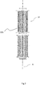
- the self-cleaning filter 1 comprises an entrance opening 2, a delivery opening 3 and a filtrating tubular element 10 configured for filtering the liquid flowing from the entrance opening 2 to the delivery opening 3.
- the filtrating tubular element 10 extends along a longitudinal axis of development "A".
- the filtrating tubular element 10 has a circular cross-section.
- the filtrating tubular element 10 has a filtrating surface, in the example identified by the inner surface 10a, and an opposite external surface 10b. According to a preferred embodiment, the filtrating tubular element 10 is identified by a filtrating net. In an alternative embodiment, illustrated for example in figure 2 , the filtrating tubular element 10 is identified by a pleated filtrating layer, e.g. it has a plurality of pleats arranged parallelly to the longitudinal axis development.
- the self-cleaning filter 1 comprises one or more cleaning elements 4 arranged radially so as to rotate relative to the filtrating tubular element 10 and spaced between them along the longitudinal direction of development "A". Specifically, the cleaning elements 4 are arranged such as to rotate about a rotation axis extended along the longitudinal direction of development "A".
- the cleaning elements 4 are arranged angularly spaced between them. Specifically, two cleaning elements 4 arranged adjacent along the longitudinal direction of development "A" are angularly spaced of 120°.
- the filter 1 comprises a shaft 8 arranged centrally and oriented along the longitudinal direction of development "A".
- Cleaning elements 4 are connected to the shaft 8 which, rotating, makes them rotate with respect to the filtrating tubular element 10.
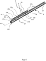
- each cleaning element travels across the inner surface 10a advancing along an advancement direction "B", as shown for example in figures 3 , 5 , 6 and 7 .
- each cleaning element 4 comprises at least a first suction inlet 5 substantially developing along the longitudinal direction of development 10, in particular located near the inner surface 10a thereof.
- the first suction inlet 5 has the function of sucking impurities filtered by the inner surface 10a of the filtrating tubular element 10.
- the first suction inlet 5 comprises a slot 15 preferably of constant width, extending along the longitudinal direction of development "A" for more than 90% of the length of the cleaning element 4.
- each cleaning element 4 comprises a front edge 21a and a back edge 21b with respect to the advancement direction "B", which at least two profiles are connected to, respectively a front profile 22a and a back profile 22b.
- Profiles 22a, 22b are put in contact with the inner surface 10a and are configured to keep such contact during the advancement of the cleaning element 4 in the cleaning operation. Specifically, such contact is elastically maintained.
- profiles 22a, 22b can be made of flexible polymeric material, which is particularly suitable to slide on the inner surface 10a minimizing friction and the potential mechanical removal of dirt.
- Such profiles enclose a cleaning area 23 comprised between the suction inlet 5 and the portion of inner surface 10a onto which the inlet 5 itself faces.
- Profiles 22a, 22b, being in contact with the inner surface 10a, enclose peripherally the suction inlet 5. Thereby the dirt removed is isolated within the cleaning area 23 such that it is sucked without being spread in the fluid to be treated.
- Each cleaning element 4 in addition to the front edge 21a and the back edge 21b, has a pair of side edges 21c and comprises a pair of side edges 22c, each connected to a respective side edge 21c.
- profiles 22a, 22b, 22c are connected between them such as to define a closed wall. Such closed wall, put in contact with the inner surface 10a, isolates completely the cleaning area 23 with respect to the fluid to be filtered, making sure that the sucked fluid takes part in the removal of the deposited residues.
- cleaning elements 4 are preferably spaced along a longitudinal direction of development "A" such that, after their rotation around the longitudinal direction of development "A” of the filtrating tubular element 10, surfaces swept by the first suction inlets 5 of two adjacent cleaning elements 4 overlap with a ratio of overlapping area and overall area of the first suction inlet 5 comprised in a range between 5% and 35%.
- each cleaning element 4 comprises in particular a pair of rods 6 and a pad 7.
- Each rod 6 is radially oriented with respect to the filtrating tubular element 10.
- each rod 6 has one first end 6a and one second end 6b. The first end 6a is connected to the aforementioned shaft 8.
- the pad 7 is connected to the second ends 6b of the rods 6, and it is in particular arranged transversally with respect to them. Such pad 6 is arranged in an area near to the inner surface 10a of the filtrating tubular element 10.
- each cleaning element 4 has rapid connecting means 19 active between the rod 6 and the pad 7.
- Such rapid connecting means 19 have the function to connect/disconnect the rod 6 from the pad 7 and, for example, can comprise one or more teeth 20 which snap-connect within the pad 7.
- rapid connecting means 19 ensure a firm fixing of the pad 7 on the rod 6, which is particularly useful when the cleaning element 4 is extracted by the filtrating tubular element 10 to carry out maintenance operations.
- the pad 7 substantially extends parallelly with respect to the longitudinal direction of development "A".
- the first above described suction inlet 5 is obtained on the pad 7.
- Each cleaning element 4 can advantageously comprise at least an elastic element, in particular an elastic bellow, connected to the pad 7 and configured for pushing it against the inner surface 10a.
- the pad 7 can be made of plastic and/or metal and/or elastomeric material.
- the front 21a, back 21b and side edges 21c of the cleaning element 4 are defined on the pad 7.
- the profiles 22a, 22b are thus connected to the pad 7.
- Side profiles 22c are also connected to the pad 7.
- the profiles 22a, 22b and side profiles 22c are defined by the walls of the pad 7 thereof, in this case made of an elastomeric material.
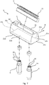
- each cleaning element 4 comprises contact cleaning means 9, arranged in particular on the pad 7.
- contact cleaning means 9 are configured for rubbing on the inner surface 10a of the filtrating tubular element 10, such as to remove dirt.
- contact cleaning means 9 are placed in front of the first suction inlet 5 along the advancement direction "B".
- contact cleaning means 9 can be placed behind the first suction inlet 5 along the direction of advancement "B".
- contact cleaning means 9 comprise a plurality of brushes 11.
- Each brush 11 is fixed to a respective cleaning element 4, and it is configured for sliding in contact with the inner surface 10a of the filtrating tubular element 10 along the mentioned direction of advancement "B".
- the brush 11 allows to remove by mechanical action a greater amount of dirt.
- each cleaning element 4 can have a seat 12, in particular obtained on the pad 7.
- the mentioned brush 11 is arranged inside the seat 12.
- each brush 11 can be inserted/removed in the seat 12, such as to be connected/disconnected to the respective cleaning element 4.
- a pair of plugs fix the brush 11 inside the seat 12. Such plugs are themselves a fixing mechanism known to the person skilled in the art and will not be thus further described.
- removability of the brushes 11 allows to replace them when they are worn or, alternatively, to select a particular type of brush 11 which is more suitable for the specific type of filtrating tubular element 10 assembled on the filter 1.
- the cleaning element 4 can have a second suction inlet 13, distinct with respect to the first suction inlet 5.
- the second suction inlet 13 is arranged at the seat 12.
- the second suction inlet 13 is oriented such that it faces the brush 11.
- the second suction inlet 13 is defined by a plurality of holes 14. Such holes are aligned along a transverse direction, and in particular, the direction of advancement "B" of the cleaning element 4. Specifically, the second suction inlet 13 is placed between the first suction inlet 5 and the brush 11.
- this arrangement of the second suction inlet 13, in particular in combination with the closed wall in contact with the inner surface 10a allows to suck dirt immediately after the mechanical action of the brush 11 has separated it from the filtrating tubular element 10, preventing it from depositing again.
- the fluid dynamic action of the second suction inlet 13 occurs at the same time as the mechanical action of the brush 11.
- the second suction inlet 13 faces the inner surface 10a.
- the shape and size of the second suction inlet 13 are preferably equal to those of the first suction inlet 5.
- the above mentioned brush 11 is enclosed between the front 22a and back profiles 22b, in particular, placed between the first 5 and the second suction inlet 13.
- dirt removed by the mechanical action of the brush 11 is substantially enclosed inside the cleaning area 23 and sucked at the same time by the first 5 and second suction inlet 13.
- the self-cleaning filter 1 further comprises a suction duct 16 arranged internally to the filtrating tubular element 10, in particular inside the above mentioned shaft 8.
- the suction duct 16 is arranged coaxially with respect to the filtrating tubular element 10.
- the suction duct 16 has a plurality of connecting openings 17, in particular obtained on an external surface of the shaft 8.
- each connecting opening 17 is connected to a respective cleaning element 4 by means of a respective connecting duct 18.
- the connecting duct 18 is thus defined within at least one of two rods 6 forming the cleaning element 4, preferably inside both rods 6.
- each cleaning element 4 is connected directly to a respective connecting opening 17, without using the two rods 6.
- Each connecting opening 17 has a front edge 23a, a back edge 23b and a pair of side edges 23c respectively defining the front edge 21a, the back edge 21b and the pair of side edges 21c of each cleaning element 4.
- the cleaning element 4 comprises neither the above mentioned pad nor the rods, the first suction inlet 5 is directly defined by the connecting opening 17, which therefore results to be part of the cleaning element 4.
- profiles 22a, 22b, 22c protrude radially with respect to the suction duct 16. Profiles 22a, 22b, 22c further delimit peripherally the first suction inlet 5.
Landscapes
- Chemical & Material Sciences (AREA)
- Chemical Kinetics & Catalysis (AREA)
- Cleaning In General (AREA)
Claims (5)
- Selbstreinigender Filter (1), umfassend:- ein filtrierenden rohrförmiges Filterelement (10), das eine Innenfläche (10a) und eine Längserstreckungsrichtung (A) aufweist;- eine Vielzahl von Reinigungselementen (4), die in das filtrierende rohrförmige Element (10) eingesetzt und so konfiguriert sind, dass sie sich um die Längsrichtung der Längerstreckung (A) drehen, wobei sich jedes entlang einer jeweiligen Vorwärtsbewegungsrichtung (B) bewegt, wobei die Reinigungselemente (4) entlang der Längserstreckung (A) voneinander beabstandet sind, wobei jedes Reinigungselement (4) eine Vorderkante (21a), eine Hinterkante (21b) und ein Paar Seitenkanten (21c) aufweist, wobei jedes Reinigungselement (4) mindestens einen ersten Saugeinlass (5) umfasst, der der Innenfläche (10a) zugewandt und in der Nähe der Innenfläche (10a) angeordnet ist;wobei jedes Reinigungselement (4) ein vorderes Profil (22a) hat, das mit der vorderen Kante (21a) verbunden ist, und ein hinteres Profil (22b), das mit der hinteren Kante (21b) verbunden ist, wobei die Profile (22a, 22b) in Kontakt mit der inneren Oberfläche (10a) des filtrierenden rohrförmigen Körpers 15 (10) gebracht werden und so konfiguriert sind, dass sie während der Vorwärtsbewegung entlang der inneren Oberfläche (10b) in Kontakt bleiben, um einen Reinigungsbereich (23) zwischen dem Saugeinlass (5) und der inneren Oberfläche (10a) zu isolieren, ein Paar von Seitenprofilen (22c), die jeweils mit einer entsprechenden Seitenkante (21c) verbunden sind, wobei die Profile (22a, 22b, 22c) so miteinander verbunden sind, dass sie eine geschlossene und flexible Wand bilden;
dadurch gekennzeichnet, dass der selbstreinigende Filter (1) Kontaktreinigungsmittel (9) umfasst, die so konfiguriert sind, dass sie auf die Innenfläche (10a) aufschlägen, um Schmutz von der Innenfläche (10a) zu entfernen, wobei die Kontaktreinigungsmittel (9) eine Vielzahl von Bürsten (11) umfassen, die jeweils an einem entsprechenden Reinigungselement (4) befestigt und so konfiguriert sind, dass sie in Kontakt mit der Innenfläche (10a) des filtrierenden rohrförmigen Elements (10) entlang der Richtung der Vorwärtsbewegung (B) gleiten. - Selbstreinigender Filter (1) nach dem vorhergehenden Anspruch, dadurch gekennzeichnet, dass jedes Reinigungselement (4) einen Sitz (12) aufweist, wobei jede Bürste (11) in einen jeweiligen Sitz (12) einführbar/entfernbar ist, um mit dem jeweiligen Reinigungselement (4) verbunden/von ihm entfernt zu werden.
- Selbstreinigender Filter (1) nach dem vorhergehenden Anspruch, dadurch gekennzeichnet, dass jedes Reinigungselement (4) einen zweiten Saugeinlass (13) umfasst, der in der Nähe des Sitzes (12) angeordnet ist.
- Selbstreinigender Filter (1) nach dem vorhergehenden Anspruch, dadurch gekennzeichnet, dass der zweite Saugeinlass (13) der Innenfläche (10a) zugewandt ist und die Bürste (11) zwischen dem ersten Saugeinlass (5) und dem zweiten Saugeinlass (13) angeordnet ist.
- Selbstreinigender Filter (1) nach Anspruch 3, dadurch gekennzeichnet, dass der zweite Saugeinlass (13) der Bürste (11) zugewandt ist und zwischen dem ersten Saugeinlass (5) und der Bürste (11) angeordnet ist
Applications Claiming Priority (1)
| Application Number | Priority Date | Filing Date | Title |
|---|---|---|---|
| IT102018000003030A IT201800003030A1 (it) | 2018-02-26 | 2018-02-26 | Filtro autopulente |
Publications (2)
| Publication Number | Publication Date |
|---|---|
| EP3530336A1 EP3530336A1 (de) | 2019-08-28 |
| EP3530336B1 true EP3530336B1 (de) | 2021-08-04 |
Family
ID=62218263
Family Applications (1)
| Application Number | Title | Priority Date | Filing Date |
|---|---|---|---|
| EP19159110.6A Active EP3530336B1 (de) | 2018-02-26 | 2019-02-25 | Selbstreinigender filter |
Country Status (2)
| Country | Link |
|---|---|
| EP (1) | EP3530336B1 (de) |
| IT (1) | IT201800003030A1 (de) |
Families Citing this family (4)
| Publication number | Priority date | Publication date | Assignee | Title |
|---|---|---|---|---|
| IT202100012296A1 (it) * | 2021-05-13 | 2022-11-13 | Elfi S R L | Filtro per ritenere, o trattenere, corrispondenti residui o particelle solide che sono contenute in un corrispondente fluido da filtrare |
| PL439708A1 (pl) * | 2021-12-01 | 2023-06-05 | Pftechnology Spółka Z Ograniczoną Odpowiedzialnością Spółka Komandytowa | Dysza czyszcząca do sita filtracyjnego szczelinowego, o selektywności poniżej 90 μm |
| IT202300005982A1 (it) * | 2023-03-29 | 2024-09-29 | Asco Filtri S P A | Filtro autopulente |
| WO2026003836A1 (en) * | 2024-06-27 | 2026-01-02 | Odis Irrigation Equipment (2002) Ltd. | Filter cleaning hybrid device |
Family Cites Families (8)
| Publication number | Priority date | Publication date | Assignee | Title |
|---|---|---|---|---|
| DE29809202U1 (de) * | 1998-05-22 | 1998-07-30 | Boll & Kirch Filterbau GmbH, 50170 Kerpen | Rückspülfilter |
| US20090050582A1 (en) | 2007-08-23 | 2009-02-26 | Shmuel Gil | Self-Cleaning System For Filter |
| US20140021125A1 (en) | 2012-07-18 | 2014-01-23 | Dan Lin | Self-cleaning suction filter |
| EP2767321B1 (de) | 2013-02-13 | 2018-06-27 | F.M., S.r.L. Unipersonale | Selbstreinigender Filter |
| DE202013105966U1 (de) * | 2013-12-30 | 2014-03-06 | Wuxi Huahong Information Technology Co., Ltd. | Selbstreinigendes Filter |
| ES2662057T3 (es) * | 2014-09-19 | 2018-04-05 | Sati S.R.L. | Filtro de autolimpieza |
| CN105214361B (zh) * | 2015-10-28 | 2017-11-21 | 安阳市昌明环保设备有限责任公司 | 旋转冲洗过滤器 |
| CN105833590A (zh) * | 2016-06-09 | 2016-08-10 | 威海中远造船科技有限公司 | 负压式自清洗过滤器 |
-
2018
- 2018-02-26 IT IT102018000003030A patent/IT201800003030A1/it unknown
-
2019
- 2019-02-25 EP EP19159110.6A patent/EP3530336B1/de active Active
Non-Patent Citations (1)
| Title |
|---|
| None * |
Also Published As
| Publication number | Publication date |
|---|---|
| IT201800003030A1 (it) | 2019-08-26 |
| EP3530336A1 (de) | 2019-08-28 |
Similar Documents
| Publication | Publication Date | Title |
|---|---|---|
| EP3530336B1 (de) | Selbstreinigender filter | |
| CN112892044B (zh) | 过滤单元 | |
| ES2542646T3 (es) | Filtro de flujo reversible con dispositivo de barrido | |
| JP6158581B2 (ja) | 濾過装置 | |
| US20150165354A1 (en) | Spiral Irrigation Filter Cleaning Apparatus | |
| CN111790198B (zh) | 清洁尤其导水家用器具膜片元件的系统、刮拭元件及方法 | |
| EP1361914A1 (de) | Selbstreinigungstrommelfilter | |
| US20150265952A1 (en) | Self-Cleaning Intake Screen | |
| CN102089055A (zh) | 水滤网带模块 | |
| EP3424578B1 (de) | Selbstreinigender filter | |
| DE59405787D1 (de) | Rückspülbares Filter für Flüssigkeiten | |
| WO2018231338A1 (en) | Filter device and method | |
| EP2341998B1 (de) | Verfahren und vorrichtung zur reinigung eines filters für flüssigkeiten | |
| ES2756710T3 (es) | Máquina de limpieza subacuática con una instalación de filtro | |
| JPS5811367Y2 (ja) | ストレ−ナにおける逆洗装置 | |
| JPS5932917A (ja) | 内部収集濾過用バツグの効率増進方法とその装置 | |
| TWM506644U (zh) | 自動雜質捕捉器 | |
| JPH0717306U (ja) | ドラム型クーラント液ろ過装置 | |
| EP3816337A1 (de) | Trockner mit einem selbstreinigenden filter | |
| JP3668217B2 (ja) | フィルター装置 | |
| US2232618A (en) | Fluid filtering or straining element | |
| US20170165596A1 (en) | Bag filter assembly | |
| WO2026003836A1 (en) | Filter cleaning hybrid device | |
| CN117259006A (zh) | 一种磁性过滤箱体 | |
| FI98050C (fi) | Suodatinlaite |
Legal Events
| Date | Code | Title | Description |
|---|---|---|---|
| PUAI | Public reference made under article 153(3) epc to a published international application that has entered the european phase |
Free format text: ORIGINAL CODE: 0009012 |
|
| STAA | Information on the status of an ep patent application or granted ep patent |
Free format text: STATUS: THE APPLICATION HAS BEEN PUBLISHED |
|
| AK | Designated contracting states |
Kind code of ref document: A1 Designated state(s): AL AT BE BG CH CY CZ DE DK EE ES FI FR GB GR HR HU IE IS IT LI LT LU LV MC MK MT NL NO PL PT RO RS SE SI SK SM TR |
|
| AX | Request for extension of the european patent |
Extension state: BA ME |
|
| STAA | Information on the status of an ep patent application or granted ep patent |
Free format text: STATUS: REQUEST FOR EXAMINATION WAS MADE |
|
| 17P | Request for examination filed |
Effective date: 20200226 |
|
| RBV | Designated contracting states (corrected) |
Designated state(s): AL AT BE BG CH CY CZ DE DK EE ES FI FR GB GR HR HU IE IS IT LI LT LU LV MC MK MT NL NO PL PT RO RS SE SI SK SM TR |
|
| STAA | Information on the status of an ep patent application or granted ep patent |
Free format text: STATUS: EXAMINATION IS IN PROGRESS |
|
| 17Q | First examination report despatched |
Effective date: 20200723 |
|
| GRAP | Despatch of communication of intention to grant a patent |
Free format text: ORIGINAL CODE: EPIDOSNIGR1 |
|
| STAA | Information on the status of an ep patent application or granted ep patent |
Free format text: STATUS: GRANT OF PATENT IS INTENDED |
|
| INTG | Intention to grant announced |
Effective date: 20210226 |
|
| GRAS | Grant fee paid |
Free format text: ORIGINAL CODE: EPIDOSNIGR3 |
|
| GRAA | (expected) grant |
Free format text: ORIGINAL CODE: 0009210 |
|
| STAA | Information on the status of an ep patent application or granted ep patent |
Free format text: STATUS: THE PATENT HAS BEEN GRANTED |
|
| AK | Designated contracting states |
Kind code of ref document: B1 Designated state(s): AL AT BE BG CH CY CZ DE DK EE ES FI FR GB GR HR HU IE IS IT LI LT LU LV MC MK MT NL NO PL PT RO RS SE SI SK SM TR |
|
| REG | Reference to a national code |
Ref country code: GB Ref legal event code: FG4D |
|
| REG | Reference to a national code |
Ref country code: AT Ref legal event code: REF Ref document number: 1416378 Country of ref document: AT Kind code of ref document: T Effective date: 20210815 |
|
| REG | Reference to a national code |
Ref country code: CH Ref legal event code: EP |
|
| REG | Reference to a national code |
Ref country code: DE Ref legal event code: R096 Ref document number: 602019006498 Country of ref document: DE |
|
| REG | Reference to a national code |
Ref country code: IE Ref legal event code: FG4D |
|
| REG | Reference to a national code |
Ref country code: LT Ref legal event code: MG9D |
|
| REG | Reference to a national code |
Ref country code: NL Ref legal event code: MP Effective date: 20210804 |
|
| REG | Reference to a national code |
Ref country code: AT Ref legal event code: MK05 Ref document number: 1416378 Country of ref document: AT Kind code of ref document: T Effective date: 20210804 |
|
| PG25 | Lapsed in a contracting state [announced via postgrant information from national office to epo] |
Ref country code: SE Free format text: LAPSE BECAUSE OF FAILURE TO SUBMIT A TRANSLATION OF THE DESCRIPTION OR TO PAY THE FEE WITHIN THE PRESCRIBED TIME-LIMIT Effective date: 20210804 Ref country code: RS Free format text: LAPSE BECAUSE OF FAILURE TO SUBMIT A TRANSLATION OF THE DESCRIPTION OR TO PAY THE FEE WITHIN THE PRESCRIBED TIME-LIMIT Effective date: 20210804 Ref country code: FI Free format text: LAPSE BECAUSE OF FAILURE TO SUBMIT A TRANSLATION OF THE DESCRIPTION OR TO PAY THE FEE WITHIN THE PRESCRIBED TIME-LIMIT Effective date: 20210804 Ref country code: ES Free format text: LAPSE BECAUSE OF FAILURE TO SUBMIT A TRANSLATION OF THE DESCRIPTION OR TO PAY THE FEE WITHIN THE PRESCRIBED TIME-LIMIT Effective date: 20210804 Ref country code: PT Free format text: LAPSE BECAUSE OF FAILURE TO SUBMIT A TRANSLATION OF THE DESCRIPTION OR TO PAY THE FEE WITHIN THE PRESCRIBED TIME-LIMIT Effective date: 20211206 Ref country code: NO Free format text: LAPSE BECAUSE OF FAILURE TO SUBMIT A TRANSLATION OF THE DESCRIPTION OR TO PAY THE FEE WITHIN THE PRESCRIBED TIME-LIMIT Effective date: 20211104 Ref country code: HR Free format text: LAPSE BECAUSE OF FAILURE TO SUBMIT A TRANSLATION OF THE DESCRIPTION OR TO PAY THE FEE WITHIN THE PRESCRIBED TIME-LIMIT Effective date: 20210804 Ref country code: AT Free format text: LAPSE BECAUSE OF FAILURE TO SUBMIT A TRANSLATION OF THE DESCRIPTION OR TO PAY THE FEE WITHIN THE PRESCRIBED TIME-LIMIT Effective date: 20210804 Ref country code: BG Free format text: LAPSE BECAUSE OF FAILURE TO SUBMIT A TRANSLATION OF THE DESCRIPTION OR TO PAY THE FEE WITHIN THE PRESCRIBED TIME-LIMIT Effective date: 20211104 Ref country code: LT Free format text: LAPSE BECAUSE OF FAILURE TO SUBMIT A TRANSLATION OF THE DESCRIPTION OR TO PAY THE FEE WITHIN THE PRESCRIBED TIME-LIMIT Effective date: 20210804 |
|
| PG25 | Lapsed in a contracting state [announced via postgrant information from national office to epo] |
Ref country code: PL Free format text: LAPSE BECAUSE OF FAILURE TO SUBMIT A TRANSLATION OF THE DESCRIPTION OR TO PAY THE FEE WITHIN THE PRESCRIBED TIME-LIMIT Effective date: 20210804 Ref country code: LV Free format text: LAPSE BECAUSE OF FAILURE TO SUBMIT A TRANSLATION OF THE DESCRIPTION OR TO PAY THE FEE WITHIN THE PRESCRIBED TIME-LIMIT Effective date: 20210804 Ref country code: GR Free format text: LAPSE BECAUSE OF FAILURE TO SUBMIT A TRANSLATION OF THE DESCRIPTION OR TO PAY THE FEE WITHIN THE PRESCRIBED TIME-LIMIT Effective date: 20211105 |
|
| PG25 | Lapsed in a contracting state [announced via postgrant information from national office to epo] |
Ref country code: NL Free format text: LAPSE BECAUSE OF FAILURE TO SUBMIT A TRANSLATION OF THE DESCRIPTION OR TO PAY THE FEE WITHIN THE PRESCRIBED TIME-LIMIT Effective date: 20210804 |
|
| PG25 | Lapsed in a contracting state [announced via postgrant information from national office to epo] |
Ref country code: DK Free format text: LAPSE BECAUSE OF FAILURE TO SUBMIT A TRANSLATION OF THE DESCRIPTION OR TO PAY THE FEE WITHIN THE PRESCRIBED TIME-LIMIT Effective date: 20210804 |
|
| REG | Reference to a national code |
Ref country code: DE Ref legal event code: R097 Ref document number: 602019006498 Country of ref document: DE |
|
| PG25 | Lapsed in a contracting state [announced via postgrant information from national office to epo] |
Ref country code: SM Free format text: LAPSE BECAUSE OF FAILURE TO SUBMIT A TRANSLATION OF THE DESCRIPTION OR TO PAY THE FEE WITHIN THE PRESCRIBED TIME-LIMIT Effective date: 20210804 Ref country code: SK Free format text: LAPSE BECAUSE OF FAILURE TO SUBMIT A TRANSLATION OF THE DESCRIPTION OR TO PAY THE FEE WITHIN THE PRESCRIBED TIME-LIMIT Effective date: 20210804 Ref country code: RO Free format text: LAPSE BECAUSE OF FAILURE TO SUBMIT A TRANSLATION OF THE DESCRIPTION OR TO PAY THE FEE WITHIN THE PRESCRIBED TIME-LIMIT Effective date: 20210804 Ref country code: EE Free format text: LAPSE BECAUSE OF FAILURE TO SUBMIT A TRANSLATION OF THE DESCRIPTION OR TO PAY THE FEE WITHIN THE PRESCRIBED TIME-LIMIT Effective date: 20210804 Ref country code: CZ Free format text: LAPSE BECAUSE OF FAILURE TO SUBMIT A TRANSLATION OF THE DESCRIPTION OR TO PAY THE FEE WITHIN THE PRESCRIBED TIME-LIMIT Effective date: 20210804 Ref country code: AL Free format text: LAPSE BECAUSE OF FAILURE TO SUBMIT A TRANSLATION OF THE DESCRIPTION OR TO PAY THE FEE WITHIN THE PRESCRIBED TIME-LIMIT Effective date: 20210804 |
|
| PLBE | No opposition filed within time limit |
Free format text: ORIGINAL CODE: 0009261 |
|
| STAA | Information on the status of an ep patent application or granted ep patent |
Free format text: STATUS: NO OPPOSITION FILED WITHIN TIME LIMIT |
|
| 26N | No opposition filed |
Effective date: 20220506 |
|
| PG25 | Lapsed in a contracting state [announced via postgrant information from national office to epo] |
Ref country code: SI Free format text: LAPSE BECAUSE OF FAILURE TO SUBMIT A TRANSLATION OF THE DESCRIPTION OR TO PAY THE FEE WITHIN THE PRESCRIBED TIME-LIMIT Effective date: 20210804 |
|
| PG25 | Lapsed in a contracting state [announced via postgrant information from national office to epo] |
Ref country code: MC Free format text: LAPSE BECAUSE OF FAILURE TO SUBMIT A TRANSLATION OF THE DESCRIPTION OR TO PAY THE FEE WITHIN THE PRESCRIBED TIME-LIMIT Effective date: 20210804 |
|
| REG | Reference to a national code |
Ref country code: CH Ref legal event code: PL |
|
| REG | Reference to a national code |
Ref country code: BE Ref legal event code: MM Effective date: 20220228 |
|
| PG25 | Lapsed in a contracting state [announced via postgrant information from national office to epo] |
Ref country code: LU Free format text: LAPSE BECAUSE OF NON-PAYMENT OF DUE FEES Effective date: 20220225 |
|
| PG25 | Lapsed in a contracting state [announced via postgrant information from national office to epo] |
Ref country code: FR Free format text: LAPSE BECAUSE OF NON-PAYMENT OF DUE FEES Effective date: 20220228 |
|
| PG25 | Lapsed in a contracting state [announced via postgrant information from national office to epo] |
Ref country code: LI Free format text: LAPSE BECAUSE OF NON-PAYMENT OF DUE FEES Effective date: 20220228 Ref country code: IE Free format text: LAPSE BECAUSE OF NON-PAYMENT OF DUE FEES Effective date: 20220225 Ref country code: CH Free format text: LAPSE BECAUSE OF NON-PAYMENT OF DUE FEES Effective date: 20220228 |
|
| PG25 | Lapsed in a contracting state [announced via postgrant information from national office to epo] |
Ref country code: BE Free format text: LAPSE BECAUSE OF NON-PAYMENT OF DUE FEES Effective date: 20220228 |
|
| P01 | Opt-out of the competence of the unified patent court (upc) registered |
Effective date: 20230602 |
|
| P02 | Opt-out of the competence of the unified patent court (upc) changed |
Effective date: 20230821 |
|
| GBPC | Gb: european patent ceased through non-payment of renewal fee |
Effective date: 20230225 |
|
| PG25 | Lapsed in a contracting state [announced via postgrant information from national office to epo] |
Ref country code: GB Free format text: LAPSE BECAUSE OF NON-PAYMENT OF DUE FEES Effective date: 20230225 |
|
| PG25 | Lapsed in a contracting state [announced via postgrant information from national office to epo] |
Ref country code: GB Free format text: LAPSE BECAUSE OF NON-PAYMENT OF DUE FEES Effective date: 20230225 |
|
| PG25 | Lapsed in a contracting state [announced via postgrant information from national office to epo] |
Ref country code: MK Free format text: LAPSE BECAUSE OF FAILURE TO SUBMIT A TRANSLATION OF THE DESCRIPTION OR TO PAY THE FEE WITHIN THE PRESCRIBED TIME-LIMIT Effective date: 20210804 Ref country code: CY Free format text: LAPSE BECAUSE OF FAILURE TO SUBMIT A TRANSLATION OF THE DESCRIPTION OR TO PAY THE FEE WITHIN THE PRESCRIBED TIME-LIMIT Effective date: 20210804 |
|
| PG25 | Lapsed in a contracting state [announced via postgrant information from national office to epo] |
Ref country code: HU Free format text: LAPSE BECAUSE OF FAILURE TO SUBMIT A TRANSLATION OF THE DESCRIPTION OR TO PAY THE FEE WITHIN THE PRESCRIBED TIME-LIMIT; INVALID AB INITIO Effective date: 20190225 |
|
| PG25 | Lapsed in a contracting state [announced via postgrant information from national office to epo] |
Ref country code: MT Free format text: LAPSE BECAUSE OF FAILURE TO SUBMIT A TRANSLATION OF THE DESCRIPTION OR TO PAY THE FEE WITHIN THE PRESCRIBED TIME-LIMIT Effective date: 20210804 |
|
| PGFP | Annual fee paid to national office [announced via postgrant information from national office to epo] |
Ref country code: DE Payment date: 20250218 Year of fee payment: 7 |
|
| PG25 | Lapsed in a contracting state [announced via postgrant information from national office to epo] |
Ref country code: TR Free format text: LAPSE BECAUSE OF FAILURE TO SUBMIT A TRANSLATION OF THE DESCRIPTION OR TO PAY THE FEE WITHIN THE PRESCRIBED TIME-LIMIT Effective date: 20210804 |
|
| PGFP | Annual fee paid to national office [announced via postgrant information from national office to epo] |
Ref country code: IT Payment date: 20260223 Year of fee payment: 8 |