EP3530146A1 - Profile für den bau tragender strukturen und entsprechendes kupplungs- und verbindungssystem - Google Patents
Profile für den bau tragender strukturen und entsprechendes kupplungs- und verbindungssystem Download PDFInfo
- Publication number
- EP3530146A1 EP3530146A1 EP19000093.5A EP19000093A EP3530146A1 EP 3530146 A1 EP3530146 A1 EP 3530146A1 EP 19000093 A EP19000093 A EP 19000093A EP 3530146 A1 EP3530146 A1 EP 3530146A1
- Authority
- EP
- European Patent Office
- Prior art keywords
- legs
- post
- elements
- profiles
- section
- Prior art date
- Legal status (The legal status is an assumption and is not a legal conclusion. Google has not performed a legal analysis and makes no representation as to the accuracy of the status listed.)
- Granted
Links
- 230000008878 coupling Effects 0.000 title claims description 7
- 238000010168 coupling process Methods 0.000 title claims description 7
- 238000005859 coupling reaction Methods 0.000 title claims description 7
- 229910052751 metal Inorganic materials 0.000 claims description 9
- 239000000725 suspension Substances 0.000 claims description 5
- 238000006073 displacement reaction Methods 0.000 claims description 4
- 230000035515 penetration Effects 0.000 claims description 2
- 239000002356 single layer Substances 0.000 claims description 2
- 230000001154 acute effect Effects 0.000 claims 1
- 239000002184 metal Substances 0.000 description 8
- 239000002131 composite material Substances 0.000 description 5
- 238000001125 extrusion Methods 0.000 description 5
- 238000004519 manufacturing process Methods 0.000 description 4
- 230000015572 biosynthetic process Effects 0.000 description 2
- 238000004140 cleaning Methods 0.000 description 2
- 230000008602 contraction Effects 0.000 description 2
- 230000003670 easy-to-clean Effects 0.000 description 2
- 238000005755 formation reaction Methods 0.000 description 2
- 239000000463 material Substances 0.000 description 2
- 230000007246 mechanism Effects 0.000 description 2
- 150000001875 compounds Chemical class 0.000 description 1
- 238000010276 construction Methods 0.000 description 1
- 230000008021 deposition Effects 0.000 description 1
- 239000000428 dust Substances 0.000 description 1
- 230000000694 effects Effects 0.000 description 1
- 238000003780 insertion Methods 0.000 description 1
- 230000037431 insertion Effects 0.000 description 1
- 239000010410 layer Substances 0.000 description 1
- 239000007788 liquid Substances 0.000 description 1
Images


Classifications
-
- F—MECHANICAL ENGINEERING; LIGHTING; HEATING; WEAPONS; BLASTING
- F16—ENGINEERING ELEMENTS AND UNITS; GENERAL MEASURES FOR PRODUCING AND MAINTAINING EFFECTIVE FUNCTIONING OF MACHINES OR INSTALLATIONS; THERMAL INSULATION IN GENERAL
- F16B—DEVICES FOR FASTENING OR SECURING CONSTRUCTIONAL ELEMENTS OR MACHINE PARTS TOGETHER, e.g. NAILS, BOLTS, CIRCLIPS, CLAMPS, CLIPS OR WEDGES; JOINTS OR JOINTING
- F16B12/00—Jointing of furniture or the like, e.g. hidden from exterior
- F16B12/10—Jointing of furniture or the like, e.g. hidden from exterior using pegs, bolts, tenons, clamps, clips, or the like
- F16B12/28—Jointing of furniture or the like, e.g. hidden from exterior using pegs, bolts, tenons, clamps, clips, or the like for metal furniture parts
- F16B12/38—Jointing of furniture or the like, e.g. hidden from exterior using pegs, bolts, tenons, clamps, clips, or the like for metal furniture parts using snap-action elements
-
- A—HUMAN NECESSITIES
- A47—FURNITURE; DOMESTIC ARTICLES OR APPLIANCES; COFFEE MILLS; SPICE MILLS; SUCTION CLEANERS IN GENERAL
- A47B—TABLES; DESKS; OFFICE FURNITURE; CABINETS; DRAWERS; GENERAL DETAILS OF FURNITURE
- A47B57/00—Cabinets, racks or shelf units, characterised by features for adjusting shelves or partitions
- A47B57/30—Cabinets, racks or shelf units, characterised by features for adjusting shelves or partitions with means for adjusting the height of detachable shelf supports
- A47B57/48—Cabinets, racks or shelf units, characterised by features for adjusting shelves or partitions with means for adjusting the height of detachable shelf supports consisting of tongues, pins or similar projecting means coacting with openings
-
- A—HUMAN NECESSITIES
- A47—FURNITURE; DOMESTIC ARTICLES OR APPLIANCES; COFFEE MILLS; SPICE MILLS; SUCTION CLEANERS IN GENERAL
- A47B—TABLES; DESKS; OFFICE FURNITURE; CABINETS; DRAWERS; GENERAL DETAILS OF FURNITURE
- A47B96/00—Details of cabinets, racks or shelf units not covered by a single one of groups A47B43/00 - A47B95/00; General details of furniture
- A47B96/14—Bars, uprights, struts, or like supports, for cabinets, brackets, or the like
- A47B96/1466—Bars, uprights, struts, or like supports, for cabinets, brackets, or the like with longitudinal grooves
- A47B96/1475—Bars, uprights, struts, or like supports, for cabinets, brackets, or the like with longitudinal grooves and perforations
-
- A—HUMAN NECESSITIES
- A47—FURNITURE; DOMESTIC ARTICLES OR APPLIANCES; COFFEE MILLS; SPICE MILLS; SUCTION CLEANERS IN GENERAL
- A47B—TABLES; DESKS; OFFICE FURNITURE; CABINETS; DRAWERS; GENERAL DETAILS OF FURNITURE
- A47B47/00—Cabinets, racks or shelf units, characterised by features related to dismountability or building-up from elements
- A47B47/02—Cabinets, racks or shelf units, characterised by features related to dismountability or building-up from elements made of metal only
Definitions
- the invention relates to profiles and structural elements for the construction of supporting structures, such as e.g. Shelving, support racks, bookshelves, and the coupling and connection system between the individual structural elements for a quick and easy assembly / disassembly, without the use of specific tools to achieve.
- supporting structures such as e.g. Shelving, support racks, bookshelves, and the coupling and connection system between the individual structural elements for a quick and easy assembly / disassembly, without the use of specific tools to achieve.
- a "frame” known which consists of vertical posts and horizontal side rails, or shelves; wherein the posts consist of parallel profiles which between them, in the region of the vertical connecting surfaces, a number of equally spaced suspension elements for the respective depending of the longitudinal beams, or the horizontal, insertable between the composite profiles of the posts shelves have.
- the posts of said structure are complex in their manufacture, are heavy and their cleaning is tedious.
- GB 2048351 A1 is a structure for furniture, such as shelves, boxes or tables known which consist of metallic profiles with eg rectangular cross-section and which are connected at their ends.
- the posts of these structures consist of profiles which have a substantially U-shaped cross-section, wherein the flange projecting parallel from the connecting flange are double and spaced from each other.
- the longitudinal legs of said parallel flanges are bent against the connecting flange and are provided with spaced apart and to the longitudinal extent of the post profile horizontally extending slots.
- the structural elements which can be attached to these posts have final formations which can be inserted between the oblong and inflected flanges of the posts, with projecting lateral projections engaging the slots provided on the posts. This intervention is activated by inserting a wedge element.
- the horizontal structural elements on the post by means, mounted on the Endausformept lever which have a Nockenausformung acting on a cross rung, which is slidably mounted on the Endausformung and upon actuation of the lever in the slots of the post intervenes.
- connection system requires final formations with a complex locking mechanism which is expensive to manufacture and requires the use of movable elements such as wedges or cam-shaped lever mechanisms for the purpose of locking / releasing the individual structural elements on the posts.
- movable elements such as wedges or cam-shaped lever mechanisms for the purpose of locking / releasing the individual structural elements on the posts.
- the object of the invention is to provide metallic support structures for the storage, storage and / or the exhibition of goods which consist essentially of vertical posts, fasteners or self-supporting, attachable to these elements and horizontal side rails and / or shelves of the aforementioned type, which are simple and inexpensive to produce, convenient to install / dismantle and easy to clean, preferably metallic simple and inexpensive to produce profiles and use secure coupling and connection systems which provide the structure with considerable stability.
- the support structures which can be realized with the use of profiles and elements according to the invention comprise substantially vertical posts with tubular cross-section, horizontal connecting elements or cantilevers with preferably inverted T-shaped cross section, horizontal side members with U-shaped cross section or tubular, rectangular cross section and shelves with circumferential bent edges.
- the tubular profile of the posts is inventively characterized in that the two outermost legs of the wall which forms the profile inwardly, are bent in the cross section to extend in a straight line while touching each other or are spaced a little from each other.
- said inwardly projecting legs form a right angle with the corresponding outer wall of the profile, said deflection region extending inwardly along, or near, the vertical centerline of the corresponding wall of the profile. It is not excluded the use of compound posts, so that at several than one side, has legs projecting inwards in the cross-section.
- On both of the said inner legs elongated holes or openings are provided according to the invention substantially on the entire longitudinal extent which are arranged on both legs in a corresponding position and spaced from each other.
- the profile of the connecting elements or of the self-attaching elements preferably has a T-shaped cross-section, which can be made of a simple type, for example by extrusion, or can consist of two elements of substantially identical cross-section which are produced by profiling of sheet metal and are arranged longitudinally to one another. or transverse direction are slidably connected so that by mutual displacement is a, variable in length, element available.
- these T-elements have at both ends or, in the case of cantilevered attachment only at one of the ends, a hooked end which is provided on each of the sides with at least one hooking projection which is suitable for insertion into the two inner legs of the aforementioned tubular, the vertical post forming profile, provided slots or openings penetrate and mount.
- the coupling between the aforesaid connecting element or the cantilever element, which preferably has a T-shaped cross-section with the tubular profile which forms the post, is effected by inserting the vertical hooking end of the T-shaped element, which in this area has no horizontal flanges, between the both vertical inner legs of the tubular profile of the post, these legs being slightly spread apart, the penetration of the hooking projections, which protrude laterally from the left and right sides of said hooking end, into the corresponding oblong holes or openings provided on both inner legs of the post, is reached.
- the definitive hooking is done by pushing down the said hooked end inserted between the two legs, or the corresponding connecting element or the cantilevered element, which is pressed down because of the hooking projections provided angled surfaces, a train of the legs of the post against the intermediate Einattide done, whereby a secure, stable and durable hooking is achieved.
- the surfaces or the shape of the Einhticianvorsprünge, or the slots in which they engage and hang be designed such that, in addition to the mutual contraction of the inner legs of the tubular profile of the post, a force component is formed which is suitable to pull the T-section element with the face of the lateral horizontal flanges against the outer surface of the tubular profile of the post, thereby securing the abutment against the post, the position at 90 ° to the post, and the stability of the connection.
- a vertical to be provided externally projecting rib At the said two vertical ribs of the profile of the post can act a corresponding notch which are frontally provided on the horizontal flanges of the T-shaped profile which is pulled horizontally against the latter by the effect of hanging on the post.
- the shelves which are horizontally fastened to the fasteners or to the cantilevered elements which are horizontally fitted and hung on the vertical tubular uprights may be made of sheet metal and have flanges and / or hook-in notches on the underside;
- the invention does not exclude the use of known shelves made of different materials which with known devices for hanging and / or attaching to the corresponding fasteners or to the cantilevered elements with T-shaped cross-section, from.
- the horizontal side members according to the invention may be profiles with U-shaped, tubular or rectangular in cross-section which by extrusion or are made by profiling of sheet metal; at the ends, these are provided with suspension brackets and / or lower Einh brieflykerben which are arranged at a distance from the ends in order to be attached to the corresponding connecting elements or cantilevered elements, which for example have a T-shaped cross-section.
- the invention does not exclude the use of side members made of different materials, which can be fastened or suspended on the connecting elements or on the self-supporting elements with a T-shaped cross section or on the vertical posts by means of known devices.
- the invention does not exclude the production of the tubular profile of the posts and also that of the connecting elements or the self-supporting elements of plastic, e.g. by extrusion, out.
- the structure of a shelf is according to the invention of vertical posts 1, to which a plurality of horizontal connecting elements or cantilevered elements 2 with inverted T-shaped cross-section, mutually vertically spaced, can be used and fastened, composed. At the said fasteners or cantilevered elements 2 horizontal side members 4 and / or horizontal shelves 3 can be attached.
- the invention proposes that the tubular post 1 two rectilinear, inward in has the cross-section projecting and abutting one another, or to each other by a distance from each other leg 1 a, which dimension substantially corresponds to the strength of the Ein Strukturdes 2i of the horizontal Veitatiselements or the cantilevered element 2.
- Said legs 1a have elongated holes or openings 1c into which projections 2c are inserted and which project on both sides from the hooking end 2i of the horizontal connecting element or cantilevered element 2 with a T-shaped cross section.
- the elongated holes or openings 1c may have a downwardly narrowing shape.
- the hooking projections 2c provided at the hooked end 2i are at least two, one at the right and one at the left side, advantageously more than two for stable hooking and preferably their position with respect to the end face of the hooking end 2i be arranged that this surface is applied to the inner surface of the post 1.
- the elongated holes 1c on the legs 1a of the post 1 and / or the EinhNicolvorsprünge 2c are formed such that, during the Einhnature on the connecting element 2, a force component acts, which tends to pull the Ein devisde 2i inward of the cross section of the post 1 and to pull the two legs 1a against the said intermediate hanging end 2i.
- a vertical outwardly projecting longitudinal rib 1b can be provided corresponding to the region of the angling of the two legs 1a of the post inwardly of the cross section, where these form an angle of approximately 90 ° with the outer wall of the profile.
- a notch 2 g which is provided on the front side on the horizontal flanges 2 b of the connecting element or cantilevered element 2, can cooperate.
- This notch 2g and / or the cross section of the ribs 1b can be formed according to the invention such that by the movement of the element 2 against the post 1, which by the force component during the hooking movement between the element 2 and the post 1 is effected, an approximation between the two ribs 1b and a contraction against the vertical flange of the Ein Strukturdes 2i takes place.
- the connecting element or cantilevered element 2 of T-shaped cross section may be of simpler, e.g. by extrusion produced type or composite type, consisting of two substantially identical elements with T-shaped cross-section, be longitudinally displaceable composite type.
- both elements 2 are made by profiling of sheet metal, the vertical flange is single-layered, one of the horizontal flanges is double-layered bent over, while the second horizontal flange 2a is single-layered.
- the two-layer horizontal flange 2a is formed on one of the elements 2, which form the connecting element or the cantilever element, that a distance corresponding to the sheet thickness is maintained between the legs, the assembly of both elements with T-shaped cross-section by inserting the single-layer flange of one element in the free corresponding space of the other element up to the stop of the two vertical flanges, possible.
- This embodiment makes it possible to provide respective longitudinal elongated holes 2e on both assembled and penetrated by the Löngslöcher 2e bolt 2f with heads at both ends secured elements 2 to thereby achieve a longitudinal displacement between the two assembled elements 2, for the purpose of changing the longitudinal extent.
- the invention does not exclude that the two joined elements 2 are connected by a single bolt passing through in order to form a longitudinally extendable connecting element, so that a pivoting movement between the two joined elements is possible in order, in certain situations, to assemble / Disassembly to facilitate the post.
- shelves 3 made of sheet metal with bent edges can be attached, which have at the ends Einh brieflyflansche 3a, 3b and / or latching notches 3c.
- These Einh brieflyflansche allow direct hooking on the vertical flange 2a of the connecting elements or cantilevered elements 2, or the mutual hooking between two ends of two shelves 3.
- the latching notches 3c allow direct engagement with the vertical flanges 2a of the elements 2, which are provided with corresponding notches 2d can be provided. It is also possible to use elements with double-sided hooking possibility 5, which are attached to the elements 2 with hooking flanges 5a arranged on both sides, for the purpose of accommodating the hooking flanges 3a of the shelves 3.
- longitudinal members 4 may be attached to the connecting elements or cantilevered elements 2 with e.g. U-shaped or rectangular tubular cross section are attached. These side rails may be provided at their ends with hooking and / or latching notches similar to those on the shelves.
- the side members 4 may alternatively be provided with Einhticianzitch which are identical to the Einhticiangendes 2i of the connecting elements or cantilevered elements 2, but rotated by 90 ° to the longitudinal extent of the longitudinal members 4 are arranged to be used on the post 1 between the flanges 1a.
- known sensors 6 can be mounted between the connecting elements 2 and the shelves attached to be able to indicate changes in weight on the shelves can.
Landscapes
- Engineering & Computer Science (AREA)
- General Engineering & Computer Science (AREA)
- Mechanical Engineering (AREA)
- Assembled Shelves (AREA)
- Joining Of Building Structures In Genera (AREA)
- Rod-Shaped Construction Members (AREA)
Abstract
Description
- Die Erfindung bezieht sich auf Profile und Strukturelemente für den Bau tragender Strukturen, wie z.B. Regale, Trägergestelle, Bücherregale, und auf das Kupplungs- und Verbindungssystem zwischen den einzelnen Strukturelementen um eine schnelle und einfache Montage/Demontage, ohne dem Einsatz spezifischer Werkzeuge, zu erreichen.
- Aus der
AT 303295 - Aus der
EP 1169946 ist ein Kupplungs- und Verbindungssystem zwischen vertikalen Pfosten welche aus zwei, in sich eingreifende U-Profile und aus einfachen oder zusammengesetzten Profilen bekannt, welche an den besagten Pfosten als horizontale Längsträger angesteckt sind, an welchen eventuell Ablagen angebracht werden können. Die Position der gegenseitigen Verbindung zwischen den besagten Strukturelementen werden durch eine Reihe von Ausbuchtungen und/oder Ausstanzungen definiert, auch die beiden U-Profile welche die Pfosten bilden sind in ihrer Zusammenbaustellung durch eine Reihe von Ausstanzungen an einem Profil gehalten, in welche eine entsprechende Reihe von Ausbuchtungen am zweiten Profil einrasten. Die nach diesem System realisierten Strukturen sind ästhetisch nicht gefällig, sind von schwieriger Herstellung und weisen an jedem der Pfosten zwei senkrechte Fugen auf in welche Flüssigkeiten einsickern können, was die Reinigung erschwert. - Aus der
GB 2048351 A1 - Die Erfindung stellt sich die Aufgabe metallische Trägerstrukturen für die Einlagerung, die Ablage und/oder die Ausstellung von Gütern zu schaffen welche wesentlich aus vertikalen Pfosten, aus Verbindungselementen oder freitragenden, an diesen befestigbaren, Elementen und aus horizontalen Längsträgern und/oder Ablagen der vorgenannten Art bestehen, welche einfach und kostengünstig herstellbar, bequem montierbar/demontierbar und reinigungsfreundlich sind, wobei vorzugsweise metallische einfach und kostengünstig herstellbare Profile und sichere Kupplungs- und Verbindungssysteme verwendet werden welche der Struktur eine beachtliche Stabilität verleihen.
- Zur Lösung dieser Aufgabe wird erfindungsgemäß der Einsatz vorzugsweise metallischer, durch Extrusion oder Blechprofilierung hergestellter, Profile vorgeschlagen welche unter sich über, an den Profilen selbst vorgesehenen, Einhängausformungen zusammensetzbar sind welche, nach erfolgter Verbindung, im Innenbereich des Trägerprofils, bzw. des vertikalen Pfostens, eine nicht sichtbare stabile und sichere Verbindung garantiert, welche nicht der Staub- oder Schmutzablagerung ausgesetzt ist.
- Die Trägerstrukturen welche mit Einsatz der erfindungsgemäßen Profile und Elemente realisierbar sind umfassen wesentlich vertikale Pfosten mit rohrförmigem Querschnitt, horizontale Verbindungselemente oder freitragende Elemente mit vorzugsweise umgekehrt T-förmigem Querschnitt, horizontale Längsträger mit U-förmigem Querschnitt oder rohrförmigem, rechteckigem Querschnitt und Ablagen mit umlaufenden umgebogenen Rändern.
- Das rohrförmige Profil der Pfosten ist erfindungsgemäß dadurch gekennzeichnet, dass die beiden äußersten Schenkel der Wand welche das Profil bildet nach innen, in den Querschnitt gebogen sind um sich geradlinig zu erstrecken und dabei sich gegenseitig berühren oder wenig zueinander beabstandet sind. Vorzugsweise bilden die besagten nach innen ragenden Schenkel einen rechten Winkel mit der entsprechenden Außenwand des Profils, wobei der besagte Umlenkbereich gegen innen, längs der, bzw. nahe der, vertikalen Mittellinie der entsprechenden Wand des Profils verläuft. Es wird der Einsatz von zusammengesetzten Pfosten nicht ausgeschlossen, so dass man an mehreren als einer Seite, über nach innen in den Querschnitt ragende Schenkel verfügt. An beiden der besagten inneren Schenkel sind erfindungsgemäß Langlöcher oder Durchbrüche wesentlich an der gesamten Längserstreckung vorgesehen welche an beiden Schenkeln in entsprechender Position und unter sich beabstandet angeordnet sind.
- Das Profil der Verbindungselemente oder der freitragend anbringbaren Elemente haben erfindungsgemäß vorzugsweise T-förmigen Querschnitt, dieser kann von einfacher Art, beispielsweise durch Extrusion hergestellt sein oder kann aus zwei Elementen mit wesentlich identischem Querschnitt bestehen welche durch Profilierung von Metallblech hergestellt sind und zueinander in Längs- oder Querrichtung gleitend verbunden sind so, dass durch gegenseitiges Verschieben ein, in der Länge variables, Element zur Verfügung steht. In beiden Fällen weisen diese T-.Elemente erfindungsgemäß an beiden Enden oder, im Fall der freitragenden Anbringung, nur an einem der Enden, ein Einhängende auf welches an jedem der Seiten mit mindestens einem Einhängvorsprung versehen ist, welcher geeignet ist um in die, an den beiden inneren Schenkeln des vorgenannten rohrförmigen, den vertikalen Pfosten bildenden Profils, vorgesehenen Langlöcher oder Durchbrüche einzudringen und einzuhängen. Das Kuppeln zwischen dem vorgenannten Verbindungselement oder des freitragenden Elements, welches vorzugsweise T-förmigen Querschnitt hat, mit dem rohrförmigen Profil welches den Pfosten bildet erfolgt durch Einführen des vertikalen Einhängendes des T-förmigen Elements, welches in diesem Bereich keine horizontalen Flansche aufweist, zwischen die beiden vertikalen inneren Schenkel des rohrförmigen Profils des Pfosten, wobei diese Schenkel leicht gespreizt werden, wobei das Eindringen der Einhängvorsprünge, welche links und rechts seitlich vom besagten Einhängende abragen, in die entsprechenden Langlöcher oder Durchbrüche, welche an beiden inneren Schenkeln des Pfosten vorgesehen sind, erreicht wird. Das definitive Einhängen erfolgt schließlich indem das besagte, zwischen die beiden Schenkel eingesetzte, Einhängende bzw. das entsprechende Verbindungselement oder das freitragende Element, nach unten gedrückt, bzw. belastet, wird wobei wegen der an den Einhängvorsprüngen vorgesehenen angewinkelten Flächen, ein Zug der Schenkel des Pfostens gegen das zwischenliegende Einhängende erfolgt, wodurch ein sicheres, stabiles und dauerhaftes Einhängen erreicht wird. Erfindungsgemäß können die Flächen, bzw. die Form der Einhängvorsprünge, bzw. der Langlöcher in welche diese eingreifen und einhängen, derart ausgebildet sein dass, außer dem gegenseitigen Zusammenziehen der inneren Schenkel des rohrförmigen Profils des Pfostens, auch eine Kraftkomponente gebildet wird welche geeignet ist um das Element mit T-förmigem Querschnitt mit der Stirnseite der seitlichen horizontalen Flansche gegen die Außenfläche des rohrförmigen Profil des Pfostens zu ziehen, wodurch das Anliegen am Pfosten, die Position im Winkel von 90° zum Pfosten und die Stabilität der Verbindung gesichert wird. Um zusätzlich das Anliegen beider Flansche des rohrförmigen Profils am vertikalen Flansch des eingesetzten T-förmigen Profils zu sichern, kann erfindungsgemäß, im Bereich der Abbiegung beider interner Schenkel von der vertikalen Außenfläche des rohrförmigen Profils nach innen, entsprechend jedem der genannten Schenkel, eine vertikale nach außen vorspringende Rippe vorgesehen sein. An den besagten beiden vertikalen Rippen des Profils des Pfostens kann eine entsprechende Kerbe wirken welche stirnseitig an den horizontalen Flanschen des T-förmigen Profils vorgesehen sind welches durch Wirkung des Einhängens am Pfosten horizontal gegen diesen gezogen wird.
- Die Ablagen welche horizontal an den Verbindungselementen oder an den freitragenden Elemente welche horizontal an den vertikalen rohrförmigen Pfosten eingesetzt und eingehängt sind, befestigbar sind, können aus Blech hergestellt sein und an der Unterseite, Flansche und/oder Einhängkerben aufweisen; die Erfindung schließt jedoch nicht die Verwendung bekannter Ablagen aus unterschiedlichen Werkstoffen aus welche mit bekannten Vorrichtungen für das Einhängen und/oder das Befestigen an den entsprechenden Verbindungselementen oder an den freitragenden Elementen mit T-förmigen Querschnitt, aus.
- Die horizontalen Längsträger können erfindungsgemäß Profile mit U-förmigem, rohrförmigem oder mit rechteckigem Querschnitt sein welche durch Extrusion oder durch Profilieren von Metallblech hergestellt sind; an den Enden sind diese mit Einhängrändern und/oder unteren Einhängkerben versehen welche von den Enden distanziert angeordnet sind um an den entsprechenden Verbindungselementen oder freitragenden Elementen, welche z.B. T-förmigen Querschnitt haben, anbringbar zu sein. Die Erfindung schließt jedoch nicht den Einsatz von Längsträgern aus unterschiedlichen Werkstoffen aus, welche an den Verbindungselementen oder an den freitragenden Elementen mit T-förmigem Querschnitt oder an den vertikalen Pfosten mittels bekannter Vorrichtungen befestigbar oder einhängbar sind.
- Die Erfindung schließt nicht die Herstellung des rohrförmigen Profils der Pfosten und auch jenes der Verbindungselemente oder der freitragenden Elemente aus Kunststoff, z.B. durch Extrusion, aus.
- Die Erfindung wird nachfolgend anhand eines, in den beigelegten Zeichnungen schematisch dargestellten, vorzuziehenden Ausführungsbeispiels von erfindungsgemäßen Profilen zum Zusammenbau tragender Strukturen und des entsprechenden Kupplungs- und Verbindungssystems zwischen diesen Profilen, näher erklärt; dabei erfüllen diese Darstellungen rein erklärenden, nicht einschränkenden Zweck.
- Die
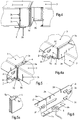
Fig. 1 ist die perspektivische Darstellung eines Teiles eines aus erfindungsgemäßen Profilen zusammengesetzten Regals wobei diese mittels erfindungsgemäßem System untereinander verbunden sind. - Die
Fig. 2 zeigt in perspektivischer Darstellung einen erfindungsgemäßen vertikalen Pfosten, teilweise in Schnittdarstellung, mit zwei daran freitragend befestigten horizontalen Elementen mit variierbarer Länge mit T-förmigem erfindungsgemäßen Querschnitt. - Die
Fig. 3 zeigt in perspektivischer Darstellung einen Teil eines inFig. 2 gezeigten Verbindungselements. - Die
Fig. 3a zeigt die Vorderansicht eines in denFig. 2 undFig. 3 gezeigten Verbindungselements, wobei einer der T-förmigen Teile mit durchgezogener Linie und der zweite T-förmige Teil mit strichlierter Linie dargestellt ist. - Die
Fig. 3b ist eine Draufsicht auf das rohrförmige Profil eines Pfostens mit einem in diesen eingesetzten T-förmigen Verbindungselement. - Die
Fig. 4 ist die perspektivische Darstellung des Verbindungsbereiches zwischen einer Ablage aus Blech mit einem T-förmigen Verbindungselement und des Einhängbereiches des Endes der besagten Ablage an einer anliegenden Ablage. - Die
Fig. 4a ist die perspektivische Darstellung des inFig. 4 gezeigten Verbindungs- und Einhängbereichs, gemäß einem anderen Betrachtungswinkel. - Die
Fig. 5 ist die perspektivische Darstellung eines Einhägbereiches zweier Ablagen aus Blech an einem horizontalen T-förmigen Verbindungselement mittels einem zweiseitig wirkenden Einhängelement. - Die
Fig. 5a ist die perspektivische Darstellung des Endbereiches eines zweiseitig wirkenden, inFig. 5 gezeigten, Einhängelements. - Die
Fig. 6 ist die perspektivische Darstellung der Anbringung eines Drucksensors an einem der horizontalen Flansche eines horizontalen Verbindungselements. - Die Struktur eines Regals ist erfindungsgemäß aus vertikalen Pfosten 1, an welchen mehrere horizontale Verbindungselemente oder freitragende Elemente 2 mit umgekehrt T-förmigem Querschnitt, zueinander vertikal beabstandet, einsetzbar und befestigbar sind, zusammengesetzt. An den besagten Verbindungselementen oder freitragenden Elementen 2 können horizontale Längsträger 4 und/oder horizontale Ablagen 3 angebracht werden.
- Um das Einhängen zwischen dem Pfosten 1 und dem horizontalen Element 2 auf, von außen, nicht sichtbarer und nicht der Ablagerung von Schmutz ausgesetzten, Weise und somit reinigungsfreundlich zu erreichen, schlägt die Erfindung vor, dass der rohrförmige Pfosten 1 zwei geradlinige, nach innen in den Querschnitt ragende und zueinander anliegende, bzw. zueinander um ein Maß beabstandete Schenkel 1a aufweist, wobei dieses Maß wesentlich der Stärke des Einhängendes 2i des horizontalen Vebindungselements oder des freitragenden Elements 2 entspricht. Die besagten Schenkel 1a weisen Langlöcher oder Durchbrüche 1c auf in welche sich Vorsprünge 2c einfügen und einhängen welche beidseitig vom Einhängende 2i des horizontalen Verbindungselements oder freitragenden Elements 2 mit T-förmigem Querschnitt abragen. Die Langlöcher oder Durchbrüche 1c können eine, sich nach unten, verengende Form aufweisen. Die am Einhängende 2i vorgesehenen Einhängvorsprünge 2c sind mindestens zwei, einer an der rechten und einer an der linken Seite, vorteilhafterweise sind es mehr als zwei um ein stabiles Einhängen zu erreichen und vorzugsweise kann ihre Position, in Bezug auf die Stirnfläche des Einhängendes 2i, derart angeordnet sein, dass diese Fläche an der Innenfläche des Pfostens 1 anliegt. Die Langlöcher 1c an den Schenkeln 1a des Pfostens 1 und/oder die Einhängvorsprünge 2c sind derart ausgeformt dass, während der Einhängbewegung am Verbindungselement 2, eine Kraftkomponente wirkt, welche die Tendenz hat, das Einhängende 2i nach innen des Querschnitts des Pfostens 1 zu ziehen und die beiden Schenkel 1a gegen das besagte zwischenliegende Einhängende 2i zu ziehen.
Gemäß einer Weiterentwicklung des Erfindungsgedankens kann, entsprechend dem Bereich der Abwinkelung der beiden Schenkel 1a des Pfostens nach innen des Querschnittes, wo diese einen Winkel von ca. 90° mit der Außenwand des Profils bilden, eine vertikale nach außen vorstehende Längsrippe 1b vorgesehen sein. Mit diesen äußeren Längsrippen 1b kann eine, stirnseitig an den horizontalen Flanschen 2b des Verbindungselements oder freitragenden Elements 2 vorgesehene, Kerbe 2g zusammenwirken. Diese Kerbe 2g und/oder der Querschnitt der Rippen 1b können erfindungsgemäß so ausgeformt sein, dass durch die Bewegung des Elementes 2 gegen den Pfosten 1, welche durch die Kraftkomponente während der Einhängbewegung zwischen dem Element 2 und dem Pfosten 1 bewirkt wird, eine Annäherung zwischen den beiden Rippen 1b und ein Zusammenziehen gegen den vertikalen Flansch des Einhängendes 2i erfolgt. - Erfindungsgemäß kann das Verbindungselement oder freitragende Element 2 mit T-förmigem Querschnitt von einfacher, z.B. durch Extrusion hergestellter Art oder von zusammengesetzter Art, bestehend aus zwei wesentlich identischen Elementen mit T-förmigem Querschnitt, in Längsrichtung verschiebbar zusammengesetzter Art sein. In diesem letzten Fall sind beide Elemente 2 durch Profilierung von Blech hergestellt, der vertikale Flansch ist einlagig, einer der horizontalen Flansche ist doppellagig sich überdeckend gebogen, während der zweite horizontale Flansch 2a einlagig ist. Indem an einem der Elemente 2, welche das Verbindungselement oder das freitragende Element bilden, der horizontale Flansch 2a zweilagig derartig ausgebildet ist, dass zwischen den Schenkeln ein Abstand entsprechend der Blechstärke eingehalten wird, ist der Zusammenbau beider Elemente mit T-förmigem Querschnitt durch Einschieben des einlagigen Flansches eines Elementes in den freien entsprechenden Zwischenraum des anderen Elements bis auf Anschlag der beiden vertikalen Flansche, möglich. Diese Ausführungsform macht es möglich entsprechende Längslanglöcher 2e an beiden zusammengefügten und durch die Löngslöcher 2e durchgreifende Bolzen 2f mit Köpfen an beiden Enden gesicherte Elementen 2 vorzusehen um dadurch eine Längsverschiebung zwischen beiden zusammengefügten Elementen 2, zwecks Veränderung der Längserstreckung zu erreichen. Die Erfindung schließt nicht aus, dass die beiden zusammengefügten Elemente 2, zwecks Ausbildung eines in Längserstreckung veränderbaren Verbindungselementes, durch einen einzigen durchgeifenden Bolzen so verbunden sind, dass eine Schwenkbewegung zwischen den beiden zusammengefügten Elementen möglich ist um dadurch, in gewissen Situationen, die Montage/Demontage an den Pfosten zu erleichtern.
- An den Verbindungselementen oder freitragenden Elementen 2 sind Ablagen 3 aus Blech mit umgebogenen Rändern anbringbar, welche an den Enden Einhängflansche 3a, 3b und/oder Einrastkerben 3c aufweisen. Diese Einhängflansche ermöglichen das direkte Einhängen am vertikalen Flansch 2a der Verbindungselemente oder freitragenden Elemente 2, bzw. das gegenseitige Einhängen zwischen zwei Enden zweier Ablagen 3. Die Einrastkerben 3c ermöglichen das direkte Einrasten an den vertikalen Flanschen 2a der Elemente 2, welche dafür mit entsprechenden Kerben 2d versehen sein können. Es können auch Elemente mit beidseitiger Einhängmöglichkeit 5 verwendet werden welche an den Elementen 2 mit beidseitig angeordneten Einhängflanschen 5a, zwecks Aufnahme der Einhängflansche 3a der Ablagen 3, angebracht werden.
- Erfindungsgemäß können an den Verbindungselementen oder freitragenden Elementen 2 Längsträger 4 mit z.B. U-förmigem oder rechteckigem rohrförmigem Querschnitt angebracht werden. Diese Längsträger können an ihren Enden mit Einhängzungen und/oder Einrastkerben, ähnlich wie jene an den Ablagen, versehen sein. Die Längsträger 4 können alternativ mit Einhängzungen versehen sein welche mit den Einhängenden 2i der Verbindungselemente oder freitragenden Elemente 2 identisch sind, aber um 90° verdreht zur Längserstreckung der Längsträger 4 angeordnet sind um an den Pfosten 1 zwischen deren Flansche 1a eingesetzt werden zu können.
- Erfindungsgemäß können zwischen den Verbindungselementen 2 und den daran angebrachten Ablagen bekannte Sensoren 6 angebracht werden um Gewichtsveränderungen an den Ablagen anzeigen zu können.
Claims (10)
- Profile für den Zusammenbau tragender Strukturen bestehend aus Pfosten (1), Verbindungselementen oder freitragenden Elementen (2), Längsträgern (4) und/oder aus Ablagen (3) welche an den Verbindungselementen oder freitragenden Elementen (2) oder an den Längsträgern (4) anbringbar sind, wobei die Pfosten einen rechteckigen Querschnitt aufweisen welcher aus einem U-förmigen Querschnitt mit den vom Verbindungsflansch parallel abstehenden, ins Innere des Querschnittes ragenden, sich zueinander parallel in Längsrichtung des Pfostens erstreckenden Schenkeln (1a) geformt ist, dadurch gekennzeichnet, dass die Schenkel (1a) der Pfosten (1) aneinander anliegen oder voneinander um ein Maß beabstandet sind welches der Stärke des Einhängendes (2i), ohne Einhängvorsprünge, des am Pfosten anbringbaren Verbindungselementes oder des freitragenden Elementes (2) entspricht, dass beide der besagten Schenkel (1a) Langlöcher oder Durchbrüche (1c) aufweisen welche sich an beiden Schenkeln betreffend die Form und Anordnung entsprechen und dass das Einhängende (2i) des Verbindungselements oder freitragenden Elements (2) mit beidseitig abragenden Einhängvorsprüngen (2c) versehen ist welche derart ausgeformt sind dass diese, bei zwischen den elastisch spreizbaren Schenkeln (1a) des Pfosten (1) eingeführten Einhängenden (2i), in die an beiden Schenkeln (1a) vorgesehenen Langlöcher oder Durchbrüche (1c) eindringen um sich, infolge einer Verschiebung nach unten, gemäß der Längserstreckung des Pfostens, an den Schenkeln (1a) einzuhängen.
- Profile gemäß Anspruch 1, dadurch gekennzeichnet, dass die Stärke der Schenkel (1a), im Bereich der Langlöcher oder Durchbrüche (1c), mindestens im Wirkungsbereich der Einhängvorsprünge (2c), als Einleitbereich mit Abschrägung ausgeformt sind und/oder dass die Wand der Schenkel im selben Bereich als Anzug ausgeformt ist.
- Profile gemäß Anspruch 1, dadurch gekennzeichnet, dass die Langlöcher oder Durchbrüche (1c) an den Schenkeln (1a) des Pfostens (1) eine nach unten sich verengende Form aufweisen.
- Profile gemäß Anspruch 1, dadurch gekennzeichnet, dass das Verbindungselement oder freitragende Element (2) einen umgekehrten T-förmigen Querschnitt aufweist und dass der vertikale Flansch (2a) mit seinem Endbereich, ohne horizontal abstehenden Flanschen (2b) als, mit Einhängvorsprüngen versehenes, Einhängende (2i) wirkt.
- Profile gemäß Anspruch 1, dadurch gekennzeichnet, dass das Verbindungselement oder freitragende Element (2) aus zwei zusammengefügten, wesentlich identischen, aus Blech hergestellten Elementen mit umgekehrtem T-förmigen Querschnitt besteht, so dass einer der horizontalen Flansche (2b) doppellagig und der andere einlagig ist, dass an einem der besagten T-förmigen am doppellagigen Flansch die Blechschenkel nicht gegenseitig anliegen sondern um ein Maß beabstandet sind welches der Blechstärke entspricht, so dass dieser Flansch den einlagigen Flansch des zweiten T-förmigen Teiles aufnehmen kann, welcher in zusammengefügter Position mit seinem vertikalen Flansch (2a) am entsprechenden vertikalen Flansch des zweiten T-förmigen Elementes anliegt und dass beide zusammengefügten Teile mit entsprechenden Langlöchern (2e) versehen sind und durch, diese Langlöcher durchgreifende, Bolzen (2f) zusammengehalten sind um ein gegenseitiges Verschieben der beiden Teile in Längsrichtung zu ermöglichen.
- Profile gemäß Anspruch 1, dadurch gekennzeichnet, dass die Form der Einhängvorsprünge (2c), welche am Einhängende (2i) des Verbindungselements oder freitragenden Elements (2) vorgesehen sind, sich gegen unten verschmälern und dass die Flächen der selben Einhängvorsprünge welche an den, mit Langlöchern oder Durchbrüchen (1c) versehenen, Schenkeln (1a) des Pfostens (1) wirken, mit spitzem Winkel gegen die Einhängfläche der Einhängvorsprünge angewinkelt sind.
- Profile gemäß Anspruch 1, dadurch gekennzeichnet, dass das Profil des Pfostens (1), im Bereich beider nach innen ragenden Schenkel (1a), eine nach außen vorstehende Rippe (1b) aufweist, dass an diesen Rippen (1b), während dem Einhängen des Verbindungselements oder freitragenden Elements (2), am Pfosten (1) eine Kerbe (2g) wirkt welche stirnseitig an den horizontalen Flanschen (2b) des Verbindungselements oder freitragenden Elements (2) vorgesehen ist, wobei diese Flanschen gegen das Einhängende (2i) des besagten Verbindungselements (2) gedrückt werden.
- Profile gemäß Anspruch 1, dadurch gekennzeichnet, dass die Längsträger (4) und die Ablagen (3) an den Enden mit Einhängrändern (3a, 3b) für das direkte Einhängen an den Verbindungselementen oder freitragenden Elementen (2) oder für das Einhängen mit Zwischenlage zweiseitiger Einhängelemente (5) versehen sind.
- Profile gemäß Anspruch 1, dadurch gekennzeichnet, dass die Längsträger (4) mit Einhängenden (2i) versehen sind welche in einem Winkel von 90° zur Längserstreckung der Längsträger abstehen.
- Kupplungs- und Verbindungssystem zwischen Pfosten (1) und Verbindungselemente oder freitragende Elemente (2) gemäß den in den Ansprüchen 1 bis 7 beschriebenen Merkmalen, dadurch gekennzeichnet, dass durch Einsetzen des Einhängendes (2i) zwischen den Schenkeln (1a) des Pfostens (1) diese durch den Vorstand der Einhängvorsprünge (2c) leicht gespreizt werden und ihre zueinander parallele Lage, infolge des Eindringens der besagten Einhängvorsprünge (2c) in die entsprechenden Langlöcher oder Durchbrüche (1c) an den Schenkeln (1a) des Pfostens, einnehmen und dass der Einhängvorgang durch das Verschieben des Verbindungselementes oder freitragenden Elementes (2), nach unten, gemäß Längserstreckung des Pfostens abgeschlossen wird.
Applications Claiming Priority (1)
| Application Number | Priority Date | Filing Date | Title |
|---|---|---|---|
| IT102018000002975A IT201800002975A1 (it) | 2018-02-23 | 2018-02-23 | Profilati per la composizione di strutture portanti e sistema di accoppiamento e giunzione fra essi |
Publications (2)
| Publication Number | Publication Date |
|---|---|
| EP3530146A1 true EP3530146A1 (de) | 2019-08-28 |
| EP3530146B1 EP3530146B1 (de) | 2021-06-02 |
Family
ID=62167798
Family Applications (1)
| Application Number | Title | Priority Date | Filing Date |
|---|---|---|---|
| EP19000093.5A Active EP3530146B1 (de) | 2018-02-23 | 2019-02-20 | Profile und strukturelemente für den bau tragender strukturen |
Country Status (2)
| Country | Link |
|---|---|
| EP (1) | EP3530146B1 (de) |
| IT (1) | IT201800002975A1 (de) |
Cited By (1)
| Publication number | Priority date | Publication date | Assignee | Title |
|---|---|---|---|---|
| SE1951398A1 (en) * | 2019-12-05 | 2021-06-06 | Ikea Supply Ag | A support bracket, an elongated support member and a goods storage system |
Citations (2)
| Publication number | Priority date | Publication date | Assignee | Title |
|---|---|---|---|---|
| GB2048351A (en) * | 1979-03-26 | 1980-12-10 | Haines K W | Furniture frameworks |
| EP0151902A2 (de) * | 1984-02-13 | 1985-08-21 | Brennwald, Erwin | Gelochter Profilstab aus Metall |
Family Cites Families (1)
| Publication number | Priority date | Publication date | Assignee | Title |
|---|---|---|---|---|
| DE3401125A1 (de) * | 1984-01-14 | 1985-07-18 | Walter Dr.-Ing. 5100 Aachen Jürgens | Profil |
-
2018
- 2018-02-23 IT IT102018000002975A patent/IT201800002975A1/it unknown
-
2019
- 2019-02-20 EP EP19000093.5A patent/EP3530146B1/de active Active
Patent Citations (2)
| Publication number | Priority date | Publication date | Assignee | Title |
|---|---|---|---|---|
| GB2048351A (en) * | 1979-03-26 | 1980-12-10 | Haines K W | Furniture frameworks |
| EP0151902A2 (de) * | 1984-02-13 | 1985-08-21 | Brennwald, Erwin | Gelochter Profilstab aus Metall |
Cited By (4)
| Publication number | Priority date | Publication date | Assignee | Title |
|---|---|---|---|---|
| SE1951398A1 (en) * | 2019-12-05 | 2021-06-06 | Ikea Supply Ag | A support bracket, an elongated support member and a goods storage system |
| WO2021112752A1 (en) * | 2019-12-05 | 2021-06-10 | Ikea Supply Ag | An elongated support member and a goods storage system |
| SE544867C2 (en) * | 2019-12-05 | 2022-12-13 | Ikea Supply Ag | An elongated support member and a goods storage system |
| US12102230B2 (en) | 2019-12-05 | 2024-10-01 | Ikea Supply Ag | Elongated support member and a goods storage system |
Also Published As
| Publication number | Publication date |
|---|---|
| EP3530146B1 (de) | 2021-06-02 |
| IT201800002975A1 (it) | 2019-08-23 |
Similar Documents
| Publication | Publication Date | Title |
|---|---|---|
| DE2502992A1 (de) | Bodenplatte | |
| EP3530146B1 (de) | Profile und strukturelemente für den bau tragender strukturen | |
| EP3137704B1 (de) | Befestigungssystem für gebäudefassaden und seine verwendung | |
| EP3262988B1 (de) | Regalsystem | |
| DE3688113T2 (de) | Elementensatz fuer die einrichtung von ausstellungsraeumen, geschaeften und anderen orten. | |
| DE69806697T2 (de) | Lagergestell mit Profilelementen und Befestigungsmitteln der Elemente | |
| DE10044969A1 (de) | Wandprofilleiste | |
| EP0947151A2 (de) | Regal | |
| WO2010141970A1 (de) | Wandverkleidung | |
| EP2324732A1 (de) | Lagerregal, insbesondere automatisches Kleinteilelager | |
| DE29508050U1 (de) | Verkleidungssystem | |
| DE2609100C2 (de) | Bausatz für die Herstellung von Regalen variabler Größe | |
| DE1178564B (de) | Metallmoebel, z. B. Regal oder Schrank | |
| DE202007001060U1 (de) | Modulares Wandregal | |
| EP1408793B1 (de) | Regalsystem | |
| EP2684820A1 (de) | Lagerregal | |
| EP3685705B1 (de) | Betriebseinrichtung mit zwei profilen und einer wand | |
| WO2018028844A1 (de) | Profilbauteil und möbelsystem mit einem solchen profilbauteil | |
| EP0052774B1 (de) | Schrank- oder Gestellkörper | |
| EP1169946A1 (de) | Profile und Verbindungssystem für die Zusammensetzung von tragenden Strukturen | |
| DE102009009236A1 (de) | Regalsystem | |
| DE19940168C2 (de) | Aus Blech hergestelltes Plattenelement | |
| DE19835112A1 (de) | Regal | |
| EP2213200B1 (de) | Regalschiene und Regal mit einer solchen Regalschiene | |
| DE1779089C (de) | Zerlegbares Regal, welches Stützen und Querträger sowie an den Rändern abgekantete Regalböden aufweist und bei dem jede Stütze aus einem im Querschnitt T-förmigen Hohlprofil gebildet ist |
Legal Events
| Date | Code | Title | Description |
|---|---|---|---|
| PUAI | Public reference made under article 153(3) epc to a published international application that has entered the european phase |
Free format text: ORIGINAL CODE: 0009012 |
|
| STAA | Information on the status of an ep patent application or granted ep patent |
Free format text: STATUS: THE APPLICATION HAS BEEN PUBLISHED |
|
| AK | Designated contracting states |
Kind code of ref document: A1 Designated state(s): AL AT BE BG CH CY CZ DE DK EE ES FI FR GB GR HR HU IE IS IT LI LT LU LV MC MK MT NL NO PL PT RO RS SE SI SK SM TR |
|
| AX | Request for extension of the european patent |
Extension state: BA ME |
|
| STAA | Information on the status of an ep patent application or granted ep patent |
Free format text: STATUS: REQUEST FOR EXAMINATION WAS MADE |
|
| 17P | Request for examination filed |
Effective date: 20200214 |
|
| STAA | Information on the status of an ep patent application or granted ep patent |
Free format text: STATUS: EXAMINATION IS IN PROGRESS |
|
| 17Q | First examination report despatched |
Effective date: 20200407 |
|
| RIC1 | Information provided on ipc code assigned before grant |
Ipc: A47B 96/14 20060101ALI20200806BHEP Ipc: A47B 47/02 20060101ALN20200806BHEP Ipc: F16B 12/38 20060101ALI20200806BHEP Ipc: A47B 57/48 20060101AFI20200806BHEP |
|
| RIC1 | Information provided on ipc code assigned before grant |
Ipc: A47B 47/02 20060101ALN20200902BHEP Ipc: F16B 12/38 20060101ALI20200902BHEP Ipc: A47B 96/14 20060101ALI20200902BHEP Ipc: A47B 57/48 20060101AFI20200902BHEP |
|
| RIC1 | Information provided on ipc code assigned before grant |
Ipc: A47B 57/48 20060101AFI20201110BHEP Ipc: A47B 96/14 20060101ALI20201110BHEP Ipc: A47B 47/02 20060101ALN20201110BHEP Ipc: F16B 12/38 20060101ALI20201110BHEP |
|
| RIC1 | Information provided on ipc code assigned before grant |
Ipc: A47B 47/02 20060101ALN20201202BHEP Ipc: F16B 12/38 20060101ALI20201202BHEP Ipc: A47B 96/14 20060101ALI20201202BHEP Ipc: A47B 57/48 20060101AFI20201202BHEP |
|
| RIC1 | Information provided on ipc code assigned before grant |
Ipc: A47B 47/02 20060101ALN20201208BHEP Ipc: A47B 57/48 20060101AFI20201208BHEP Ipc: A47B 96/14 20060101ALI20201208BHEP Ipc: F16B 12/38 20060101ALI20201208BHEP |
|
| GRAP | Despatch of communication of intention to grant a patent |
Free format text: ORIGINAL CODE: EPIDOSNIGR1 |
|
| STAA | Information on the status of an ep patent application or granted ep patent |
Free format text: STATUS: GRANT OF PATENT IS INTENDED |
|
| INTG | Intention to grant announced |
Effective date: 20210115 |
|
| RIC1 | Information provided on ipc code assigned before grant |
Ipc: A47B 47/02 20060101ALN20201218BHEP Ipc: F16B 12/38 20060101ALI20201218BHEP Ipc: A47B 57/48 20060101AFI20201218BHEP Ipc: A47B 96/14 20060101ALI20201218BHEP |
|
| GRAS | Grant fee paid |
Free format text: ORIGINAL CODE: EPIDOSNIGR3 |
|
| GRAA | (expected) grant |
Free format text: ORIGINAL CODE: 0009210 |
|
| STAA | Information on the status of an ep patent application or granted ep patent |
Free format text: STATUS: THE PATENT HAS BEEN GRANTED |
|
| REG | Reference to a national code |
Ref country code: CH Ref legal event code: EP |
|
| AK | Designated contracting states |
Kind code of ref document: B1 Designated state(s): AL AT BE BG CH CY CZ DE DK EE ES FI FR GB GR HR HU IE IS IT LI LT LU LV MC MK MT NL NO PL PT RO RS SE SI SK SM TR |
|
| REG | Reference to a national code |
Ref country code: GB Ref legal event code: FG4D Free format text: NOT ENGLISH |
|
| REG | Reference to a national code |
Ref country code: AT Ref legal event code: REF Ref document number: 1397635 Country of ref document: AT Kind code of ref document: T Effective date: 20210615 |
|
| REG | Reference to a national code |
Ref country code: IE Ref legal event code: FG4D Free format text: LANGUAGE OF EP DOCUMENT: GERMAN |
|
| REG | Reference to a national code |
Ref country code: DE Ref legal event code: R096 Ref document number: 502019001511 Country of ref document: DE |
|
| REG | Reference to a national code |
Ref country code: LT Ref legal event code: MG9D |
|
| PG25 | Lapsed in a contracting state [announced via postgrant information from national office to epo] |
Ref country code: BG Free format text: LAPSE BECAUSE OF FAILURE TO SUBMIT A TRANSLATION OF THE DESCRIPTION OR TO PAY THE FEE WITHIN THE PRESCRIBED TIME-LIMIT Effective date: 20210902 Ref country code: FI Free format text: LAPSE BECAUSE OF FAILURE TO SUBMIT A TRANSLATION OF THE DESCRIPTION OR TO PAY THE FEE WITHIN THE PRESCRIBED TIME-LIMIT Effective date: 20210602 Ref country code: LT Free format text: LAPSE BECAUSE OF FAILURE TO SUBMIT A TRANSLATION OF THE DESCRIPTION OR TO PAY THE FEE WITHIN THE PRESCRIBED TIME-LIMIT Effective date: 20210602 Ref country code: HR Free format text: LAPSE BECAUSE OF FAILURE TO SUBMIT A TRANSLATION OF THE DESCRIPTION OR TO PAY THE FEE WITHIN THE PRESCRIBED TIME-LIMIT Effective date: 20210602 |
|
| REG | Reference to a national code |
Ref country code: NL Ref legal event code: MP Effective date: 20210602 |
|
| PG25 | Lapsed in a contracting state [announced via postgrant information from national office to epo] |
Ref country code: GR Free format text: LAPSE BECAUSE OF FAILURE TO SUBMIT A TRANSLATION OF THE DESCRIPTION OR TO PAY THE FEE WITHIN THE PRESCRIBED TIME-LIMIT Effective date: 20210903 Ref country code: SE Free format text: LAPSE BECAUSE OF FAILURE TO SUBMIT A TRANSLATION OF THE DESCRIPTION OR TO PAY THE FEE WITHIN THE PRESCRIBED TIME-LIMIT Effective date: 20210602 Ref country code: RS Free format text: LAPSE BECAUSE OF FAILURE TO SUBMIT A TRANSLATION OF THE DESCRIPTION OR TO PAY THE FEE WITHIN THE PRESCRIBED TIME-LIMIT Effective date: 20210602 Ref country code: NO Free format text: LAPSE BECAUSE OF FAILURE TO SUBMIT A TRANSLATION OF THE DESCRIPTION OR TO PAY THE FEE WITHIN THE PRESCRIBED TIME-LIMIT Effective date: 20210902 Ref country code: LV Free format text: LAPSE BECAUSE OF FAILURE TO SUBMIT A TRANSLATION OF THE DESCRIPTION OR TO PAY THE FEE WITHIN THE PRESCRIBED TIME-LIMIT Effective date: 20210602 Ref country code: PL Free format text: LAPSE BECAUSE OF FAILURE TO SUBMIT A TRANSLATION OF THE DESCRIPTION OR TO PAY THE FEE WITHIN THE PRESCRIBED TIME-LIMIT Effective date: 20210602 |
|
| PG25 | Lapsed in a contracting state [announced via postgrant information from national office to epo] |
Ref country code: PT Free format text: LAPSE BECAUSE OF FAILURE TO SUBMIT A TRANSLATION OF THE DESCRIPTION OR TO PAY THE FEE WITHIN THE PRESCRIBED TIME-LIMIT Effective date: 20211004 Ref country code: NL Free format text: LAPSE BECAUSE OF FAILURE TO SUBMIT A TRANSLATION OF THE DESCRIPTION OR TO PAY THE FEE WITHIN THE PRESCRIBED TIME-LIMIT Effective date: 20210602 Ref country code: RO Free format text: LAPSE BECAUSE OF FAILURE TO SUBMIT A TRANSLATION OF THE DESCRIPTION OR TO PAY THE FEE WITHIN THE PRESCRIBED TIME-LIMIT Effective date: 20210602 Ref country code: SM Free format text: LAPSE BECAUSE OF FAILURE TO SUBMIT A TRANSLATION OF THE DESCRIPTION OR TO PAY THE FEE WITHIN THE PRESCRIBED TIME-LIMIT Effective date: 20210602 Ref country code: CZ Free format text: LAPSE BECAUSE OF FAILURE TO SUBMIT A TRANSLATION OF THE DESCRIPTION OR TO PAY THE FEE WITHIN THE PRESCRIBED TIME-LIMIT Effective date: 20210602 Ref country code: SK Free format text: LAPSE BECAUSE OF FAILURE TO SUBMIT A TRANSLATION OF THE DESCRIPTION OR TO PAY THE FEE WITHIN THE PRESCRIBED TIME-LIMIT Effective date: 20210602 Ref country code: EE Free format text: LAPSE BECAUSE OF FAILURE TO SUBMIT A TRANSLATION OF THE DESCRIPTION OR TO PAY THE FEE WITHIN THE PRESCRIBED TIME-LIMIT Effective date: 20210602 Ref country code: ES Free format text: LAPSE BECAUSE OF FAILURE TO SUBMIT A TRANSLATION OF THE DESCRIPTION OR TO PAY THE FEE WITHIN THE PRESCRIBED TIME-LIMIT Effective date: 20210602 |
|
| REG | Reference to a national code |
Ref country code: DE Ref legal event code: R097 Ref document number: 502019001511 Country of ref document: DE |
|
| PLBE | No opposition filed within time limit |
Free format text: ORIGINAL CODE: 0009261 |
|
| STAA | Information on the status of an ep patent application or granted ep patent |
Free format text: STATUS: NO OPPOSITION FILED WITHIN TIME LIMIT |
|
| PG25 | Lapsed in a contracting state [announced via postgrant information from national office to epo] |
Ref country code: DK Free format text: LAPSE BECAUSE OF FAILURE TO SUBMIT A TRANSLATION OF THE DESCRIPTION OR TO PAY THE FEE WITHIN THE PRESCRIBED TIME-LIMIT Effective date: 20210602 |
|
| 26N | No opposition filed |
Effective date: 20220303 |
|
| PG25 | Lapsed in a contracting state [announced via postgrant information from national office to epo] |
Ref country code: AL Free format text: LAPSE BECAUSE OF FAILURE TO SUBMIT A TRANSLATION OF THE DESCRIPTION OR TO PAY THE FEE WITHIN THE PRESCRIBED TIME-LIMIT Effective date: 20210602 |
|
| REG | Reference to a national code |
Ref country code: DE Ref legal event code: R119 Ref document number: 502019001511 Country of ref document: DE |
|
| PG25 | Lapsed in a contracting state [announced via postgrant information from national office to epo] |
Ref country code: MC Free format text: LAPSE BECAUSE OF FAILURE TO SUBMIT A TRANSLATION OF THE DESCRIPTION OR TO PAY THE FEE WITHIN THE PRESCRIBED TIME-LIMIT Effective date: 20210602 |
|
| REG | Reference to a national code |
Ref country code: BE Ref legal event code: MM Effective date: 20220228 |
|
| PG25 | Lapsed in a contracting state [announced via postgrant information from national office to epo] |
Ref country code: LU Free format text: LAPSE BECAUSE OF NON-PAYMENT OF DUE FEES Effective date: 20220220 |
|
| PG25 | Lapsed in a contracting state [announced via postgrant information from national office to epo] |
Ref country code: FR Free format text: LAPSE BECAUSE OF NON-PAYMENT OF DUE FEES Effective date: 20220228 |
|
| PG25 | Lapsed in a contracting state [announced via postgrant information from national office to epo] |
Ref country code: IE Free format text: LAPSE BECAUSE OF NON-PAYMENT OF DUE FEES Effective date: 20220220 Ref country code: DE Free format text: LAPSE BECAUSE OF NON-PAYMENT OF DUE FEES Effective date: 20220901 |
|
| PG25 | Lapsed in a contracting state [announced via postgrant information from national office to epo] |
Ref country code: BE Free format text: LAPSE BECAUSE OF NON-PAYMENT OF DUE FEES Effective date: 20220228 |
|
| GBPC | Gb: european patent ceased through non-payment of renewal fee |
Effective date: 20230220 |
|
| PG25 | Lapsed in a contracting state [announced via postgrant information from national office to epo] |
Ref country code: GB Free format text: LAPSE BECAUSE OF NON-PAYMENT OF DUE FEES Effective date: 20230220 |
|
| PG25 | Lapsed in a contracting state [announced via postgrant information from national office to epo] |
Ref country code: GB Free format text: LAPSE BECAUSE OF NON-PAYMENT OF DUE FEES Effective date: 20230220 |
|
| PGFP | Annual fee paid to national office [announced via postgrant information from national office to epo] |
Ref country code: AT Payment date: 20240228 Year of fee payment: 6 |
|
| PG25 | Lapsed in a contracting state [announced via postgrant information from national office to epo] |
Ref country code: MK Free format text: LAPSE BECAUSE OF FAILURE TO SUBMIT A TRANSLATION OF THE DESCRIPTION OR TO PAY THE FEE WITHIN THE PRESCRIBED TIME-LIMIT Effective date: 20210602 Ref country code: CY Free format text: LAPSE BECAUSE OF FAILURE TO SUBMIT A TRANSLATION OF THE DESCRIPTION OR TO PAY THE FEE WITHIN THE PRESCRIBED TIME-LIMIT Effective date: 20210602 |
|
| PGFP | Annual fee paid to national office [announced via postgrant information from national office to epo] |
Ref country code: CH Payment date: 20240301 Year of fee payment: 6 |
|
| PG25 | Lapsed in a contracting state [announced via postgrant information from national office to epo] |
Ref country code: HU Free format text: LAPSE BECAUSE OF FAILURE TO SUBMIT A TRANSLATION OF THE DESCRIPTION OR TO PAY THE FEE WITHIN THE PRESCRIBED TIME-LIMIT; INVALID AB INITIO Effective date: 20190220 |
|
| PGFP | Annual fee paid to national office [announced via postgrant information from national office to epo] |
Ref country code: IT Payment date: 20240226 Year of fee payment: 6 |
|
| PG25 | Lapsed in a contracting state [announced via postgrant information from national office to epo] |
Ref country code: TR Free format text: LAPSE BECAUSE OF FAILURE TO SUBMIT A TRANSLATION OF THE DESCRIPTION OR TO PAY THE FEE WITHIN THE PRESCRIBED TIME-LIMIT Effective date: 20210602 |
|
| PG25 | Lapsed in a contracting state [announced via postgrant information from national office to epo] |
Ref country code: MT Free format text: LAPSE BECAUSE OF FAILURE TO SUBMIT A TRANSLATION OF THE DESCRIPTION OR TO PAY THE FEE WITHIN THE PRESCRIBED TIME-LIMIT Effective date: 20210602 |