EP3527101A1 - Dispositif horloger de type habillage à composants mobiles - Google Patents
Dispositif horloger de type habillage à composants mobiles Download PDFInfo
- Publication number
- EP3527101A1 EP3527101A1 EP18157057.3A EP18157057A EP3527101A1 EP 3527101 A1 EP3527101 A1 EP 3527101A1 EP 18157057 A EP18157057 A EP 18157057A EP 3527101 A1 EP3527101 A1 EP 3527101A1
- Authority
- EP
- European Patent Office
- Prior art keywords
- component
- guide element
- guide
- watch device
- watchmaking
- Prior art date
- Legal status (The legal status is an assumption and is not a legal conclusion. Google has not performed a legal analysis and makes no representation as to the accuracy of the status listed.)
- Granted
Links
Images



Classifications
-
- A—HUMAN NECESSITIES
- A44—HABERDASHERY; JEWELLERY
- A44C—PERSONAL ADORNMENTS, e.g. JEWELLERY; COINS
- A44C5/00—Bracelets; Wrist-watch straps; Fastenings for bracelets or wrist-watch straps
- A44C5/02—Link constructions
- A44C5/04—Link constructions extensible
- A44C5/08—Link constructions extensible having separate links
-
- A—HUMAN NECESSITIES
- A44—HABERDASHERY; JEWELLERY
- A44C—PERSONAL ADORNMENTS, e.g. JEWELLERY; COINS
- A44C5/00—Bracelets; Wrist-watch straps; Fastenings for bracelets or wrist-watch straps
- A44C5/02—Link constructions
-
- A—HUMAN NECESSITIES
- A44—HABERDASHERY; JEWELLERY
- A44C—PERSONAL ADORNMENTS, e.g. JEWELLERY; COINS
- A44C5/00—Bracelets; Wrist-watch straps; Fastenings for bracelets or wrist-watch straps
- A44C5/0053—Flexible straps
-
- A—HUMAN NECESSITIES
- A44—HABERDASHERY; JEWELLERY
- A44C—PERSONAL ADORNMENTS, e.g. JEWELLERY; COINS
- A44C5/00—Bracelets; Wrist-watch straps; Fastenings for bracelets or wrist-watch straps
- A44C5/18—Fasteners for straps, chains or the like
- A44C5/22—Fasteners for straps, chains or the like for closed straps
- A44C5/24—Fasteners for straps, chains or the like for closed straps with folding devices
- A44C5/246—Fasteners for straps, chains or the like for closed straps with folding devices having size adjusting means
-
- G—PHYSICS
- G04—HOROLOGY
- G04B—MECHANICALLY-DRIVEN CLOCKS OR WATCHES; MECHANICAL PARTS OF CLOCKS OR WATCHES IN GENERAL; TIME PIECES USING THE POSITION OF THE SUN, MOON OR STARS
- G04B37/00—Cases
- G04B37/22—Materials or processes of manufacturing pocket watch or wrist watch cases
- G04B37/225—Non-metallic cases
-
- G—PHYSICS
- G04—HOROLOGY
- G04B—MECHANICALLY-DRIVEN CLOCKS OR WATCHES; MECHANICAL PARTS OF CLOCKS OR WATCHES IN GENERAL; TIME PIECES USING THE POSITION OF THE SUN, MOON OR STARS
- G04B37/00—Cases
- G04B37/0008—Cases for pocket watches and wrist watches
Definitions
- the present invention relates to a clock device comprising at least two components movable relative to each other.
- This watch device can be a clasp for a bracelet or a bracelet or any watchmaking device.
- the invention also relates to a watch as such comprising such a watch device.
- a watch device comprises two components movable relative to each other.
- a clasp is generally provided with a device for adjusting the length of a bracelet.
- a device for adjusting the length of a bracelet may comprise a link or a mobile mesh relative to a lid of the clasp, which can occupy several different stable positions within the clasp, corresponding to different lengths of the bracelet.
- a bracelet mesh is adjustable thanks to a structure in two half stitches movable relative to each other.
- a watchmaking device often comprises two moving components.
- the general object of the invention is to provide a solution that best meets the aforementioned constraints.
- a first object of the invention is to provide a guiding solution for moving components of a watch device, to limit the wear of the guide elements, to reduce their friction, to reduce the risk of seizure and their corrosion.
- a second object of the invention is to provide a guiding solution for mobile components of a watch device for limiting or even preventing the deposition and / or amalgam of soiling in the guide elements. .
- a third object of the invention is to provide a guiding solution for mobile components of a watch device which improves the comfort of the user.
- the invention is based on a clock device, in particular a clock dressing device, comprising two components connected together, the first component comprising a first guide element and the second component comprising a second guide element, the two components.
- components being movably connected together by a cooperation of their respective guide elements, characterized in that the first guide element comprises a guide surface in at least partial contact with the second guide element, said guide surface comprising a polymeric material belonging to the family of polyaryletherketones (PAEK).
- PAEK polyaryletherketones
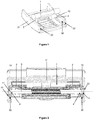
- the first embodiment of the invention is based on a watch device for adjusting the length of a bracelet within a clasp, as represented by the Figures 1 and 2 .
- a clock device comprises a first component 1, which is a link in this first embodiment, mounted movably relative to a second component 21, which is a clasp cover.
- the first component 1 of the watchmaking device comprises two extensional side meshes 2 arranged movably in rotation about a bar 3.
- the ends of this bar 3 comprise first guide elements 10, which are positioned in a slide of the clasp cover.
- the second component 21 of the watch device according to this first embodiment is a clasp cover comprising two side walls 22 each comprising a slide, as mentioned above. Each slide forms a second guide element 30, which cooperates with a first guide element 10.
- the first guide element 10 is advantageously in the form of a pad or a roller and the second guide element 30 in the form of a slide or a slide, or a bore, shaped to receive such a pad.
- the pads arranged at each end of the bar 3 thus slide parallel, in their respective opposite rails, in a movement substantially corresponding to a translation.
- the first guide element 10 is in the form of an element distinct from the first component 1.
- two pads with slightly arched profiles are disposed respectively on either side of the link comprising two side extension meshes 2, and are joined to these extension meshes by means of the bar 3.
- the runners comprise a central bore 11 provided for their positioning around a cylindrical receiving zone 4 to 1. end of the bar 3, as is particularly visible on the figure 2 .
- the first guide elements 10 that is to say the pads or rollers, are monobloc.
- they are entirely composed of a high performance polymer, belonging to the family of polyaryletherketones (PAEK), especially polyetheretherketone (PEEK).
- PAEK polyaryletherketones
- PEEK polyetheretherketone
- the first guide elements 10 could only comprise a portion of a high performance polymer, belonging to the family of polyaryletherketones (PAEK), including PEEK.
- this portion could be at a guide surface intended to come into contact with the second guide element 30, that is to say the slide.
- This portion can thus take the form of a surface coating at the contact zones or friction zones.
- a PEEK conformation can be overmolded on a pad.
- the first guide element 10 may comprise a core coated with a coating comprising the polymeric material belonging to the PEAK family, forming all or part of the guide surface.
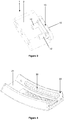
- the figure 3 represents an alternative embodiment in which a component comprising the first guide element 10 is directly attached to the first component 1.
- this component comprises fastening studs 12 on a lateral face, intended to be driven into bores of the first component. a lateral mesh 2 extension of the first component 1.
- This attachment can, for example, be implemented by driving, riveting, gluing, welding or brazing.
- This component comprises the guide element 10, which comprises a guide surface 13, on its second lateral face.
- the figure 5 illustrates a first component 1 according to an alternative embodiment.
- This first component 1 comprises a mesh 2 which comprises a projection, in particular a circular or oblong projection, which acts as a pad.
- This circular projection is formed on a sidewall of said mesh 2 and forms the guide element 10 of the first component.
- the mesh 2 is monoblock, namely that it is made of a high performance polymer, in particular a polymeric material belonging to the family of polyaryletherketones (PAEK), in particular PEEK.
- PAEK polyaryletherketones
- the projection may be overmolded on a side of the mesh 2.
- the projection may be coated with PEAK, for example PEEK, over all or part of its surface.
- the first embodiment has been described from a first component 1 comprising a guide element 10 at least partially composed of a material belonging to the family of polyaryletherketones (PAEK).
- a guide element 30 of the second component 21 could also comprise a material belonging to the polyaryletherketone (PAEK) family.
- any of the two mobile components of the watch device may comprise in whole or in part a material belonging to the family of polyaryletherketones (PAEK) on all or part of its guiding surface.
- the two mobile components of the watch device may comprise such a material.
- the second guide member 30 may be made of steel or precious material, such as gold or platinum.
- the second guide member 30 may be made of ceramic. More particularly, it may come from material with a component made of ceramic or steel or precious material, such as gold or platinum.
- the second guide element 30 may alternatively be made of a high performance polymer, in particular a polymeric material belonging to the family of polyaryletherketones (PAEK), in particular PEEK. More particularly, it may have come from a second mobile component entirely made of PEEK.
- PAEK polyaryletherketones
- the second guide element 30 may be attached to a component preferably made of steel or precious material such as gold or platinum.
- the second guide element 30 may be attached to a component made of ceramic.
- the figure 6 illustrates a clasp cover with slides disposed in side walls on either side of said lid, similarly to the first embodiment described above.
- the lid is monobloc, entirely composed of a high performance polymer, especially PEEK.
- the slides may be coated with a polymer material belonging to the family of polyaryletherketones (PAEK), including PEEK, on all or part of their surface.
- PAEK polyaryletherketones
- the watch device is a bracelet extension device for a clasp. It applies to any watchmaking device, in particular watchmaking, in which a second component is shaped to accommodate within it a guide element of a first component, such as a roller or a pad.
- a second component can thus, for example, include a cutout, such as a bore or a groove. This cut can be open or not.
- the relative movement of the two components of the watch device is advantageously a translation, possibly a slightly curved sliding, which can in particular correspond to the curvature of a clasp cover.
- this displacement could be an articulation such as a rotation for example.
- a guiding element of a mobile component may be any means allowing the relative displacement of a first component 1 relative to a second component 21.
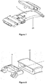
- the first component 1 may be a clasp blade, arranged to move substantially in translation relative to a second clasp blade, representing a second component 21, like the clasp blades described in the document EP0350785 .
- the first component 1 may be in the form of a half-mesh of a mesh designed to move relative to a second half-mesh of said mesh, representing a second component 21, similarly to the half-meshes described in the document WO2014114404 .
- the selected material may be unfilled or charged.
- a load makes it possible to optimize, among other things, the tribological and mechanical characteristics of the component.
- the filler may comprise at least reinforcing fibers and / or a lubricating agent and / or graphite.
- the filler may also comprise at least one pigment, especially for the purpose of coloring the component.
- the material chosen will be PEAK, in particular PEEK, polyetheretheretherketone (PEEEK), polyetherketone (PEK), polyetherketoneketone (PEKK) or a copolymer of these and / or a mixture of polymers.
- this polymeric material may advantageously comprise at least one filler of polytetrafluoroethylene (PTFE), molybdenum sulphide, tungsten disulphide, hexagonal boron nitride, carbon fibers, aramid fibers and fibers.
- PTFE polytetrafluoroethylene
- the material is PEEK which contains 20% of PTFE, for example Victrex® 450FE20.
- the material is PEEK which contains 30% of additive, in particular carbon fibers and / or graphite and / or PTFE.
- the material is PEEK which contains 30% of carbon fibers and additional additives, including graphite and / or PTFE.
- the fibers contained within the PEEK may be aramid fibers or boron fibers.
- PEAK or PEEK examples include: Victrex® PEEK 450FC30, Ketron® HPV, Tekapeek® PVX, KetaSpire® KT-820 SL30, AKROTEK® PEAK CF30, AvaSpire® AV-651 CF30, AvaSpire® AV -722 SL30, AvaSpire® AV-755 SL45.
- the PEEK polymer can be replaced by any other polymer of the PEAK family.
- the component comprises 65% of PEEK, 15% of carbon fibers, 10% of PTFE, 8% of carbon nanotubes, and 2% of nano-diamond.
- the element or portion of the material element belonging to the family of polyaryletherketones (PAEK) is manufactured by any method or combination of methods known to those skilled in the art.
- the surface of the component or component part made of material belonging to the family of polyaryletherketones (PAEK) can be structured, in particular micro-structured, in particular with the aim of shaping a first element in the aim to optimize the tribological behavior and / or wear of the PEAK surface or to allow a better distribution of a lubricant.
- This structuring can be obtained directly during the molding of the part or later by machining or micromachining, for example by laser texturing (in English laser surface texturing or LST) or by chemical etching. Any other technique or combination of techniques can also be implemented to obtain structuring or micro-structuring.
- the guide element or the part of the guide element which may be a piece of polymer or metal, is coated at least partially with a coating comprising a material belonging to the family of polyaryletherketones (PAEK), in particular PEEK.
- PAEK polyaryletherketones
- the coating can be applied using conventional dispersion spraying techniques, electrostatic spraying techniques or overmolding.
- a coating may also be applied to an element according to one of the preceding embodiments with or without micro-structuring of the surface of said component: for example a DLC coating or any other suitable coating technique. Micro-structuring of the surface can also be performed after application of the coating.
- the relative displacement of two mobile components of a clock device also advantageously requires an indexing device, which makes it possible to predetermine certain relative stable positions of said two moving components.
- an indexing device is implemented by means of indexing elements of each of the two mobile components. A technical problem that arises is to be able to best combine this indexing device with the guide device of the two moving components.
- a guiding element 10 of the first component 1 comprises at least one first indexing element 15, which is intended to cooperate with a second indexing element 35 of the second component 21.
- This fourth embodiment relates to an extension device of a bracelet, similar to that of the first embodiment, but comprising an indexing device.
- an extension mesh 2 of a first component 1 is movable relative to a cover of clasp. Elastically biased balls are provided at the end of the mesh to cooperate with notches adjacent a slide of the clasp cover; each notch, by its ability to temporarily accommodate an elastic ball, corresponds to a predefined position of a control mesh relative to the lid.
- This device therefore uses indexing of the position of the two components.
- a PEEK pad always forms a guiding element of the first component.
- This pad is U-shaped, the two flanks are respectively provided to move in two high and low portions of a slide in the form of two parallel grooves high and low.
- the balls forming the indexing element are arranged between the two sides of the U, and are adapted to be housed in notches arranged between the two grooves forming the second guide element 30. These notches form the second indexing element.
- the indexing elements are arranged near the guide elements, combined but relatively independent way.
- the first indexing element 15 may be supported by the first guide element 10.
- the figure 11 illustrates a guide element 10 of the first component 1 which comprises indexing elements 15 in the form of projections directly made on the guide element, in particular a monoblock pad. As shown on the figure 10 these projections may have a hemispherical conformation. Alternatively, these projections may have any other geometry, such as rectangular and / or elongated geometry. These projections are provided to cooperate with a second indexing element 35 in the form of a succession of notches arranged within a slide of a cover of clasp, as represented by the figure 12 .
- the projections are made in the material of the guide element, for example PEAK, especially PEEK, since the assembly is monobloc.
- the projections may be made of another material, and may in particular be formed on a pad of which at least a portion is made or is coated with PEAK.
- the indexing device described above can be combined with an indexing device complementary to a bracelet mesh with respect to a clasp cover, that is to say that it can be complementary to a conventional indexing system, such as a bar indexing system or a ball indexing system including implementing a toothing 35 'such as that shown in FIG. figure 12 .
- a conventional indexing system such as a bar indexing system or a ball indexing system including implementing a toothing 35 'such as that shown in FIG. figure 12 .
- the invention also relates to a watch device, in particular a clock dressing device, comprising two components 1, 21 linked together, the first component 1 comprising a first guide element 10 and the second component 21 comprising a second element 30, the two components being mutually connected to each other by a cooperation of their respective guide elements 10, 30, and characterized in that the first component 1 comprises a first indexing element 15 which cooperates with a second element indexing the second component 21.
- the notch forming a first indexing element comes in addition or as an alternative to the notching known from the state of the art, for example the notching 35 'of the figure 10 .
- An indexing member may form a one-piece assembly with a guide member, or a separate member arranged near an element guide, for example by an elastic ball or projection disposed between two guide ribs.
- indexing elements are subject to constraints very close to those experienced by the guide elements.
- they can advantageously also include a polymeric material belonging to the family of polyaryletherketones (PAEK).
- PAEK polyaryletherketones
- the first indexing element 15 may be implemented independently of the first guide element 10.
- the invention also relates to a watch device, in particular a clock dressing device, comprising two components 1, 21 linked together, the first component 1 comprising a first indexing element 15 and the second component 21 comprising a second component indexing element 35, the two components being movably connected to each other, and characterized in that the first indexing element 15 and / or the second indexing element 35 comprises a contact surface, comprising a polymer material belonging to to the family of polyaryletherketones (PAEK).
- PAEK polyaryletherketones
- the first guide element 10 may comprise at least one pipe element 17 of a lubricant.
- the figure 13 represents a view of a lateral face of a guide element 10 of a first component according to a fifth embodiment of the invention, comprising channels or grooves intended to be filled with a lubricant: these grooves thus form a pipe element 17 of a lubricant.
- these channels are machined directly on a pad forming a guide element of the first component, and thus are at least partially PEEK or at least partially coated with PEEK.
- these channels can be obtained differently, and can be arranged on a guide element of any other material.
- a guide element according to the invention can be lubricated or not.
- a perfluorinated lubricant may be used.
- the invention also relates to a watch device, in particular a clock dressing device, comprising two components 1, 21 linked together, the first component 1 comprising a first guide element 10 and the second component 21 comprising a second element 30, the two components being movably connected together by a cooperation of their respective guide elements 10, 30, and characterized in that the guide element 10 of the first component 1 comprises a pipe element 17 of a lubricant.
- the invention has been described from a bracelet extension device. As mentioned, it applies naturally to any watch device comprising two moving components.
- the invention also relates to a bracelet and / or a clasp and / or a wristwatch and / or a watchmaking device, which integrates (s) at least one watch device as described above.
Landscapes
- Engineering & Computer Science (AREA)
- Manufacturing & Machinery (AREA)
- Physics & Mathematics (AREA)
- General Physics & Mathematics (AREA)
- Adornments (AREA)
- Electric Clocks (AREA)
- Buckles (AREA)
- Bearings For Parts Moving Linearly (AREA)
- Lubricants (AREA)
Abstract
Description
- La présente invention concerne un dispositif horloger comprenant au moins deux composants mobiles l'un par rapport à l'autre. Ce dispositif horloger peut être un fermoir pour bracelet ou un bracelet ou tout dispositif d'habillage horloger. L'invention porte aussi sur une montre en tant que telle comprenant un tel dispositif horloger.
- En dehors des mouvements horlogers et des nombreux engrenages et mécanismes qu'un tel mouvement horloger peut comprendre, il existe plusieurs autres situations dans lesquelles un dispositif horloger comprend deux composants mobiles l'un par rapport à l'autre.
- Par exemple, un fermoir est en général doté d'un dispositif de réglage de la longueur d'un bracelet. Pour cela, il peut comprendre un maillon ou une maille mobile relativement à un couvercle du fermoir, qui peut occuper plusieurs positions stables différentes au sein du fermoir, correspondant à différentes longueurs de bracelet.
- Dans un autre exemple décrit dans le document
WO2014114404 , une maille de bracelet est réglable grâce à une structure en deux demi mailles mobiles l'une par rapport à l'autre. - Plus généralement, un dispositif d'habillage horloger comprend souvent deux composants mobiles.
- Dans tous les cas, les composants mobiles d'un dispositif horloger sont équipés d'éléments de guidage qui sont soumis à de nombreuses contraintes parmi lesquelles :
- une contrainte mécanique lors de leur fonction de guidage du déplacement d'un composant ;
- une contrainte mécanique exceptionnelle lors d'un événement particulier, comme une chute, un choc, un arrachement, une torsion, etc. ;
- des contraintes environnementales comme la pollution ou la sueur de l'utilisateur, qui pourraient éventuellement générer une dégradation par corrosion ou oxydation.
- L'invention a pour objectif général d'offrir une solution qui permet de répondre au mieux aux contraintes susmentionnées.
- Plus particulièrement, un premier objet de l'invention est d'offrir une solution de guidage pour composants mobiles d'un dispositif horloger, permettant de limiter l'usure des éléments de guidage, de réduire leurs frottements, de diminuer le risque de grippage et leur corrosion.
- En complément, un deuxième objet de l'invention est d'offrir une solution de guidage pour composants mobiles d'un dispositif horloger permettant de limiter, voire d'empêcher, le dépôt et/ou l'amalgame de salissures dans les éléments de guidage.
- Un troisième objet de l'invention est d'offrir une solution de guidage pour composants mobiles d'un dispositif horloger qui améliore le confort de l'utilisateur.
- A cet effet, l'invention repose sur un dispositif horloger, notamment un dispositif d'habillage horloger, comprenant deux composants liés entre eux, le premier composant comprenant un premier élément de guidage et le deuxième composant comprenant un deuxième élément de guidage, les deux composants étant liés entre eux de manière mobile par une coopération de leurs éléments de guidage respectifs, caractérisé en ce que le premier élément de guidage comprend une surface de guidage en contact au moins partiellement avec le deuxième élément de guidage, cette surface de guidage comprenant un matériau polymère appartenant à la famille des polyaryléthercétones (PAEK).
- L'invention est plus précisément définie par les revendications.
- Ces objets, caractéristiques et avantages de l'invention seront exposés en détail dans la description suivante de modes de réalisation particuliers faits à titre non-limitatif en relation avec les figures jointes parmi lesquelles :
- La
figure 1 représente une vue en perspective d'un couvercle de fermoir intégrant un dispositif de réglage de la longueur d'un bracelet selon un premier mode de réalisation de l'invention. - La
figure 2 représente une vue en coupe selon un plan transversal du couvercle de fermoir au niveau du dispositif de réglage de la longueur du bracelet selon le premier mode de réalisation de l'invention. - La
figure 3 représente une variante de réalisation d'un premier composant d'un dispositif horloger selon le premier mode de réalisation de l'invention. - La
figure 4 représente une variante de réalisation d'un deuxième composant d'un dispositif horloger selon le premier mode de réalisation de l'invention. - La
figure 5 illustre un premier composant d'un dispositif horloger selon une variante du premier mode de réalisation. - La
figure 6 représente un deuxième composant d'un dispositif horloger selon une variante du premier mode de réalisation de l'invention. - La
figure 7 représente un dispositif horloger selon un deuxième mode de réalisation de l'invention. - La
figure 8 représente un dispositif horloger selon un troisième mode de réalisation de l'invention. - La
figure 9 représente une vue en coupe selon un plan transversal d'un couvercle de fermoir au niveau d'un dispositif de réglage de la longueur d'un bracelet selon un quatrième mode de réalisation de l'invention. - La
figure 10 représente une vue en perspective d'un couvercle de fermoir intégrant le dispositif de réglage de la longueur d'un bracelet selon le quatrième mode de réalisation de l'invention. - La
figure 11 représente une vue en perspective d'un élément de guidage d'un dispositif de réglage de la longueur d'un bracelet selon un cinquième mode de réalisation de l'invention. - La
figure 12 représente une vue en coupe selon un plan longitudinal d'un couvercle de fermoir du dispositif de réglage de la longueur d'un bracelet selon le cinquième mode de réalisation de l'invention. - La
figure 13 représente une vue de côté d'un élément de guidage intégrant un élément de canalisation d'un lubrifiant selon un mode de réalisation de l'invention. - Le premier mode de réalisation de l'invention repose sur un dispositif horloger permettant le réglage de la longueur d'un bracelet au sein d'un fermoir, tel que représenté par les
figures 1 et 2 . Un tel dispositif horloger comprend un premier composant 1, qui est un maillon dans ce premier mode de réalisation, monté mobile relativement à un deuxième composant 21, qui est un couvercle de fermoir. - Le premier composant 1 du dispositif horloger selon ce mode de réalisation comprend deux mailles 2 latérales de rallonge, agencées mobiles en rotation autour d'une barrette 3. Les extrémités de cette barrette 3 comprennent des premiers éléments de guidage 10, qui sont positionnés dans une glissière du couvercle du fermoir.
- Le deuxième composant 21 du dispositif horloger selon ce premier mode de réalisation, plus particulièrement représenté par la
figure 1 , est un couvercle de fermoir comprenant deux parois latérales 22 comprenant chacune une glissière, comme mentionné ci-dessus. Chaque glissière forme un deuxième élément de guidage 30, qui coopère avec un premier élément de guidage 10. - Dans ce premier mode de réalisation, le premier élément de guidage 10 se présente avantageusement sous la forme d'un patin ou d'un galet et le deuxième élément de guidage 30 sous la forme d'une glissière ou d'une coulisse, ou d'un alésage, conformée pour recevoir un tel patin. Les patins agencés à chaque extrémité de la barrette 3 coulissent ainsi parallèlement, dans leurs glissières opposées respectives, selon un mouvement correspondant sensiblement à une translation.
- Dans ce premier mode de réalisation, le premier élément de guidage 10 se présente sous la forme d'un élément distinct du premier composant 1. Dans cette construction particulière, deux patins aux profils légèrement arqués sont disposés respectivement de part et d'autre du maillon comportant deux mailles 2 latérales de rallonge, et sont assemblés à ces mailles de rallonge par le biais de la barrette 3. Pour ce faire, les patins comportent un alésage central 11 prévu pour leur positionnement autour d'une zone cylindrique de réception 4 à l'extrémité de la barrette 3, comme cela est particulièrement visible sur la
figure 2 . - Dans ce mode de réalisation, les premiers éléments de guidage 10, c'est-à-dire les patins ou galets, sont monoblocs. De plus, ils sont entièrement composés en un polymère haute performance, appartenant à la famille des polyaryléthercétones (PAEK), notamment en polyétheréthercétone (PEEK).
- Les études de la demanderesse ont montré qu'un tel polymère a notamment pour avantage d'optimiser la fiabilité et la durabilité des composants avec une meilleure résistance à l'usure et à l'abrasion. En particulier, les performances en termes de glissement et de durabilité sont supérieures, entre autre, à celles des polymères de la famille des polyacétals.
- Alternativement, les premiers éléments de guidage 10 pourraient seulement comporter une portion en un polymère haute performance, appartenant à la famille des polyaryléthercétones (PAEK), notamment en PEEK. Notamment, cette portion pourrait être au niveau d'une surface de guidage, destinée à venir en contact avec le deuxième élément de guidage 30, c'est-à-dire la glissière. Cette portion peut ainsi prendre la forme d'un revêtement de surface au niveau des zones de contact ou des zones de frottement. Notamment, une conformation en PEEK peut être surmoulée sur un patin. A titre d'exemple, le premier élément de guidage 10 peut comprendre une âme recouverte d'un revêtement comprenant le matériau polymère appartenant à la famille des PEAK, formant tout ou partie de la surface de guidage.
- La
figure 3 représente une variante de réalisation dans laquelle un composant comprenant le premier élément de guidage 10 est directement fixé sur le premier composant 1. Dans cette variante, ce composant comprend des plots de fixation 12 sur une face latérale, prévus pour être chassés dans des alésages d'une maille 2 latérale de rallonge du premier composant 1. Cette fixation peut, par exemple, être mise en oeuvre par chassage, rivetage, collage, soudage ou brasage. Ce composant comprend l'élément de guidage 10, qui comprend une surface de guidage 13, sur sa deuxième face latérale. - La
figure 5 illustre un premier composant 1 selon une variante de réalisation. Ce premier composant 1 comprend une maille 2 qui comprend une saillie, notamment une saillie circulaire ou oblongue, qui fait office de patin. Cette saillie circulaire est formée sur un flanc de ladite maille 2 et forme l'élément de guidage 10 du premier composant. Dans ce cas particulier, la maille 2 est monobloc, à savoir qu'elle est faite en un polymère haute performance, notamment en un matériau polymère appartenant à la famille des polyaryléthercétones (PAEK), en particulier en PEEK. Alternativement, la saillie peut être surmoulée sur un flanc de la maille 2. Alternativement encore, la saillie peut être revêtue de PEAK, par exemple de PEEK, sur tout ou partie de sa surface. - Le premier mode de réalisation a été décrit à partir d'un premier composant 1 comprenant un élément de guidage 10 au moins partiellement composé d'un matériau appartenant à la famille des polyaryléthercétones (PAEK). Naturellement, un élément de guidage 30 du deuxième composant 21 pourrait aussi comprendre un matériau appartenant à la famille des polyaryléthercétones (PAEK). Autrement dit, n'importe lequel des deux composants mobiles du dispositif horloger peut comprendre en tout ou partie un matériau appartenant à la famille des polyaryléthercétones (PAEK) sur tout ou partie de sa surface de guidage. Alternativement, les deux composants mobiles du dispositif horloger peuvent comprendre un tel matériau.
- Le deuxième élément de guidage 30 peut être fabriqué en acier ou en matière précieuse, telle que l'or ou le platine. En alternative, le deuxième élément de guidage 30 peut être fabriqué en céramique. Plus particulièrement, il peut être venu de matière avec un composant fabriqué en céramique ou en acier ou en matière précieuse, telle que l'or ou le platine. Comme mentionné ci-dessus, le deuxième élément de guidage 30 peut en variante être fabriqué en un polymère haute performance, notamment en un matériau polymère appartenant à la famille des polyaryléthercétones (PAEK), en particulier en PEEK. Plus particulièrement, il peut être venu de matière avec un deuxième composant mobile entièrement fabriqué en PEEK. Alternativement, comme représenté sur la
figure 4 , le deuxième élément de guidage 30 peut être rapporté sur un composant préférentiellement fabriqué en acier ou en matière précieuse telle que l'or ou le platine. Alternativement encore, le deuxième élément de guidage 30 peut être rapporté sur un composant fabriqué en céramique. - A titre d'exemple, la
figure 6 illustre un couvercle de fermoir doté de coulisses disposées dans des parois latérales de part et d'autre dudit couvercle, de manière similaire au premier mode de réalisation décrit précédemment. Dans ce cas particulier, le couvercle est monobloc, entièrement composé d'un polymère haute performance, notamment en PEEK. Alternativement, seules les coulisses peuvent être revêtues d'un matériau polymère appartenant à la famille des polyaryléthercétones (PAEK), notamment de PEEK, sur tout ou partie de leur surface. - L'invention ne se limite pas au mode de réalisation décrit dans lequel le dispositif horloger est un dispositif de rallonge de bracelet pour fermoir. Elle s'applique à tout dispositif horloger, notamment d'habillage horloger, dans lequel un deuxième composant est conformé pour accueillir en son sein un élément de guidage d'un premier composant, tel qu'un galet ou un patin. Un tel deuxième composant peut ainsi, par exemple, comporter une découpe, comme un alésage ou une rainure. Cette découpe peut être débouchante ou non.
- De plus, le déplacement relatif des deux composants du dispositif horloger est avantageusement une translation, éventuellement un coulissement légèrement courbe, qui peut notamment correspondre à la courbure d'un couvercle de fermoir. En variante, ce déplacement pourrait être une articulation comme une rotation par exemple.
- Ainsi, un élément de guidage d'un composant mobile peut être tout moyen permettant le déplacement relatif d'un premier composant 1 relativement à un deuxième composant 21.
- Selon un deuxième mode de réalisation représenté par la
figure 7 , le premier composant 1 peut être une lame de fermoir, agencée pour se déplacer sensiblement en translation relativement à une deuxième lame de fermoir, représentant un deuxième composant 21, à l'instar des lames de fermoir décrites au sein du documentEP0350785 . - Selon un troisième mode de réalisation représenté par la
figure 8 , le premier composant 1 peut se présenter sous la forme d'une demi-maille d'une maille prévue pour se déplacer relativement à une deuxième demi-maille de ladite maille, représentant un deuxième composant 21, de manière similaire aux demi-mailles décrites dans le documentWO2014114404 . - Les modes de réalisation précédents permettent finalement d'atteindre les objets recherchés par l'utilisation d'un matériau appartenant à la famille des polyaryléthercétones (PAEK) sur tout ou partie d'un élément de guidage, comme cela a été décrit.
- Dans cette famille des polyaryléthercétones (PAEK), le matériau choisi peut être non chargé ou chargé. Une charge permet d'optimiser, entre autre, les caractéristiques tribologiques et mécaniques du composant. A titre d'exemple, la charge peut comprendre au moins des fibres de renfort et/ou un agent lubrifiant et/ou du graphite. En variante, la charge peut également comprendre au moins un pigment, notamment dans un but de coloration du composant.
- Selon des exemples de réalisation, le matériau choisi sera du PEAK, notamment du PEEK, du polyétherétheréthercétone (PEEEK), du polyéthercétone (PEK), du polyéthercétonecétone (PEKK) ou un copolymère de ces derniers et/ou un mélange de polymères. D'autre part, ce matériau polymère peut avantageusement comprendre au moins une charge de polytétrafluoroéthylène (PTFE), de sulfure de molybdène, de disulfure de tungstène, de nitrure de bore hexagonal, de fibres de carbone, de fibres d'aramide, de fibres de verre, de graphite, de graphène, de nanotubes de carbone, de polyimides, de sulfure de polyphénylène, de nanoparticules de diamant, de polysilsesquioxanes, de fibres de bore ou une combinaison de deux ou plusieurs de ces derniers. La liste précédente est naturellement non limitative.
- Selon un mode de réalisation particulier, le matériau est du PEEK qui contient 20% de PTFE, par exemple du Victrex® 450FE20. Selon un autre mode de réalisation, le matériau est du PEEK qui contient 30 % d'additif, notamment des fibres de carbone et/ou du graphite et/ou du PTFE. Selon un autre mode de réalisation, le matériau est du PEEK qui contient 30 % de fibres de carbone et des additifs additionnels, notamment du graphite et/ou du PTFE. En alternative ou en complément aux fibres de carbone, les fibres contenues au sein du PEEK peuvent être des fibres d'aramide ou des fibres de bore. Des exemples de PEAK ou de PEEK pouvant être utilisés sont, entre autre : Victrex® PEEK 450FC30, Ketron® HPV, Tekapeek® PVX, KetaSpire® KT-820 SL30, AKROTEK® PEAK CF30, AvaSpire® AV-651 CF30, AvaSpire® AV-722 SL30, AvaSpire® AV-755 SL45. En remarque, dans tous les cas, et notamment dans tous les modes de réalisation décrits, le polymère PEEK peut être remplacé par tout autre polymère de la famille PEAK.
- Selon un mode particulier de réalisation, le composant comprend 65% de PEEK, 15% de fibres de carbone, 10% de PTFE, 8% de nanotubes de carbone, et 2% de nano-diamant.
- L'élément ou la partie de l'élément en matériau appartenant à la famille des polyaryléthercétones (PAEK) est fabriqué par tout procédé ou combinaison de procédés connu de l'homme du métier. Selon une variante de réalisation, la surface du composant ou de la partie de composant en matériau appartenant à la famille des polyaryléthercétones (PAEK) peut être structurée, en particulier micro-structurée, notamment dans le but de mettre en forme un premier élément dans le but d'optimiser le comportement tribologique et/ou à l'usure de la surface en PEAK ou de permettre une meilleure distribution d'un lubrifiant. Cette structuration peut être obtenue directement lors du moulage de la pièce ou ultérieurement par usinage ou micro-usinage, par exemple par texturation laser (en anglais laser surface texturing ou LST) ou par gravure chimique. Toute autre technique ou combinaison de techniques peut aussi être mise en oeuvre pour obtenir une structuration ou une micro-structuration.
- Selon une réalisation particulière de l'invention, il a été vu que l'élément de guidage ou la partie de l'élément de guidage, qui peut être une pièce en polymère ou en métal, est revêtue au moins partiellement avec un revêtement comprenant un matériau appartenant à la famille des polyaryléthercétones (PAEK), notamment du PEEK. Dans une telle réalisation, le revêtement peut être appliqué en utilisant des techniques de pulvérisation par dispersion conventionnelles, des techniques de projection électrostatiques ou du surmoulage. Un revêtement peut également être appliqué sur un élément selon l'un des modes de réalisation précédents avec ou sans micro-structuration de la surface dudit composant : par exemple un revêtement DLC ou toute autre technique de revêtement appropriée. Une micro-structuration de la surface peut également être effectuée après application du revêtement.
- En complément, le déplacement relatif de deux composants mobiles d'un dispositif horloger nécessite aussi avantageusement un dispositif d'indexation, qui permet de prédéterminer certains positionnements stables relatifs desdits deux composants mobiles. Un tel dispositif d'indexation est mis en oeuvre par l'intermédiaire d'éléments d'indexation de chacun des deux composants mobiles. Un problème technique qui se pose est de pouvoir combiner au mieux ce dispositif d'indexation avec le dispositif de guidage des deux composants mobiles.
- Les
figures 9 et 10 décrivent ainsi un quatrième mode de réalisation de l'invention, dans lequel un élément de guidage 10 du premier composant 1 comporte au moins un premier élément d'indexation 15, qui est prévu pour coopérer avec un deuxième élément d'indexation 35 du deuxième composant 21. Ce quatrième mode de réalisation concerne un dispositif de rallonge d'un bracelet, semblable à celui du premier mode de réalisation, mais comprenant un dispositif d'indexation. Pour cela, une maille de rallonge 2 d'un premier composant 1 est mobile relativement à un couvercle de fermoir. Des billes rappelées élastiquement sont prévues à l'extrémité des mailles pour coopérer avec des crans jouxtant une glissière du couvercle de fermoir ; chaque cran, de par sa possibilité de loger temporairement une bille élastique, correspond à une position prédéfinie d'une maille de réglage relativement au couvercle. Ce dispositif met donc bien en oeuvre une indexation de la position des deux composants. - Dans ce mode de réalisation, un patin en PEEK forme toujours un élément de guidage du premier composant. Ce patin se présente en forme de U, dont les deux flancs sont respectivement prévus pour se déplacer dans deux portions haute et basse d'une glissière se présentant sous la forme de deux rainures parallèles haute et basse. Les billes formant l'élément d'indexation sont agencées entre les deux flancs du U, et sont aptes à se loger dans des crans agencés entre les deux rainures formant le deuxième élément de guidage 30. Ces crans forment le deuxième élément d'indexation.
- On note que dans ce mode de réalisation, les éléments d'indexation sont agencés à proximité des éléments de guidage, de manière combinée mais relativement indépendante.
- Alternativement ou complémentairement, le premier élément d'indexation 15 peut être supporté par le premier élément de guidage 10. A titre d'exemple, la
figure 11 illustre un élément de guidage 10 du premier composant 1 qui comprend des éléments d'indexation 15 se présentant sous la forme de saillies directement pratiquées sur l'élément de guidage, notamment un patin monobloc. Comme représenté sur lafigure 10 , ces saillies peuvent présenter une conformation hémisphérique. En alternative, ces saillies peuvent présenter toute autre géométrie, telle qu'une géométrie rectangulaire et/ou allongée. Ces saillies sont prévues pour coopérer avec un deuxième élément d'indexation 35 se présentant sous la forme d'une succession de crans disposés au sein d'une glissière d'un couvercle de fermoir, comme représenté par lafigure 12 . Dans ce mode de réalisation, les saillies sont réalisées dans le matériau de l'élément de guidage, par exemple en PEAK, notamment en PEEK, puisque l'ensemble est monobloc. Alternativement, les saillies peuvent être faites dans un autre matériau, et peuvent notamment être formées sur un patin dont au moins une portion est faite ou est revêtue de PEAK. - En remarque, le dispositif d'indexation décrit ci-dessus peut être combiné à un dispositif d'indexation complémentaire d'une maille de bracelet relativement à un couvercle de fermoir, c'est-à-dire qu'il peut venir en complément d'un système d'indexation conventionnel, tel qu'un système d'indexation à barrette ou un système d'indexation à billes mettant notamment en oeuvre une denture 35' telle que celle représentée sur la
figure 12 . - Ainsi, l'invention porte aussi sur un dispositif horloger, notamment un dispositif d'habillage horloger, comprenant deux composants 1, 21 liés entre eux, le premier composant 1 comprenant un premier élément de guidage 10 et le deuxième composant 21 comprenant un deuxième élément de guidage 30, les deux composants étant liés entre eux de manière mobile par une coopération de leurs éléments de guidage 10, 30 respectifs, et caractérisé en ce que le premier composant 1 comprend un premier élément d'indexation 15 qui coopère avec un deuxième élément d'indexation du deuxième composant 21.
- En remarque, le crantage formant un premier élément d'indexation vient en complément ou en alternative au crantage connu de l'état de l'art, par exemple le crantage 35' de la
figure 10 . - Un élément d'indexation peut former un ensemble monobloc avec un élément de guidage, ou un élément distinct agencé à proximité d'un élément de guidage, par exemple par une bille élastique ou saillie disposée entre deux nervures de guidage.
- Il apparaît que ces éléments d'indexation sont soumis à des contraintes très proches de celles subies par les éléments de guidage. Ainsi, ils peuvent avantageusement eux aussi comprendre un matériau polymère appartenant à la famille des polyaryléthercétones (PAEK).
- En variante, le premier élément d'indexation 15 peut être mis en oeuvre indépendamment du premier élément de guidage 10.
- Ainsi, l'invention porte aussi sur un dispositif horloger, notamment un dispositif d'habillage horloger, comprenant deux composants 1, 21 liés entre eux, le premier composant 1 comprenant un premier élément d'indexation 15 et le deuxième composant 21 comprenant un deuxième élément d'indexation 35, les deux composants étant liés entre eux de manière mobile, et caractérisé en ce que le premier élément d'indexation 15 et/ou le deuxième élément d'indexation 35 comprend une surface de contact, comprenant un matériau polymère appartenant à la famille des polyaryléthercétones (PAEK).
- En complément des solutions précédentes, le premier élément de guidage 10 peut comporter au moins un élément de canalisation 17 d'un lubrifiant. A titre d'exemple, la
figure 13 représente une vue d'une face latérale d'un élément de guidage 10 d'un premier composant selon un cinquième mode de réalisation de l'invention, comprenant des canaux ou rainures prévues pour être gorgées d'un lubrifiant : ces rainures forment ainsi un élément de canalisation 17 d'un lubrifiant. Selon ce mode de réalisation, ces canaux sont usinés directement sur un patin formant un élément de guidage du premier composant, et de ce fait sont au moins partiellement en PEEK ou revêtus au moins partiellement de PEEK. Alternativement, ces canaux peuvent être obtenus différemment, et peuvent être agencés sur un élément de guidage en tout autre matériau. Finalement, un élément de guidage selon l'invention peut être lubrifié ou non. Avantageusement, si le moyen de guidage est lubrifié, un lubrifiant perfluoré peut être utilisé. - Ainsi, l'invention porte aussi sur un dispositif horloger, notamment un dispositif d'habillage horloger, comprenant deux composants 1, 21 liés entre eux, le premier composant 1 comprenant un premier élément de guidage 10 et le deuxième composant 21 comprenant un deuxième élément de guidage 30, les deux composants étant liés entre eux de manière mobile par une coopération de leurs éléments de guidage 10, 30 respectifs, et caractérisé en ce que l'élément de guidage 10 du premier composant 1 comprend un élément de canalisation 17 d'un lubrifiant.
- L'invention a été décrite à partir d'un dispositif de rallonge de bracelet. Comme cela a été mentionné, elle s'applique naturellement à tout dispositif horloger comprenant deux composants mobiles.
- De plus, l'invention porte aussi sur un bracelet et/ou un fermoir et/ou une montre bracelet et/ou un dispositif d'habillage horloger, qui intègre(nt) au moins un dispositif horloger tel que décrit précédemment.
Claims (17)
- Dispositif horloger, notamment dispositif d'habillage horloger, comprenant deux composants (1, 21) liés entre eux, le premier composant (1) comprenant un premier élément de guidage (10) et le deuxième composant (21) comprenant un deuxième élément de guidage (30), les deux composants étant liés entre eux de manière mobile par une coopération de leurs éléments de guidage (10, 30) respectifs, caractérisé en ce que le premier élément de guidage (10) comprend une surface de guidage en contact au moins partiellement avec le deuxième élément de guidage (30), cette surface de guidage comprenant un matériau polymère appartenant à la famille des polyaryléthercétones (PAEK).
- Dispositif horloger selon la revendication précédente, caractérisé en ce que les deux éléments de guidage (10, 30) respectifs desdits deux composants sont aptes à permettre un coulissement relatif des deux composants, notamment selon un mouvement de translation ou sensiblement de translation.
- Dispositif horloger selon la revendication précédente, caractérisé en ce que le premier élément de guidage se présente sous la forme d'un galet ou d'un patin, coopérant avec le deuxième élément de guidage se présentant sous la forme d'une coulisse, d'une glissière, d'une découpe, d'un alésage, ou d'une rainure, ou en ce que le premier élément de guidage se présente sous la forme d'une coulisse, d'une glissière, d'une découpe, d'un alésage, ou d'une rainure, coopérant avec le deuxième élément de guidage se présentant sous la forme sous la forme d'un galet ou d'un patin.
- Dispositif horloger selon l'une des revendications précédentes, caractérisé en ce que le premier élément de guidage est monobloc, intégralement formé en matériau polymère appartenant à la famille des PAEK.
- Dispositif horloger selon l'une des revendications 1 à 3, caractérisé en ce que le premier élément de guidage (10) comprend une âme recouverte d'un revêtement comprenant le matériau polymère appartenant à la famille des PEAK formant ladite surface de guidage.
- Dispositif horloger selon la revendication 4, caractérisé en ce que le premier composant (1) et le premier élément de guidage (10) forment un ensemble monobloc, en matériau polymère appartenant à la famille des PAEK.
- Dispositif horloger selon l'une des revendications 1 à 5, caractérisé en ce que le premier composant (1) et le premier élément de guidage (10) sont deux éléments distincts.
- Dispositif horloger selon l'une des revendications précédentes, caractérisé en ce que le deuxième élément de guidage (30) comprend aussi une surface de guidage comprenant un matériau polymère appartenant à la famille des PAEK, en contact au moins partiellement avec le premier élément de guidage (10).
- Dispositif horloger selon l'une des revendications précédentes, caractérisé en ce que le premier élément de guidage (10) et/ou le premier composant (1) comprend un premier élément d'indexation (15), apte à coopérer avec un deuxième élément d'indexation (35) du deuxième composant.
- Dispositif horloger selon la revendication précédente, caractérisé en ce que le premier élément de guidage (10) et le premier élément d'indexation (15) forment un ensemble monobloc.
- Dispositif horloger selon l'une des revendications précédentes, caractérisé en ce que le premier élément de guidage (10) comprend un élément de canalisation d'un lubrifiant (17), notamment sous la forme de rainures positionnées dans la surface de guidage du premier élément de guidage.
- Dispositif horloger caractérisé en ce que :- le dispositif horloger est un dispositif de rallonge de bracelet, le premier composant étant une maille de rallonge et le deuxième composant étant un couvercle ou un composant d'un fermoir, ou inversement ; ou- le dispositif horloger est une maille, le premier composant étant une première demi-maille de ladite maille et le deuxième composant étant une deuxième demi-maille de ladite maille ; ou- le dispositif horloger est un dispositif d'habillage de montre-bracelet, le premier composant étant un premier élément d'habillage et le deuxième composant étant un deuxième élément d'habillage.
- Dispositif horloger selon l'une des revendications précédentes, caractérisé en ce que le matériau polymère appartenant à la famille des PEAK est du PEEK et/ou en ce que le matériau polymère PEAK comprend une charge, ladite charge comprenant au moins des fibres de renfort et/ou un agent lubrifiant et/ou du graphite.
- Dispositif horloger selon l'une des revendications précédentes, caractérisé en ce que le deuxième composant (21) et/ou le deuxième élément de guidage (30) est en céramique ou dans un matériau métallique ou un alliage métallique, notamment en acier, en or ou en platine.
- Fermoir à lames déployantes pour bracelet, caractérisé en ce qu'il comprend un dispositif horloger selon l'une des revendications précédentes.
- Bracelet, caractérisé en qu'il comprend un dispositif horloger selon l'une des revendications 1 à 14.
- Pièce d'horlogerie, notamment montre-bracelet, caractérisée en ce qu'elle comprend un dispositif horloger selon l'une des revendications 1 à 14.
Priority Applications (10)
| Application Number | Priority Date | Filing Date | Title |
|---|---|---|---|
| EP18157057.3A EP3527101B1 (fr) | 2018-02-16 | 2018-02-16 | Dispositif horloger de type habillage à composants mobiles |
| US16/266,449 US12458115B2 (en) | 2018-02-16 | 2019-02-04 | Watch device having movable components |
| JP2019019240A JP2019166308A (ja) | 2018-02-16 | 2019-02-06 | 可動部品を有する小型時計装置 |
| JP2020543532A JP7527963B2 (ja) | 2018-02-16 | 2019-02-11 | ブレスレットの長さ調節用装置 |
| EP19702931.7A EP3752024B1 (fr) | 2018-02-16 | 2019-02-11 | Dispositif de réglage de la longueur d'un bracelet |
| US16/963,619 US11388961B2 (en) | 2018-02-16 | 2019-02-11 | Device for adjusting the length of a bracelet |
| CN201980013465.1A CN111726998B (zh) | 2018-02-16 | 2019-02-11 | 用于调节表带长度的装置 |
| PCT/EP2019/053281 WO2019158471A1 (fr) | 2018-02-16 | 2019-02-11 | Dispositif de réglage de la longueur d'un bracelet |
| CN201910117654.5A CN110150805A (zh) | 2018-02-16 | 2019-02-15 | 具有可动构件的表装置 |
| JP2024008094A JP2024038465A (ja) | 2018-02-16 | 2024-01-23 | 可動部品を有する小型時計装置 |
Applications Claiming Priority (1)
| Application Number | Priority Date | Filing Date | Title |
|---|---|---|---|
| EP18157057.3A EP3527101B1 (fr) | 2018-02-16 | 2018-02-16 | Dispositif horloger de type habillage à composants mobiles |
Publications (2)
| Publication Number | Publication Date |
|---|---|
| EP3527101A1 true EP3527101A1 (fr) | 2019-08-21 |
| EP3527101B1 EP3527101B1 (fr) | 2024-03-06 |
Family
ID=61231093
Family Applications (2)
| Application Number | Title | Priority Date | Filing Date |
|---|---|---|---|
| EP18157057.3A Active EP3527101B1 (fr) | 2018-02-16 | 2018-02-16 | Dispositif horloger de type habillage à composants mobiles |
| EP19702931.7A Active EP3752024B1 (fr) | 2018-02-16 | 2019-02-11 | Dispositif de réglage de la longueur d'un bracelet |
Family Applications After (1)
| Application Number | Title | Priority Date | Filing Date |
|---|---|---|---|
| EP19702931.7A Active EP3752024B1 (fr) | 2018-02-16 | 2019-02-11 | Dispositif de réglage de la longueur d'un bracelet |
Country Status (5)
| Country | Link |
|---|---|
| US (2) | US12458115B2 (fr) |
| EP (2) | EP3527101B1 (fr) |
| JP (3) | JP2019166308A (fr) |
| CN (2) | CN111726998B (fr) |
| WO (1) | WO2019158471A1 (fr) |
Families Citing this family (11)
| Publication number | Priority date | Publication date | Assignee | Title |
|---|---|---|---|---|
| EP3893688B1 (fr) * | 2018-12-10 | 2025-06-04 | Patek Philippe SA Genève | Dispositif de réglage fin de la longueur d'un bracelet et bracelet comportant un tel dispositif au moins |
| CH715815A1 (de) * | 2019-02-04 | 2020-08-14 | Bucherer Ag | Metallisches Uhrenarmband. |
| USD906868S1 (en) * | 2019-06-17 | 2021-01-05 | Sol-Light, Llc | Watch band link |
| US12252290B2 (en) | 2019-11-12 | 2025-03-18 | Genbe Co., Ltd | Collecting tool |
| JP2023006747A (ja) * | 2021-06-30 | 2023-01-18 | 株式会社リケン | ギヤ部材 |
| EP4124256B1 (fr) * | 2021-07-30 | 2024-04-24 | Rolex Sa | Dispositif de réglage de la longueur d'un bracelet |
| JP7757177B2 (ja) * | 2021-12-21 | 2025-10-21 | セイコーウオッチ株式会社 | バンド調整機構、中留、バンド及び時計 |
| JP7746869B2 (ja) * | 2022-02-03 | 2025-10-01 | セイコーエプソン株式会社 | バンド、時計、およびバンド長さ調整機構 |
| EP4226806B1 (fr) | 2022-02-14 | 2025-03-19 | Montres Tudor S.A. | Dispositif de réglage de la longueur d'un bracelet |
| CN118948018B (zh) * | 2023-05-15 | 2025-09-23 | 华为技术有限公司 | 调节机构、腕带和穿戴设备 |
| JP2025167571A (ja) * | 2024-04-26 | 2025-11-07 | セイコーエプソン株式会社 | バンド、時計、およびバンド長さ調整機構 |
Citations (5)
| Publication number | Priority date | Publication date | Assignee | Title |
|---|---|---|---|---|
| EP0350785A1 (fr) | 1988-07-15 | 1990-01-17 | Omega SA | Fermoir de bracelet extensible à réglage fin |
| WO2013167624A1 (fr) * | 2012-05-10 | 2013-11-14 | Association Suisse Pour La Recherche Horlogère | Recouvrement de surfaces destinees a l'horlogerie a l'aide de compositions catanioniques contenant des molecules phosphoniques et des amines |
| WO2014114404A1 (fr) | 2013-01-24 | 2014-07-31 | Omega Sa | Maillon reglable |
| EP2818942A1 (fr) * | 2013-06-27 | 2014-12-31 | ETA SA Manufacture Horlogère Suisse | Montre-bracelet avec goupille sacrificielle |
| EP3287855A1 (fr) * | 2016-08-26 | 2018-02-28 | Meco S.A. | Couronne de reglage pour piece d'horlogerie |
Family Cites Families (45)
| Publication number | Priority date | Publication date | Assignee | Title |
|---|---|---|---|---|
| US1695487A (en) * | 1927-04-18 | 1928-12-18 | Hadley Company | Wrist-watch strap |
| US1985835A (en) * | 1932-02-16 | 1934-12-25 | Gemex Co | Extensible buckle |
| US1985836A (en) * | 1932-09-21 | 1934-12-25 | Gemex Co | Bracelet buckle |
| US2237931A (en) * | 1935-06-29 | 1941-04-08 | Gemex Co | Bracelet construction |
| US2240479A (en) * | 1941-01-15 | 1941-05-06 | Borden Harry | Jewelry clasp |
| US2444360A (en) * | 1945-02-16 | 1948-06-29 | Bruner Ritter Inc | Expansible connector |
| US2542358A (en) * | 1945-09-21 | 1951-02-20 | Marvin J Bruner | Extensible connector for bracelets or the like |
| US2499102A (en) * | 1946-02-09 | 1950-02-28 | Morays Mfg Company Inc | Extensible connector |
| US2445023A (en) * | 1947-05-09 | 1948-07-13 | Henry F Ebert | Extensible connector |
| US2491977A (en) * | 1947-07-21 | 1949-12-20 | Heller Miriam | Fastening device for bracelets and wristbands |
| US2596186A (en) * | 1948-09-24 | 1952-05-13 | Carl Art Inc | Extension device |
| US2555195A (en) * | 1948-10-28 | 1951-05-29 | Marvel Jewelry Mfg Company | Two-way adjustable clasp |
| JPS4727964Y1 (fr) | 1969-04-26 | 1972-08-24 | ||
| JPS4839968U (fr) | 1971-09-13 | 1973-05-19 | ||
| JPS547975Y2 (fr) * | 1974-06-19 | 1979-04-13 | ||
| JPS5118168U (fr) | 1974-07-29 | 1976-02-09 | ||
| JPS55102810U (fr) * | 1979-01-11 | 1980-07-18 | ||
| JPS55102810A (en) | 1979-01-31 | 1980-08-06 | Agency Of Ind Science & Technol | Burning refuse |
| JPS55118183U (fr) * | 1979-02-15 | 1980-08-21 | ||
| EP0081616A1 (fr) | 1981-10-14 | 1983-06-22 | Montres Rado S.A. | Fermoir d'un bracelet de montre |
| JPH09177940A (ja) | 1995-12-28 | 1997-07-11 | Tochigi Fuji Ind Co Ltd | ディファレンシャル装置 |
| US5830391A (en) * | 1996-07-17 | 1998-11-03 | E. I. Du Pont De Nemours And Company | Adjustable, leak-free sealing device for polymer dies |
| CH690116A5 (fr) | 1996-07-17 | 2000-05-15 | Rolex Montres | Dispositif de réglage de la longueur d'un bracelet muni d'un fermoir à lames déployantes. |
| EP1084019B1 (fr) | 1998-05-28 | 2002-08-07 | E.I. du Pont de Nemours and Company | Dispositif de scellement reglage et sans fuites pour matrices polymeres |
| JP2000279217A (ja) | 1999-03-31 | 2000-10-10 | Citizen Watch Co Ltd | 長さ調節機構 |
| JP4368023B2 (ja) | 2000-01-31 | 2009-11-18 | ビルマテル株式会社 | バックル付きバンド |
| JP2003194970A (ja) * | 2001-12-21 | 2003-07-09 | Seiko Instruments Inc | 輪列を有する時計及び輪列装置 |
| JP3659354B1 (ja) | 2004-02-02 | 2005-06-15 | セイコーエプソン株式会社 | 装飾品、装飾品の製造方法および時計 |
| JP2006329252A (ja) | 2005-05-24 | 2006-12-07 | Toyota Motor Corp | 軸受及び軸の間の回転摺動構造及びその製造方法 |
| ATE401808T1 (de) | 2005-11-23 | 2008-08-15 | Werthanor Sa | Einrichtung zum verstellen der länge eines armbandes, armband mit einer solchen einrichtung, und uhr ausgerüstet mit einem solchen armband |
| JP2008002630A (ja) * | 2006-06-23 | 2008-01-10 | Nsk Ltd | 伸縮軸 |
| JP4702207B2 (ja) | 2006-07-18 | 2011-06-15 | 株式会社デンソー | 車両用障害物検出装置及び車両制御システム |
| DE06405427T1 (de) | 2006-10-06 | 2008-10-09 | Rolex Sa | Armbandverschluss |
| JP5626715B2 (ja) | 2009-02-02 | 2014-11-19 | イーグル工業株式会社 | 摺動部材およびメカニカルシール |
| EP2233026B1 (fr) * | 2009-03-25 | 2012-06-20 | Rolex S.A. | Dispositif et procédé pour la liaison et le verrouillage de deux pieces et barrette à billes |
| CH702061A1 (fr) | 2009-10-26 | 2011-04-29 | Thi Technologies Horlogeres Ind S A | Fermoir extensible pour bracelet. |
| CN108046083B (zh) * | 2010-04-22 | 2020-02-21 | 蒂森克虏伯电梯股份有限公司 | 升降机悬架和传输条带 |
| US8435126B2 (en) * | 2011-01-18 | 2013-05-07 | Tait Towers, Inc. | Channel member, modular floor, and method of positioning an object |
| CH705149B1 (fr) | 2011-06-30 | 2016-02-29 | Thi Technologies Horlogères Ind S A | Fermoir extensible pour bracelet notamment d'une montre. |
| EP2749966B1 (fr) | 2012-12-27 | 2019-11-13 | Wai Kuen Wong | Montre avec élément interchangeable |
| EP2767184B1 (fr) | 2013-02-13 | 2015-04-08 | Omega SA | Fermoir pour bracelet de montre |
| KR101616374B1 (ko) | 2014-11-04 | 2016-04-28 | 엘지전자 주식회사 | 와치형 단말기 |
| CN204393548U (zh) * | 2015-01-27 | 2015-06-17 | 朱启怀 | 方便调节表带长度的表扣 |
| US9737123B2 (en) | 2015-08-04 | 2017-08-22 | Catalyst Lifestyle Limited | Waterproof case for electronic device |
| CH716627A1 (fr) * | 2019-09-23 | 2021-03-31 | Mft Dhorlogerie Audemars Piguet Sa | Matériau composite forgé. |
-
2018
- 2018-02-16 EP EP18157057.3A patent/EP3527101B1/fr active Active
-
2019
- 2019-02-04 US US16/266,449 patent/US12458115B2/en active Active
- 2019-02-06 JP JP2019019240A patent/JP2019166308A/ja active Pending
- 2019-02-11 EP EP19702931.7A patent/EP3752024B1/fr active Active
- 2019-02-11 US US16/963,619 patent/US11388961B2/en active Active
- 2019-02-11 JP JP2020543532A patent/JP7527963B2/ja active Active
- 2019-02-11 WO PCT/EP2019/053281 patent/WO2019158471A1/fr not_active Ceased
- 2019-02-11 CN CN201980013465.1A patent/CN111726998B/zh active Active
- 2019-02-15 CN CN201910117654.5A patent/CN110150805A/zh active Pending
-
2024
- 2024-01-23 JP JP2024008094A patent/JP2024038465A/ja active Pending
Patent Citations (5)
| Publication number | Priority date | Publication date | Assignee | Title |
|---|---|---|---|---|
| EP0350785A1 (fr) | 1988-07-15 | 1990-01-17 | Omega SA | Fermoir de bracelet extensible à réglage fin |
| WO2013167624A1 (fr) * | 2012-05-10 | 2013-11-14 | Association Suisse Pour La Recherche Horlogère | Recouvrement de surfaces destinees a l'horlogerie a l'aide de compositions catanioniques contenant des molecules phosphoniques et des amines |
| WO2014114404A1 (fr) | 2013-01-24 | 2014-07-31 | Omega Sa | Maillon reglable |
| EP2818942A1 (fr) * | 2013-06-27 | 2014-12-31 | ETA SA Manufacture Horlogère Suisse | Montre-bracelet avec goupille sacrificielle |
| EP3287855A1 (fr) * | 2016-08-26 | 2018-02-28 | Meco S.A. | Couronne de reglage pour piece d'horlogerie |
Also Published As
| Publication number | Publication date |
|---|---|
| EP3527101B1 (fr) | 2024-03-06 |
| CN110150805A (zh) | 2019-08-23 |
| US12458115B2 (en) | 2025-11-04 |
| EP3752024A1 (fr) | 2020-12-23 |
| CN111726998A (zh) | 2020-09-29 |
| WO2019158471A1 (fr) | 2019-08-22 |
| EP3752024B1 (fr) | 2025-03-05 |
| JP2024038465A (ja) | 2024-03-19 |
| JP2019166308A (ja) | 2019-10-03 |
| US20190254391A1 (en) | 2019-08-22 |
| US20210059363A1 (en) | 2021-03-04 |
| US11388961B2 (en) | 2022-07-19 |
| CN111726998B (zh) | 2023-11-21 |
| JP7527963B2 (ja) | 2024-08-05 |
| JP2021513885A (ja) | 2021-06-03 |
Similar Documents
| Publication | Publication Date | Title |
|---|---|---|
| EP3527101B1 (fr) | Dispositif horloger de type habillage à composants mobiles | |
| EP0036368B1 (fr) | Frein à disque | |
| EP3329797B1 (fr) | Dispositif de réglage de la longueur d'un bracelet | |
| EP2746868B1 (fr) | Barillet d'horlogerie | |
| EP2462829B1 (fr) | Bracelet à maillons articulés et utilisation de ce bracelet | |
| EP4124256B1 (fr) | Dispositif de réglage de la longueur d'un bracelet | |
| EP3257393A1 (fr) | Vis d'assemblage de deux composants horlogers | |
| FR2823284A1 (fr) | Joint articule destine, notamment, a relier entre elles deux conduites d'ecoulement de fluide liquide ou gazeux | |
| EP1600653B1 (fr) | Ressort de maintien et de guidage d'un moyen de friction et frein à disque muni d'au moins un tel ressort | |
| EP3483668A1 (fr) | Système de fixation d'un mouvement horloger dans une boîte de montre | |
| FR3003906A1 (fr) | Dispositif de raclage d'huile pour un compresseur alternatif | |
| EP3643935A1 (fr) | Glissière à frottement sec à surfaces de contact inclinées | |
| FR2938605A1 (fr) | Support de peripherique d'un moteur a combustion | |
| EP2807339B1 (fr) | Piste de roulement a fixation par clip pour moteur à taux de compression variable | |
| FR2950121A1 (fr) | Dispositif de controle de recul pour plaquettes de frein et frein muni d'un tel dispositif. | |
| EP2136104B1 (fr) | Dispositif pour transmettre un mouvement de rotation et mécanisme de transmission comprenant un tel dispositif | |
| CH717166B1 (fr) | Palier pour mouvement horloger | |
| EP0349368B1 (fr) | Frein à disque réglable | |
| EP4515113A1 (fr) | Frein à tambour de véhicule automobile | |
| FR3058234A1 (fr) | Fixation pour branche de lunette interchangeable | |
| FR2938312A1 (fr) | Frein a tambour pour vehicule automobile et procede de fabrication d'un tel frein a tambour. | |
| EP1562805A1 (fr) | Essuie glace | |
| CH707342A2 (fr) | Dispositif d'assemblage par déformation de bras élastiques et pièce d'horlogerie comportant un tel dispositif. | |
| FR2527122A1 (fr) | Pignon composite de lanceur de demarreur pour moteur thermique et son procede de fabrication |
Legal Events
| Date | Code | Title | Description |
|---|---|---|---|
| PUAI | Public reference made under article 153(3) epc to a published international application that has entered the european phase |
Free format text: ORIGINAL CODE: 0009012 |
|
| STAA | Information on the status of an ep patent application or granted ep patent |
Free format text: STATUS: THE APPLICATION HAS BEEN PUBLISHED |
|
| AK | Designated contracting states |
Kind code of ref document: A1 Designated state(s): AL AT BE BG CH CY CZ DE DK EE ES FI FR GB GR HR HU IE IS IT LI LT LU LV MC MK MT NL NO PL PT RO RS SE SI SK SM TR |
|
| AX | Request for extension of the european patent |
Extension state: BA ME |
|
| STAA | Information on the status of an ep patent application or granted ep patent |
Free format text: STATUS: REQUEST FOR EXAMINATION WAS MADE |
|
| 17P | Request for examination filed |
Effective date: 20200214 |
|
| RBV | Designated contracting states (corrected) |
Designated state(s): AL AT BE BG CH CY CZ DE DK EE ES FI FR GB GR HR HU IE IS IT LI LT LU LV MC MK MT NL NO PL PT RO RS SE SI SK SM TR |
|
| STAA | Information on the status of an ep patent application or granted ep patent |
Free format text: STATUS: EXAMINATION IS IN PROGRESS |
|
| 17Q | First examination report despatched |
Effective date: 20221129 |
|
| P01 | Opt-out of the competence of the unified patent court (upc) registered |
Effective date: 20230530 |
|
| GRAP | Despatch of communication of intention to grant a patent |
Free format text: ORIGINAL CODE: EPIDOSNIGR1 |
|
| STAA | Information on the status of an ep patent application or granted ep patent |
Free format text: STATUS: GRANT OF PATENT IS INTENDED |
|
| INTG | Intention to grant announced |
Effective date: 20230914 |
|
| GRAS | Grant fee paid |
Free format text: ORIGINAL CODE: EPIDOSNIGR3 |
|
| GRAA | (expected) grant |
Free format text: ORIGINAL CODE: 0009210 |
|
| STAA | Information on the status of an ep patent application or granted ep patent |
Free format text: STATUS: THE PATENT HAS BEEN GRANTED |
|
| AK | Designated contracting states |
Kind code of ref document: B1 Designated state(s): AL AT BE BG CH CY CZ DE DK EE ES FI FR GB GR HR HU IE IS IT LI LT LU LV MC MK MT NL NO PL PT RO RS SE SI SK SM TR |
|
| REG | Reference to a national code |
Ref country code: GB Ref legal event code: FG4D Free format text: NOT ENGLISH |
|
| REG | Reference to a national code |
Ref country code: CH Ref legal event code: EP |
|
| REG | Reference to a national code |
Ref country code: IE Ref legal event code: FG4D Free format text: LANGUAGE OF EP DOCUMENT: FRENCH |
|
| REG | Reference to a national code |
Ref country code: DE Ref legal event code: R096 Ref document number: 602018066110 Country of ref document: DE |
|
| REG | Reference to a national code |
Ref country code: LT Ref legal event code: MG9D |
|
| PG25 | Lapsed in a contracting state [announced via postgrant information from national office to epo] |
Ref country code: LT Free format text: LAPSE BECAUSE OF FAILURE TO SUBMIT A TRANSLATION OF THE DESCRIPTION OR TO PAY THE FEE WITHIN THE PRESCRIBED TIME-LIMIT Effective date: 20240306 |
|
| REG | Reference to a national code |
Ref country code: NL Ref legal event code: MP Effective date: 20240306 |
|
| PG25 | Lapsed in a contracting state [announced via postgrant information from national office to epo] |
Ref country code: GR Free format text: LAPSE BECAUSE OF FAILURE TO SUBMIT A TRANSLATION OF THE DESCRIPTION OR TO PAY THE FEE WITHIN THE PRESCRIBED TIME-LIMIT Effective date: 20240607 |
|
| PG25 | Lapsed in a contracting state [announced via postgrant information from national office to epo] |
Ref country code: HR Free format text: LAPSE BECAUSE OF FAILURE TO SUBMIT A TRANSLATION OF THE DESCRIPTION OR TO PAY THE FEE WITHIN THE PRESCRIBED TIME-LIMIT Effective date: 20240306 Ref country code: RS Free format text: LAPSE BECAUSE OF FAILURE TO SUBMIT A TRANSLATION OF THE DESCRIPTION OR TO PAY THE FEE WITHIN THE PRESCRIBED TIME-LIMIT Effective date: 20240606 |
|
| PG25 | Lapsed in a contracting state [announced via postgrant information from national office to epo] |
Ref country code: ES Free format text: LAPSE BECAUSE OF FAILURE TO SUBMIT A TRANSLATION OF THE DESCRIPTION OR TO PAY THE FEE WITHIN THE PRESCRIBED TIME-LIMIT Effective date: 20240306 |
|
| PG25 | Lapsed in a contracting state [announced via postgrant information from national office to epo] |
Ref country code: RS Free format text: LAPSE BECAUSE OF FAILURE TO SUBMIT A TRANSLATION OF THE DESCRIPTION OR TO PAY THE FEE WITHIN THE PRESCRIBED TIME-LIMIT Effective date: 20240606 Ref country code: NO Free format text: LAPSE BECAUSE OF FAILURE TO SUBMIT A TRANSLATION OF THE DESCRIPTION OR TO PAY THE FEE WITHIN THE PRESCRIBED TIME-LIMIT Effective date: 20240606 Ref country code: LT Free format text: LAPSE BECAUSE OF FAILURE TO SUBMIT A TRANSLATION OF THE DESCRIPTION OR TO PAY THE FEE WITHIN THE PRESCRIBED TIME-LIMIT Effective date: 20240306 Ref country code: HR Free format text: LAPSE BECAUSE OF FAILURE TO SUBMIT A TRANSLATION OF THE DESCRIPTION OR TO PAY THE FEE WITHIN THE PRESCRIBED TIME-LIMIT Effective date: 20240306 Ref country code: GR Free format text: LAPSE BECAUSE OF FAILURE TO SUBMIT A TRANSLATION OF THE DESCRIPTION OR TO PAY THE FEE WITHIN THE PRESCRIBED TIME-LIMIT Effective date: 20240607 Ref country code: FI Free format text: LAPSE BECAUSE OF FAILURE TO SUBMIT A TRANSLATION OF THE DESCRIPTION OR TO PAY THE FEE WITHIN THE PRESCRIBED TIME-LIMIT Effective date: 20240306 Ref country code: ES Free format text: LAPSE BECAUSE OF FAILURE TO SUBMIT A TRANSLATION OF THE DESCRIPTION OR TO PAY THE FEE WITHIN THE PRESCRIBED TIME-LIMIT Effective date: 20240306 Ref country code: BG Free format text: LAPSE BECAUSE OF FAILURE TO SUBMIT A TRANSLATION OF THE DESCRIPTION OR TO PAY THE FEE WITHIN THE PRESCRIBED TIME-LIMIT Effective date: 20240306 |
|
| REG | Reference to a national code |
Ref country code: AT Ref legal event code: MK05 Ref document number: 1662547 Country of ref document: AT Kind code of ref document: T Effective date: 20240306 |
|
| PG25 | Lapsed in a contracting state [announced via postgrant information from national office to epo] |
Ref country code: SE Free format text: LAPSE BECAUSE OF FAILURE TO SUBMIT A TRANSLATION OF THE DESCRIPTION OR TO PAY THE FEE WITHIN THE PRESCRIBED TIME-LIMIT Effective date: 20240306 Ref country code: LV Free format text: LAPSE BECAUSE OF FAILURE TO SUBMIT A TRANSLATION OF THE DESCRIPTION OR TO PAY THE FEE WITHIN THE PRESCRIBED TIME-LIMIT Effective date: 20240306 |
|
| PG25 | Lapsed in a contracting state [announced via postgrant information from national office to epo] |
Ref country code: NL Free format text: LAPSE BECAUSE OF FAILURE TO SUBMIT A TRANSLATION OF THE DESCRIPTION OR TO PAY THE FEE WITHIN THE PRESCRIBED TIME-LIMIT Effective date: 20240306 |
|
| PG25 | Lapsed in a contracting state [announced via postgrant information from national office to epo] |
Ref country code: NL Free format text: LAPSE BECAUSE OF FAILURE TO SUBMIT A TRANSLATION OF THE DESCRIPTION OR TO PAY THE FEE WITHIN THE PRESCRIBED TIME-LIMIT Effective date: 20240306 |
|
| PG25 | Lapsed in a contracting state [announced via postgrant information from national office to epo] |
Ref country code: IS Free format text: LAPSE BECAUSE OF FAILURE TO SUBMIT A TRANSLATION OF THE DESCRIPTION OR TO PAY THE FEE WITHIN THE PRESCRIBED TIME-LIMIT Effective date: 20240706 |
|
| PG25 | Lapsed in a contracting state [announced via postgrant information from national office to epo] |
Ref country code: SM Free format text: LAPSE BECAUSE OF FAILURE TO SUBMIT A TRANSLATION OF THE DESCRIPTION OR TO PAY THE FEE WITHIN THE PRESCRIBED TIME-LIMIT Effective date: 20240306 Ref country code: PT Free format text: LAPSE BECAUSE OF FAILURE TO SUBMIT A TRANSLATION OF THE DESCRIPTION OR TO PAY THE FEE WITHIN THE PRESCRIBED TIME-LIMIT Effective date: 20240708 |
|
| PG25 | Lapsed in a contracting state [announced via postgrant information from national office to epo] |
Ref country code: CZ Free format text: LAPSE BECAUSE OF FAILURE TO SUBMIT A TRANSLATION OF THE DESCRIPTION OR TO PAY THE FEE WITHIN THE PRESCRIBED TIME-LIMIT Effective date: 20240306 Ref country code: EE Free format text: LAPSE BECAUSE OF FAILURE TO SUBMIT A TRANSLATION OF THE DESCRIPTION OR TO PAY THE FEE WITHIN THE PRESCRIBED TIME-LIMIT Effective date: 20240306 |
|
| PG25 | Lapsed in a contracting state [announced via postgrant information from national office to epo] |
Ref country code: AT Free format text: LAPSE BECAUSE OF FAILURE TO SUBMIT A TRANSLATION OF THE DESCRIPTION OR TO PAY THE FEE WITHIN THE PRESCRIBED TIME-LIMIT Effective date: 20240306 |
|
| PG25 | Lapsed in a contracting state [announced via postgrant information from national office to epo] |
Ref country code: PL Free format text: LAPSE BECAUSE OF FAILURE TO SUBMIT A TRANSLATION OF THE DESCRIPTION OR TO PAY THE FEE WITHIN THE PRESCRIBED TIME-LIMIT Effective date: 20240306 |
|
| PG25 | Lapsed in a contracting state [announced via postgrant information from national office to epo] |
Ref country code: SK Free format text: LAPSE BECAUSE OF FAILURE TO SUBMIT A TRANSLATION OF THE DESCRIPTION OR TO PAY THE FEE WITHIN THE PRESCRIBED TIME-LIMIT Effective date: 20240306 |
|
| PG25 | Lapsed in a contracting state [announced via postgrant information from national office to epo] |
Ref country code: SM Free format text: LAPSE BECAUSE OF FAILURE TO SUBMIT A TRANSLATION OF THE DESCRIPTION OR TO PAY THE FEE WITHIN THE PRESCRIBED TIME-LIMIT Effective date: 20240306 Ref country code: SK Free format text: LAPSE BECAUSE OF FAILURE TO SUBMIT A TRANSLATION OF THE DESCRIPTION OR TO PAY THE FEE WITHIN THE PRESCRIBED TIME-LIMIT Effective date: 20240306 Ref country code: RO Free format text: LAPSE BECAUSE OF FAILURE TO SUBMIT A TRANSLATION OF THE DESCRIPTION OR TO PAY THE FEE WITHIN THE PRESCRIBED TIME-LIMIT Effective date: 20240306 Ref country code: PT Free format text: LAPSE BECAUSE OF FAILURE TO SUBMIT A TRANSLATION OF THE DESCRIPTION OR TO PAY THE FEE WITHIN THE PRESCRIBED TIME-LIMIT Effective date: 20240708 Ref country code: PL Free format text: LAPSE BECAUSE OF FAILURE TO SUBMIT A TRANSLATION OF THE DESCRIPTION OR TO PAY THE FEE WITHIN THE PRESCRIBED TIME-LIMIT Effective date: 20240306 Ref country code: IS Free format text: LAPSE BECAUSE OF FAILURE TO SUBMIT A TRANSLATION OF THE DESCRIPTION OR TO PAY THE FEE WITHIN THE PRESCRIBED TIME-LIMIT Effective date: 20240706 Ref country code: EE Free format text: LAPSE BECAUSE OF FAILURE TO SUBMIT A TRANSLATION OF THE DESCRIPTION OR TO PAY THE FEE WITHIN THE PRESCRIBED TIME-LIMIT Effective date: 20240306 Ref country code: CZ Free format text: LAPSE BECAUSE OF FAILURE TO SUBMIT A TRANSLATION OF THE DESCRIPTION OR TO PAY THE FEE WITHIN THE PRESCRIBED TIME-LIMIT Effective date: 20240306 Ref country code: AT Free format text: LAPSE BECAUSE OF FAILURE TO SUBMIT A TRANSLATION OF THE DESCRIPTION OR TO PAY THE FEE WITHIN THE PRESCRIBED TIME-LIMIT Effective date: 20240306 |
|
| PG25 | Lapsed in a contracting state [announced via postgrant information from national office to epo] |
Ref country code: IT Free format text: LAPSE BECAUSE OF FAILURE TO SUBMIT A TRANSLATION OF THE DESCRIPTION OR TO PAY THE FEE WITHIN THE PRESCRIBED TIME-LIMIT Effective date: 20240306 |
|
| REG | Reference to a national code |
Ref country code: DE Ref legal event code: R097 Ref document number: 602018066110 Country of ref document: DE |
|
| PG25 | Lapsed in a contracting state [announced via postgrant information from national office to epo] |
Ref country code: IT Free format text: LAPSE BECAUSE OF FAILURE TO SUBMIT A TRANSLATION OF THE DESCRIPTION OR TO PAY THE FEE WITHIN THE PRESCRIBED TIME-LIMIT Effective date: 20240306 |
|
| PLBE | No opposition filed within time limit |
Free format text: ORIGINAL CODE: 0009261 |
|
| STAA | Information on the status of an ep patent application or granted ep patent |
Free format text: STATUS: NO OPPOSITION FILED WITHIN TIME LIMIT |
|
| PG25 | Lapsed in a contracting state [announced via postgrant information from national office to epo] |
Ref country code: DK Free format text: LAPSE BECAUSE OF FAILURE TO SUBMIT A TRANSLATION OF THE DESCRIPTION OR TO PAY THE FEE WITHIN THE PRESCRIBED TIME-LIMIT Effective date: 20240306 |
|
| PG25 | Lapsed in a contracting state [announced via postgrant information from national office to epo] |
Ref country code: DK Free format text: LAPSE BECAUSE OF FAILURE TO SUBMIT A TRANSLATION OF THE DESCRIPTION OR TO PAY THE FEE WITHIN THE PRESCRIBED TIME-LIMIT Effective date: 20240306 |
|
| 26N | No opposition filed |
Effective date: 20241209 |
|
| PG25 | Lapsed in a contracting state [announced via postgrant information from national office to epo] |
Ref country code: SI Free format text: LAPSE BECAUSE OF FAILURE TO SUBMIT A TRANSLATION OF THE DESCRIPTION OR TO PAY THE FEE WITHIN THE PRESCRIBED TIME-LIMIT Effective date: 20240306 |
|
| PG25 | Lapsed in a contracting state [announced via postgrant information from national office to epo] |
Ref country code: MC Free format text: LAPSE BECAUSE OF FAILURE TO SUBMIT A TRANSLATION OF THE DESCRIPTION OR TO PAY THE FEE WITHIN THE PRESCRIBED TIME-LIMIT Effective date: 20240306 |
|
| PG25 | Lapsed in a contracting state [announced via postgrant information from national office to epo] |
Ref country code: LU Free format text: LAPSE BECAUSE OF NON-PAYMENT OF DUE FEES Effective date: 20250216 |
|
| REG | Reference to a national code |
Ref country code: BE Ref legal event code: MM Effective date: 20250228 |
|
| PG25 | Lapsed in a contracting state [announced via postgrant information from national office to epo] |
Ref country code: BE Free format text: LAPSE BECAUSE OF NON-PAYMENT OF DUE FEES Effective date: 20250228 |
|
| PG25 | Lapsed in a contracting state [announced via postgrant information from national office to epo] |
Ref country code: IE Free format text: LAPSE BECAUSE OF NON-PAYMENT OF DUE FEES Effective date: 20250216 |
|
| REG | Reference to a national code |
Ref country code: CH Ref legal event code: U11 Free format text: ST27 STATUS EVENT CODE: U-0-0-U10-U11 (AS PROVIDED BY THE NATIONAL OFFICE) Effective date: 20260301 |
|
| PGFP | Annual fee paid to national office [announced via postgrant information from national office to epo] |
Ref country code: GB Payment date: 20260219 Year of fee payment: 9 |
|
| PGFP | Annual fee paid to national office [announced via postgrant information from national office to epo] |
Ref country code: DE Payment date: 20260206 Year of fee payment: 9 |
|
| PGFP | Annual fee paid to national office [announced via postgrant information from national office to epo] |
Ref country code: FR Payment date: 20260227 Year of fee payment: 9 |
|
| PGFP | Annual fee paid to national office [announced via postgrant information from national office to epo] |
Ref country code: CH Payment date: 20260301 Year of fee payment: 9 |