EP3524932A1 - Data processing device, data processing method, and data processing program - Google Patents
Data processing device, data processing method, and data processing program Download PDFInfo
- Publication number
- EP3524932A1 EP3524932A1 EP19156294.1A EP19156294A EP3524932A1 EP 3524932 A1 EP3524932 A1 EP 3524932A1 EP 19156294 A EP19156294 A EP 19156294A EP 3524932 A1 EP3524932 A1 EP 3524932A1
- Authority
- EP
- European Patent Office
- Prior art keywords
- trajectory
- level difference
- virtual level
- data
- point group
- Prior art date
- Legal status (The legal status is an assumption and is not a legal conclusion. Google has not performed a legal analysis and makes no representation as to the accuracy of the status listed.)
- Withdrawn
Links
Images


Classifications
-
- G—PHYSICS
- G01—MEASURING; TESTING
- G01C—MEASURING DISTANCES, LEVELS OR BEARINGS; SURVEYING; NAVIGATION; GYROSCOPIC INSTRUMENTS; PHOTOGRAMMETRY OR VIDEOGRAMMETRY
- G01C21/00—Navigation; Navigational instruments not provided for in groups G01C1/00 - G01C19/00
- G01C21/005—Navigation; Navigational instruments not provided for in groups G01C1/00 - G01C19/00 with correlation of navigation data from several sources, e.g. map or contour matching
-
- G—PHYSICS
- G01—MEASURING; TESTING
- G01C—MEASURING DISTANCES, LEVELS OR BEARINGS; SURVEYING; NAVIGATION; GYROSCOPIC INSTRUMENTS; PHOTOGRAMMETRY OR VIDEOGRAMMETRY
- G01C21/00—Navigation; Navigational instruments not provided for in groups G01C1/00 - G01C19/00
- G01C21/20—Instruments for performing navigational calculations
Definitions
- the present invention relates to a data processing device, a data processing method, and a data processing program that are mainly used for an MMS (Mobile Mapping System) to execute post-processing of measurement data.
- MMS Mobile Mapping System
- an MMS is known as a system that includes a GNSS (Global Navigation Satellite System) antenna, an IMU (Inertial Measuring Unit), a camera, and a laser scanner, etc., equipped in a mobile body such as a vehicle and acquires three-dimensional positional information of the peripheries of a road, such as building and road shapes, signs, and guardrails, etc., highly accurately and efficiently while moving (refer to Patent Literature 1, for example).
- Three-dimensional positional information acquired by the MMS has been used for city planning, civil engineering works, and disaster prevention planning, etc.
- An MMS is a measurement system intended to execute post-processing of data. For example, when acquiring three-dimensional positional information by using the MMS disclosed in Patent Literature 1, first, while traveling in a measurement section on a target road by vehicle, the MMS acquires data on its own position based on a GNSS navigation signal (hereinafter, referred to as "satellite positioning data"), three-dimensional acceleration and angular velocity data obtained by the IMU (hereinafter, referred to as "inertial positioning data”), and measurement data at each point of scanning light by the laser scanner (hereinafter, referred to as "measurement point group data").
- GNSS navigation signal hereinafter, referred to as "satellite positioning data”
- inertial positioning data three-dimensional acceleration and angular velocity data obtained by the IMU
- measurement point group data measurement data at each point of scanning light by the laser scanner
- a trajectory of the vehicle is calculated on the basis of the satellite positioning data and the inertial positioning data, and the calculated trajectory of the vehicle and the point group data are synthesized to generate three-dimensional point group data.
- a round trip is made in the measurement section by the vehicle, point group data is generated for each of a forward route and a return route, and by matching these, highly accurate three-dimensional point group data is generated.
- Patent Literature 1 Japanese Published Unexamined Patent Application No. 2017-138236
- a navigation signal receiving situation may change due to, for example, a change in the number or location of satellites 13 from which the signal is being received and due to the influence of multipath such as radio waves from one satellite including those to be directly received by an antenna and those to be received by an antenna after being reflected by a building 14, while the vehicle 10 stops because of a traffic signal 12, etc., or travels.
- spatial discontinuity 15 such as a sudden change in height may occur in the calculated trajectory A L as illustrated in FIG. 1B-1 (hereinafter, such data discontinuity is referred to as a "virtual level difference").
- the virtual level difference 15 also occurs due to a drift, etc., caused by vibration of the vehicle.
- the present invention was made in view of the circumstances described above, and an object thereof is to realize data processing by which three-dimensional point group data with fewer errors can be obtained based on measurement data acquired by a mobile body that moves in a measurement section.
- a data processing device includes a trajectory calculating unit configured to calculate a trajectory of a mobile body that moves in a measurement section, based on measurement data acquired by the mobile body, a virtual level difference detecting unit configured to detect a virtual level difference occurring in the trajectory, a trajectory smoothing unit configured to smooth the trajectory in a section before and after the virtual level difference according to a magnitude of the virtual level difference, and a point group data generating unit configured to generate synthetic point group data by synthesizing the smoothed trajectory and point group data included in the measurement data.
- the trajectory smoothing unit is configured to set a processing section which includes the virtual level difference and to which smoothing is applied, on the trajectory according to a magnitude of the virtual level difference, and smooth the trajectory by connecting a front end and a rear end of the processing section with a straight line.
- a data processing method includes the steps of calculating a trajectory of a mobile body that moves in a measurement section, based on measurement data acquired by the mobile body, detecting a virtual level difference occurring in the trajectory, smoothing the trajectory in a section before and after the virtual level difference according to a magnitude of the virtual level difference, and generating synthetic point group data by synthesizing the smoothed trajectory and point group data included in the measurement data.
- a program is configured to make a computer execute the steps of calculating a trajectory of a mobile body that moves in a measurement section, based on measurement data acquired by the mobile body, detecting a virtual level difference occurring in the trajectory, smoothing the trajectory in a section before and after the virtual level difference according to a magnitude of the virtual level difference, and generating synthetic point group data by synthesizing the smoothed trajectory and point group data included in the measurement data.
- the virtual level difference can be detected and the trajectory can be smoothed, and therefore, three-dimensional point group data with fewer errors can be obtained.
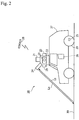
- a data processing device is a device that mainly executes post-processing of measurement data acquired by a mobile mapping system (MMS) 20 illustrated in FIG. 2 .
- MMS mobile mapping system
- the MMS 20 is a measurement system configured as a mobile body equipped with an antenna 21, an IMU 22, a camera 23, a laser scanner 24, a rotary encoder 25, and a synchronization control device 26.
- the mobile body consists of a vehicle 27.
- the antenna 21 is a receiving device to receive a navigation signal from a navigation satellite 28 such as a GNSS satellite. Based on the navigation signal, the antenna 21 acquires satellite positioning data.
- the navigation signal includes, for example, a navigation signal transmission time, trajectory information of the navigation satellite 28, a phase observation value of a carrier wave, and code information to be used for measurement of a navigation signal propagation time, etc.
- the IMU 22 is an inertial measuring device, includes a 3-axis gyroscope and a 3-directional accelerometer, and acquires inertial positioning data.
- the camera 23 is a 360-degree camera consisting of a plurality of cameras, and shoots a video of the entire circumference (2 ⁇ space) including an upper direction.
- video image data shot by the camera is used for construction of three-dimensional information of the surroundings in combination with point group data measured by the laser scanner.
- Exterior orientation elements (positions and postures) of the camera and the laser scanner with respect to the vehicle are measured in advance, and such information is known.
- the laser scanner 24 performs laser scanning of the entire circumference (2 ⁇ space) to acquire point group data of the surrounding environment.
- the laser scanner 24 spirally irradiates a scanning light La, and receives a reflected light Lb from an object such as a road 30 or a building, etc. Based on a time until this reception, by obtaining a three-dimensional position of each reflection point, point group data is acquired.
- the laser scanner 24 is described in, for example, Japanese Published Unexamined Patent Application No. 2008-268004 , etc.
- the rotary encoder 25 is attached to a wheel 29 of the vehicle 27, and acquires vehicle moving distance data from a rotation speed and a rotation angle of the wheel 29.
- the synchronization control device 26 is connected via cables, etc., or wirelessly to the antenna 21, the IMU 22, the camera 23, the laser scanner 24, and the rotary encoder 25.
- the synchronization control device 26 synchronizes a time of inertial positioning data acquisition by the IMU 22, a time of image data acquisition by the camera 23, a time of point group data acquisition by the laser scanner 24, and a time of acquisition of moving distance data of the wheel 29 by the rotary encoder 25.
- the MMS 20 While moving along a route in a measurement section, the MMS 20 acquires satellite positioning data, inertial positioning data, measurement point group data, and moving distance data (hereinafter, these data are collectively referred to as "measurement data") by the antenna 21, the IMU 22, the camera 23, the laser scanner 24, and the rotary encoder 25, respectively.
- measurement data satellite positioning data, inertial positioning data, measurement point group data, and moving distance data
- the data processing device 100 acquires measurement data measured by the MMS 20, and generates three-dimensional point group data of the periphery of the measurement section by using the measurement data.
- the data processing device 100 is a computer.
- the data processing device 100 includes hardware such as a CPU (Central Processing Unit) as a processor, a RAM (Random Access Memory) as a main storage device, a ROM (Read-Only Memory) as an auxiliary storage device, and a HDD (Hard Disk Drive), etc.
- a CPU Central Processing Unit
- RAM Random Access Memory
- ROM Read-Only Memory
- HDD Hard Disk Drive
- the data processing device 100 is configured to be connectable to the antenna 21, the IMU 22, the camera 23, the laser scanner 24, and the rotary encoder 25 via the synchronization control device 26.
- the data processing device 100 may be located outside the vehicle or may be located inside the vehicle. In the present embodiment, for the sake of convenience, the data processing device 100 is assumed to be located outside the vehicle.
- FIG. 3 is a functional block diagram of the data processing device 100.
- the data processing device 100 includes various function units including a data acquiring unit 111, a trajectory calculating unit 112, a virtual level difference detecting unit 113, a trajectory smoothing unit 114, a point group data generating unit 115, a point group matching unit 116, a convergence determining unit 117, and a trajectory adjusting unit 118, and a storage unit 119.
- Each function unit may be configured by software, or may be configured by an exclusive arithmetic circuit.
- function units configured by software and function units configured by exclusive arithmetic circuits may be mixed.
- each of the function units illustrated in the drawings is configured by a CPU (Central Processing Unit), an ASIC (Application Specific Integrated Circuit), and a PLD (Programmable Logic Device) such as an FPGA (Field Programmable Gate Array).
- the data acquiring unit 111 accepts measurement data via an input interface (not illustrated).
- the accepted data is stored in the storage unit 119.
- the input interface is a port to be connected to the synchronization control device 26.
- the input interface is, for example, a USB (Universal Serial Bus) terminal.
- the input interface may be a port to be connected to a LAN (Local Area Network).
- the trajectory calculating unit 112 fuses satellite positioning data acquired by the antenna 21 and inertial positioning data acquired by the IMU 22, or external trajectory data including a trajectory output as a result of point group matching, etc., and inertial positioning data by using a Kalman filter, and calculates a movement trajectory of the vehicle.
- the virtual level difference detecting unit 112 detects whether the trajectory includes a virtual level difference.
- the trajectory smoothing unit 114 executes processing to smooth the virtual level difference in the trajectory.
- the point group data generating unit 115 synthesizes the trajectory data smoothed by the trajectory smoothing unit 114 and measurement point group data at each point acquired by the laser scanner 24 to generate synthetic point group data.
- the point group matching unit 116 executes processing to match the synthetic point group data generated by the point group data generating unit 115 with respect to a forward route and a return route in the same section.
- the convergence determining unit 117 determines whether a virtual level difference exceeding a predetermined threshold is present (whether the virtual level difference has converged) in a trajectory corrected by the point group matching.
- the trajectory adjusting unit 118 adjusts a trajectory on the basis of coordinates of characteristic points (known points that are on the route in the measurement section and are distinguishable from the surroundings such as utility poles, trees, and buildings, etc.).
- the storage unit 119 stores measurement data and data calculated in each function unit.
- the storage unit 119 is realized by a main storage device and an auxiliary storage device, but may be realized only by a main storage device or only by an auxiliary storage device.
- Programs to implement the functions of the respective function units may be stored in a storage medium such as a magnetic disc, a flexible disc, an optical disc, a compact disc, a Blu-ray (registered trademark) disc, a DVD, or the like.
- Step S101 the trajectory calculating unit 112 performs data fusion by using a Kalman filter on the basis of satellite positioning data acquired by the antenna 21 and inertial positioning data acquired by the IMU 22, and calculates a movement trajectory of the vehicle.
- Step S102 the virtual level difference detecting unit 113 detects a virtual level difference in the calculated movement trajectory. Details of the virtual level difference detection processing are described later.
- Step S103 the trajectory smoothing unit 114 performs smoothing of the virtual level difference in the movement trajectory. Details of the smoothing are described later.
- Step S104 the point group data generating unit 115 synthesizes the smoothed vehicle trajectory and measurement point group data acquired by the laser scanner 24 to generate synthetic point group data.
- the synthetic point group data is generated for each of the forward route and return route in the measurement section.
- Step S105 the point group matching unit 116 matches the synthetic point group data of the forward route side and the synthetic point group data of the and return route side.
- Step S106 the convergence determining unit 117 calculates a corrected trajectory from the point group matching results obtained in Step S105, and determines in all virtual level differences detected in Step S102 whether magnitudes D of the virtual level differences are equal to or less than a predetermined threshold Th 1 .
- Step S101 When the magnitudes D of the virtual level differences are not equal to or less than the predetermined threshold Th 1 (No), the processing returns to Step S101, and based on the corrected trajectory and the inertial positioning data acquired by the IMU, the processings of Steps S101 to S106 are repeated until the magnitudes D of the virtual level differences become equal to or less than the predetermined threshold Th 1 .
- Step S107 When the magnitudes D of the virtual level differences are equal to or less than the predetermined threshold Th 1 (Yes), the processing shifts to Step S107, and the point group data generating unit 115 synthesizes the corrected trajectory obtained in Step S106 and the measurement point group data acquired by the laser scanner 24 to generate synthetic point group data.
- Step S108 the trajectory adjusting unit 118 adjusts a trajectory obtained from the synthetic point group data on the basis of the coordinates of the characteristic points.
- Step S109 the trajectory calculating unit 112 performs data fusion by using a Kalman filter on the basis of the trajectory adjusted in Step S108 and the inertial positioning data acquired by the IMU, and re-calculates a trajectory.
- Step S110 virtual level difference detection in the trajectory re-calculated in Step S109 is performed in the same manner as in Step S102.
- Step S111 the trajectory smoothing unit 114 performs smoothing of the trajectory re-calculated in Step S109, in the same manner as in Step S103.
- the smoothing is applied to all virtual level differences detected in Step S110.
- Step S112 the point group data generating unit 115 synthesizes the trajectory smoothed in Step S111 and the measurement point group data acquired by the laser scanner 24 to generate resultant three-dimensional point group data, and the processing ends.
- FIG. 5 is a flowchart of virtual level difference detection processing.
- FIGS. 6A, 6B are diagrams describing a method of detecting a virtual level difference during stoppage of the vehicle, and
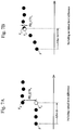
- FIGS. 7A, 7B are diagrams describing a method of detecting a virtual level difference during traveling of the vehicle.
- Step S201 the virtual level difference detecting unit 113 judges whether the vehicle 27 is stopped at each position.
- the judgment as to whether the vehicle 27 is stopped is performed by judging whether a vehicle speed obtained by moving distance data obtained from the rotary encoder 25 is smaller than a predetermined threshold Th 2 .
- Step S201 when the vehicle 27 is judged to be stopped (Yes), the processing shifts to Step S202, and a difference between coordinates of a position P as just after the stoppage of the vehicle and coordinates of a position P bs just before starting to move during stoppage of the vehicle, identified in Step S201, that is, a coordinate difference PD 1 between before and after vehicle stoppage is obtained (refer to FIGS. 6A, 6B ).
- Step S203 whether the coordinate difference PD 1 between before and after the vehicle stoppage obtained in Step S202 is equal to or more than a predetermined threshold Th 3 is judged.
- Step S203 as illustrated in FIG. 6A , when the difference PD 1 between the coordinates of the position P as just after the stoppage of the vehicle and the coordinates of the position P bs just before starting to move is equal to or more than the threshold Th 3 (Yes), the processing shifts to Step S204, and the virtual level difference detecting unit 113 judges that the movement trajectory calculated in Step S101 includes a virtual level difference, and ends the processing.
- Step S203 as illustrated in FIG. 6B , when the difference PD 1 between the coordinates of the position P as just after the stoppage of the vehicle and the coordinates of the position P bs just before starting to move is smaller than the threshold Th 3 (No), the processing shifts to Step S205, and the virtual level difference detecting unit 113 judges that the movement trajectory calculated in Step S101 includes no virtual level difference, and ends the processing.
- Step S201 when it is judged that the vehicle 27 is not stopped at a certain position P (No), the processing shifts to Step S206, and the virtual level difference detecting unit 113 assumes that the vehicle 27 makes uniform motion at that position and predicts coordinates of a position P p of the vehicle 27 a minute time ⁇ t after the time of the position P (refer to FIGS. 7A, 7B ).
- FIGS. 7A and 7B black circles show coordinates of a trajectory calculated based on measurement data, and white circles show coordinates obtained by prediction.
- Step S207 the processing shifts to Step S207, and the predicted coordinates of the position P p of the vehicle 27 after the minute time ⁇ t are compared with coordinates of a position P m of the vehicle 27 after the minute time ⁇ t obtained based on the measurement data, and whether a difference PD 2 between these coordinates is equal to or more than a predetermined threshold Th 4 is judged.
- Step S207 as illustrated in FIG. 7A , when the difference between the predicted coordinates of the position P p of the vehicle 27 after the minute time ⁇ t and the coordinates of the position P m of the vehicle 27 after the minute time ⁇ t obtained based on the measurement data is equal to or more than the threshold Th 4 (Yes), the processing shifts to Step S208, and the virtual level difference detecting unit 113 judges that the movement trajectory calculated in Step S101 includes a virtual level difference, and ends the processing.
- Step S207 as illustrated in FIG. 7B , when the difference PD 2 between the predicted coordinates of the position P p of the vehicle 27 after the minute time ⁇ t and the coordinates of the position P m of the vehicle 27 after the minute time ⁇ t obtained based on the measurement data is smaller than the threshold Th 4 (No), the processing shifts to Step S209, and the virtual level difference detecting unit 113 judges that the movement trajectory calculated in Step S101 includes no virtual level difference D, and ends the processing.
- Steps S202 to S205 are executed for all of the positions at which the vehicle is judged to be stopped in Step S201.
- the processings of Steps S206 to S209 are executed for all of the positions at which the vehicle is judged to be traveling in Step S201.
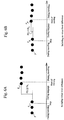
- FIG. 8 is a flowchart of trajectory smoothing.
- FIGS. 9A, 9B are diagrams that schematically represent trajectories before smoothing ( FIG. 9A ) and after smoothing ( FIG. 9B ).
- Step S301 the trajectory smoothing unit 114 calculates a magnitude D of the virtual level difference detected in Step S102.
- Step S302 the trajectory smoothing unit 114 sets a predetermined section before and after the level difference on the trajectory as a processing section S according to the magnitude D of the virtual level difference.
- a processing section S for example, as illustrated in FIG. 9A , a section of ⁇ n ⁇ D before and after the position P D of the virtual level difference is set.
- n is, for example, an arbitrary natural number, and n falls preferably within the range of 8 to 22 because the trajectory is sufficiently smoothed, and more preferably, n falls within the range of 10 to 20.
- Step S203 the range of the processing section S is smoothed, and the processing is ended.
- the trajectory smoothing is performed by, as illustrated in FIG. 9B , a method such as connecting coordinates of a front end P 1 and coordinates of a rear end P 2 of the processing section S with a straight line.
- Step S102 when N virtual level differences are detected in the movement trajectory of the vehicle, the above-described trajectory smoothing is executed for each of the N virtual level differences.
Landscapes
- Engineering & Computer Science (AREA)
- Radar, Positioning & Navigation (AREA)
- Remote Sensing (AREA)
- Automation & Control Theory (AREA)
- Physics & Mathematics (AREA)
- General Physics & Mathematics (AREA)
- Navigation (AREA)
- Image Analysis (AREA)
Applications Claiming Priority (1)
| Application Number | Priority Date | Filing Date | Title |
|---|---|---|---|
| JP2018022750A JP7077044B2 (ja) | 2018-02-13 | 2018-02-13 | データ処理装置、データ処理方法およびデータ処理プログラム |
Publications (1)
| Publication Number | Publication Date |
|---|---|
| EP3524932A1 true EP3524932A1 (en) | 2019-08-14 |
Family
ID=65365907
Family Applications (1)
| Application Number | Title | Priority Date | Filing Date |
|---|---|---|---|
| EP19156294.1A Withdrawn EP3524932A1 (en) | 2018-02-13 | 2019-02-08 | Data processing device, data processing method, and data processing program |
Country Status (3)
| Country | Link |
|---|---|
| US (1) | US11002549B2 (https=) |
| EP (1) | EP3524932A1 (https=) |
| JP (1) | JP7077044B2 (https=) |
Families Citing this family (3)
| Publication number | Priority date | Publication date | Assignee | Title |
|---|---|---|---|---|
| JP7672245B2 (ja) * | 2021-03-08 | 2025-05-07 | 株式会社トプコン | 光学データ処理装置、光学データ処理方法および光学データ処理用プログラム |
| JP7607551B2 (ja) * | 2021-12-24 | 2024-12-27 | 三菱電機株式会社 | 点群生成装置、点群生成方法および点群生成プログラム |
| JP7840256B2 (ja) * | 2022-12-09 | 2026-04-03 | 三菱電機株式会社 | 歪み修正装置、歪み修正方法、および歪み修正プログラム |
Citations (4)
| Publication number | Priority date | Publication date | Assignee | Title |
|---|---|---|---|---|
| JP2008268004A (ja) | 2007-04-20 | 2008-11-06 | Topcon Corp | 多点測定方法及び測量装置 |
| WO2013138183A1 (en) * | 2012-03-12 | 2013-09-19 | Strava, Inc. | Gps data repair |
| JP5494107B2 (ja) * | 2010-03-26 | 2014-05-14 | 三菱電機株式会社 | 車両位置演算装置 |
| JP2017138236A (ja) | 2016-02-04 | 2017-08-10 | 株式会社トプコン | 路面性状の評価方法、及び路面性状の評価装置 |
Family Cites Families (13)
| Publication number | Priority date | Publication date | Assignee | Title |
|---|---|---|---|---|
| JPH01173825A (ja) * | 1987-12-28 | 1989-07-10 | Aisin Aw Co Ltd | 車両用ナビゲーション装置 |
| US6233510B1 (en) * | 1999-10-15 | 2001-05-15 | Meritor Heavy Vehicle Technology, Llc | Method and system for predicting road profile |
| CA2684516C (en) | 2007-04-22 | 2018-02-06 | Ilookabout Inc. | Method of obtaining geographically related images using a vehicle |
| GB2460892B (en) * | 2008-06-17 | 2012-12-19 | Wdm Ltd | Apparatus for measuring carriageway surface properties |
| AU2008358268A1 (en) * | 2008-06-25 | 2009-12-30 | Tomtom International B.V. | Navigation apparatus and method of detection that a parking facility is sought |
| US9533539B2 (en) * | 2011-10-20 | 2017-01-03 | GM Global Technology Operations LLC | Vehicle suspension system and method of using the same |
| JP6274557B2 (ja) | 2013-02-18 | 2018-02-07 | 株式会社リコー | 移動面情報検出装置、及びこれを用いた移動体機器制御システム並びに移動面情報検出用プログラム |
| US9365217B2 (en) * | 2013-06-03 | 2016-06-14 | Booz Allen Hamilton Inc. | Mobile pothole detection system and method |
| US9870437B2 (en) * | 2014-11-24 | 2018-01-16 | Google Llc | Systems and methods for detecting and modeling curb curves in complex urban scenes |
| EP3059129B1 (en) * | 2015-02-17 | 2020-04-15 | Hexagon Technology Center GmbH | Method and system for determining a road condition |
| US10235817B2 (en) * | 2015-09-01 | 2019-03-19 | Ford Global Technologies, Llc | Motion compensation for on-board vehicle sensors |
| US9864368B2 (en) * | 2016-02-08 | 2018-01-09 | Honeywell International Inc. | Methods and apparatus for global optimization of vertical trajectory for an air route |
| JP6406289B2 (ja) | 2016-03-14 | 2018-10-17 | オムロン株式会社 | 路面形状測定装置、測定方法、及び、プログラム |
-
2018
- 2018-02-13 JP JP2018022750A patent/JP7077044B2/ja active Active
-
2019
- 2019-01-16 US US16/249,145 patent/US11002549B2/en active Active
- 2019-02-08 EP EP19156294.1A patent/EP3524932A1/en not_active Withdrawn
Patent Citations (6)
| Publication number | Priority date | Publication date | Assignee | Title |
|---|---|---|---|---|
| JP2008268004A (ja) | 2007-04-20 | 2008-11-06 | Topcon Corp | 多点測定方法及び測量装置 |
| JP5494107B2 (ja) * | 2010-03-26 | 2014-05-14 | 三菱電機株式会社 | 車両位置演算装置 |
| WO2013138183A1 (en) * | 2012-03-12 | 2013-09-19 | Strava, Inc. | Gps data repair |
| EP2825850A1 (en) * | 2012-03-12 | 2015-01-21 | Strava, Inc. | Segment validation |
| EP2825850B1 (en) * | 2012-03-12 | 2019-05-22 | Strava, Inc. | Segment validation |
| JP2017138236A (ja) | 2016-02-04 | 2017-08-10 | 株式会社トプコン | 路面性状の評価方法、及び路面性状の評価装置 |
Also Published As
| Publication number | Publication date |
|---|---|
| US20190249989A1 (en) | 2019-08-15 |
| JP7077044B2 (ja) | 2022-05-30 |
| JP2019138786A (ja) | 2019-08-22 |
| US11002549B2 (en) | 2021-05-11 |
Similar Documents
| Publication | Publication Date | Title |
|---|---|---|
| EP3715783B1 (en) | Point cloud data processing method and point cloud data processing device | |
| CN114636993B (zh) | 一种激光雷达与imu的外参标定方法、装置及设备 | |
| US11443451B2 (en) | Apparatus and method for providing vehicular positioning | |
| JP6865521B2 (ja) | 航法信号処理装置、航法信号処理方法および航法信号処理用プログラム | |
| JP7034379B2 (ja) | 車両測位装置 | |
| CN104136298A (zh) | 测定车辆的速度和/或位置的方法和装置 | |
| JP6330471B2 (ja) | 無線測位装置 | |
| EP3524932A1 (en) | Data processing device, data processing method, and data processing program | |
| US20220113139A1 (en) | Object recognition device, object recognition method and program | |
| KR101764222B1 (ko) | 고정밀 측위 시스템 및 방법 | |
| JP7392839B2 (ja) | 計測装置、計測方法、及びプログラム | |
| JP2025542376A (ja) | レーダー及びモーションセンサを使用したマップ構築のための方法及びシステム | |
| JP4906591B2 (ja) | 位置検知装置 | |
| JP2021143861A (ja) | 情報処理装置、情報処理方法及び情報処理システム | |
| JP7464113B2 (ja) | 位置計測装置、位置計測方法、及びプログラム | |
| JP2023053891A (ja) | 自己位置推定装置及び自己位置推定方法 | |
| JP2002267745A (ja) | センサー統制による同期式追尾方法及び装置 | |
| CN118731998B (zh) | 定位方法、装置、存储介质、电子设备及车辆 | |
| KR20210032694A (ko) | 이미지 기반의 무선 측위 방법 및 장치 | |
| CN118731998A (zh) | 定位方法、装置、存储介质、电子设备及车辆 | |
| JP2012032334A (ja) | Gps測位演算方法及び装置 | |
| JP2025524594A (ja) | 相対測位システムを用いた推測航法システムによる姿勢再調整方法 | |
| CN113607051A (zh) | 一种非暴露空间数字化数据的采集方法、系统及存储介质 | |
| JP2012032331A (ja) | Gps測位演算方法及び装置 | |
| Heidi et al. | Performance Evaluation of Multi-Sensor Fusion Models in Indoor Navigation |
Legal Events
| Date | Code | Title | Description |
|---|---|---|---|
| PUAI | Public reference made under article 153(3) epc to a published international application that has entered the european phase |
Free format text: ORIGINAL CODE: 0009012 |
|
| STAA | Information on the status of an ep patent application or granted ep patent |
Free format text: STATUS: THE APPLICATION HAS BEEN PUBLISHED |
|
| AK | Designated contracting states |
Kind code of ref document: A1 Designated state(s): AL AT BE BG CH CY CZ DE DK EE ES FI FR GB GR HR HU IE IS IT LI LT LU LV MC MK MT NL NO PL PT RO RS SE SI SK SM TR |
|
| AX | Request for extension of the european patent |
Extension state: BA ME |
|
| STAA | Information on the status of an ep patent application or granted ep patent |
Free format text: STATUS: REQUEST FOR EXAMINATION WAS MADE |
|
| 17P | Request for examination filed |
Effective date: 20200213 |
|
| RBV | Designated contracting states (corrected) |
Designated state(s): AL AT BE BG CH CY CZ DE DK EE ES FI FR GB GR HR HU IE IS IT LI LT LU LV MC MK MT NL NO PL PT RO RS SE SI SK SM TR |
|
| STAA | Information on the status of an ep patent application or granted ep patent |
Free format text: STATUS: EXAMINATION IS IN PROGRESS |
|
| 17Q | First examination report despatched |
Effective date: 20220419 |
|
| GRAP | Despatch of communication of intention to grant a patent |
Free format text: ORIGINAL CODE: EPIDOSNIGR1 |
|
| STAA | Information on the status of an ep patent application or granted ep patent |
Free format text: STATUS: GRANT OF PATENT IS INTENDED |
|
| INTG | Intention to grant announced |
Effective date: 20241219 |
|
| STAA | Information on the status of an ep patent application or granted ep patent |
Free format text: STATUS: THE APPLICATION IS DEEMED TO BE WITHDRAWN |
|
| 18D | Application deemed to be withdrawn |
Effective date: 20250423 |