EP3524898B1 - Schalenvorrichtung für wasseraufnahme und klimaanlage - Google Patents
Schalenvorrichtung für wasseraufnahme und klimaanlage Download PDFInfo
- Publication number
- EP3524898B1 EP3524898B1 EP17857807.6A EP17857807A EP3524898B1 EP 3524898 B1 EP3524898 B1 EP 3524898B1 EP 17857807 A EP17857807 A EP 17857807A EP 3524898 B1 EP3524898 B1 EP 3524898B1
- Authority
- EP
- European Patent Office
- Prior art keywords
- receiving tray
- area
- water receiving
- stopper
- groove
- Prior art date
- Legal status (The legal status is an assumption and is not a legal conclusion. Google has not performed a legal analysis and makes no representation as to the accuracy of the status listed.)
- Active
Links
Images
Classifications
-
- F—MECHANICAL ENGINEERING; LIGHTING; HEATING; WEAPONS; BLASTING
- F24—HEATING; RANGES; VENTILATING
- F24F—AIR-CONDITIONING; AIR-HUMIDIFICATION; VENTILATION; USE OF AIR CURRENTS FOR SCREENING
- F24F13/00—Details common to, or for air-conditioning, air-humidification, ventilation or use of air currents for screening
- F24F13/22—Means for preventing condensation or evacuating condensate
- F24F13/222—Means for preventing condensation or evacuating condensate for evacuating condensate
-
- F—MECHANICAL ENGINEERING; LIGHTING; HEATING; WEAPONS; BLASTING
- F24—HEATING; RANGES; VENTILATING
- F24F—AIR-CONDITIONING; AIR-HUMIDIFICATION; VENTILATION; USE OF AIR CURRENTS FOR SCREENING
- F24F13/00—Details common to, or for air-conditioning, air-humidification, ventilation or use of air currents for screening
- F24F13/22—Means for preventing condensation or evacuating condensate
- F24F13/222—Means for preventing condensation or evacuating condensate for evacuating condensate
- F24F2013/225—Means for preventing condensation or evacuating condensate for evacuating condensate by evaporating the condensate in the cooling medium, e.g. in air flow from the condenser
Definitions
- the invention relates to a technical field of heat exchange, and in particular to two alternatives of a water receiving tray assembly and an air conditioner.
- the water receiving tray when a water receiving tray is applied to an air conditioner system, the water receiving tray may be configured to receive condensation water produced in use of an air duct component, and then the condensation water may be drained by the water receiving tray through a drain pipe connected with the water receiving tray.
- the air duct component For the air conditioner system in use, it is necessary for the air duct component to be barrier-free when an air comes in and to prevent air leakage when the air goes out, thus guaranteeing the efficient operation of the air conditioner system.
- an area below the air duct component opposite to the water receiving tray is a high-pressure area; and an area at the drain pipe opposite to the water receiving tray is a low-pressure area.
- the water receiving tray can prevent the air from being blown from the high-pressure area to the low-pressure area while a received condensation water flows through and thus the reduction in the air volume of the air duct component is prevented.
- US 2015/308709 A1 discloses a water receiving tray assembly using valves to reduce gas leakage.
- the invention provides two alternatives for a water receiving tray assembly and an air conditioner, which can prevent air from being blown from a high-pressure area to a low-pressure area when condensation water flows through and thus prevents the reduction in air volume of an air duct component.
- the invention is set out in the appended set of claims.
- An embodiment of the present disclosure provides a water receiving tray assembly, which includes: a water receiving tray body and a first stopper; wherein the water receiving tray body includes a first area for receiving condensation water flowing from an air duct component, a second area communicating with a drain pipe, and a groove located between the first area and the second area; and the first stopper has a first end and a second end, herein the first end is fixed on the water receiving tray body and the second end extends into the groove and is at a predetermined distance from a bottom surface of the groove; when a height of a condensation water in the groove is greater than the predetermined distance, the condensation water in the groove contacts with the first stopper to form a sealed windshield structure.
- a protruded transition portion is formed at a transition position between the second area and the groove, and an upper surface of the transition portion is not higher than a water-out position of the first area and is higher than the second end of the first stopper.
- the first area is provided with an upper surface for flowing through the condensation water; and the upper surface of the first area is provided with a downward predetermined inclination angle along a flowing direction of the condensation water.
- a clamping groove is formed at a position, opposite to the groove, of the water receiving tray body, and the first stopper is fixed on the water receiving tray body by the clamping groove.
- the first stopper and the water receiving tray body are of an integrally moulded structure.
- a barrier layer is disposed on a surface of the second area.
- the water receiving tray assembly further includes a second stopper; the second stopper is located at a transition position between the groove and the second area; and the second stopper is in clearance fit with the water receiving tray body and the barrier layer.
- An air conditioner includes the above-mentioned water receiving tray assembly.
- the first stopper is disposed above the groove between the first area and the second area of the water receiving tray body, and the first stopper can extend into the groove and a predetermined distance is formed between the first stopper and the bottom surface of the groove; and when the height of the condensation water in the groove is greater than the predetermined distance in use, the condensation water in the groove contacts the first stopper to form the sealed windshield structure. Therefore, the water permeable and airtight effect is implemented, and while the condensation water is guaranteed to flow normally, the air is prevented from being blown from the high-pressure area to the low-pressure area and thus the air volume of the air duct component may be guaranteed.
- the embodiments of the present disclosure provide a water receiving tray assembly and an air conditioner capable of preventing air from being blown from a high-pressure area to a low-pressure area while condensation water flows through and thus preventing the reduction of the air volume of an air duct component.
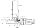
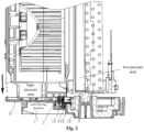
- a water receiving tray assembly provided by the invention will include: a water receiving tray body 1 and a first stopper 2; the water receiving tray body 1 includes a first area 11 for receiving condensation water flowing from an air duct component 3, a second area 12 communicating with a drain pipe, and a groove 13 located between the first area 11 and the second area 12; and the first stopper 2 has a first end and a second end, wherein the first end is fixed on the water receiving tray body 1 and the second end extends into the groove 13 and a predetermined distance is formed between the second end and a bottom surface of the groove 13.
- the condensation water in the groove 13 contacts with the first stopper 2 to form a sealed windshield structure.
- the water receiving tray body 1 is configured to receive the condensation water flowing from the air duct component 3 and guide the condensation water to the drain pipe connected therewith; and the condensation water is drained by the drain pipe.
- the water receiving tray body 1 includes the first area 11 for receiving the condensation water flowing from the air duct component 3, the second area 12 communicating with the drain pipe, and the groove 13 located between the first area 11 and the second area 12, wherein an area where the first area 11 is located is a high-pressure area, and an area where the second area 12 is located is a low-pressure area.
- the first area 11 is located below the outflowed condensation water; and when the condensation water flows downward under an action of gravity, it can be completely flowed into the first area 11 of the water receiving tray body 1.
- the first area 11 is provided with an upper surface for flowing through the condensation water; and the upper surface of the first area is provided with a downward predetermined inclination angle along a flowing direction of the condensation water.
- the predetermined inclination angle is formed on the upper surface of the first area 11 for receiving the condensation water.
- the predetermined inclination angle is formed during mould withdrawal of the water receiving tray body 1 and is the same as a mould withdrawal angle.
- the predetermined inclination angle may further be formed in other machining manners, and is not specifically defined by the present disclosure.
- the predetermined inclination angle may be selected as 2-10° , so that the condensation water can flow downward smoothly.
- the magnitude of the predetermined inclination angle is not limited to the above example and is not specifically defined in the present disclosure.
- an overall surface height of the second area 12 is smaller than a surface height of the first area 11, and the second area 12 communicates with the drain pipe, so that the condensation water flows into the drain pipe for draining.
- the temperature of the condensation water is low.
- the low-temperature condensation water is stopped from directly contacting the surface of the second area 12 and thus the condensation water is prevented from forming on a lower surface of the second area 12.
- the barrier layer 5 is made of foam.
- the material of the barrier layer 5 is not limited to the above example, may further be other material and is not specifically defined in the present disclosure.
- the groove 13 is formed between the first area 11 and the second area 12, the first stopper 2 is disposed on the water receiving tray body 1 above the groove 13, and the first stopper 2 is cooperated with the condensation water in the groove 13 to form the windshield structure that is water permeable and airtight.
- the first stopper 2 is of a structure having one block piece and is provided with a first end and a second end that are opposite, wherein the first end is fixed on the water receiving tray body 1, and the second end extends into the groove 13, and a predetermined distance is formed between the second end and the bottom surface of the groove 13 to preserve a flowing port for the condensation water.
- the first stopper 2 is specifically cooperated with the receiving tray body in a clamping groove fixing manner.
- a clamping groove is formed at a position, opposite to the groove 13, of the water receiving tray body 1, and the first stopper 2 is fixed on the water receiving tray body 1 by the clamping groove.
- the first stopper 2 may be fixed in the clamping groove in a clearance fit manner. At this moment, the first stopper 2 may be made of a rubber with elasticity. Certainly, the material of the first stopper 2 may further be other forms and is not specifically defined in the present disclosure.
- the sealing property between the first stopper 2 and the water receiving tray body 1 in cooperation also can be guaranteed, and the air is prevented from being blown from the high-pressure area to the low-pressure area to affect the air volume of the air duct component 3.
- the first stopper 2 and the water receiving tray body 1 are of an integrally moulded structure.
- the first stopper 2 may be integrally moulded with the water receiving tray body 1.
- the sealing property for the cooperative positions of the first stopper and the receiving tray body can also be guaranteed, and the air is prevented from being blown from the high-pressure area to the low-pressure area to affect the air volume of the air duct component 3.
- a protruded transition portion 14 is formed at a transition position between the second area 12 and the groove 13, and an upper surface of the transition portion 14 is not higher than a water-out position of the first area 11 and is higher than the second end of the first stopper 2.
- the protruded transition portion 14 is formed at the transition position between the second area 12 and the groove 13, and the upper surface of the transition portion 14 may be lower than the water-out position of the first area 11 or is flush with the water-out position of the first area 11.
- the water-out position of the first area 11 may be referred to a position transited with the groove 13.
- the water-out position of the first area 11 is a lowest position of the first area 11.
- the upper surface of the transition portion 14 is higher than the second end of the first stopper 2, so it is ensured that when the condensation water is accumulated in the groove 13, the height of the condensation water can exceed the second end of the first stopper 2 to form a sealed windshield structure with the first stopper.
- the water receiving tray assembly further includes a second stopper 4, the second stopper 4 is located at a transition position between the groove 13 and the second area 12, and the second stopper 4 is in clearance fit with the water receiving tray body 1 and the barrier layer 5.
- the second stopper 4 is disposed at the transition position between the groove 13 and the second area 12, and the second stopper 4 may be in clearance fit with the water receiving tray body 1 and the barrier layer 5.
- the second stopper 4 includes a top surface and a first side surface and a second side surface disposed at two sides of the top surface, wherein the first side surface is abutted against a sidewall, transited with the groove 13, of the second area 12, and the second side surface may be abutted against the barrier layer 5.
- the top surface contacts the transition position between the groove 13 and the second area 12 as well as the barrier layer 5.
- the shape of the second stopper 4 may change correspondingly according to an actual application environment and is not specifically defined in the present disclosure.
- the second stopper 4 When the second stopper 4 is in clearance fit with the water receiving tray body 1 and the barrier layer 5, the second stopper 4 may be made of a rubber with elasticity. Certainly, the material of the second stopper 4 may be in other forms and is not specifically defined in the present disclosure.
- the second stopper 4 When the second stopper 4 is made of the rubber, the second stopper is coated out of the transition position between the groove 13 and the second area 12 as well as the barrier layer 5 in a clearance fit manner, so that the sealing property at the cooperative positions between the second stopper 4, the water receiving tray body 1 and the barrier layer 5 can be guaranteed and the condensation water is prevented from being leaked therefrom.
- the condensation water in the groove 13 contacts the first stopper 2 to form the sealed windshield structure.
- the condensation water can flow into the second area 12 by the flowing port between the first stopper 2 and the groove 13 for draining, and the air cannot be penetrated through under a sealing action of the windshield structure. Therefore, the water receiving tray assembly can automatically form the sealed windshield structure in use to implement the water permeable and airtight effect; and while the condensation water is guaranteed to flow normally, the air is prevented from being blown from the high-pressure area to the low-pressure area, and thus the air volume of the air duct component 3 may be guaranteed.
- the first stopper 2 is disposed above the groove 13 between the first area 11 and the second area 12 of the water receiving tray body 1, and the first stopper 2 can extend into the groove 13 and a predetermined distance is formed between the first stopper 2 and the bottom surface of the groove 13; and when the height of the condensation water in the groove 13 is greater than the predetermined distance in use, the condensation water in the groove 13 contacts the first stopper 2 to form the sealed windshield structure. Therefore, the water permeable and airtight effect is implemented, and while the condensation water is guaranteed to flow normally, the air is prevented from being blown from the high-pressure area to the low-pressure area and thus the air volume of the air duct component 3 may be guaranteed.
- the embodiments of the present disclosure further provide an air conditioner including the water receiving tray assembly in the above-mentioned any embodiment.
- condensation water is produced on an air duct component 3, and the condensation water flows into a first area 11 of a water receiving tray body 1 under an action of gravity and flows into a groove 13 along the first area.
- a sealed windshield structure is formed.
- the condensation water can flow into a second area 12 by a flowing port between the first stopper 2 and the groove 13 for draining, and the air cannot be passed through under the sealing action of the windshield structure.
- the water receiving tray assembly can automatically form the sealed windshield structure in use to implement the water permeable and airtight effect, and while the condensation water is guaranteed to flow normally, the air is prevented from being blown from a high-pressure area to a low-pressure area, and thus the air volume of the air duct component 3 is guaranteed.
- the above-mentioned water receiving tray assembly is not limited to be used in the air conditioner, and may further be used in the fields such as a refrigerator, which is not specifically defined in the present disclosure.
- Each embodiment of the present disclosure is described in a progressive manner, and the same or similar part in each embodiment may be referred to each other.
- the top priority in each embodiment is given to the difference from other embodiments.
Landscapes
- Engineering & Computer Science (AREA)
- Chemical & Material Sciences (AREA)
- Combustion & Propulsion (AREA)
- Mechanical Engineering (AREA)
- General Engineering & Computer Science (AREA)
- Devices For Blowing Cold Air, Devices For Blowing Warm Air, And Means For Preventing Water Condensation In Air Conditioning Units (AREA)
- Air-Conditioning For Vehicles (AREA)
- Removal Of Water From Condensation And Defrosting (AREA)
Claims (9)
- Wasseraufnahmeschalenanordnung, umfassend: einen Wasseraufnahmeschalenkörper (1) und einen ersten Stopfen (2), wobeider Wasseraufnahmewannenkörper (1) einen ersten Bereich (11) zum Aufnehmen von Kondenswasser, das von einer Luftleitungskomponente (3) fließt, einen zweiten Bereich (12), der mit einem Abflussrohr in Verbindung steht, und eine Nut (13), die sich zwischen dem ersten Bereich (11) und dem zweiten Bereich (12) befindet, umfasst und der erste Stopfen (2) ein erstes Ende und ein zweites Ende hat, wobei das erste Ende an dem Wasseraufnahmeschalenkörper (1) befestigt ist und das zweite Ende sich in die Nut (13) erstreckt und in einem vorbestimmten Abstand von einer Bodenfläche der Nut (13) ist; undwenn eine Höhe eines Kondenswassers in der Nut (13) größer als der vorbestimmte Abstand ist, das Kondenswasser in der Nut (13) mit dem ersten Stopfen (2) in Kontakt kommt, um eine abgedichtete Windschutzstruktur zu bilden;wobei eine Klemmnut an einer der Nut (13) gegenüberliegenden Position des Wasseraufnahmeschalenkörpers (1) ausgebildet ist und der erste Stopfen (2) an dem Wasseraufnahmeschalenkörper (1) durch die Klemmnut befestigt ist.
- Wasseraufnahmeschalenanordnung nach Anspruch 1, wobei ein vorstehender Übergangsabschnitt (14) an einer Übergangsposition zwischen dem zweiten Bereich (12) und der Nut (13) ausgebildet ist und eine obere Oberfläche des Übergangsabschnitts (14) nicht höher ist als eine Wasserauslassposition des ersten Bereichs (11) und höher ist als das zweite Ende des ersten Stopfens (2).
- Wasseraufnahmeschalenanordnung nach Anspruch 1, wobei der erste Bereich (11) mit einer oberen Oberfläche zum Durchströmen des Kondenswassers versehen ist und die obere Oberfläche des ersten Bereichs mit einem nach unten gerichteten vorbestimmten Neigungswinkel entlang einer Strömungsrichtung des Kondenswassers versehen ist.
- Wasseraufnahmeschalenanordnung nach Anspruch 1, wobei der erste Stopfen (2) und der Wasseraufnahmeschalenkörper (1) eine einstückig geformte Struktur aufweisen.
- Wasseraufnahmeschalenanordnung nach Anspruch 1, wobei eine Sperrschicht (5) auf einer Oberfläche des zweiten Bereichs (12) angeordnet ist.
- Wasseraufnahmeschalenanordnung nach Anspruch 5, wobei die Wasseraufnahmeschalenanordnung ferner einen zweiten Stopfen (4) umfasst, wobei sich der zweite Stopfen (4) an einer Übergangsposition zwischen der Rille (13) und dem zweiten Bereich befindet und der zweite Stopfen (4) in Spielpassung mit dem Wasseraufnahmeschalenkörper (1) und der Sperrschicht (5) ist.
- Wasseraufnahmeschalenanordnung, umfassend: einen Wasseraufnahmeschalenkörper (1) und einen ersten Stopfen (2), wobeider Wasseraufnahmewannenkörper (1) einen ersten Bereich (11) zum Aufnehmen von Kondenswasser, das von einer Luftleitungskomponente (3) fließt, einen zweiten Bereich (12), der mit einem Abflussrohr in Verbindung steht, und eine Nut (13), die sich zwischen dem ersten Bereich (11) und dem zweiten Bereich (12) befindet, umfasst und der erste Stopfen (2) ein erstes Ende und ein zweites Ende hat, wobei das erste Ende an dem Wasseraufnahmeschalenkörper (1) befestigt ist und das zweite Ende sich in die Nut (13) erstreckt und in einem vorbestimmten Abstand von einer Bodenfläche der Nut (13) ist; undwenn eine Höhe eines Kondenswassers in der Nut (13) größer als der vorbestimmte Abstand ist, das Kondenswasser in der Nut (13) mit dem ersten Stopfen (2) in Kontakt kommt, um eine abgedichtete Windschutzstruktur zu bilden;wobei eine Sperrschicht (5) auf einer Oberfläche des zweiten Bereichs (12) angeordnet ist.
- Wasseraufnahmeschalenanordnung nach Anspruch 7, wobei die Wasseraufnahmeschalenanordnung ferner einen zweiten Stopfen (4) umfasst, wobei sich der zweite Stopfen (4) an einer Übergangsposition zwischen der Rille (13) und dem zweiten Bereich befindet und der zweite Stopfen (4) in Spielpassung mit dem Wasseraufnahmeschalenkörper (1) und der Sperrschicht (5) ist.
- Klimaanlage, die die Wasseraufnahmeschalenanordnung nach einem der Ansprüche 1 bis 8 umfasst.
Applications Claiming Priority (2)
| Application Number | Priority Date | Filing Date | Title |
|---|---|---|---|
| CN201610883049.5A CN106352528B (zh) | 2016-10-08 | 2016-10-08 | 接水盘组件和空调 |
| PCT/CN2017/100689 WO2018064926A1 (zh) | 2016-10-08 | 2017-09-06 | 接水盘组件和空调 |
Publications (3)
| Publication Number | Publication Date |
|---|---|
| EP3524898A1 EP3524898A1 (de) | 2019-08-14 |
| EP3524898A4 EP3524898A4 (de) | 2020-06-10 |
| EP3524898B1 true EP3524898B1 (de) | 2023-04-05 |
Family
ID=57866437
Family Applications (1)
| Application Number | Title | Priority Date | Filing Date |
|---|---|---|---|
| EP17857807.6A Active EP3524898B1 (de) | 2016-10-08 | 2017-09-06 | Schalenvorrichtung für wasseraufnahme und klimaanlage |
Country Status (3)
| Country | Link |
|---|---|
| EP (1) | EP3524898B1 (de) |
| CN (1) | CN106352528B (de) |
| WO (1) | WO2018064926A1 (de) |
Families Citing this family (8)
| Publication number | Priority date | Publication date | Assignee | Title |
|---|---|---|---|---|
| CN106352528B (zh) * | 2016-10-08 | 2021-11-02 | 珠海格力电器股份有限公司 | 接水盘组件和空调 |
| CN110966744B (zh) * | 2018-09-29 | 2024-11-08 | 江苏金新空调有限公司 | 一种方便冷凝水盘安装的薄型风机盘管侧板 |
| CN109708206B (zh) * | 2019-02-25 | 2024-08-23 | 广东美的制冷设备有限公司 | 空调室内机的风道部件和空调室内机 |
| CN109974278B (zh) * | 2019-04-30 | 2024-12-10 | 宁波奥克斯电气股份有限公司 | 一种底盘储水结构及空调器 |
| CN109974276B (zh) * | 2019-04-30 | 2025-02-28 | 宁波奥克斯电气有限公司 | 一种空调器底盘及空调器 |
| CN114576711B (zh) * | 2020-11-30 | 2025-03-18 | 宁波奥克斯电气有限公司 | 空调室内机和空调器 |
| CN115790241B (zh) * | 2022-12-09 | 2026-02-17 | 珠海格力电器股份有限公司 | 一种蒸发器支撑组件、蒸发器组件和空调器 |
| CN115751696B (zh) * | 2022-12-09 | 2024-09-27 | 珠海格力电器股份有限公司 | 接水盘组件、列间空调 |
Family Cites Families (17)
| Publication number | Priority date | Publication date | Assignee | Title |
|---|---|---|---|---|
| JPH07167483A (ja) * | 1993-12-16 | 1995-07-04 | Sanyo Electric Co Ltd | 空気調和機 |
| JP4257843B2 (ja) * | 2003-10-28 | 2009-04-22 | 日東工業株式会社 | キャビネット用冷却装置のドレンパイプの防塵構造 |
| US7854238B2 (en) * | 2007-09-05 | 2010-12-21 | Zatarain Jesus M | Conduit trap and condensation recovery device |
| CN201246863Y (zh) * | 2008-07-22 | 2009-05-27 | 广东美的电器股份有限公司 | 一种空调室内机冷凝水排放装置 |
| KR101091580B1 (ko) * | 2009-08-10 | 2011-12-13 | (주)문명에이스 | 역류방지수단이 구비된 공기조화기의 응축수 배수장치 |
| CN201697300U (zh) * | 2010-06-18 | 2011-01-05 | 广东志高空调有限公司 | 一种挂壁式空调室内机接水盘 |
| JP5382153B2 (ja) * | 2012-02-10 | 2014-01-08 | ダイキン工業株式会社 | 空気調和装置の室内機 |
| GB2508424A (en) * | 2012-11-30 | 2014-06-04 | Greenwood Air Man Ltd | Drain arrangement for gas heat recovery unit |
| JP6092637B2 (ja) * | 2013-01-22 | 2017-03-08 | シャープ株式会社 | 空気調和機の排水構造 |
| JP6349150B2 (ja) * | 2014-05-28 | 2018-06-27 | 日立ジョンソンコントロールズ空調株式会社 | 空気調和機 |
| JP6638166B2 (ja) * | 2015-06-12 | 2020-01-29 | 三菱重工サーマルシステムズ株式会社 | ドレンパン、及び空気調和機 |
| CN105115138B (zh) * | 2015-09-11 | 2018-08-07 | 珠海格力电器股份有限公司 | 一种空调器的冷凝水收集装置及空调器 |
| CN205227734U (zh) * | 2015-11-23 | 2016-05-11 | Tcl空调器(中山)有限公司 | 空调室内机底盘及空调室内机 |
| WO2017141443A1 (ja) * | 2016-02-19 | 2017-08-24 | 三菱電機株式会社 | 熱交換換気装置 |
| CN105757954A (zh) * | 2016-04-20 | 2016-07-13 | 海信(山东)空调有限公司 | 自导水式接水盘及风管机 |
| CN206191855U (zh) * | 2016-10-08 | 2017-05-24 | 珠海格力电器股份有限公司 | 接水盘组件和空调 |
| CN106352528B (zh) * | 2016-10-08 | 2021-11-02 | 珠海格力电器股份有限公司 | 接水盘组件和空调 |
-
2016
- 2016-10-08 CN CN201610883049.5A patent/CN106352528B/zh active Active
-
2017
- 2017-09-06 WO PCT/CN2017/100689 patent/WO2018064926A1/zh not_active Ceased
- 2017-09-06 EP EP17857807.6A patent/EP3524898B1/de active Active
Also Published As
| Publication number | Publication date |
|---|---|
| CN106352528B (zh) | 2021-11-02 |
| EP3524898A1 (de) | 2019-08-14 |
| EP3524898A4 (de) | 2020-06-10 |
| CN106352528A (zh) | 2017-01-25 |
| WO2018064926A1 (zh) | 2018-04-12 |
Similar Documents
| Publication | Publication Date | Title |
|---|---|---|
| EP3524898A1 (de) | Schalenvorrichtung für wasseraufnahme und klimaanlage | |
| US8948580B2 (en) | Foam dam for appliance | |
| US9935301B2 (en) | Pressure equalization element, housing comprising a pressure equalization element, lithium ion accumulator and motor vehicle | |
| US9428043B2 (en) | Liquid vapor separator drain valve | |
| KR102959322B1 (ko) | 통합형 팽창 물탱크, 냉각 시스템 및 자동차 | |
| CN204880445U (zh) | 空调室外机及空调系统 | |
| CN105840893B (zh) | 自动压力排放阀 | |
| US10926608B2 (en) | Refrigerant container | |
| CN104329839B (zh) | 空调系统及其低温启动控制方法 | |
| US20160146094A1 (en) | Safety cap device for controlling pressure in radiator and method for controlling pressure using the same | |
| CN111788375A (zh) | 用于机动车辆的多隔室液体贮存器 | |
| CN106958966B (zh) | 热力膨胀阀 | |
| CN103791663B (zh) | 一种带有单向控制功能的热力膨胀阀 | |
| JP2016091732A (ja) | 燃料電池のエンドプレート | |
| CN103017450A (zh) | 用于冰箱的风道组件及具有它的冰箱 | |
| US11796060B2 (en) | Device for sealing two spaces filled with different fluids in a MEMS sensor system | |
| KR101374936B1 (ko) | 볼밸브 | |
| CN206191855U (zh) | 接水盘组件和空调 | |
| EP2302271A2 (de) | Selbstdichtendes Abflussanschlussstück | |
| US9822880B2 (en) | Watertight seal design for vehicle evaporator tubes and valve | |
| CN203032333U (zh) | 车辆用空调装置的配管部收容构造 | |
| CN216009685U (zh) | 简易式溢流阀 | |
| CN104235493B (zh) | 膨胀阀及其制造方法 | |
| CN215244242U (zh) | 车辆的管路固定装置及车辆 | |
| KR20250156088A (ko) | 전기화학 및 전기기술 부품용 냉각 장치 |
Legal Events
| Date | Code | Title | Description |
|---|---|---|---|
| STAA | Information on the status of an ep patent application or granted ep patent |
Free format text: STATUS: THE INTERNATIONAL PUBLICATION HAS BEEN MADE |
|
| PUAI | Public reference made under article 153(3) epc to a published international application that has entered the european phase |
Free format text: ORIGINAL CODE: 0009012 |
|
| STAA | Information on the status of an ep patent application or granted ep patent |
Free format text: STATUS: REQUEST FOR EXAMINATION WAS MADE |
|
| 17P | Request for examination filed |
Effective date: 20190508 |
|
| AK | Designated contracting states |
Kind code of ref document: A1 Designated state(s): AL AT BE BG CH CY CZ DE DK EE ES FI FR GB GR HR HU IE IS IT LI LT LU LV MC MK MT NL NO PL PT RO RS SE SI SK SM TR |
|
| AX | Request for extension of the european patent |
Extension state: BA ME |
|
| DAV | Request for validation of the european patent (deleted) | ||
| DAX | Request for extension of the european patent (deleted) | ||
| A4 | Supplementary search report drawn up and despatched |
Effective date: 20200513 |
|
| RIC1 | Information provided on ipc code assigned before grant |
Ipc: F24F 13/22 20060101AFI20200507BHEP |
|
| GRAP | Despatch of communication of intention to grant a patent |
Free format text: ORIGINAL CODE: EPIDOSNIGR1 |
|
| STAA | Information on the status of an ep patent application or granted ep patent |
Free format text: STATUS: GRANT OF PATENT IS INTENDED |
|
| INTG | Intention to grant announced |
Effective date: 20221024 |
|
| GRAS | Grant fee paid |
Free format text: ORIGINAL CODE: EPIDOSNIGR3 |
|
| GRAA | (expected) grant |
Free format text: ORIGINAL CODE: 0009210 |
|
| STAA | Information on the status of an ep patent application or granted ep patent |
Free format text: STATUS: THE PATENT HAS BEEN GRANTED |
|
| AK | Designated contracting states |
Kind code of ref document: B1 Designated state(s): AL AT BE BG CH CY CZ DE DK EE ES FI FR GB GR HR HU IE IS IT LI LT LU LV MC MK MT NL NO PL PT RO RS SE SI SK SM TR |
|
| REG | Reference to a national code |
Ref country code: GB Ref legal event code: FG4D |
|
| REG | Reference to a national code |
Ref country code: CH Ref legal event code: EP |
|
| REG | Reference to a national code |
Ref country code: AT Ref legal event code: REF Ref document number: 1558504 Country of ref document: AT Kind code of ref document: T Effective date: 20230415 |
|
| REG | Reference to a national code |
Ref country code: DE Ref legal event code: R096 Ref document number: 602017067538 Country of ref document: DE |
|
| REG | Reference to a national code |
Ref country code: IE Ref legal event code: FG4D |
|
| P01 | Opt-out of the competence of the unified patent court (upc) registered |
Effective date: 20230530 |
|
| REG | Reference to a national code |
Ref country code: LT Ref legal event code: MG9D |
|
| REG | Reference to a national code |
Ref country code: NL Ref legal event code: MP Effective date: 20230405 |
|
| REG | Reference to a national code |
Ref country code: AT Ref legal event code: MK05 Ref document number: 1558504 Country of ref document: AT Kind code of ref document: T Effective date: 20230405 |
|
| PG25 | Lapsed in a contracting state [announced via postgrant information from national office to epo] |
Ref country code: NL Free format text: LAPSE BECAUSE OF FAILURE TO SUBMIT A TRANSLATION OF THE DESCRIPTION OR TO PAY THE FEE WITHIN THE PRESCRIBED TIME-LIMIT Effective date: 20230405 |
|
| PG25 | Lapsed in a contracting state [announced via postgrant information from national office to epo] |
Ref country code: SE Free format text: LAPSE BECAUSE OF FAILURE TO SUBMIT A TRANSLATION OF THE DESCRIPTION OR TO PAY THE FEE WITHIN THE PRESCRIBED TIME-LIMIT Effective date: 20230405 Ref country code: PT Free format text: LAPSE BECAUSE OF FAILURE TO SUBMIT A TRANSLATION OF THE DESCRIPTION OR TO PAY THE FEE WITHIN THE PRESCRIBED TIME-LIMIT Effective date: 20230807 Ref country code: NO Free format text: LAPSE BECAUSE OF FAILURE TO SUBMIT A TRANSLATION OF THE DESCRIPTION OR TO PAY THE FEE WITHIN THE PRESCRIBED TIME-LIMIT Effective date: 20230705 Ref country code: ES Free format text: LAPSE BECAUSE OF FAILURE TO SUBMIT A TRANSLATION OF THE DESCRIPTION OR TO PAY THE FEE WITHIN THE PRESCRIBED TIME-LIMIT Effective date: 20230405 Ref country code: AT Free format text: LAPSE BECAUSE OF FAILURE TO SUBMIT A TRANSLATION OF THE DESCRIPTION OR TO PAY THE FEE WITHIN THE PRESCRIBED TIME-LIMIT Effective date: 20230405 |
|
| PG25 | Lapsed in a contracting state [announced via postgrant information from national office to epo] |
Ref country code: RS Free format text: LAPSE BECAUSE OF FAILURE TO SUBMIT A TRANSLATION OF THE DESCRIPTION OR TO PAY THE FEE WITHIN THE PRESCRIBED TIME-LIMIT Effective date: 20230405 Ref country code: PL Free format text: LAPSE BECAUSE OF FAILURE TO SUBMIT A TRANSLATION OF THE DESCRIPTION OR TO PAY THE FEE WITHIN THE PRESCRIBED TIME-LIMIT Effective date: 20230405 Ref country code: LV Free format text: LAPSE BECAUSE OF FAILURE TO SUBMIT A TRANSLATION OF THE DESCRIPTION OR TO PAY THE FEE WITHIN THE PRESCRIBED TIME-LIMIT Effective date: 20230405 Ref country code: LT Free format text: LAPSE BECAUSE OF FAILURE TO SUBMIT A TRANSLATION OF THE DESCRIPTION OR TO PAY THE FEE WITHIN THE PRESCRIBED TIME-LIMIT Effective date: 20230405 Ref country code: IS Free format text: LAPSE BECAUSE OF FAILURE TO SUBMIT A TRANSLATION OF THE DESCRIPTION OR TO PAY THE FEE WITHIN THE PRESCRIBED TIME-LIMIT Effective date: 20230805 Ref country code: HR Free format text: LAPSE BECAUSE OF FAILURE TO SUBMIT A TRANSLATION OF THE DESCRIPTION OR TO PAY THE FEE WITHIN THE PRESCRIBED TIME-LIMIT Effective date: 20230405 Ref country code: GR Free format text: LAPSE BECAUSE OF FAILURE TO SUBMIT A TRANSLATION OF THE DESCRIPTION OR TO PAY THE FEE WITHIN THE PRESCRIBED TIME-LIMIT Effective date: 20230706 Ref country code: AL Free format text: LAPSE BECAUSE OF FAILURE TO SUBMIT A TRANSLATION OF THE DESCRIPTION OR TO PAY THE FEE WITHIN THE PRESCRIBED TIME-LIMIT Effective date: 20230405 |
|
| PG25 | Lapsed in a contracting state [announced via postgrant information from national office to epo] |
Ref country code: FI Free format text: LAPSE BECAUSE OF FAILURE TO SUBMIT A TRANSLATION OF THE DESCRIPTION OR TO PAY THE FEE WITHIN THE PRESCRIBED TIME-LIMIT Effective date: 20230405 |
|
| REG | Reference to a national code |
Ref country code: DE Ref legal event code: R097 Ref document number: 602017067538 Country of ref document: DE |
|
| PG25 | Lapsed in a contracting state [announced via postgrant information from national office to epo] |
Ref country code: SK Free format text: LAPSE BECAUSE OF FAILURE TO SUBMIT A TRANSLATION OF THE DESCRIPTION OR TO PAY THE FEE WITHIN THE PRESCRIBED TIME-LIMIT Effective date: 20230405 |
|
| PG25 | Lapsed in a contracting state [announced via postgrant information from national office to epo] |
Ref country code: SM Free format text: LAPSE BECAUSE OF FAILURE TO SUBMIT A TRANSLATION OF THE DESCRIPTION OR TO PAY THE FEE WITHIN THE PRESCRIBED TIME-LIMIT Effective date: 20230405 Ref country code: SK Free format text: LAPSE BECAUSE OF FAILURE TO SUBMIT A TRANSLATION OF THE DESCRIPTION OR TO PAY THE FEE WITHIN THE PRESCRIBED TIME-LIMIT Effective date: 20230405 Ref country code: RO Free format text: LAPSE BECAUSE OF FAILURE TO SUBMIT A TRANSLATION OF THE DESCRIPTION OR TO PAY THE FEE WITHIN THE PRESCRIBED TIME-LIMIT Effective date: 20230405 Ref country code: EE Free format text: LAPSE BECAUSE OF FAILURE TO SUBMIT A TRANSLATION OF THE DESCRIPTION OR TO PAY THE FEE WITHIN THE PRESCRIBED TIME-LIMIT Effective date: 20230405 Ref country code: DK Free format text: LAPSE BECAUSE OF FAILURE TO SUBMIT A TRANSLATION OF THE DESCRIPTION OR TO PAY THE FEE WITHIN THE PRESCRIBED TIME-LIMIT Effective date: 20230405 Ref country code: CZ Free format text: LAPSE BECAUSE OF FAILURE TO SUBMIT A TRANSLATION OF THE DESCRIPTION OR TO PAY THE FEE WITHIN THE PRESCRIBED TIME-LIMIT Effective date: 20230405 |
|
| PLBE | No opposition filed within time limit |
Free format text: ORIGINAL CODE: 0009261 |
|
| STAA | Information on the status of an ep patent application or granted ep patent |
Free format text: STATUS: NO OPPOSITION FILED WITHIN TIME LIMIT |
|
| 26N | No opposition filed |
Effective date: 20240108 |
|
| REG | Reference to a national code |
Ref country code: CH Ref legal event code: PL |
|
| PG25 | Lapsed in a contracting state [announced via postgrant information from national office to epo] |
Ref country code: SI Free format text: LAPSE BECAUSE OF FAILURE TO SUBMIT A TRANSLATION OF THE DESCRIPTION OR TO PAY THE FEE WITHIN THE PRESCRIBED TIME-LIMIT Effective date: 20230405 |
|
| PG25 | Lapsed in a contracting state [announced via postgrant information from national office to epo] |
Ref country code: LU Free format text: LAPSE BECAUSE OF NON-PAYMENT OF DUE FEES Effective date: 20230906 |
|
| REG | Reference to a national code |
Ref country code: BE Ref legal event code: MM Effective date: 20230930 |
|
| GBPC | Gb: european patent ceased through non-payment of renewal fee |
Effective date: 20230906 |
|
| PG25 | Lapsed in a contracting state [announced via postgrant information from national office to epo] |
Ref country code: SI Free format text: LAPSE BECAUSE OF FAILURE TO SUBMIT A TRANSLATION OF THE DESCRIPTION OR TO PAY THE FEE WITHIN THE PRESCRIBED TIME-LIMIT Effective date: 20230405 Ref country code: LU Free format text: LAPSE BECAUSE OF NON-PAYMENT OF DUE FEES Effective date: 20230906 Ref country code: IT Free format text: LAPSE BECAUSE OF FAILURE TO SUBMIT A TRANSLATION OF THE DESCRIPTION OR TO PAY THE FEE WITHIN THE PRESCRIBED TIME-LIMIT Effective date: 20230405 Ref country code: MC Free format text: LAPSE BECAUSE OF FAILURE TO SUBMIT A TRANSLATION OF THE DESCRIPTION OR TO PAY THE FEE WITHIN THE PRESCRIBED TIME-LIMIT Effective date: 20230405 |
|
| REG | Reference to a national code |
Ref country code: IE Ref legal event code: MM4A |
|
| PG25 | Lapsed in a contracting state [announced via postgrant information from national office to epo] |
Ref country code: IE Free format text: LAPSE BECAUSE OF NON-PAYMENT OF DUE FEES Effective date: 20230906 |
|
| PG25 | Lapsed in a contracting state [announced via postgrant information from national office to epo] |
Ref country code: GB Free format text: LAPSE BECAUSE OF NON-PAYMENT OF DUE FEES Effective date: 20230906 |
|
| PG25 | Lapsed in a contracting state [announced via postgrant information from national office to epo] |
Ref country code: CH Free format text: LAPSE BECAUSE OF NON-PAYMENT OF DUE FEES Effective date: 20230930 |
|
| PG25 | Lapsed in a contracting state [announced via postgrant information from national office to epo] |
Ref country code: IE Free format text: LAPSE BECAUSE OF NON-PAYMENT OF DUE FEES Effective date: 20230906 Ref country code: GB Free format text: LAPSE BECAUSE OF NON-PAYMENT OF DUE FEES Effective date: 20230906 Ref country code: FR Free format text: LAPSE BECAUSE OF NON-PAYMENT OF DUE FEES Effective date: 20230930 Ref country code: CH Free format text: LAPSE BECAUSE OF NON-PAYMENT OF DUE FEES Effective date: 20230930 |
|
| PG25 | Lapsed in a contracting state [announced via postgrant information from national office to epo] |
Ref country code: BE Free format text: LAPSE BECAUSE OF NON-PAYMENT OF DUE FEES Effective date: 20230930 |
|
| PG25 | Lapsed in a contracting state [announced via postgrant information from national office to epo] |
Ref country code: BG Free format text: LAPSE BECAUSE OF FAILURE TO SUBMIT A TRANSLATION OF THE DESCRIPTION OR TO PAY THE FEE WITHIN THE PRESCRIBED TIME-LIMIT Effective date: 20230405 |
|
| PG25 | Lapsed in a contracting state [announced via postgrant information from national office to epo] |
Ref country code: BG Free format text: LAPSE BECAUSE OF FAILURE TO SUBMIT A TRANSLATION OF THE DESCRIPTION OR TO PAY THE FEE WITHIN THE PRESCRIBED TIME-LIMIT Effective date: 20230405 |
|
| PG25 | Lapsed in a contracting state [announced via postgrant information from national office to epo] |
Ref country code: CY Free format text: LAPSE BECAUSE OF FAILURE TO SUBMIT A TRANSLATION OF THE DESCRIPTION OR TO PAY THE FEE WITHIN THE PRESCRIBED TIME-LIMIT; INVALID AB INITIO Effective date: 20170906 |
|
| PG25 | Lapsed in a contracting state [announced via postgrant information from national office to epo] |
Ref country code: HU Free format text: LAPSE BECAUSE OF FAILURE TO SUBMIT A TRANSLATION OF THE DESCRIPTION OR TO PAY THE FEE WITHIN THE PRESCRIBED TIME-LIMIT; INVALID AB INITIO Effective date: 20170906 |
|
| PGFP | Annual fee paid to national office [announced via postgrant information from national office to epo] |
Ref country code: DE Payment date: 20250919 Year of fee payment: 9 |
|
| PG25 | Lapsed in a contracting state [announced via postgrant information from national office to epo] |
Ref country code: TR Free format text: LAPSE BECAUSE OF FAILURE TO SUBMIT A TRANSLATION OF THE DESCRIPTION OR TO PAY THE FEE WITHIN THE PRESCRIBED TIME-LIMIT Effective date: 20230405 |