EP3524738A1 - Behältnis zum abgedichteten einbau in eine wand - Google Patents
Behältnis zum abgedichteten einbau in eine wand Download PDFInfo
- Publication number
- EP3524738A1 EP3524738A1 EP18155915.4A EP18155915A EP3524738A1 EP 3524738 A1 EP3524738 A1 EP 3524738A1 EP 18155915 A EP18155915 A EP 18155915A EP 3524738 A1 EP3524738 A1 EP 3524738A1
- Authority
- EP
- European Patent Office
- Prior art keywords
- frame
- wall
- container
- box
- container according
- Prior art date
- Legal status (The legal status is an assumption and is not a legal conclusion. Google has not performed a legal analysis and makes no representation as to the accuracy of the status listed.)
- Granted
Links
Images

Classifications
-
- E—FIXED CONSTRUCTIONS
- E03—WATER SUPPLY; SEWERAGE
- E03D—WATER-CLOSETS OR URINALS WITH FLUSHING DEVICES; FLUSHING VALVES THEREFOR
- E03D1/00—Water flushing devices with cisterns ; Setting up a range of flushing devices or water-closets; Combinations of several flushing devices
- E03D1/01—Shape or selection of material for flushing cisterns
- E03D1/012—Details of shape of cisterns, e.g. for connecting to wall, for supporting or connecting flushing-device actuators
- E03D1/0125—Details of shape of cisterns, e.g. for connecting to wall, for supporting or connecting flushing-device actuators of built-in cisterns
-
- E—FIXED CONSTRUCTIONS
- E03—WATER SUPPLY; SEWERAGE
- E03B—INSTALLATIONS OR METHODS FOR OBTAINING, COLLECTING, OR DISTRIBUTING WATER
- E03B7/00—Water main or service pipe systems
- E03B7/09—Component parts or accessories
- E03B7/095—Component holders or housings, e.g. boundary boxes
-
- E—FIXED CONSTRUCTIONS
- E03—WATER SUPPLY; SEWERAGE
- E03C—DOMESTIC PLUMBING INSTALLATIONS FOR FRESH WATER OR WASTE WATER; SINKS
- E03C1/00—Domestic plumbing installations for fresh water or waste water; Sinks
- E03C1/02—Plumbing installations for fresh water
- E03C1/021—Devices for positioning or connecting of water supply lines
-
- H—ELECTRICITY
- H02—GENERATION; CONVERSION OR DISTRIBUTION OF ELECTRIC POWER
- H02G—INSTALLATION OF ELECTRIC CABLES OR LINES, OR OF COMBINED OPTICAL AND ELECTRIC CABLES OR LINES
- H02G3/00—Installations of electric cables or lines or protective tubing therefor in or on buildings, equivalent structures or vehicles
- H02G3/02—Details
- H02G3/08—Distribution boxes; Connection or junction boxes
- H02G3/088—Dustproof, splashproof, drip-proof, waterproof, or flameproof casings or inlets
-
- H—ELECTRICITY
- H02—GENERATION; CONVERSION OR DISTRIBUTION OF ELECTRIC POWER
- H02G—INSTALLATION OF ELECTRIC CABLES OR LINES, OR OF COMBINED OPTICAL AND ELECTRIC CABLES OR LINES
- H02G3/00—Installations of electric cables or lines or protective tubing therefor in or on buildings, equivalent structures or vehicles
- H02G3/02—Details
- H02G3/08—Distribution boxes; Connection or junction boxes
- H02G3/12—Distribution boxes; Connection or junction boxes for flush mounting
Definitions
- the present invention relates to a container, which in a wall, for. B. a bathroom wall to be installed sealed.
- the container is generally meant in the context of this presentation and can, for. B. serve as a shelf or record a tray. For the case of a bathroom wall mentioned above, this could be toiletries, cosmetics, towels, etc. It can also be z. As a container for receiving a concealed cistern, a toilet or other water dispenser, z. B. a purge valve act. In particular, the container can form a leakage protection for the water dispenser.
- WCs have a water rinse and the most common solution involves a cistern for storing a sufficient volume of rinse water.
- Modern cisterns usually consist essentially of an injection molded or blow molded plastic tank and in the past, ceramic cisterns were in use. Regardless of the choice of material cistern always has a certain residual risk of leakage. For example. For example, a small damage to the cistern may occur on the construction site or during the assembly process and remain undetected, which would result in concealed water leakage, especially when flush-mounted cisterns are no longer visible after installation in a room wall.
- the container according to the invention instead of receiving a water dispenser but as I said also z. B. in the manner of a piece of furniture for storage of various user-side on and clear objects, z. B. in a shower area of a bathroom. It may have to trays, such as shelves. Even such containers for sealed wall installation are known per se.
- the container may also be part of a water outlet, in particular in a bathroom, wall drains and floor drains being considered.
- wall also applies to a floor or a ceiling, with a vertical wall (in contrast to the floor and to the ceiling) being preferred.
- a container for receiving the draining water which is also installed in a manner sealed to the wall.
- the invention has for its object to develop such a container in terms of its practical properties.
- a container for sealed installation in a wall which container comprises: with respect to a built-in position to the front open or open and closed to the rear and the other sides closed box, and a peripheral opening at the front frame characterized in that the frame is connected to the box via a connecting wall which is compliant relative to a direction of movement perpendicular to the opening and can be mounted offset from the opening in the direction perpendicular to the opening to varying degrees, and a use of the box for installation in a wall.
- the container according to the invention has at least three basic elements, namely a box, a frame and a "connecting" wall connecting them.
- the box has an opening, the corresponding side of the box being referred to herein as the front. This is the accessible after installation in the wall side, which is preferably substantially parallel to the wall plane and also preferably can be installed flush with the wall.
- the box is closed, namely on the opposite side, ie to the rear, and on the other sides, so right, left, up and down, where it does not depend on the distinction between them at this point.
- the box is so unilaterally open and should be installed so that this opening is accessible.
- the box consists of a sufficiently dimensionally stable material for the applications described below.
- the box should be at least as dimensionally stable that it retains its own box shape without further action.
- a stiffer material is preferred, such as a plastic with a sufficient wall thickness or sheet metal.
- the frame should be provided in a manner surrounding the opening of the box, but is not provided directly to the opening, but slightly offset from this and connected by said wall with the box.
- the term "circumferential" thus means that the opening is accessible through the frame.
- the frame extends in a projection (preferably perpendicular to a plane defined by the opening) substantially around the edge of the opening.
- the frame should be provided after installation on the wall in which the container is installed, preferably, but not necessarily flush. In particular, the frame can project something into the space in front of the wall.
- the frame should be designed dimensionally stable, which he is particularly suitable for mounting on the z. B. bathroom wall and in particular during installation can also be used as a facility or to define a reference plane.
- Dimensionally stable means that the frame its z. B. rectangular shape even when acted upon by z. B. usual physical forces of a craftsman during assembly maintains. So he can z. B. of a dimensionally stable plastic material, such as an injection molded part, or made of sheet metal.
- the frame is preferably closed, so has no gap, and further preferably rectangular with possibly slightly rounded corners. In a sectional plane perpendicular to the wall or opening, it can have a flat profile with a longer extent perpendicular to the wall and opening than parallel thereto.
- the connecting wall (connecting the frame and the box) provides a tight connection therebetween so that, since the box is also sealed, the entire container is ultimately substantially leak-tight in the installed condition with respect to passage of moisture.
- the box or other elements of the container prior to installation may have mounting holes, such as holes for screws, which are then sealed tightly during assembly.
- the connecting wall should be compliant with respect to the direction perpendicular to the opening, so that the distance between the frame and the box is variable. This direction is only to be understood as an approximate indication because the opening does not necessarily have to define a plane precisely. But it is about being able to adjust the distance during installation and thus z. B. to different installation conditions, such as different wall thicknesses, wall panel thicknesses, positions of mounting options and others to be able to respond.
- the connecting wall is preferably made of a flexible material, ie a variable material with respect to its shape such.
- a flexible material ie a variable material with respect to its shape such.
- a film, a dense fabric or other textile, or a combination such as a film-coated fabric, a non-woven coated film or fabric-reinforced
- This is not mandatory, but it could be at the connecting wall also a balgähnliche and in other directions not necessarily yielding solution.
- the flexibility provides adaptability combined with a frame that is dimensionally stable.
- the container according to the invention preferably also has such a seal.
- This can be designed to protrude from the frame in the wall plane and thus preferably substantially in the plane of the front opening of the box to the outside. Either the seal has this position prior to assembly or it is brought by attaching to the frame in this position or it is attached to the frame before mounting, but directed inward and can then during assembly by folding outward in that position to be brought.
- the seal is preferably flexible and consists for. B. from a film, such as a non-woven film.
- the seal can already in the production, for. B. from the outside, attached to the frame, z. B. glued, be.
- “outside” refers to one side of the frame, which is opposite to the side facing inwardly with respect to the opening defined by the frame. It can also be attached to the front frame edge, such as by spraying.
- a further preferred embodiment provides additional, relative to the seal rigid strips on the frame, which protrude at least in the mounted position of this outward.
- These strips can be repositioned and accordingly previously z. B. have stood away inside and are only folded during assembly to the outside. This can be z. B. take place in that they are applied to the aforementioned seal, z. B. by sticking. They serve to provide a flexible seal evenly and over the largest possible Press part of their frame circumferential length, glue or otherwise attach in the final sealing position on the wall can.
- the strips preferably each capture at least 80%, preferably at least 90% or 95%, of the length of a rectangular edge of the frame, cf. the embodiment.
- the seal is provided separately and not as an integrated part of the container according to the invention and attached, such strips can be helpful. Accordingly, in the unassembled state of the container, they can be present as separate loose parts, in order to then be attached, for instance glued on. Incidentally, the strips can form a peripheral flange as a special case, which surrounds the frame, rests on the front of the seal and thus ensures a circumferential good investment of a seal on the wall. Then the aforementioned folding away and the flange is either already attached to the frame in the unassembled state or set up as a separate part.
- the distance between the frame and the box can advantageously be adjusted by means of an adjustment device which accordingly acts perpendicular to the wall plane or opening at the front of the box (as always meant only approximately).
- an adjustment device which accordingly acts perpendicular to the wall plane or opening at the front of the box (as always meant only approximately).
- at least one threaded rod with a mating thread can be used.
- the fitter can thus set the exact distance and also specify, for. B. after installation of the box and with respect to a specific position of the frame relative to the front wall (flush or with a defined projection).
- a further preferred embodiment provides a pre-embossed fold in the flexible material wall between the frame and the box.
- the fold may be pre-stamped by ironing.
- the assembled container and in particular the box therein can be coated on the inside according to the other wall after installation or otherwise.
- a tile covering the (sanitary) wall can also be drawn into the container.
- the container could be tiled or otherwise coated deviating from the rest of the wall surface.
- a preferred use is in addition to the leakage protection for various water dispensers especially in a storage box.
- the z. B. inside verflieste container itself and absorb shampoo bottles and other hygiene or personal care items, cosmetics, laundry or the like.
- an additional shelf can be installed or even a separate furniture like insert inserted into the container.
- the figures show a molded or deep-drawn from a rigid plastic or welded from sheet metal or deep-drawn box 1 with a particular in Fig. 3 visible square base and four of which projecting forward and interconnected walls. In the corners between these walls are in Fig. 4 and in Fig. 1 and 2 (there in section) highly visible pipe pieces 2 attached (or integrated in the injection molding), which have an internal thread and into which a respective threaded rod 3 engages. A head of each threaded rod 3 is held in an eyelet of a likewise square frame 4, which according to the Fig. 1 and 2 has a flat profile with a longer profile direction perpendicular to the wall and in the rest as a closed frame, the outer contour of the square outline of the box 1 resumes.
- the frame 4 is an injection-molded plastic part, to which in its manufacture a film seal 5 which is clearly visible in the figures is attached to the (in the Fig. 1 and 2 pointing to the left) front edge of the frame 4 is molded.
- the film seal 5 is therefore flat overall and does not have to be deep-drawn. Alternatively, it could be deep-drawn adapted to a small distance to the outer edge of the frame and then glued to the frame from the outside, such as when it should be made of sheet metal.
- the film seal 5 consists of a bleached plastic film with a certain elasticity, with which it can be glued well and without wrinkles and bubbles on a bathroom wall.
- the relative to the film seal 5 and the connecting wall 7 relatively rigid frame 4 facilitates the fitter the work because he specifies a defined reference geometry and in particular reference edges. It also promotes a clean and geometrically true course of the film seal 5. Also, it can form a stop edge for laying tiles or plates or plastering with appropriate design.
- the invention allows a certain variability of the distance between the frame 4 and the box 1 in a direction perpendicular to the wall and thus also to the front opening in the box 1 direction, ie in the Fig. 1 and 2 horizontal and in Fig. 3 perpendicular to the drawing plane.
- a connecting wall 7 is provided, which in Fig. 1 and 4 folded and maximally merged and in Fig. 2 and 5 stretched largely wrinkle-free tight. Accordingly, the mentioned distance changes.
- the connecting wall is made of a dense plastic film material, which may or may not be stretchable, and in a similar manner as the film seal 5 may be molded on the frame 4 and / or the side walls of the box 1 or adhered externally or internally.
- the film material may additionally z. B. pre-stamped by ironing Get wrinkles, in which it is in the in the Fig. 1 and 4 state shown.
- the connecting wall 7 is accordingly guarantor for a tight connection between the frame 4 and the box 1 with simultaneous adjustability of the distance between them.
- the threaded rods 3 are accordingly adjustable by turning relative to the pipe sections 2 and thus relative to the box 1. By appropriate adjustment, they either give a maximum forward position of the frame 4, namely when it is held on the threaded rods 3 and blocked by their heads forward, or even define its position, namely when the heads or other parts of the threaded rods rotatable but not axially displaceable are coupled to the frame 4.
- the fitter z. B. first the box 1 z. B. on a well-known from the prior art mounting frame (as it is known about for mounting washbasin, hanging toilets and the like) attach. These can z. B. are guided from the inside through the side walls of the box 1 in a sealed manner screws or the box 1 z. B. with outer strips 6 or grooves positively inserted into corresponding mounting structures on the mounting frame (or other device of the wall) or otherwise positively secured.
- the fitter can adjust the frame 4 by means of the threaded rods 3 to a desired position and thus z.
- the wall covering so as the tiles or natural stone slabs, not only be applied to the wall from the outside, but also in the Container in and thus around the front edge of the frame 4 around.
- the connecting wall in the direction perpendicular to the (bathroom) wall interfere with the flexibility and possibly elasticity of the connecting wall, but it can be bridged.
- the container can also be lined elsewhere and the frame 4 with respect to the foil seal 5 can survive a bit forward and in the installed and finished state as flush contact edge for z. As tiles are visible.
- shelf-like storage boards or even insert them in the waterproof built-in container eg a less than wall component, but also a piece of furniture designed as a box-shaped element
- the container could also serve for leak-proof placement of valves, cisterns or similar elements, which can be combined with the function of storage or storage box.
Landscapes
- Health & Medical Sciences (AREA)
- Life Sciences & Earth Sciences (AREA)
- Engineering & Computer Science (AREA)
- Hydrology & Water Resources (AREA)
- Public Health (AREA)
- Water Supply & Treatment (AREA)
- Bathtubs, Showers, And Their Attachments (AREA)
Abstract
Description
- Die vorliegende Erfindung bezieht sich auf ein Behältnis, das in eine Wand, z. B. eine Badezimmerwand, abgedichtet eingebaut werden soll.
- Das Behältnis ist im Rahmen dieser Darstellung allgemein gemeint und kann z. B. als Ablage dienen oder eine Ablage aufnehmen. Für den oben genannten Fall einer Badezimmerwand könnten das Hygieneartikel, Kosmetikartikel, Handtücher etc. sein. Es kann sich aber auch um z. B. ein Behältnis zur Aufnahme eines Unterputzspülkastens, eines WCs oder eines anderen Wasserabgabegeräts, z. B. eines Spülventils, handeln. Insbesondere kann das Behältnis dabei einen Leckageschutz für das Wasserabgabegerät bilden.
- WCs haben nämlich definitionsgemäß eine Wasserspülung und die häufigste Lösung beinhaltet einen Spülkasten zur Bevorratung eines ausreichenden Spülwasservolumens. Moderne Spülkästen bestehen in der Regel im Wesentlichen aus einem spritzgegossenen oder blasgeformten Kunststofftank und in der Vergangenheit waren auch keramische Spülkästen gebräuchlich. Unabhängig von der Materialwahl besteht bei Spülkästen immer ein gewisses kleines Restrisiko einer Leckage. Bspw. könnte eine kleine Beschädigung des Spülkastens auf der Baustelle oder während des Montagevorgangs auftreten und unentdeckt bleiben, was insbesondere bei nach Einbau in eine Raumwand nicht mehr sichtbarem Unterputzspülkästen eine verborgene Wasserleckage zur Folge hätte.
- Ähnliche Probleme stellen sich dementsprechend auch bei anderen Unterputz-Wasserabgabegeräten, z. B. Unterputzspülventilen, also Ventilen für eine Spülkasten-lose WC-Spülung, Unterputzarmaturen und Unterputzmischventilen.
- Die beschriebenen unentdeckten Leckagen sind vor allem für Holzhäuser oder Holzelemente in Häusern hochproblematisch und können zu erheblichen Schäden führen. Daher sind zusätzliche Schutzmaßnahmen je nach betroffenem Land erwünscht oder sogar vorgeschrieben.
- Das erfindungsgemäße Behältnis kann statt zur Aufnahme eines Wasserabgabegeräts aber wie gesagt auch z. B. in der Art eines Möbels zur Aufbewahrung von verschiedenen benutzerseitig ein- und auszuräumenden Gegenständen dienen, z. B. in einem Duschbereich eines Badezimmers. Es kann dazu Tragböden, etwa Einlegeböden, aufweisen. Auch solche Behältnisse zum abgedichteten Wandeinbau sind an sich bekannt.
- Schließlich kann das Behältnis auch Teil eines Wasserablaufs sein, insbesondere in einem Badezimmer, wobei Wandabläufe und Bodenabläufe in Betracht kommen. Der Begriff der "Wand" ist im Rahmen dieser Erfindung nämlich auch auf einen Boden oder eine Decke zu beziehen, wobei eine vertikale Wand (im Gegensatz zum Boden und zur Decke) bevorzugt ist. In Wand- oder Bodenabläufen gibt es in der Regel ein Behältnis zur Aufnahme des ablaufenden Wassers, das ebenfalls in einer zur Wand abgedichteten Weise eingebaut wird.
- Der Erfindung liegt die Aufgabe zugrunde, ein solches Behältnis hinsichtlich seiner praktischen Eigenschaften weiterzubilden.
- Gelöst wird diese Aufgabe durch ein Behältnis zum abgedichteten Einbau in eine Wand, welches Behältnis aufweist: einen in Bezug auf eine eingebaute Position nach vorne offenen oder zu öffnenden und nach hinten und den übrigen Seiten geschlossenen Kasten, und einen die Öffnung an der Vorderseite umlaufenden Rahmen, dadurch gekennzeichnet, dass der Rahmen über eine bezüglich einer Bewegungsrichtung senkrecht zu der Öffnung nachgiebige Verbindungswand mit dem Kasten verbunden ist und gegenüber der Öffnung in der Richtung senkrecht zu der Öffnung in unterschiedlichem Maß versetzt montiert werden kann, und eine Verwendung des Behältnisses zum Einbau in eine Wand.
- Das erfindungsgemäße Behältnis weist mindestens drei Grundelemente auf, nämlich einen Kasten, einen Rahmen und eine diese verbindende "Verbindungs"-Wand. Der Kasten weist eine Öffnung auf, wobei die entsprechende Seite des Kastens hier als Vorderseite bezeichnet wird. Das ist die nach Einbau in die Wand zugängliche Seite, die vorzugsweise im Wesentlichen parallel zur Wandebene liegt und ebenfalls vorzugsweise bündig zur Wand eingebaut werden kann. Im Übrigen ist der Kasten geschlossen, nämlich an der entgegengesetzten Seite, also nach hinten, und an den übrigen Seiten, also rechts, links, oben und unten, wobei es auf die Unterscheidung dazwischen an dieser Stelle nicht ankommt. Der Kasten ist also einseitig offen und soll so eingebaut werden, dass diese Öffnung zugänglich ist.
- Vorzugsweise besteht der Kasten aus einem für die im Folgenden noch beschriebenen Anwendungen ausreichend formstabilen Material. Für z. B. reine Leckageschutzanwendungen kommt es dabei eher auf Dichtigkeit an, soll der Kasten allerdings zumindest so formstabil sein, dass er ohne weitere Maßnahmen seine eigene Kastenform beibehält. Für z. B. Ablageanwendungen und insbesondere mit einer weitergehenden Verkleidung seiner Innenseite ist eine gewisse mechanische Belastbarkeit wichtiger und ist in diesem Sinn ein steiferes Material bevorzugt, etwa ein Kunststoff mit einer ausreichenden Wandstärke oder Metallblech.
- Der Rahmen soll in einer die Öffnung des Kastens umlaufenden Weise vorgesehen sein, ist allerdings nicht direkt an der Öffnung vorgesehen, sondern von dieser etwas versetzt und durch die erwähnte Wand mit dem Kasten verbunden. Die Bezeichnung "umlaufend" meint also, dass durch den Rahmen hindurch die Öffnung zugänglich ist. Vorzugsweise verläuft der Rahmen in einer Projektion (vorzugsweise senkrecht zu einer durch die Öffnung definierten Ebene) im Wesentlichen um den Rand der Öffnung herum. Der Rahmen soll nach dem Einbau an der Wand, in die das Behältnis eingebaut ist, vorgesehen sein, und zwar vorzugsweise, aber nicht zwingend bündig dazu. Der Rahmen kann also insbesondere noch etwas in den Raum vor der Wand vorstehen.
- Der Rahmen soll formstabil ausgeführt sein, womit er sich besonders zur Montage an der z. B. Badezimmerwand eignet und im Besonderen bei der Montage auch als Anlage oder zur Festlegung einer Referenzebene benutzt werden kann. Formstabil bedeutet dabei, dass der Rahmen seine z. B. rechteckige Form auch bei Beaufschlagung durch z. B. übliche Körperkräfte eines Handwerkers während der Montage beibehält. Er kann also z. B. aus einem formstabilen Kunststoffmaterial, etwa einem Spritzgussteil, oder aus Metallblech bestehen.
- Der Rahmen ist vorzugsweise geschlossen, hat also keine Lücke, und weiterhin vorzugsweise rechteckig mit eventuell etwas abgerundeten Ecken. Er kann in einer Schnittebene senkrecht zur Wand bzw. Öffnung ein flaches Profil mit einer längeren Erstreckung senkrecht zur Wand und Öffnung als parallel dazu haben.
- Die (den Rahmen und den Kasten verbindende) Verbindungswand sorgt für eine dichte Verbindung dazwischen, sodass, da der Kasten ebenfalls dicht ausgebildet ist, das gesamte Behältnis schlussendlich im eingebauten Zustand hinsichtlich eines Durchtritts von Feuchtigkeit im Wesentlichen dicht ist. Natürlich kann der Kasten oder können auch andere Elemente des Behältnisses vor dem Einbau Montageöffnungen aufweisen, etwa Löcher für Schrauben, die dann bei der Montage dicht verschlossen werden. Die Verbindungswand soll hinsichtlich der Richtung senkrecht zu der Öffnung nachgiebig sein, sodass also der Abstand zwischen dem Rahmen und dem Kasten veränderlich ist. Diese Richtung ist dabei nur als ungefähre Angabe zu verstehen, weil die Öffnung nicht zwingend präzise eine Ebene definieren muss. Es geht aber darum, den Abstand bei dem Einbau anpassen zu können und damit z. B. auf verschiedene Einbaubedingungen, etwa unterschiedliche Wandstärken, Wandverkleidungsstärken, Positionen von Montagemöglichkeiten und anderes, reagieren zu können.
- Dazu besteht die Verbindungswand vorzugsweise aus einem flexiblen Material, also einem hinsichtlich seiner Form veränderlichen Material wie z. B. einer Folie, einem dichten Gewebe oder anderen Textil, oder einer Kombination, etwa einem folienbeschichteten Gewebe, einer mit Vlies beschichteten Folie oder gewebeverstärkten Folie etc. Das ist allerdings nicht zwingend, sondern es könnte sich bei der Verbindungswand auch um eine balgähnliche und in anderen Richtungen nicht zwingend nachgiebige Lösung handeln. Insgesamt bietet jedenfalls die Nachgiebigkeit eine Anpassbarkeit kombiniert mit einem Rahmen, der seinerseits formstabil ist.
- Im Regelfall wird es nötig sein, auch hinsichtlich der Verbindung zwischen dem Rahmen und der Wand eine Dichtung vorzusehen, insbesondere wenn der Rahmen bündig verbaut werden soll. Daher weist das erfindungsgemäße Behältnis vorzugsweise auch eine solche Dichtung auf. Diese kann dazu ausgelegt sein, von dem Rahmen aus in der Wandebene und damit vorzugsweise im Wesentlichen in der Ebene der vorderseitigen Öffnung des Kastens nach außen wegzustehen. Entweder hat die Dichtung diese Position schon vor der Montage oder sie wird durch Anbringen an dem Rahmen in diese Position gebracht oder sie ist an dem Rahmen vor der Montage angebracht, aber nach innen gerichtet und kann dann bei der Montage durch Umlegen nach außen in jene Lage gebracht werden. Dementsprechend ist die Dichtung vorzugsweise flexibel und besteht z. B. aus einer Folie, etwa einer vliesbeschichten Folie.
- Die Dichtung kann schon bei der Herstellung, z. B. von außen, an dem Rahmen angebracht, z. B. angeklebt, sein. "Außen" bezieht sich dabei auf eine Seite des Rahmens, die entgegengesetzt liegt zu der bezüglich der durch den Rahmen definierten Öffnung nach innen weisenden Seite. Sie kann auch an der vorderern Rahmenkante angebracht sein, etwa durch Anspritzen.
- Eine weitere bevorzugte Ausgestaltung sieht zusätzliche, relativ zur Dichtung starre Leisten an dem Rahmen vor, die jedenfalls in der montierten Position von diesem nach außen wegstehen. Diese Leisten können umlegbar sein und dementsprechend zuvor z. B. nach innen weggestanden haben und erst während der Montage nach außen umgelegt werden. Dies kann z. B. dadurch erfolgen, dass sie auf die bereits erwähnte Dichtung aufgebracht sind, z. B. durch Aufkleben. Sie dienen dazu, eine flexible Dichtung gleichmäßig und über einen möglichst großen Teil ihrer den Rahmen umlaufenden Länge andrücken, ankleben oder anderweitig in die endgültige dichtende Position an der Wand anbringen zu können. Dazu erfassen die Leisten vorzugsweise jeweils mindestens 80 %, vorzugsweise mindestens 90 % oder 95 % der Länge einer rechteckigen Kante des Rahmens, vgl. das Ausführungsbeispiel.
- Auch wenn die Dichtung separat und nicht als integrierter Teil des erfindungsgemäßen Behältnisses vorgesehen ist und angebracht wird, können solche Leisten hilfreich sein. Sie können dementsprechend im nicht montierten Zustand des Behältnisses als separate lose Teile vorliegen, um dann angebracht, etwa aufgeklebt, zu werden. Im Übrigen können die Leisten als Sonderfall auch einen umlaufenden Flansch bilden, der den Rahmen umgibt, dabei von vorn auf der Dichtung aufliegt und somit eine umlaufende gute Anlage einer Dichtung auf der Wand gewährleistet. Dann fällt das zuvor erwähnte Umlegen weg und der Flansch ist entweder im nicht montierten Zustand bereits am Rahmen angebracht oder als separates Teil aufzusetzen.
- Der Abstand zwischen dem Rahmen und dem Kasten kann vorteilhafterweise durch eine Verstellvorrichtung eingestellt werden, die dementsprechend senkrecht zur Wandebene bzw. Öffnung an der Vorderseite des Kastens wirkt (wie immer nur ungefähr gemeint). Z. B. kann dabei zumindest eine Gewindestange mit einem Gegengewinde zum Einsatz kommen. Im Ausführungsbeispiel sind dies Gewindestangen in den Vierecken eines Vierecks. Der Monteur kann damit den Abstand genau einstellen und auch festlegen, z. B. nach Montage des Kastens und im Hinblick auf eine bestimmte Position des Rahmens relativ zur Wandvorderseite (bündig oder mit definiertem Überstand).
- Eine weitere bevorzugte Ausgestaltung sieht eine vorgeprägte Falte in der aus flexiblem Material bestehenden Wand zwischen dem Rahmen und dem Kasten vor. Z. B. kann die Falte durch Bügeln vorgeprägt sein. Durch eine solche Falte oder eine Mehrzahl Falten lässt sich das Zusammenschieben dieser Wand bei der Verstellung (ob ohne oder mit Verstellvorrichtung) erleichtern und ein unkontrolliertes Ausbeulen vermeiden.
- Das montierte Behältnis und insbesondere der Kasten darin können nach dem Einbau innenseitig passend zur übrigen Wand oder sonst wie beschichtet werden. Z. B. kann eine Fliesenbedeckung der (Sanitär-)Wand auch in das Behältnis hineingezogen werden. Das Behältnis könnte natürlich auch abweichend von der übrigen Wandoberfläche verfliest oder anderweitig beschichtet werden.
- Eine bevorzugte Nutzung liegt neben dem Leckageschutz für verschiedene Wasserabgabegeräte vor allem in einer Ablagebox. Dazu kann das z. B. innen verflieste Behältnis an sich dienen und Shampooflaschen und andere Hygiene- oder Körperpflegeartikel, Kosmetik, Wäschestücke oder Ähnliches aufnehmen. Dabei kann auch eine zusätzliche Ablage eingebaut werden oder gar ein eigenständiger möbelartiger Einschub in den Behälter eingesetzt werden.
- Im Folgenden wird die Erfindung anhand eines Ausführungsbeispiels näher beschrieben.
- Fig. 1 und 2
- zeigen ein erfindungsgemäßes Behältnis in einem vertikalen und senkrecht zur Wand genommenen Schnitt, und zwar in
Fig. 1 mit minimaler und inFig. 2 mit maximaler Abstandseinstellung zwischen Rahmen und Kasten; - Fig. 3
- zeigt eine Frontansicht des Behältnisses aus den
Fig. 1 und 2 mit Blickrichtung auf die Wand und Darstellung der Schnittebene A-A derFig. 1 und 2 ; - Fig. 4 und 5
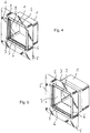
- zeigen das Behältnis in perspektivischer Darstellung von oben vorne rechts, und zwar in
Fig. 4 gemäßFig. 1 und inFig. 5 gemäßFig. 2 . - Die Figuren zeigen einen aus einem starren Kunststoff gespritzten oder tiefgezogenen oder aus Blech geschweißten oder tiefgezogenen Kasten 1 mit einer insbesondere in
Fig. 3 sichtbaren quadratischen Grundfläche und vier davon nach vorn abstehenden und miteinander verbundenen Wänden. In den Ecken zwischen diesen Wänden sind inFig. 4 und inFig. 1 und 2 (dort im Schnitt) gut sichtbare Rohrstücke 2 angebracht (oder im Spritzguss integriert), die ein Innengewinde aufweisen und in die eine jeweilige Gewindestange 3 eingreift. Ein Kopf jeder Gewindestange 3 ist dabei gehalten in einer Öse eines ebenfalls quadratischen Rahmens 4, der gemäß denFig. 1 und 2 ein flaches Profil aufweist mit längerer Profilrichtung senkrecht zur Wand und im Übrigen als geschlossener Rahmen die Außenkontur des quadratischen Grundrisses des Kastens 1 wieder aufnimmt. - Der Rahmen 4 ist ein spritzgegossenes Kunststoffteil, an das bei seiner Herstellung eine in den Figuren gut sichtbare Foliendichtung 5 an der (in den
Fig. 1 und 2 nach links weisenden) Vorderkante des Rahmens 4 angespritzt ist. Die Foliendichtung 5 ist also insgesamt flach und muss nicht tiefgezogen werden. Alternativ könnte sie um einen kleinen Streckenabschnitt an die Außenkante des Rahmens angepasst tiefgezogen und dann an den Rahmen von außen angeklebt sein, etwa wenn dieser aus Blech gefertigt sein soll. - Die Foliendichtung 5 besteht aus einer bevliesten Kunststofffolie mit einer gewissen Dehnbarkeit, womit sie gut und falten- und blasenfrei auf eine Badezimmerwand aufgeklebt werden kann.
- Zur Verbesserung der Stabilität der Foliendichtung 5 und der Anlage an der Wand weist diese an den geraden Kanten des quadratischen Rahmens 4 und zu dessen Flachprofil rechtwinklig und außen daran anschließende Leisten 6 auf, die die
Fig. 3 bis 5 am deutlichsten zeigen und die lediglich die Ecken des Rahmens aussparen. Sie sind getrennt von dem Rahmen 4 angeführt und können bei dem erwähnten (An-)Spritzprozess mit gespritzt werden. Daher sind sie zusammen mit der Foliendichtung 5 im Transport- und Auslieferungszustand nach innen in die Öffnung des Rahmens 4 eingeklappt und können in dieser Position z. B. durch einen Bauschutzdeckel von vorn geschützt sein. Nach Entfernung des Bauschutzdeckels kann dann die Foliendichtung 4 mit den Leisten 6 jeweils nach außen umgelegt werden, womit die in den Figuren dargestellte Situation entsteht. - In dieser Situation sorgen sie für eine flache faltenfreie Anlage der Foliendichtung 5 mindestens in einem an den Rahmen 4 anschließenden Bereich und erleichtern auch das Andrücken der Foliendichtung 5 an die Wand. Von den Leisten 6 ausgehend kann der Monteur dann die Foliendichtung nach außen glattstreichen, wobei eine gewisse Elastizität der Foliendichtung 5 hilfreich ist. Auf diese Weise kann also der Rahmen 4 mit Hilfe der Foliendichtung 5 fest und dicht mit der Wand verbunden werden.
- Der im Verhältnis zu der Foliendichtung 5 und der Verbindungswand 7 relativ starre Rahmen 4 erleichtert dabei dem Monteur die Arbeit, weil er eine definierte Bezugsgeometrie und insbesondere Bezugskanten vorgibt. Er fördert ferner einen sauberen und geometrietreuen Verlauf der Foliendichtung 5. Auch kann er bei entsprechender Ausgestaltung eine Anschlagkante zum Verlegen von Fliesen oder Platten oder zum Verputzen bilden.
- Gleichzeitig erlaubt die Erfindung eine gewisse Variabilität des Abstandes zwischen dem Rahmen 4 und dem Kasten 1 in einer zu der Wand und damit auch zu der vorderseitigen Öffnung in dem Kasten 1 senkrechten Richtung, also in den
Fig. 1 und 2 horizontal und inFig. 3 senkrecht auf der Zeichenebene. Dazu ist eine Verbindungswand 7 vorgesehen, die inFig. 1 und4 gefaltet und dabei maximal zusammengelegt und inFig. 2 und5 weitgehend faltenfrei straff gespannt ist. Dementsprechend ändert sich der erwähnte Abstand. - Dazu besteht die Verbindungswand aus einem dichten Kunststofffolienmaterial, das dehnbar sein kann, aber nicht muss, und in ähnlicher Weise wie die Foliendichtung 5 an dem Rahmen 4 und/oder den Seitenwänden des Kastens 1 angespritzt oder von außen oder von innen angeklebt sein kann. Zur Erleichterung des Zusammenfaltens kann das Folienmaterial zusätzlich z. B. durch Bügeln vorgeprägte Falten erhalten, in die es sich in dem in den
Fig. 1 und4 dargestellten Zustand legt. Die Verbindungswand 7 ist dementsprechend Garant für eine dichte Verbindung zwischen dem Rahmen 4 und dem Kasten 1 bei gleichzeitiger Einstellbarkeit des Abstandes dazwischen. - Dieser Abstand wiederum lässt sich mit Hilfe der bereits erwähnten Gewindestangen 3 einstellen, die in die Rohrstücke 2 eingreifen. Die Gewindestangen 3 sind dementsprechend durch Drehen relativ zu den Rohrstücken 2 und damit relativ zu dem Kasten 1 verstellbar. Durch entsprechende Einstellung geben sie entweder eine maximal nach vorn verlegte Position des Rahmens 4 vor, nämlich wenn dieser auf den Gewindestangen 3 gehalten und durch deren Köpfe nach vorn blockiert ist, oder definieren sogar dessen Position, nämlich wenn die Köpfe oder andere Teile der Gewindestangen 3 drehbar, aber axial nicht beliebig verschiebbar mit dem Rahmen 4 gekoppelt sind.
- In beiden Fällen kann der Monteur z. B. zunächst den Kasten 1 z. B. an einem aus dem Stand der Technik gut bekannten Montagegestell (wie es etwa zur Montage von Waschbecken, Hänge-WCs und Ähnlichem bekannt ist) anbringen. Dazu können z. B. von innen durch die Seitenwände des Kastens 1 in abgedichteter Weise Schrauben geführt werden oder kann der Kasten 1 z. B. mit äußeren Leisten 6 oder Nuten formschlüssig in entsprechende Montagestrukturen an dem Montagegestell (oder einer anderen Einrichtung der Wand) eingeschoben oder sonstwie formschlüssig befestigt werden.
- Dies kann auch noch vor der Herstellung der eigentlichen Wand, etwa einer Trockenbauwand bei der Herstellung oder Renovierung eines Badezimmers, geschehen. Dementsprechend steht zu diesem Zeitpunkt nicht unbedingt fest, wie stark (in der Richtung senkrecht zur Wand) der Wandaufbau insgesamt wird, etwa unter Berücksichtigung einer Fliesen- oder Natursteinverkleidung.
- Selbst wenn, ist es von großem Vorteil, durch die Variabilität des erfindungsgemäßen Behältnisses auf diese Stärke nicht schon bei der Montage des Kastens 1 genau Rücksicht nehmen zu müssen. Vielmehr kann der Monteur den Rahmen 4 mit Hilfe der Gewindestangen 3 auf eine gewünschte Position einstellen und damit z. B. eine bündige Anlage mit der Vorderseite der Wand, etwa den Fliesen, gewährleisten.
- Bei der dargestellten Variante ist hingegen vorgesehen, die Bündigkeit zu derjenigen Wandoberfläche herzustellen, auf die die Fliesen oder Natursteinplatten aufgebracht werden, wobei dann die Wandbedeckung, also etwa die Fliesen oder Natursteinplatten, nicht nur auf die Wand von außen aufgebracht werden, sondern auch in das Behältnis hinein und damit um die Vorderkante des Rahmens 4 herum. Bei nicht zu großer Ausdehnung der Verbindungswand in der Richtung senkrecht zur (Badezimmer-)Wand stören dabei die Flexibilität und möglicherweise Elastizität der Verbindungswand nicht, sondern kann diese überbrückt werden. Natürlich kann das Behältnis auch anderweitig ausgekleidet werden und kann der Rahmen 4 gegenüber der Foliendichtung 5 etwas vorne überstehen und im eingebauten und fertigen Zustand als bündige Anlagekante für z. B. Fliesen sichtbar sein.
- Im fertigen Zustand kann z. B. eine Wandnische zum Abstellen von z. B. Shampooflaschen oder zum Ablegen von Handtüchern im Duschbereich entstanden sein. Man kann natürlich auch noch regalähnliche Ablageboards einbauen oder sogar in das wasserdicht eingebaute Behältnis (ein z. B. weniger als Wandbestandteil, sondern als Möbel gestaltetes, auch kastenförmiges) Element mit entsprechenden Funktionen einschieben. Außerdem könnte das Behältnis auch zur leckagesicheren Unterbringung von Armaturen, Spülkästen oder ähnlichen Elementen dienen, was mit der Funktion als Stauraum oder Ablagebox kombiniert sein kann.
Claims (15)
- Behältnis zum abgedichteten Einbau in eine Wand, welches Behältnis aufweist:einen in Bezug auf eine eingebaute Position nach vorne offenen oder zu öffnenden und nach hinten und den übrigen Seiten geschlossenen Kasten (1), undeinen die Öffnung an der Vorderseite umlaufenden Rahmen (4),dadurch gekennzeichnet, dass der Rahmen (4) über eine bezüglich einer Bewegungsrichtung senkrecht zu der Öffnung nachgiebige Verbindungswand (7) mit dem Kasten (1) verbunden ist und gegenüber der Öffnung in der Richtung senkrecht zu der Öffnung in unterschiedlichem Maß versetzt montiert werden kann.
- Behältnis nach Anspruch 1, welches ferner eine den Rahmen (4) umlaufende und von dem Rahmen (4) in einer Ebene der vorderseitigen Öffnung nach außen wegstehende oder durch Umlegen in diese Lage bringbare, vorzugsweise flexible Dichtung (5) aufweist.
- Behältnis nach Anspruch 1 oder 2, das ferner von dem Rahmen (4) in einer Ebene der vorderseitigen Öffnung nach außen wegstehende oder durch Umlegen in diese Position bringbare starre Leisten (6) aufweist.
- Behältnis nach einem der vorstehenden Ansprüche, bei dem die Verbindungswand (7) aus einem flexiblen Material, vorzugsweise aus einer Folie, besteht.
- Behältnis nach einem der vorstehenden Ansprüche, welche ferner in der Bewegungsrichtung senkrecht zu der Vorderseite wirksame Verstellvorrichtung (2, 3) zum Verstellen eines Abstandes zwischen dem Rahmen (4) und dem Kasten (1) aufweist.
- Behältnis nach Anspruch 5, bei dem die Verstellvorrichtung (2, 3) mindestens eine Gewindestange (3) und ein Gegengewinde (2) zum Eingriff damit aufweist.
- Behältnis nach Anspruch 4, optional auch in Verbindung mit Anspruch 5 oder 6, bei welchem die Verbindungswand (7) aus dem flexiblen Material mindestens eine vorgeprägte, vorzugsweise gebügelte Falte zum Erleichtern eines Zusammenschiebens in der Bewegungsrichtung senkrecht zu der Vorderseite aufweist.
- Behältnis nach Anspruch 2, optional in Verbindung mit einem der Ansprüche 3 bis 7, bei dem der Rahmen (4) aus einem spritzbaren Kunststoff besteht und die Dichtung (5) an den Rahmen (4) angespritzt ist.
- Behältnis nach einem der vorstehenden Ansprüche, bei dem die Verbindungswand (7) an den Rahmen (4) und/oder den Kasten (1) angespritzt ist.
- Behältnis nach einem der vorstehenden Ansprüche, bei dem der Kasten (1) quaderförmig und der Rahmen (4) viereckig mit vorzugsweise der Umrandung der vorderseitigen Öffnung des Kastens (1) entsprechendem Format ist.
- Verwendung eines Behältnisses nach einem der vorstehenden Ansprüche zum Einbau in eine Wand, vorzugsweise eine Vorwand oder Trockenbauwand.
- Verwendung nach Anspruch 11, bei der die Wand eine Sanitärwand und vorzugsweise an einer Dusche vorgesehen ist.
- Verwendung nach Anspruch 11 oder 12, bei welcher das Behältnis innen verfliest wird und in dem verfliesten Bereich durch die Öffnung zugänglich ist.
- Verwendung nach einem der Ansprüche 11 bis 13, bei welcher das Behältnis als Ablage oder zur Aufnahme einer Ablage, vorzugsweise eines Ablagebords oder Regals, verwendet wird.
- Verwendung nach einem der Ansprüche 14, bei welcher das Behältnis als Leckageschutzeinrichtung für ein Wasserabgabegerät, insbesondere für einen Spülkasten, ein Spülventil, eine Armatur und/oder ein Mischventil verwendet wird.
Priority Applications (1)
| Application Number | Priority Date | Filing Date | Title |
|---|---|---|---|
| EP18155915.4A EP3524738B1 (de) | 2018-02-09 | 2018-02-09 | Behältnis zum abgedichteten einbau in eine wand |
Applications Claiming Priority (1)
| Application Number | Priority Date | Filing Date | Title |
|---|---|---|---|
| EP18155915.4A EP3524738B1 (de) | 2018-02-09 | 2018-02-09 | Behältnis zum abgedichteten einbau in eine wand |
Publications (2)
| Publication Number | Publication Date |
|---|---|
| EP3524738A1 true EP3524738A1 (de) | 2019-08-14 |
| EP3524738B1 EP3524738B1 (de) | 2020-04-01 |
Family
ID=61189256
Family Applications (1)
| Application Number | Title | Priority Date | Filing Date |
|---|---|---|---|
| EP18155915.4A Active EP3524738B1 (de) | 2018-02-09 | 2018-02-09 | Behältnis zum abgedichteten einbau in eine wand |
Country Status (1)
| Country | Link |
|---|---|
| EP (1) | EP3524738B1 (de) |
Cited By (3)
| Publication number | Priority date | Publication date | Assignee | Title |
|---|---|---|---|---|
| CN114250950A (zh) * | 2020-09-25 | 2022-03-29 | R.B.M.爱盒子有限责任公司 | 用于容纳液压组件的嵌入式盒子 |
| US20260028803A1 (en) * | 2024-07-24 | 2026-01-29 | Watts Regulator Co. | Plumbing box with adjustable backplate |
| DE202024106699U1 (de) * | 2024-11-20 | 2026-02-23 | Schlüter-Systems Kg | Einbauset zur Herstellung einer Wandnische |
Families Citing this family (2)
| Publication number | Priority date | Publication date | Assignee | Title |
|---|---|---|---|---|
| US11557888B2 (en) | 2019-02-14 | 2023-01-17 | Erico International Corporation | Adjustable depth electrical wall mount ring |
| WO2025132679A1 (de) * | 2023-12-20 | 2025-06-26 | Tece Gmbh | Wc-montagemodul mit leckageschutz |
Citations (3)
| Publication number | Priority date | Publication date | Assignee | Title |
|---|---|---|---|---|
| EP2441895A1 (de) * | 2010-10-14 | 2012-04-18 | Easy Sanitairy Solutions B.V. | Kombination von Spülkasten, Wand und Spültaste, wobei die Wand vor dem Spülkasten montiert ist |
| EP2821557A1 (de) * | 2013-07-05 | 2015-01-07 | Grohe AG | Einbauspüllkasten mit Leckageschutz |
| EP3222786A1 (de) * | 2016-03-23 | 2017-09-27 | Franke Aquarotter GmbH | Wandeinbaukasten |
-
2018
- 2018-02-09 EP EP18155915.4A patent/EP3524738B1/de active Active
Patent Citations (3)
| Publication number | Priority date | Publication date | Assignee | Title |
|---|---|---|---|---|
| EP2441895A1 (de) * | 2010-10-14 | 2012-04-18 | Easy Sanitairy Solutions B.V. | Kombination von Spülkasten, Wand und Spültaste, wobei die Wand vor dem Spülkasten montiert ist |
| EP2821557A1 (de) * | 2013-07-05 | 2015-01-07 | Grohe AG | Einbauspüllkasten mit Leckageschutz |
| EP3222786A1 (de) * | 2016-03-23 | 2017-09-27 | Franke Aquarotter GmbH | Wandeinbaukasten |
Cited By (4)
| Publication number | Priority date | Publication date | Assignee | Title |
|---|---|---|---|---|
| CN114250950A (zh) * | 2020-09-25 | 2022-03-29 | R.B.M.爱盒子有限责任公司 | 用于容纳液压组件的嵌入式盒子 |
| EP3974588A1 (de) * | 2020-09-25 | 2022-03-30 | Rbm Ibox S.R.L. | Einbaukasten zur aufnahme von hydraulikkomponenten |
| US20260028803A1 (en) * | 2024-07-24 | 2026-01-29 | Watts Regulator Co. | Plumbing box with adjustable backplate |
| DE202024106699U1 (de) * | 2024-11-20 | 2026-02-23 | Schlüter-Systems Kg | Einbauset zur Herstellung einer Wandnische |
Also Published As
| Publication number | Publication date |
|---|---|
| EP3524738B1 (de) | 2020-04-01 |
Similar Documents
| Publication | Publication Date | Title |
|---|---|---|
| EP3524738B1 (de) | Behältnis zum abgedichteten einbau in eine wand | |
| EP2540922B1 (de) | Überbausystem für einen im Bodenbereich befindlichen Ablauf | |
| EP2821557B1 (de) | Einbauspüllkasten mit Leckageschutz | |
| EP3138968A1 (de) | Einbauspülkasten mit feuchte- und leckageschutz | |
| EP3150094A1 (de) | Sanitäranordnung | |
| DE102012102929B4 (de) | Sanitäranordnung | |
| EP1779754A1 (de) | Duschboard mit Rinnensystem | |
| EP4273333A1 (de) | Wandeinbau-spülkasten mit leckageschutz | |
| EP3321429B1 (de) | Leckageschutz für einen spülkasten | |
| EP3501356B1 (de) | Sanitärinstallation | |
| EP0748179A1 (de) | Zarge zur herstellung von wandabschlüssen | |
| DE202012101292U1 (de) | Leiste, insbesondere Sockelleiste, Wandanschlussleiste oder dergleichen Abschlussleiste | |
| DE202018001321U1 (de) | Behältnis zum Wandeinbau | |
| DE202018000664U1 (de) | Behältnis zum abgedichteten Einbau in eine Wand | |
| EP3540136A1 (de) | Wandmontagevorrichtung | |
| AT517536B1 (de) | Einbaubox mit Beleuchtung für den Einbau in einer Wandnische oder Aussparung | |
| DE202014101798U1 (de) | Einbaubox für wandbündigen Einbau | |
| DE102013016103B4 (de) | Anschlusskörper für eine sanitare Unterputzarmatur | |
| DE202018001327U1 (de) | Behältnis zum abgedichteten Einbau in eine Wand | |
| EP3447204B1 (de) | Behältnis zum abgedichteten einbau in eine wand, verwendung der dichtung eines solchen behältnisses und sein herstellverfahren | |
| CH708365A2 (de) | Einbaubox für den wandbündigen Einbau. | |
| DE102013017569A1 (de) | Duschboden | |
| CH690162A5 (de) | Zarge zur Herstellung von Wandabschlüssen | |
| DE19503514A1 (de) | Duschbadewanne | |
| DE1683445A1 (de) | Vorrichtung in Gestalt eines Rahmens oder Rahmenteiles zum Ausfuellen von Fugen oder Rinnen |
Legal Events
| Date | Code | Title | Description |
|---|---|---|---|
| PUAI | Public reference made under article 153(3) epc to a published international application that has entered the european phase |
Free format text: ORIGINAL CODE: 0009012 |
|
| STAA | Information on the status of an ep patent application or granted ep patent |
Free format text: STATUS: REQUEST FOR EXAMINATION WAS MADE |
|
| 17P | Request for examination filed |
Effective date: 20180906 |
|
| AK | Designated contracting states |
Kind code of ref document: A1 Designated state(s): AL AT BE BG CH CY CZ DE DK EE ES FI FR GB GR HR HU IE IS IT LI LT LU LV MC MK MT NL NO PL PT RO RS SE SI SK SM TR |
|
| AX | Request for extension of the european patent |
Extension state: BA ME |
|
| GRAP | Despatch of communication of intention to grant a patent |
Free format text: ORIGINAL CODE: EPIDOSNIGR1 |
|
| STAA | Information on the status of an ep patent application or granted ep patent |
Free format text: STATUS: GRANT OF PATENT IS INTENDED |
|
| RIC1 | Information provided on ipc code assigned before grant |
Ipc: H02G 3/08 20060101ALI20190930BHEP Ipc: E03B 7/09 20060101AFI20190930BHEP Ipc: E03C 1/02 20060101ALI20190930BHEP Ipc: E03D 1/012 20060101ALI20190930BHEP |
|
| INTG | Intention to grant announced |
Effective date: 20191024 |
|
| GRAJ | Information related to disapproval of communication of intention to grant by the applicant or resumption of examination proceedings by the epo deleted |
Free format text: ORIGINAL CODE: EPIDOSDIGR1 |
|
| STAA | Information on the status of an ep patent application or granted ep patent |
Free format text: STATUS: REQUEST FOR EXAMINATION WAS MADE |
|
| GRAP | Despatch of communication of intention to grant a patent |
Free format text: ORIGINAL CODE: EPIDOSNIGR1 |
|
| STAA | Information on the status of an ep patent application or granted ep patent |
Free format text: STATUS: GRANT OF PATENT IS INTENDED |
|
| INTC | Intention to grant announced (deleted) | ||
| GRAS | Grant fee paid |
Free format text: ORIGINAL CODE: EPIDOSNIGR3 |
|
| INTG | Intention to grant announced |
Effective date: 20200129 |
|
| GRAA | (expected) grant |
Free format text: ORIGINAL CODE: 0009210 |
|
| STAA | Information on the status of an ep patent application or granted ep patent |
Free format text: STATUS: THE PATENT HAS BEEN GRANTED |
|
| RBV | Designated contracting states (corrected) |
Designated state(s): AL AT BE BG CH CY CZ DE DK EE ES FI FR GB GR HR HU IE IS IT LI LT LU LV MC MK MT NL NO PL PT RO RS SE SI SK SM TR |
|
| AK | Designated contracting states |
Kind code of ref document: B1 Designated state(s): AL AT BE BG CH CY CZ DE DK EE ES FI FR GB GR HR HU IE IS IT LI LT LU LV MC MK MT NL NO PL PT RO RS SE SI SK SM TR |
|
| REG | Reference to a national code |
Ref country code: GB Ref legal event code: FG4D Free format text: NOT ENGLISH |
|
| REG | Reference to a national code |
Ref country code: AT Ref legal event code: REF Ref document number: 1251485 Country of ref document: AT Kind code of ref document: T Effective date: 20200415 Ref country code: CH Ref legal event code: EP |
|
| REG | Reference to a national code |
Ref country code: DE Ref legal event code: R096 Ref document number: 502018001056 Country of ref document: DE |
|
| REG | Reference to a national code |
Ref country code: IE Ref legal event code: FG4D Free format text: LANGUAGE OF EP DOCUMENT: GERMAN |
|
| REG | Reference to a national code |
Ref country code: CH Ref legal event code: NV Representative=s name: TR-IP CONSULTING LLC, CH |
|
| PG25 | Lapsed in a contracting state [announced via postgrant information from national office to epo] |
Ref country code: BG Free format text: LAPSE BECAUSE OF FAILURE TO SUBMIT A TRANSLATION OF THE DESCRIPTION OR TO PAY THE FEE WITHIN THE PRESCRIBED TIME-LIMIT Effective date: 20200701 |
|
| REG | Reference to a national code |
Ref country code: NL Ref legal event code: MP Effective date: 20200401 |
|
| REG | Reference to a national code |
Ref country code: LT Ref legal event code: MG4D |
|
| PG25 | Lapsed in a contracting state [announced via postgrant information from national office to epo] |
Ref country code: FI Free format text: LAPSE BECAUSE OF FAILURE TO SUBMIT A TRANSLATION OF THE DESCRIPTION OR TO PAY THE FEE WITHIN THE PRESCRIBED TIME-LIMIT Effective date: 20200401 Ref country code: SE Free format text: LAPSE BECAUSE OF FAILURE TO SUBMIT A TRANSLATION OF THE DESCRIPTION OR TO PAY THE FEE WITHIN THE PRESCRIBED TIME-LIMIT Effective date: 20200401 Ref country code: CZ Free format text: LAPSE BECAUSE OF FAILURE TO SUBMIT A TRANSLATION OF THE DESCRIPTION OR TO PAY THE FEE WITHIN THE PRESCRIBED TIME-LIMIT Effective date: 20200401 Ref country code: NL Free format text: LAPSE BECAUSE OF FAILURE TO SUBMIT A TRANSLATION OF THE DESCRIPTION OR TO PAY THE FEE WITHIN THE PRESCRIBED TIME-LIMIT Effective date: 20200401 Ref country code: PT Free format text: LAPSE BECAUSE OF FAILURE TO SUBMIT A TRANSLATION OF THE DESCRIPTION OR TO PAY THE FEE WITHIN THE PRESCRIBED TIME-LIMIT Effective date: 20200817 Ref country code: LT Free format text: LAPSE BECAUSE OF FAILURE TO SUBMIT A TRANSLATION OF THE DESCRIPTION OR TO PAY THE FEE WITHIN THE PRESCRIBED TIME-LIMIT Effective date: 20200401 Ref country code: GR Free format text: LAPSE BECAUSE OF FAILURE TO SUBMIT A TRANSLATION OF THE DESCRIPTION OR TO PAY THE FEE WITHIN THE PRESCRIBED TIME-LIMIT Effective date: 20200702 Ref country code: NO Free format text: LAPSE BECAUSE OF FAILURE TO SUBMIT A TRANSLATION OF THE DESCRIPTION OR TO PAY THE FEE WITHIN THE PRESCRIBED TIME-LIMIT Effective date: 20200701 Ref country code: IS Free format text: LAPSE BECAUSE OF FAILURE TO SUBMIT A TRANSLATION OF THE DESCRIPTION OR TO PAY THE FEE WITHIN THE PRESCRIBED TIME-LIMIT Effective date: 20200801 |
|
| PG25 | Lapsed in a contracting state [announced via postgrant information from national office to epo] |
Ref country code: RS Free format text: LAPSE BECAUSE OF FAILURE TO SUBMIT A TRANSLATION OF THE DESCRIPTION OR TO PAY THE FEE WITHIN THE PRESCRIBED TIME-LIMIT Effective date: 20200401 Ref country code: LV Free format text: LAPSE BECAUSE OF FAILURE TO SUBMIT A TRANSLATION OF THE DESCRIPTION OR TO PAY THE FEE WITHIN THE PRESCRIBED TIME-LIMIT Effective date: 20200401 Ref country code: HR Free format text: LAPSE BECAUSE OF FAILURE TO SUBMIT A TRANSLATION OF THE DESCRIPTION OR TO PAY THE FEE WITHIN THE PRESCRIBED TIME-LIMIT Effective date: 20200401 |
|
| PG25 | Lapsed in a contracting state [announced via postgrant information from national office to epo] |
Ref country code: AL Free format text: LAPSE BECAUSE OF FAILURE TO SUBMIT A TRANSLATION OF THE DESCRIPTION OR TO PAY THE FEE WITHIN THE PRESCRIBED TIME-LIMIT Effective date: 20200401 |
|
| REG | Reference to a national code |
Ref country code: DE Ref legal event code: R097 Ref document number: 502018001056 Country of ref document: DE |
|
| PG25 | Lapsed in a contracting state [announced via postgrant information from national office to epo] |
Ref country code: DK Free format text: LAPSE BECAUSE OF FAILURE TO SUBMIT A TRANSLATION OF THE DESCRIPTION OR TO PAY THE FEE WITHIN THE PRESCRIBED TIME-LIMIT Effective date: 20200401 Ref country code: EE Free format text: LAPSE BECAUSE OF FAILURE TO SUBMIT A TRANSLATION OF THE DESCRIPTION OR TO PAY THE FEE WITHIN THE PRESCRIBED TIME-LIMIT Effective date: 20200401 Ref country code: SM Free format text: LAPSE BECAUSE OF FAILURE TO SUBMIT A TRANSLATION OF THE DESCRIPTION OR TO PAY THE FEE WITHIN THE PRESCRIBED TIME-LIMIT Effective date: 20200401 Ref country code: RO Free format text: LAPSE BECAUSE OF FAILURE TO SUBMIT A TRANSLATION OF THE DESCRIPTION OR TO PAY THE FEE WITHIN THE PRESCRIBED TIME-LIMIT Effective date: 20200401 Ref country code: ES Free format text: LAPSE BECAUSE OF FAILURE TO SUBMIT A TRANSLATION OF THE DESCRIPTION OR TO PAY THE FEE WITHIN THE PRESCRIBED TIME-LIMIT Effective date: 20200401 |
|
| PLBE | No opposition filed within time limit |
Free format text: ORIGINAL CODE: 0009261 |
|
| STAA | Information on the status of an ep patent application or granted ep patent |
Free format text: STATUS: NO OPPOSITION FILED WITHIN TIME LIMIT |
|
| PG25 | Lapsed in a contracting state [announced via postgrant information from national office to epo] |
Ref country code: PL Free format text: LAPSE BECAUSE OF FAILURE TO SUBMIT A TRANSLATION OF THE DESCRIPTION OR TO PAY THE FEE WITHIN THE PRESCRIBED TIME-LIMIT Effective date: 20200401 Ref country code: SK Free format text: LAPSE BECAUSE OF FAILURE TO SUBMIT A TRANSLATION OF THE DESCRIPTION OR TO PAY THE FEE WITHIN THE PRESCRIBED TIME-LIMIT Effective date: 20200401 |
|
| 26N | No opposition filed |
Effective date: 20210112 |
|
| PG25 | Lapsed in a contracting state [announced via postgrant information from national office to epo] |
Ref country code: MC Free format text: LAPSE BECAUSE OF FAILURE TO SUBMIT A TRANSLATION OF THE DESCRIPTION OR TO PAY THE FEE WITHIN THE PRESCRIBED TIME-LIMIT Effective date: 20200401 |
|
| REG | Reference to a national code |
Ref country code: BE Ref legal event code: MM Effective date: 20210228 |
|
| PG25 | Lapsed in a contracting state [announced via postgrant information from national office to epo] |
Ref country code: LU Free format text: LAPSE BECAUSE OF NON-PAYMENT OF DUE FEES Effective date: 20210209 |
|
| PG25 | Lapsed in a contracting state [announced via postgrant information from national office to epo] |
Ref country code: IE Free format text: LAPSE BECAUSE OF NON-PAYMENT OF DUE FEES Effective date: 20210209 |
|
| PG25 | Lapsed in a contracting state [announced via postgrant information from national office to epo] |
Ref country code: BE Free format text: LAPSE BECAUSE OF NON-PAYMENT OF DUE FEES Effective date: 20210228 |
|
| P01 | Opt-out of the competence of the unified patent court (upc) registered |
Effective date: 20230507 |
|
| PG25 | Lapsed in a contracting state [announced via postgrant information from national office to epo] |
Ref country code: CY Free format text: LAPSE BECAUSE OF FAILURE TO SUBMIT A TRANSLATION OF THE DESCRIPTION OR TO PAY THE FEE WITHIN THE PRESCRIBED TIME-LIMIT Effective date: 20200401 |
|
| PG25 | Lapsed in a contracting state [announced via postgrant information from national office to epo] |
Ref country code: HU Free format text: LAPSE BECAUSE OF FAILURE TO SUBMIT A TRANSLATION OF THE DESCRIPTION OR TO PAY THE FEE WITHIN THE PRESCRIBED TIME-LIMIT; INVALID AB INITIO Effective date: 20180209 |
|
| PG25 | Lapsed in a contracting state [announced via postgrant information from national office to epo] |
Ref country code: SI Free format text: LAPSE BECAUSE OF FAILURE TO SUBMIT A TRANSLATION OF THE DESCRIPTION OR TO PAY THE FEE WITHIN THE PRESCRIBED TIME-LIMIT Effective date: 20200401 |
|
| PG25 | Lapsed in a contracting state [announced via postgrant information from national office to epo] |
Ref country code: MK Free format text: LAPSE BECAUSE OF FAILURE TO SUBMIT A TRANSLATION OF THE DESCRIPTION OR TO PAY THE FEE WITHIN THE PRESCRIBED TIME-LIMIT Effective date: 20200401 |
|
| PG25 | Lapsed in a contracting state [announced via postgrant information from national office to epo] |
Ref country code: TR Free format text: LAPSE BECAUSE OF FAILURE TO SUBMIT A TRANSLATION OF THE DESCRIPTION OR TO PAY THE FEE WITHIN THE PRESCRIBED TIME-LIMIT Effective date: 20200401 |
|
| PG25 | Lapsed in a contracting state [announced via postgrant information from national office to epo] |
Ref country code: MT Free format text: LAPSE BECAUSE OF FAILURE TO SUBMIT A TRANSLATION OF THE DESCRIPTION OR TO PAY THE FEE WITHIN THE PRESCRIBED TIME-LIMIT Effective date: 20200401 |
|
| REG | Reference to a national code |
Ref country code: AT Ref legal event code: PC Ref document number: 1251485 Country of ref document: AT Kind code of ref document: T Owner name: GEBERIT INTERNATIONAL AG, CH Effective date: 20241118 |
|
| REG | Reference to a national code |
Ref country code: DE Ref legal event code: R082 Ref document number: 502018001056 Country of ref document: DE Representative=s name: SZYNKA SMORODIN PATENTANWAELTE PARTNERSCHAFT M, DE |
|
| REG | Reference to a national code |
Ref country code: CH Ref legal event code: R17 Free format text: ST27 STATUS EVENT CODE: U-0-0-R10-R17 (AS PROVIDED BY THE NATIONAL OFFICE) Effective date: 20251024 |
|
| REG | Reference to a national code |
Ref country code: CH Ref legal event code: U11 Free format text: ST27 STATUS EVENT CODE: U-0-0-U10-U11 (AS PROVIDED BY THE NATIONAL OFFICE) Effective date: 20260301 |
|
| PGFP | Annual fee paid to national office [announced via postgrant information from national office to epo] |
Ref country code: GB Payment date: 20260219 Year of fee payment: 9 |
|
| PGFP | Annual fee paid to national office [announced via postgrant information from national office to epo] |
Ref country code: DE Payment date: 20260217 Year of fee payment: 9 |
|
| PGFP | Annual fee paid to national office [announced via postgrant information from national office to epo] |
Ref country code: AT Payment date: 20260216 Year of fee payment: 9 |
|
| PGFP | Annual fee paid to national office [announced via postgrant information from national office to epo] |
Ref country code: IT Payment date: 20260227 Year of fee payment: 9 |
|
| PGFP | Annual fee paid to national office [announced via postgrant information from national office to epo] |
Ref country code: FR Payment date: 20260223 Year of fee payment: 9 |
|
| PGFP | Annual fee paid to national office [announced via postgrant information from national office to epo] |
Ref country code: CH Payment date: 20260301 Year of fee payment: 9 |