EP3524545A1 - Förderanlage - Google Patents
Förderanlage Download PDFInfo
- Publication number
- EP3524545A1 EP3524545A1 EP19155860.0A EP19155860A EP3524545A1 EP 3524545 A1 EP3524545 A1 EP 3524545A1 EP 19155860 A EP19155860 A EP 19155860A EP 3524545 A1 EP3524545 A1 EP 3524545A1
- Authority
- EP
- European Patent Office
- Prior art keywords
- path
- conveyance
- traveling
- carrier
- support
- Prior art date
- Legal status (The legal status is an assumption and is not a legal conclusion. Google has not performed a legal analysis and makes no representation as to the accuracy of the status listed.)
- Granted
Links
- 239000000969 carrier Substances 0.000 description 26
- 238000009825 accumulation Methods 0.000 description 25
- 230000002093 peripheral effect Effects 0.000 description 18
- 230000005540 biological transmission Effects 0.000 description 11
- 238000011144 upstream manufacturing Methods 0.000 description 8
- 239000000463 material Substances 0.000 description 7
- 230000008602 contraction Effects 0.000 description 3
- 239000000725 suspension Substances 0.000 description 3
- 230000015572 biosynthetic process Effects 0.000 description 1
- 238000009751 slip forming Methods 0.000 description 1
Images


Classifications
-
- B—PERFORMING OPERATIONS; TRANSPORTING
- B65—CONVEYING; PACKING; STORING; HANDLING THIN OR FILAMENTARY MATERIAL
- B65G—TRANSPORT OR STORAGE DEVICES, e.g. CONVEYORS FOR LOADING OR TIPPING, SHOP CONVEYOR SYSTEMS OR PNEUMATIC TUBE CONVEYORS
- B65G9/00—Apparatus for assisting manual handling having suspended load-carriers movable by hand or gravity
- B65G9/008—Rails or switches
-
- B—PERFORMING OPERATIONS; TRANSPORTING
- B61—RAILWAYS
- B61B—RAILWAY SYSTEMS; EQUIPMENT THEREFOR NOT OTHERWISE PROVIDED FOR
- B61B10/00—Power and free systems
- B61B10/02—Power and free systems with suspended vehicles
- B61B10/025—Coupling and uncoupling means between power track abd vehicles
-
- B—PERFORMING OPERATIONS; TRANSPORTING
- B65—CONVEYING; PACKING; STORING; HANDLING THIN OR FILAMENTARY MATERIAL
- B65G—TRANSPORT OR STORAGE DEVICES, e.g. CONVEYORS FOR LOADING OR TIPPING, SHOP CONVEYOR SYSTEMS OR PNEUMATIC TUBE CONVEYORS
- B65G19/00—Conveyors comprising an impeller or a series of impellers carried by an endless traction element and arranged to move articles or materials over a supporting surface or underlying material, e.g. endless scraper conveyors
- B65G19/02—Conveyors comprising an impeller or a series of impellers carried by an endless traction element and arranged to move articles or materials over a supporting surface or underlying material, e.g. endless scraper conveyors for articles, e.g. for containers
- B65G19/025—Conveyors comprising an impeller or a series of impellers carried by an endless traction element and arranged to move articles or materials over a supporting surface or underlying material, e.g. endless scraper conveyors for articles, e.g. for containers for suspended articles
-
- B—PERFORMING OPERATIONS; TRANSPORTING
- B65—CONVEYING; PACKING; STORING; HANDLING THIN OR FILAMENTARY MATERIAL
- B65G—TRANSPORT OR STORAGE DEVICES, e.g. CONVEYORS FOR LOADING OR TIPPING, SHOP CONVEYOR SYSTEMS OR PNEUMATIC TUBE CONVEYORS
- B65G35/00—Mechanical conveyors not otherwise provided for
- B65G35/06—Mechanical conveyors not otherwise provided for comprising a load-carrier moving along a path, e.g. a closed path, and adapted to be engaged by any one of a series of traction elements spaced along the path
-
- B—PERFORMING OPERATIONS; TRANSPORTING
- B65—CONVEYING; PACKING; STORING; HANDLING THIN OR FILAMENTARY MATERIAL
- B65G—TRANSPORT OR STORAGE DEVICES, e.g. CONVEYORS FOR LOADING OR TIPPING, SHOP CONVEYOR SYSTEMS OR PNEUMATIC TUBE CONVEYORS
- B65G2201/00—Indexing codes relating to handling devices, e.g. conveyors, characterised by the type of product or load being conveyed or handled
- B65G2201/02—Articles
Definitions
- the present invention relates to a conveyance facility for conveying articles along a conveyance path, in particular to a conveyance facility for suspended conveyance of the articles.
- a conventional conveyance facility for suspended conveyance of articles is shown in European Patent No. 2117972 .
- the conveyance facility shown in European Patent No. 2117972 includes a first conveyance lane causing carriers (conveyance unit) for the suspended conveyance of the articles, to travel along a conveyance path; and a branch conveyance lane and a second conveyance lane provided so as to branch from the first conveyance lane and causing the carriers to travel along the conveyance path.
- the first conveyance lane, the branch conveyance lane, and the second conveyance lane include a first guide rail, a branch guide rail, and a second guide rail, respectively.
- the first guide rail, the branch guide rail, and the second guide rail engage with a traveling roller (traveling body) of each of the carriers to cause the carrier to travel.
- a switching device is provided at a branch portion between the first conveyance lane and the branch conveyance lane. The switching device switches the carrier from the first guide rail to the branch guide rail.
- the switching device includes a guide band material for causing the carrier to travel along the first conveyance lane (first guide rail); and a diverter switch blade for causing the carrier to travel along the branch conveyance lane (branch guide rail).
- the switching device causes either one of the guide band material or the diverter switch blade to engage with the carrier.
- the switching device thereby causes the carrier to travel along the first guide rail or the branch guide rail.
- An object of the present invention is to provide a conveyance facility capable of reliably switching the conveyance path of the conveyance unit at the branch portion between a first conveyance path of the conveyance unit and a second conveyance path branching from somewhere in the middle of the first conveyance path.
- a conveyance facility of the present invention is a conveyance facility for conveying an article along a conveyance path, including: a conveyance unit including a traveling body traveling on the conveyance path, and a support traveling with the traveling body and supporting the article being suspended, the conveyance unit conveying the article along the conveyance path; and a traveling rail supporting the traveling body so as to be travelable, wherein the traveling rail forms a first conveyance path, and a second conveyance path branching from somewhere in the middle of the first conveyance path, wherein a switching device for switching the conveyance path of the conveyance unit from the first conveyance path to the second conveyance path is provided at a branch portion between the first conveyance path and the second conveyance path, and wherein the switching device is capable of directing the support from the first conveyance path to the second conveyance path.
- the conveyance path of the support is switched from the first conveyance path to the second conveyance path, by the switching device.
- the switching device includes a guide member guiding the support in a predetermined direction; and the direction of guiding the support by the guide member is switchable by the switching device so as to be capable of directing the support from the first conveyance path to the second conveyance path.
- the conveyance path is switched from the first conveyance path to the second conveyance path by switching the direction of guiding the support by the guide member.
- the traveling rail includes a first guide rail guiding an upper portion of the support along the first conveyance path, and a second guide rail guiding the upper portion of the support along the second conveyance path; and the guide member supports and guides the upper portion of the support, and is capable of switching the direction of guiding the support, from the first guide rail to the second guide rail.
- the conveyance path is switched from the first conveyance path to the second conveyance path by switching the direction of guiding by the guide member supporting and guiding the upper portion of the support.
- the switching device includes a towing portion towing the guide member; and the guide member is capable of switching a traveling direction of the support, through the towing by the towing portion.
- the towing portion tows the guide member.
- the direction of guiding the support by the guide member is switched from a direction of guiding the support toward the first conveyance path, to a direction of guiding the support toward the second conveyance path.
- a traveling path of the conveyance unit is switched from the first conveyance path to the second conveyance path.
- the switching device for switching the conveyance path of the conveyance unit can direct the support of the conveyance unit from the first conveyance path to the second conveyance path.
- the conveyance unit can be caused to travel from the first conveyance path toward the second conveyance path while the support of the conveyance unit is directed from the first conveyance path to the second conveyance path by the switching device. Accordingly, when the entire conveyance unit travels from the first conveyance path toward the second conveyance path, the conveyance path of the conveyance unit can be reliably switched at the branch portion without bouncing up of the conveyance unit or the like.
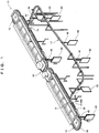
- a conveyance facility 10 according to the present invention will be described.
- the present invention is not limited to the conveyance facility 10 to be shown below.
- the conveyance facility 10 is a suspended conveyance facility for suspended conveyance of bags 90 (an example of "article") containing goods.
- the conveyance facility 10 includes a first path 11 (an example of “conveyance path” and “first conveyance path”) and a second path 12 (an example of “conveyance path”) for circularly conveying the bags 90, as well as a detour path 13 (an example of "conveyance path” and “second conveyance path”) branching from somewhere in the middle of the first path 11 and joining the second path 12.
- the first path 11 and the second path 12 include loop-like conveyance paths.
- the first path 11 and the second path 12 have swivel paths on both end portions, respectively.
- the first path 11 and the second path 12 are serially arranged so that the swivel paths on the respective ones of the end portions face each other.
- a branch portion 14 is provided at a joint section between the first path 11 and the second path 12 (a portion where the swivel paths face each other).
- the branch portion 14 keeps the bags 90 being circularly conveyed on the first path 11 so as to be circularly conveyed on the first path 11.
- the branch portion 14 causes the bags 90 being circularly conveyed on the first path 11 to be conveyed on the second path 12 through intersection of the branch portion 14.
- the branch portion 14 keeps the bags 90 being circularly conveyed on the second path 12 so as to be circularly conveyed on the second path 12.
- the branch portion 14 causes the bags 90 being circularly conveyed on the second path 12 to be conveyed on the first path 11 through the intersection of the branch portion 14.
- the detour path 13 is a conveyance path for causing the bags 90 conveyed on the first path 11 to detour without the branch portion 14 so as to join the second path 12.
- a beginning portion of the detour path 13 branches somewhere in the middle of the first path 11.
- An ending portion of the detour path 13 joins the second path 12.
- a branch portion 15 is provided at the beginning portion of the detour path 13 (a connecting portion between the detour path 13 and the first path 11).
- the branch portion 15 is a portion where the detour path 13 branches from somewhere in the middle of the first path 11.
- the branch portion 15 keeps the bags 90 conveyed on the first path 11 so as to be conveyed on the first path 11.
- the branch portion 15 causes some of the bags 90 conveyed on the first path 11 to branch from the first path 11 to the detour path 13 for conveyance.
- the branch portion 15 will be described later.
- a joint portion 16 is provided at the ending portion of the detour path 13 (a connecting portion between the detour path 13 and the second path 12).
- the joint portion 16 is a portion where the detour path 13 joins the second path 12.
- the joint portion 16 keeps the bags 90 conveyed on the second path 12 so as to be conveyed on the second path 12.
- the joint portion 16 causes the bags 90 conveyed on the detour path 13 to join the second path 12.
- a sending device 20 is provided on an upstream side of the branch portion 15.
- the sending device 20 is a device for sending out multiple carriers 40 (an example of "conveyance unit") traveling with the bags 90 being suspended, at predetermined intervals.
- the sending device 20 causes the multiple carriers 40 continuously traveling toward the branch portion 15 to stop once, and causes the adjacent carriers 40 to sequentially travel at the predetermined intervals.
- the sending device 20 includes a first stopper 21 and a second stopper 22 for stopping the carriers 40, and a cam mechanism 23 for moving the first stopper 21 and the second stopper 22.
- the first stopper 21 and the second stopper 22 are lengthy members extended orthogonally to a horizontal direction, with respect to a traveling direction of the carriers 40 traveling in the horizontal direction.
- the first stopper 21 and the second stopper 22 are driven by the cam mechanism 23 so as to move outward and backward with respect to the horizontal direction.
- Tip end portions of the first stopper 21 and the second stopper 22 move forward with respect to the horizontal direction so as to abut a front surface of each of the carriers 40 in the traveling direction to stop the carrier 40.
- the tip end portions of the first stopper 21 and the second stopper 22 move backward with respect to the horizontal direction so as to cancel the stop of the carrier 40 caused by the tip end portions.
- the first stopper 21 is arranged closer to an upstream side of the sending device 20 than the second stopper 22.
- the cam mechanism 23 includes a cam body 23A causing the first stopper 21 and the second stopper 22 to alternately move outward and backward, an arm 23B swinging the cam body 23A, and a drive motor 23C driving the arm 23B.
- the cam mechanism 23 drives the drive motor 23C to operate the arm 23B so as to swing the cam body 23A.
- the first stopper 21 and the second stopper 22 thereby alternately move outward and backward with respect to the horizontal direction.
- the sending device 20 causes the first stopper 21 and the second stopper 22 to alternately move outward and backward, and shifts timings of the carriers 40 passing through the sending device 20, so as to have the predetermined intervals between the adjacent carriers 40.
- the tip end portion of the first stopper 21 abuts the front surface of the carrier 40 traveling from the upstream side of the sending device 20, in the traveling direction.
- the carrier 40 traveling from the upstream side of the sending device 20 is thereby stopped by the first stopper 21.
- the cam mechanism 23 is driven to cause the first stopper 21 to move backward and also cause the second stopper 22 to move forward.
- the carrier 40 stopped by the first stopper 21 thereby travels to a downstream side, and is stopped again by the second stopper 22.
- the cam mechanism 23 is driven to cause the first stopper 21 to move forward and also cause the second stopper 22 to move backward.
- the carrier 40 stopped by the second stopper 22 thereby travels to the downstream side, and the subsequent carrier 40 is stopped by the first stopper 21.
- the alternate movement of the first stopper 21 and the second stopper 22 causes only one carrier 40 to pass between the first stopper 21 and the second stopper 22.
- the adjacent carriers 40 (bags 90) thereby travel at the predetermined intervals.
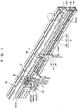
- a branch unit 60 (an example of "switching device") is provided at the branch portion 15 of the first path 11.
- the branch unit 60 is a device for switching the conveyance path of the bags 90 conveyed on the first path 11, to the detour path 13.
- the branch unit 60 includes a branch device 61 for switching the traveling path of the carriers 40.
- the branch unit 60 actuates the branch device 61 to direct the carriers 40 traveling on the first path 11, to the detour path 13.
- the conveyance path of the bags 90 (carriers 40) conveyed from the first path 11 is thereby switched to the detour path 13.
- the branch unit 60 will be described later.
- the conveyance facility 10 includes traveling rails 30 formed along the respective conveyance paths (the first path 11, the second path 12, and the detour path 13), and the carriers 40 being supported so as to be travelable by the traveling rails 30 and supporting the bags 90 being suspended.
- Each of the traveling rails 30 is a frame material formed with an upper portion projecting more than a lower portion in the horizontal direction.
- the frame material is substantially reverse L-shaped as viewed from the side.
- the traveling rails 30 are extended along the respective conveyance paths (the first path 11, the second path 12, and the detour path 13).
- the traveling rail 30 supports a traveling wheel 41 of the carrier 40 so as to be travelable, as will be described.
- a guide groove 31 (an example of "first guide rail") guiding an upper portion of the carrier 40, a wheel support groove 32 supporting the traveling wheel 41 of the carrier 40 so as to be travelable, an upper belt groove 33 supporting an accumulation belt 50, and a lower belt groove 34 supporting a tracking conveyance belt 52 are extended in a longitudinal direction.
- the traveling rail 30 is formed with the guide groove 31, the wheel support groove 32, the upper belt groove 33, and the lower belt groove 34, in order from the upper portion of the frame material.
- the tracking conveyance belt 52 is arranged lower than the accumulation belt 50 in the traveling rail 30.
- the accumulation belt 50 is arranged on the side of the traveling wheel 41 of the carrier 40 supported by the traveling rail 30.
- the guide groove 31 is a groove-like portion (concave portion) formed at the upper portion (portion projecting in the horizontal direction) of the traveling rail 30.
- the groove-like portion opens in a vertical direction.
- the guide groove 31 is formed at the upper portion of the traveling rail 30 so as to cover the upper portion of the traveling carrier 40.
- the guide groove 31 holds an upper side surface of the carrier 40 in the groove-like portion, and guides the upper portion of the carrier 40 along the respective conveyance paths (the first path 11, the second path 12, and the detour path 13).
- the wheel support groove 32 is a groove-like portion (concave portion) formed at an upper side surface of the traveling rail 30.
- the groove-like portion opens in the horizontal direction.
- the wheel support groove 32 can cause the traveling wheel 41 of the carrier 40 to travel.
- a lower edge portion 32A of the groove-like portion of the wheel support groove 32 is formed in accordance with the shape of the traveling wheel 41.
- the wheel support groove 32 supports the traveling wheel 41 so as to be travelable, at the edge portion 32A.
- the upper belt groove 33 is a groove-like portion (concave portion) formed at a central side surface of the traveling rail 30.
- the groove-like portion opens in the horizontal direction.
- the accumulation belt 50 can stand in the vertical direction so as to fit the upper belt groove 33.
- the upper belt groove 33 can cause the circular accumulation belt 50 to circle along a side surface of the traveling rail 30.
- the upper belt groove 33 movably supports the accumulation belt 50 along the side surface of the traveling rail 30.
- the lower belt groove 34 is a groove-like portion (concave portion) formed at a lower side surface of the traveling rail 30.
- the groove-like portion opens in the horizontal direction.
- the tracking conveyance belt 52 can stand in the vertical direction so as to fit the lower belt groove 34.
- the lower belt groove 34 can cause the circular tracking conveyance belt 52 to circle along the side surface of the traveling rail 30.
- the lower belt groove 34 movably supports the tracking conveyance belt 52 along the side surface of the traveling rail 30.
- the carrier 40 includes the traveling wheel 41 (an example of "traveling body") supported so as to be travelable with respect to the traveling rail 30, and a support 42 supporting the bag 90 being suspended.
- the traveling wheel 41 an example of "traveling body” supported so as to be travelable with respect to the traveling rail 30, and a support 42 supporting the bag 90 being suspended.
- the traveling wheel 41 includes a pair of substantially cone-shaped wheels.
- the traveling wheel 41 is turnably supported by an upper portion of the support 42.
- one wheel of the pair of wheels is placed in the wheel support groove 32 of the traveling rail 30, and is supported so as to be travelable.
- the support 42 mainly includes a body portion 43 as a main body portion of the support 42, a suspension portion 44 provided at a lower portion of the body portion 43 so as to support the bag 90 being suspended, and a head portion 45 (an example of "upper portion of the support") provided at an upper portion of the body portion 43 so as to be guided by the traveling rail 30.
- the body portion 43 is composed of a lengthy plate-like member.
- a wheel support portion 43A turnably supporting the traveling wheel 41, a contact portion 43B coming into contact with the accumulation belt 50, a meshing portion 43C being meshed with the tracking conveyance belt 52, and an engaging portion 43D engaging with the first stopper 21 and the second stopper 22 of the sending device 20 are formed.
- the wheel support portion 43A is formed at the upper portion of the body portion 43.
- a turning shaft of the traveling wheel 41 is provided orthogonally to the horizontal direction, with respect to the traveling direction of the carrier 40 traveling in the horizontal direction.
- the contact portion 43B is a block-like portion formed so as to project in the horizontal direction from both side surfaces of an upper central portion of the body portion 43. A tip end side surface of the contact portion 43B contacts with the accumulation belt 50.
- the contact portion 43B is formed with materials capable of friction transmission by the accumulation belt 50 (for example, rubber or the like).
- the meshing portion 43C is a flat plate-like convex member formed so as to project in the horizontal direction from both side surfaces of a central portion of the body portion 43.
- a tip end portion of the meshing portion 43C is meshed with the tracking conveyance belt 52.
- the tip end portion of the convex member is formed to be narrower than a base end portion of the convex member.
- the tip end portion of the convex member is also formed to be narrower than an interval between two adjacent peak portions 54A (a width of a valley portion 54B) of a concave portion 54 of the tracking conveyance belt 52, as will be described below.
- the tip end portion of the meshing portion 43C in contact with the peak portion 54A of the concave portion 54 may easily drop on the side of the valley portion 54B. Accordingly, the convex member of the meshing portion 43C may easily come into meshed contact with the valley portion 54B of the concave portion 54.
- the engaging portion 43D is a portion formed at an upper portion side of the body portion 43, and between the wheel support portion 43A and the contact portion 43B.
- a notch portion 43d is formed at a side portion in the traveling direction of the carrier 40.
- the length of the carrier 40 in the traveling direction is thereby formed to be shorter than other portions (for example, the wheel support portion 43A).
- the engaging portion 43D engages with the first stopper 21 and the second stopper 22 of the sending device 20 at the notch portion 43d.
- the suspension portion 44 is a hook-like portion extended from the lower portion of the body portion 43.
- the suspension portion 44 can hook and support a hook portion 91 formed at an upper portion of the bag 90.
- the head portion 45 is a flat plate-like portion extended from the upper portion of the body portion 43.
- the head portion 45 is guided by the guide groove 31 of the traveling rail 30.
- the head portion 45 is formed so that a thickness in a direction orthogonal to the horizontal direction, with respect to the traveling direction of the carrier 40 traveling in the horizontal direction, is thinner than the body portion 43.
- a tip end portion of the head portion 45 is inserted into the guide groove 31. Both side surfaces of the head portion 45 are then held and guided by the guide groove 31.
- the carrier 40 travels on the traveling rail 30 through either frictional contact with the accumulation belt 50 (the friction transmission by the accumulation belt 50), or the meshed contact with the tracking conveyance belt 52 (meshing transmission by the tracking conveyance belt 52).
- the accumulation belt 50 is a circular friction transmission belt for causing the carrier 40 to travel through the friction transmission.
- the accumulation belt 50 is movably provided in the upper belt groove 33 of the traveling rail 30, along the circumference of the traveling rail 30.
- a belt 51 is formed to be flat and contactable with a side surface of the contact portion 43B of the body portion 43 of the carrier 40.
- the accumulation belt 50 puts the belt 51 into contact with the contact portion 43B of the carrier 40.
- the accumulation belt 50 causes the belt 51 in contact with the contact portion 43B to move along the upper belt groove 33 of the traveling rail 30.
- the carrier 40 (traveling wheel 41) is thereby caused to travel.
- the tracking conveyance belt 52 is a circular meshing transmission belt for causing the carrier 40 to travel through the meshing transmission.
- the tracking conveyance belt 52 is movably provided in the lower belt groove 34 of the traveling rail 30, along the circumference of the traveling rail 30.
- the tracking conveyance belt 52 causes the meshing portion 43C of the body portion 43 of the carrier 40 to be meshed with a belt 53.
- the tracking conveyance belt 52 causes the belt 53 meshed with the meshing portion 43C to move along the lower belt groove 34 of the traveling rail 30.
- the carrier 40 (traveling wheel 41) is thereby caused to travel.
- a plurality of the concave portions 54 are formed on the belt 53 so as to be meshed with the meshing portion 43C of the carrier 40. As shown in FIGS.
- the concave portion 54 consists of the two peak portions 54A, and the valley portion 54B linking the adjacent peak portions 54A together.
- the peak portions 54A and the valley portions 54B are alternately and continuously formed along a moving direction of the tracking conveyance belt 52.
- the meshing portion 43C of the body portion 43 of the carrier 40 is meshed between the two peak portions 54A (with the valley portion 54B) of the concave portion 54.
- the tracking conveyance belt 52 is thereby put into meshed contact with the carrier 40.
- the meshing portion 43C of one carrier 40 is meshed with one concave portion.
- the carrier 40 becomes held by the tracking conveyance belt 52.
- movement of the carrier 40 is controlled by the interval between the two peak portions 54A (the width of the valley portion 54B) of the concave portion 54.
- the accumulation belt 50 and the tracking conveyance belt 52 are arranged at different positions of the traveling rail 30. Specifically, on the horizontally arranged traveling rail 30, the tracking conveyance belt 52 is arranged at a position (the lower belt groove 34) lower than a position (the upper belt groove 33) where the accumulation belt 50 is arranged. In other words, the accumulation belt 50 is arranged so as to be frictionally contactable with the carrier 40 on a side near the traveling wheel 41 (at the contact portion 43B) in the body portion 43 of the carrier 40.
- the tracking conveyance belt 52 is arranged to be able to be meshed with the carrier 40 on a side far from the traveling wheel 41 (at the meshing portion 43C) in the body portion 43 of the carrier 40.
- the carrier 40 can travel at a stable position without jounce in conveyance in contact with the respective belts.
- the accumulation belt 50 and the tracking conveyance belt 52 are arranged at different positions from a boundary at the sending device 20 arranged on the upstream side of the branch portion 15 of the first path 11. Specifically, the accumulation belt 50 is arranged on the upstream side from a position where the sending device 20 is arranged. The tracking conveyance belt 52 is arranged on the downstream side from the position where the sending device 20 is arranged.
- the travel of the carrier 40 on the first path 11 will be described.
- the carrier 40 travels on the first path 11 through the friction transmission by the accumulation belt 50.
- the carrier 40 is sent out by the sending device 20 at the predetermined intervals.
- the carrier 40 thereby travels on the first path 11 while keeping the predetermined intervals between the adjacent carriers 40.
- the traveling path of some carriers 40 of the multiple carriers 40 traveling on the first path 11 is switched to the detour path 13 by the branch unit 60.
- the branch unit 60 then switches the traveling path for each carrier 40.
- the carriers 40 thus need to be caused to travel to the branch portion 15 (branch unit 60) at the predetermined intervals kept between the adjacent carriers 40.
- the carriers 40 sent out by the sending device 20 at the predetermined intervals are caused to travel to the branch portion 15 through the meshing transmission by the tracking conveyance belt 52.
- the carriers 40 are thus caused to travel to the branch portion 15 at the predetermined intervals kept between the adjacent carriers 40.
- the carriers 40 are caused to travel on the way to the sending device 20 through the friction transmission by the accumulation belt 50.
- the meshing transmission by the tracking conveyance belt 52 causes the carrier 40 to travel on the downstream side from the sending device 20.
- the branch portion 15 and the branch unit 60 will be described in detail.
- the branch portion 15 is formed with the detour path 13 branching from a side of one side surface (a side where the carrier 40 is meshed with the tracking conveyance belt 52) of the traveling rail 30 forming the first path 11.
- the branch device 61 of the branch unit 60 is actuated to thereby direct the carriers 40 traveling on the traveling rail 30 of the first path 11, to the beginning portion of the detour path 13.
- a branch rail 17 guiding the traveling wheel 41 of the carrier 40 directed from the first path 11; and an upper portion guide 18 (an example of "second guide rail") guiding the head portion 45 of the support 42 of the carrier 40 are provided.
- the branch rail 17 includes an inner peripheral side rail 17A and an outer peripheral side rail 17B.
- the inner peripheral side rail 17A and the outer peripheral side rail 17B are formed with curved plates. Planar portions of the inner peripheral side rail 17A and the outer peripheral side rail 17B are arranged in a substantially horizontal direction so that the traveling wheel 41 of the carrier 40 can be placed thereon.
- the branch rail 17 has a structure for holding and guiding both of the traveling wheels 41 of the carrier 40.
- the inner peripheral side rail 17A and the outer peripheral side rail 17B are arranged parallel to each other in a right-left direction with respect to the traveling direction of the carrier 40, so as to hold the body portion 43 of the carrier 40 therebetween.
- the outer peripheral side rail 17B is arranged so as to be continuous with the wheel support groove 32 of the traveling rail 30 forming the detour path 13. Thereby, the outer peripheral side rail 17B guides the traveling wheel 41 guided by the wheel support groove 32 of the traveling rail 30 forming the first path 11, to the wheel support groove 32 of the traveling rail 30 forming the detour path 13.
- the upper portion guide 18 includes an inner peripheral side guide portion 18A and an outer peripheral side guide portion 18B.
- the inner peripheral side guide portion 18A and the outer peripheral side guide portion 18B are formed with curved plate materials.
- the inner peripheral side guide portion 18A and the outer peripheral side guide portion 18B are caused to stand in the vertical direction.
- the inner peripheral side guide portion 18A and the outer peripheral side guide portion 18B are arranged to face each other so as to keep an interval where the head portion 45 of the carrier 40 can travel.
- the upper portion guide 18 is arranged so as to be continuous with the guide groove 31 of the traveling rail 30 forming the detour path 13.
- the branch unit 60 is provided at a beginning portion of the upper portion guide 18.
- the branch unit 60 is provided in a space formed at a portion of the traveling rail 30 forming the first path 11, at the branch portion 15.
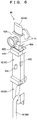
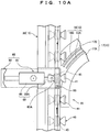
- the branch unit 60 includes the branch device 61, and an enclosure 62 supporting the branch device 61.
- the branch device 61 mainly includes a guide member 63 guiding the head portion 45 of the carrier 40, and a towing device 64 (an example of "towing portion") towing the guide member 63.
- the guide member 63 is composed of a lengthy concave member.
- a concave guide portion guiding the head portion 45 of the carrier 40 is arranged downward.
- the guide member 63 guides the carrier 40 at the concave guide portion so that the head portion 45 of the carrier 40 is covered from above.
- the concave guide portion is formed with a concave depth depending on the head portion 45 of the carrier 40.
- One end portion (end portion for accepting the carrier 40) of the guide member 63 is supported turnably with respect to the enclosure 62.
- the guide member 63 has a connecting portion 63A (see FIGS. 4A and 4B ) for connecting with an arm portion 65 of the towing device 64, on one side portion of the guide member 63.
- the towing device 64 mainly includes the arm portion 65 towing the guide member 63; a cam portion 66 driving the arm portion 65; and a motor 67 driving the cam portion 66.
- the arm portion 65 can move in the horizontal direction through cam drive by the motor 67.
- One end portion of the arm portion 65 is connected to the cam portion 66.
- the other end portion of the arm portion 65 is turnably connected to the connecting portion 63A of the guide member 63.
- the cam portion 66 can be driven by the motor 67 so as to turn.
- the cam portion 66 turns with the motor 67 to thereby move the arm portion 65 in the horizontal direction.
- the motor 67 is supported by the enclosure 62.
- the motor 67 turnably supports the cam portion 66.
- the enclosure 62 is arranged above the traveling rail 30 forming the first path 11.
- the branch device 61 switches a guide direction of the support 42 by the guide member 63, and thereby switches a conveyance direction of the carrier 40.
- the branch device 61 holds the guide member 63 in a direction coaxial to the traveling rail 30 forming the first path 11. Specifically, the branch device 61 holds the guide member 63 so that the concave guide portion of the guide member 63 and the guide groove 31 of the traveling rail 30 forming the first path 11 communicate with each other. Thereby, the head portion 45 of the support 42 of the carrier 40 guided along the guide groove 31 of the traveling rail 30 from the upstream side of the first path 11 is guided along the concave guide portion of the guide member 63. The head portion 45 of the support 42 of the carrier 40 is continuously guided to the guide groove 31 of the first path 11 (traveling rail 30) on the downstream side.
- the branch device 61 holds the guide member 63 at a predetermined angle with respect to the traveling rail 30 forming the first path 11. Specifically, the branch device 61 causes the arm portion 65 of the towing device 64 to move horizontally. The branch device 61 thereby tows the guide member 63 in a direction orthogonal to the horizontal direction, with respect to the traveling rail 30 forming the first path 11. Thereby, the other end portion (end portion for passing the carrier 40 to the upper portion guide 18) of the guide member 63 turns toward the beginning portion of the upper portion guide 18. Then, the concave guide portion of the guide member 63 and the upper portion guide 18 communicate with each other.
- the head portion 45 of the support 42 of the carrier 40 guided along the guide groove 31 of the traveling rail 30 from the upstream side of the first path 11 is guided along the concave guide portion of the guide member 63.
- the support 42 is thereby directed from the first path 11 to the upper portion guide 18 (detour path 13).
- the branch unit 60 supports and guides the head portion 45 of the support 42 of the carrier 40, by the guide member 63, and thereby switches the conveyance path of the carrier 40 from the first path 11 to the detour path 13.
- the branch unit 60 switches the guide direction of the support 42 by the guide member 63, from a direction where the first path 11 is extended (direction where the guide groove 31 of the traveling rail 30 is extended), to a direction where the upper portion guide 18 is extended.
- the branch unit 60 thereby switches the conveyance path of the carrier 40 from the first path 11 to the detour path 13.
- the branch unit 60 tows the guide member 63 guiding the support 42, by the towing device 64, and thereby switches the guide direction of the support 42 by the guide member 63.
- the branch device 61 for switching the conveyance path of the carrier 40 can direct the support 42 of the carrier 40 from the first path 11 to the detour path 13. Thereby, the carrier 40 can be caused to travel from the first path 11 toward the second path 12 while the support 42 of the carrier 40 is directed from the first path 11 to the second path 12 by the branch device 61. Accordingly, when the carrier 40 travels from the first path 11 toward the second path 12, the conveyance path of the carrier 40 can be reliably switched at the branch portion 15 without bouncing up of the carrier 40.
- the support 42 is directed from the first path 11 to the detour path 13 while the support 42 is supported by the guide member 63 having the concave guide portion.
- This configuration is, however, not limited thereto.
- the support 42 can be directed from the first path 11 to the detour path 13 (upper portion guide 18), for example, the support 42 may be directed from the first path 11 to the detour path 13 simply by pressing a side portion of the support 42, without supporting the support 42.
- the guide member 63 guides the head portion 45 of the support 42, so as to direct the support 42 from the first path 11 to the detour path 13.
- This configuration is, however, not limited thereto.
- the guide member 63 may guide the body portion 43 of the support 42.
- the guide member 63 is towed by the towing device 64 so as to switch the guide direction of the support 42 by the guide member 63.
- This configuration is, however, not limited thereto.
- a turning shaft turnably supporting the guide member 63 may be directly turned by a drive source such as a motor.
- the guide member 63 is composed of the concave member.
- the guide member 63 is, however, not limited thereto, and may be composed of two flat plates standing parallel to each other in the vertical direction, for example, as long as the support 42 can be supported and guided.
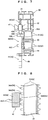
- an electric actuator 68 may mainly include an arm portion 65A towing the guide member 63; and a main body portion 69 causing the arm portion 65A to perform expansion and contraction movement.
- the electric actuator 68 may be employed as the towing device 64 of the branch device 61.
- the arm portion 65A can perform the expansion and contraction movement in the horizontal direction with respect to the main body portion 69.
- a tip end of the arm portion 65A is turnably connected to the connecting portion 63A of the guide member 63.
- the main body portion 69 is supported turnably with respect to the enclosure 62, and movably supports the arm portion 65A.
- the main body portion 69 includes a not-shown motor for moving the arm portion 65A. The motor is driven to cause the arm portion 65A to perform the expansion and contraction movement.
Applications Claiming Priority (1)
| Application Number | Priority Date | Filing Date | Title |
|---|---|---|---|
| JP2018021488A JP6996325B2 (ja) | 2018-02-09 | 2018-02-09 | 搬送設備 |
Publications (2)
| Publication Number | Publication Date |
|---|---|
| EP3524545A1 true EP3524545A1 (de) | 2019-08-14 |
| EP3524545B1 EP3524545B1 (de) | 2023-11-08 |
Family
ID=65363082
Family Applications (1)
| Application Number | Title | Priority Date | Filing Date |
|---|---|---|---|
| EP19155860.0A Active EP3524545B1 (de) | 2018-02-09 | 2019-02-07 | Förderanlage |
Country Status (4)
| Country | Link |
|---|---|
| US (1) | US10538389B2 (de) |
| EP (1) | EP3524545B1 (de) |
| JP (1) | JP6996325B2 (de) |
| CN (1) | CN110127318B (de) |
Cited By (1)
| Publication number | Priority date | Publication date | Assignee | Title |
|---|---|---|---|---|
| WO2022060226A1 (en) * | 2020-09-17 | 2022-03-24 | Urban Agrotech B.V. | Drive device for vertical elongate units suspended from a guide rail, such as growing units for plants |
Families Citing this family (2)
| Publication number | Priority date | Publication date | Assignee | Title |
|---|---|---|---|---|
| US10928133B1 (en) * | 2019-06-05 | 2021-02-23 | Pawel Malecki | Air dryer apparatus for garments with conveying mechanism |
| KR102407376B1 (ko) * | 2022-01-25 | 2022-06-10 | 길승환 | 탑승기구용 입출고 장치 |
Citations (8)
| Publication number | Priority date | Publication date | Assignee | Title |
|---|---|---|---|---|
| US5404992A (en) * | 1992-08-06 | 1995-04-11 | Rsl Logistik Gmbh & Co. | Suspension conveyor system |
| DE29511555U1 (de) * | 1995-07-18 | 1995-10-19 | Rsl Logistik Gmbh & Co | Hängefördereinrichtung |
| DE29709547U1 (de) * | 1997-06-02 | 1997-08-14 | Psb Foerderanlagen | Hängeförderanlage für auf Kleiderbügeln hängende Ware |
| DE19943141A1 (de) * | 1999-09-09 | 2001-03-15 | Wf Logistik Gmbh | Abzweigstation für eine Hängefördereinrichtung |
| DE10012524A1 (de) * | 2000-03-15 | 2001-09-20 | Wf Logistik Gmbh | Hängefördereinrichtung mit einer Umschleusungsstation |
| WO2003037760A1 (de) * | 2001-10-30 | 2003-05-08 | Khs Maschinen- Und Anlagenbau Aktiengesellschaft | Vorrichtung zum vereinzeln von getränkeflaschen mit halskragen |
| US20040107862A1 (en) * | 2002-12-06 | 2004-06-10 | Samsung Electronics Co., Ltd | Overhead transport apparatus |
| EP2117972A1 (de) | 2007-02-16 | 2009-11-18 | RSL Logistik GmbH & Co. KG | Weichenvorrichtung für eine hängefördereinrichtung |
Family Cites Families (6)
| Publication number | Priority date | Publication date | Assignee | Title |
|---|---|---|---|---|
| US3474738A (en) * | 1967-02-16 | 1969-10-28 | Fata Srl | Conveyor switch mechanism |
| US3602148A (en) * | 1969-02-05 | 1971-08-31 | Fmc Corp | Conveying apparatus |
| US3908555A (en) * | 1974-02-22 | 1975-09-30 | Hytrac Conveyors Ltd | Conveyor track switch |
| CA2186387C (en) * | 1994-04-12 | 2001-10-30 | Robby Enderlein | Suspension conveyor system |
| CA2373031A1 (en) * | 1999-05-06 | 2000-11-16 | Edward E. Ball | Conveyor system switch using tubular linear induction motor |
| DE102016105715A1 (de) * | 2016-03-29 | 2017-10-05 | Dematic Gmbh | Fördervorrichtung zur Beförderung von hängenden Gegenständen |
-
2018
- 2018-02-09 JP JP2018021488A patent/JP6996325B2/ja active Active
-
2019
- 2019-01-28 CN CN201910078030.7A patent/CN110127318B/zh active Active
- 2019-02-06 US US16/268,588 patent/US10538389B2/en active Active
- 2019-02-07 EP EP19155860.0A patent/EP3524545B1/de active Active
Patent Citations (8)
| Publication number | Priority date | Publication date | Assignee | Title |
|---|---|---|---|---|
| US5404992A (en) * | 1992-08-06 | 1995-04-11 | Rsl Logistik Gmbh & Co. | Suspension conveyor system |
| DE29511555U1 (de) * | 1995-07-18 | 1995-10-19 | Rsl Logistik Gmbh & Co | Hängefördereinrichtung |
| DE29709547U1 (de) * | 1997-06-02 | 1997-08-14 | Psb Foerderanlagen | Hängeförderanlage für auf Kleiderbügeln hängende Ware |
| DE19943141A1 (de) * | 1999-09-09 | 2001-03-15 | Wf Logistik Gmbh | Abzweigstation für eine Hängefördereinrichtung |
| DE10012524A1 (de) * | 2000-03-15 | 2001-09-20 | Wf Logistik Gmbh | Hängefördereinrichtung mit einer Umschleusungsstation |
| WO2003037760A1 (de) * | 2001-10-30 | 2003-05-08 | Khs Maschinen- Und Anlagenbau Aktiengesellschaft | Vorrichtung zum vereinzeln von getränkeflaschen mit halskragen |
| US20040107862A1 (en) * | 2002-12-06 | 2004-06-10 | Samsung Electronics Co., Ltd | Overhead transport apparatus |
| EP2117972A1 (de) | 2007-02-16 | 2009-11-18 | RSL Logistik GmbH & Co. KG | Weichenvorrichtung für eine hängefördereinrichtung |
Cited By (2)
| Publication number | Priority date | Publication date | Assignee | Title |
|---|---|---|---|---|
| WO2022060226A1 (en) * | 2020-09-17 | 2022-03-24 | Urban Agrotech B.V. | Drive device for vertical elongate units suspended from a guide rail, such as growing units for plants |
| NL1043789B1 (nl) * | 2020-09-17 | 2022-05-23 | C C Van Der Gaag Holding B V | Aandrijfinrichting voor aan een geleidingsrail opgehangen verticale langwerpige units, zoals kweekunits voor gewassen |
Also Published As
| Publication number | Publication date |
|---|---|
| EP3524545B1 (de) | 2023-11-08 |
| CN110127318A (zh) | 2019-08-16 |
| JP2019137501A (ja) | 2019-08-22 |
| JP6996325B2 (ja) | 2022-01-17 |
| US20190248589A1 (en) | 2019-08-15 |
| CN110127318B (zh) | 2021-04-27 |
| US10538389B2 (en) | 2020-01-21 |
Similar Documents
| Publication | Publication Date | Title |
|---|---|---|
| EP3524544B1 (de) | Förderanlage | |
| EP3524545B1 (de) | Förderanlage | |
| US4658947A (en) | Transfer mechanism | |
| KR101335779B1 (ko) | 벨트 컨베이어 분류기 | |
| JP4666215B2 (ja) | 物品搬送装置 | |
| DE69804641D1 (de) | Hochgeschwindigkeits-automatische-sortiervorrichtung | |
| EP3524546B1 (de) | Förderanlage | |
| US6230596B1 (en) | Method of and apparatus for conveying flat pieces of a web | |
| US3967718A (en) | Live roller conveyor | |
| JP5242931B2 (ja) | 仕分けコンベヤ | |
| SU1745117A3 (ru) | Ленточный конвейер | |
| JPH10236637A (ja) | 物品整列装置 | |
| CA1288378C (en) | Accumulating conveyor | |
| US4200186A (en) | Transfer conveyor for elongated workpieces | |
| JP3528626B2 (ja) | 搬送装置 | |
| JP2022143515A (ja) | 物品仕分け方法及び物品仕分け装置 | |
| JP2797541B2 (ja) | 結球野菜収穫機 | |
| JP2014237543A (ja) | 仕分けコンベヤ | |
| JPH07144749A (ja) | ハンガー装置使用の搬送設備 | |
| JPH09169430A (ja) | 物品搬送装置 | |
| JPH09263323A (ja) | 仕分けコンベア | |
| JPH0755731B2 (ja) | 物品の列数変更および方向転換装置 | |
| MXPA00012668A (en) | Device and method for transporting a flat article |
Legal Events
| Date | Code | Title | Description |
|---|---|---|---|
| PUAI | Public reference made under article 153(3) epc to a published international application that has entered the european phase |
Free format text: ORIGINAL CODE: 0009012 |
|
| STAA | Information on the status of an ep patent application or granted ep patent |
Free format text: STATUS: THE APPLICATION HAS BEEN PUBLISHED |
|
| AK | Designated contracting states |
Kind code of ref document: A1 Designated state(s): AL AT BE BG CH CY CZ DE DK EE ES FI FR GB GR HR HU IE IS IT LI LT LU LV MC MK MT NL NO PL PT RO RS SE SI SK SM TR |
|
| AX | Request for extension of the european patent |
Extension state: BA ME |
|
| STAA | Information on the status of an ep patent application or granted ep patent |
Free format text: STATUS: REQUEST FOR EXAMINATION WAS MADE |
|
| 17P | Request for examination filed |
Effective date: 20200214 |
|
| RBV | Designated contracting states (corrected) |
Designated state(s): AL AT BE BG CH CY CZ DE DK EE ES FI FR GB GR HR HU IE IS IT LI LT LU LV MC MK MT NL NO PL PT RO RS SE SI SK SM TR |
|
| STAA | Information on the status of an ep patent application or granted ep patent |
Free format text: STATUS: EXAMINATION IS IN PROGRESS |
|
| 17Q | First examination report despatched |
Effective date: 20220504 |
|
| GRAP | Despatch of communication of intention to grant a patent |
Free format text: ORIGINAL CODE: EPIDOSNIGR1 |
|
| STAA | Information on the status of an ep patent application or granted ep patent |
Free format text: STATUS: GRANT OF PATENT IS INTENDED |
|
| INTG | Intention to grant announced |
Effective date: 20230703 |
|
| GRAS | Grant fee paid |
Free format text: ORIGINAL CODE: EPIDOSNIGR3 |
|
| GRAA | (expected) grant |
Free format text: ORIGINAL CODE: 0009210 |
|
| STAA | Information on the status of an ep patent application or granted ep patent |
Free format text: STATUS: THE PATENT HAS BEEN GRANTED |
|
| AK | Designated contracting states |
Kind code of ref document: B1 Designated state(s): AL AT BE BG CH CY CZ DE DK EE ES FI FR GB GR HR HU IE IS IT LI LT LU LV MC MK MT NL NO PL PT RO RS SE SI SK SM TR |
|
| REG | Reference to a national code |
Ref country code: GB Ref legal event code: FG4D |
|
| REG | Reference to a national code |
Ref country code: CH Ref legal event code: EP |
|
| REG | Reference to a national code |
Ref country code: DE Ref legal event code: R096 Ref document number: 602019040905 Country of ref document: DE |
|
| REG | Reference to a national code |
Ref country code: IE Ref legal event code: FG4D |
|
| REG | Reference to a national code |
Ref country code: LT Ref legal event code: MG9D |
|
| REG | Reference to a national code |
Ref country code: NL Ref legal event code: MP Effective date: 20231108 |
|
| PG25 | Lapsed in a contracting state [announced via postgrant information from national office to epo] |
Ref country code: GR Free format text: LAPSE BECAUSE OF FAILURE TO SUBMIT A TRANSLATION OF THE DESCRIPTION OR TO PAY THE FEE WITHIN THE PRESCRIBED TIME-LIMIT Effective date: 20240209 |
|
| PG25 | Lapsed in a contracting state [announced via postgrant information from national office to epo] |
Ref country code: IS Free format text: LAPSE BECAUSE OF FAILURE TO SUBMIT A TRANSLATION OF THE DESCRIPTION OR TO PAY THE FEE WITHIN THE PRESCRIBED TIME-LIMIT Effective date: 20240308 |
|
| PG25 | Lapsed in a contracting state [announced via postgrant information from national office to epo] |
Ref country code: LT Free format text: LAPSE BECAUSE OF FAILURE TO SUBMIT A TRANSLATION OF THE DESCRIPTION OR TO PAY THE FEE WITHIN THE PRESCRIBED TIME-LIMIT Effective date: 20231108 |
|
| REG | Reference to a national code |
Ref country code: AT Ref legal event code: MK05 Ref document number: 1629447 Country of ref document: AT Kind code of ref document: T Effective date: 20231108 |
|
| PG25 | Lapsed in a contracting state [announced via postgrant information from national office to epo] |
Ref country code: NL Free format text: LAPSE BECAUSE OF FAILURE TO SUBMIT A TRANSLATION OF THE DESCRIPTION OR TO PAY THE FEE WITHIN THE PRESCRIBED TIME-LIMIT Effective date: 20231108 |