EP3524292B1 - Verpackung für eine vorgefüllte medikamentenabgabevorrichtung - Google Patents
Verpackung für eine vorgefüllte medikamentenabgabevorrichtung Download PDFInfo
- Publication number
- EP3524292B1 EP3524292B1 EP18305128.3A EP18305128A EP3524292B1 EP 3524292 B1 EP3524292 B1 EP 3524292B1 EP 18305128 A EP18305128 A EP 18305128A EP 3524292 B1 EP3524292 B1 EP 3524292B1
- Authority
- EP
- European Patent Office
- Prior art keywords
- packaging
- drug delivery
- delivery device
- needle
- shield
- Prior art date
- Legal status (The legal status is an assumption and is not a legal conclusion. Google has not performed a legal analysis and makes no representation as to the accuracy of the status listed.)
- Active
Links
- 238000012377 drug delivery Methods 0.000 title claims description 146
- 238000004806 packaging method and process Methods 0.000 title claims description 106
- LFQSCWFLJHTTHZ-UHFFFAOYSA-N Ethanol Chemical compound CCO LFQSCWFLJHTTHZ-UHFFFAOYSA-N 0.000 claims description 3
- 230000003444 anaesthetic effect Effects 0.000 claims description 3
- 238000003780 insertion Methods 0.000 claims description 2
- 230000037431 insertion Effects 0.000 claims description 2
- 230000000007 visual effect Effects 0.000 claims description 2
- 238000002347 injection Methods 0.000 description 18
- 239000007924 injection Substances 0.000 description 18
- -1 polyethylene Polymers 0.000 description 10
- 239000000463 material Substances 0.000 description 9
- 230000000717 retained effect Effects 0.000 description 8
- 206010069803 Injury associated with device Diseases 0.000 description 7
- 239000003814 drug Substances 0.000 description 7
- 229940079593 drug Drugs 0.000 description 7
- 208000027418 Wounds and injury Diseases 0.000 description 6
- 230000006378 damage Effects 0.000 description 6
- 239000003292 glue Substances 0.000 description 6
- 208000014674 injury Diseases 0.000 description 6
- 229920000642 polymer Polymers 0.000 description 6
- 239000004743 Polypropylene Substances 0.000 description 5
- 206010003246 arthritis Diseases 0.000 description 5
- 229920001155 polypropylene Polymers 0.000 description 5
- 229920000515 polycarbonate Polymers 0.000 description 4
- 239000004417 polycarbonate Substances 0.000 description 4
- 239000007779 soft material Substances 0.000 description 4
- 239000004698 Polyethylene Substances 0.000 description 3
- 229920000573 polyethylene Polymers 0.000 description 3
- 229930040373 Paraformaldehyde Natural products 0.000 description 2
- XECAHXYUAAWDEL-UHFFFAOYSA-N acrylonitrile butadiene styrene Chemical compound C=CC=C.C=CC#N.C=CC1=CC=CC=C1 XECAHXYUAAWDEL-UHFFFAOYSA-N 0.000 description 2
- 229920000122 acrylonitrile butadiene styrene Polymers 0.000 description 2
- 239000004676 acrylonitrile butadiene styrene Substances 0.000 description 2
- 238000011109 contamination Methods 0.000 description 2
- 210000003811 finger Anatomy 0.000 description 2
- 210000004247 hand Anatomy 0.000 description 2
- 230000014759 maintenance of location Effects 0.000 description 2
- 229920006324 polyoxymethylene Polymers 0.000 description 2
- 239000002699 waste material Substances 0.000 description 2
- 230000003203 everyday effect Effects 0.000 description 1
- 238000002474 experimental method Methods 0.000 description 1
- 230000036512 infertility Effects 0.000 description 1
- 239000002184 metal Substances 0.000 description 1
- 238000000034 method Methods 0.000 description 1
- 201000006417 multiple sclerosis Diseases 0.000 description 1
- 239000002985 plastic film Substances 0.000 description 1
- 229920006255 plastic film Polymers 0.000 description 1
- 229940071643 prefilled syringe Drugs 0.000 description 1
- 238000009877 rendering Methods 0.000 description 1
- 210000003813 thumb Anatomy 0.000 description 1
Images


Classifications
-
- A—HUMAN NECESSITIES
- A61—MEDICAL OR VETERINARY SCIENCE; HYGIENE
- A61M—DEVICES FOR INTRODUCING MEDIA INTO, OR ONTO, THE BODY; DEVICES FOR TRANSDUCING BODY MEDIA OR FOR TAKING MEDIA FROM THE BODY; DEVICES FOR PRODUCING OR ENDING SLEEP OR STUPOR
- A61M5/00—Devices for bringing media into the body in a subcutaneous, intra-vascular or intramuscular way; Accessories therefor, e.g. filling or cleaning devices, arm-rests
- A61M5/002—Packages specially adapted therefor, e.g. for syringes or needles, kits for diabetics
-
- A—HUMAN NECESSITIES
- A61—MEDICAL OR VETERINARY SCIENCE; HYGIENE
- A61M—DEVICES FOR INTRODUCING MEDIA INTO, OR ONTO, THE BODY; DEVICES FOR TRANSDUCING BODY MEDIA OR FOR TAKING MEDIA FROM THE BODY; DEVICES FOR PRODUCING OR ENDING SLEEP OR STUPOR
- A61M5/00—Devices for bringing media into the body in a subcutaneous, intra-vascular or intramuscular way; Accessories therefor, e.g. filling or cleaning devices, arm-rests
- A61M5/178—Syringes
- A61M5/28—Syringe ampoules or carpules, i.e. ampoules or carpules provided with a needle
-
- A—HUMAN NECESSITIES
- A61—MEDICAL OR VETERINARY SCIENCE; HYGIENE
- A61M—DEVICES FOR INTRODUCING MEDIA INTO, OR ONTO, THE BODY; DEVICES FOR TRANSDUCING BODY MEDIA OR FOR TAKING MEDIA FROM THE BODY; DEVICES FOR PRODUCING OR ENDING SLEEP OR STUPOR
- A61M5/00—Devices for bringing media into the body in a subcutaneous, intra-vascular or intramuscular way; Accessories therefor, e.g. filling or cleaning devices, arm-rests
- A61M5/178—Syringes
- A61M5/31—Details
- A61M5/32—Needles; Details of needles pertaining to their connection with syringe or hub; Accessories for bringing the needle into, or holding the needle on, the body; Devices for protection of needles
- A61M5/3202—Devices for protection of the needle before use, e.g. caps
- A61M5/3204—Needle cap remover, i.e. devices to dislodge protection cover from needle or needle hub, e.g. deshielding devices
-
- A—HUMAN NECESSITIES
- A61—MEDICAL OR VETERINARY SCIENCE; HYGIENE
- A61M—DEVICES FOR INTRODUCING MEDIA INTO, OR ONTO, THE BODY; DEVICES FOR TRANSDUCING BODY MEDIA OR FOR TAKING MEDIA FROM THE BODY; DEVICES FOR PRODUCING OR ENDING SLEEP OR STUPOR
- A61M5/00—Devices for bringing media into the body in a subcutaneous, intra-vascular or intramuscular way; Accessories therefor, e.g. filling or cleaning devices, arm-rests
- A61M5/178—Syringes
- A61M5/31—Details
- A61M5/32—Needles; Details of needles pertaining to their connection with syringe or hub; Accessories for bringing the needle into, or holding the needle on, the body; Devices for protection of needles
- A61M5/3205—Apparatus for removing or disposing of used needles or syringes, e.g. containers; Means for protection against accidental injuries from used needles
- A61M5/321—Means for protection against accidental injuries by used needles
-
- A—HUMAN NECESSITIES
- A61—MEDICAL OR VETERINARY SCIENCE; HYGIENE
- A61M—DEVICES FOR INTRODUCING MEDIA INTO, OR ONTO, THE BODY; DEVICES FOR TRANSDUCING BODY MEDIA OR FOR TAKING MEDIA FROM THE BODY; DEVICES FOR PRODUCING OR ENDING SLEEP OR STUPOR
- A61M2205/00—General characteristics of the apparatus
- A61M2205/58—Means for facilitating use, e.g. by people with impaired vision
- A61M2205/582—Means for facilitating use, e.g. by people with impaired vision by tactile feedback
-
- A—HUMAN NECESSITIES
- A61—MEDICAL OR VETERINARY SCIENCE; HYGIENE
- A61M—DEVICES FOR INTRODUCING MEDIA INTO, OR ONTO, THE BODY; DEVICES FOR TRANSDUCING BODY MEDIA OR FOR TAKING MEDIA FROM THE BODY; DEVICES FOR PRODUCING OR ENDING SLEEP OR STUPOR
- A61M2205/00—General characteristics of the apparatus
- A61M2205/58—Means for facilitating use, e.g. by people with impaired vision
- A61M2205/583—Means for facilitating use, e.g. by people with impaired vision by visual feedback
-
- A—HUMAN NECESSITIES
- A61—MEDICAL OR VETERINARY SCIENCE; HYGIENE
- A61M—DEVICES FOR INTRODUCING MEDIA INTO, OR ONTO, THE BODY; DEVICES FOR TRANSDUCING BODY MEDIA OR FOR TAKING MEDIA FROM THE BODY; DEVICES FOR PRODUCING OR ENDING SLEEP OR STUPOR
- A61M2209/00—Ancillary equipment
- A61M2209/06—Packaging for specific medical equipment
Definitions
- the present invention relates to a packaging for storing and transporting a drug delivery device, in particular a prefilled drug delivery device.
- distal end of a piece or a device is understood to be the end furthest from the hand of the user and the proximal end is understood to be the end closest to the hand of the user.
- distal direction is understood to be the direction of injection
- proximal direction is understood to be the direction opposite the direction of injection.
- a drug delivery device such as, for example, a syringe
- a drug delivery device must be handled with care before and after use due to the presence of a needle.
- syringes are typically supplied with a needle shield that covers the sharpened tip of the needle. The needle shield is removed prior to use to expose the sharpened tip of the needle and perform the injection.
- Some illnesses such as multiple sclerosis or arthritis, necessitate that a drug be injected into a patient regularly, such as every day or every week.
- the drug is available under the form of prefilled drug delivery devices, such as prefilled syringes.
- the patient is trained to self-injection and is capable to proceed to the injection of the drug by himself.
- prefilled syringes are items that need to be transported cautiously. Moreover, once used, the needle of the syringe should be protected to avoid accidental needle sticks. In addition, used prefilled syringes with needles must be discarded in specific containers intended for receiving sharp items such as needles, as well as potential contaminated medical devices.
- the present invention relates to a packaging for storing at least one drug delivery device comprising a container provided at its distal end with a distal tip
- the packaging comprising:
- the packaging of the invention is particularly intended to be used for storing a prefilled drug delivery device.
- the envelope is configured to enclose the prefilled drug delivery device before use of said drug delivery device, when the shield is received within the first holding means, and to enclose the drug delivery device after use, when at least a distal part of the needle is received within said second holding means.
- the packaging of the invention allows storing, transporting, using and discarding a prefilled drug delivery device safely.
- the drug delivery device is located at a specific location of the packaging before use and at a further specific location of the packaging after use and it may be transported safely before and after use before being discarded in an appropriate container.
- the packaging of the invention may allow storing more than one prefilled drug delivery device.
- the support may comprise more than one first holding means and/or more than one second holdings means, thereby allowing storing a plurality of prefilled drug delivery devices before and after use.
- said second holdings means are configured for further receiving at least a distal part of said distal tip.
- the second holdings means are configured for receiving the whole needle and a distal part of the distal tip, when the drug delivery device is in the after use storage configuration.
- the needle is born by the distal tip
- the needle may be born either directly by the distal tip of the drug delivery device, in which case the needle is usually a staked or an overmoulded needle, or via a needle hub mounted onto the distal tip of the drug delivery device, in which case the distal tip as such is free of any needle.
- the shield is preferably configured for covering said needle.
- the shield may be made of a rigid material.
- the shield allows therefore protecting the needle and its distal end so that accidental needle stick injuries may be avoided.
- Suitable rigid materials for forming such rigid needle shields may be selected from polyethylene, polypropylene, polycarbonate and/or combinations thereof.
- the shield may further comprise a part made of a soft material such as rubber, elastomeric polymer and/or combinations thereof.
- the shield when the distal tip is free of any needle in the before use storage configuration of said drug delivery device, the shield may then be made of a material selected from rubber, elastomeric polymers and/or combinations thereof.
- the packaging may therefore further comprise a needle hub bearing a needle, said needle hub being configured for being mounted onto a distal end of said distal tip once the shield has been removed from said distal tip.
- the first holding means and the second holding means are fixed to said support, for example in a permanent way.
- This allows the drug delivery device to be safely positioned before and after use.
- such embodiments allow using the support for removing the shield from the drug delivery device bearing the needle before use.
- prefilled drug delivery devices may be used on a regular basis by patients suffering for example from arthritis. Due to arthritis, patients' fingers hurt and are no more capable of completing precise and effort demanding gestures. These patients regularly experiment difficulties in removing the shield protecting the distal tip of the drug delivery device, as it requires to firmly handle relatively small items using both hands, like the shield on one hand, and the container of the drug delivery device on the other hand. Thanks to the packaging of the invention, the patients may use the whole support in lieu and place of the shield during the operation of removing the shield from the drug delivery device. This removal step is therefore facilitated for them.
- the first holding means comprise a first cavity configured to receive at least part of said shield and first gripping means configured to retain said shield fixed to said cavity.
- the first gripping means may be further configured to retain said shield within said cavity in a permanent way. The patient is therefore ensured that the shield will remain into the support when he removes the drug delivery device from the shield before use.
- said first gripping means comprise flexible legs capable of being snap-fitted onto said proximal end of said shield.
- said first gripping means may hold the shield onto a distal end of said shield.
- the second holding means comprise a second cavity configured to receive at least a distal part of said needle.
- the second cavity is configured to further receive at least a distal part of said distal tip.
- the second holding means may comprise second gripping means configured to retain said distal part of said distal tip within said second cavity. The needle and the distal part of the distal tip are therefore safely positioned after use, the needle being contained within said second cavity. The user and any other person who could come into contact with the device are therefore protected from accidental needle-stick injuries that could occur with the used needle.
- the second gripping means comprise flexible tongs retaining said distal part of said distal tip by friction-fit engagement.
- the second cavity may comprise an inner plug configured for embedding a distal part of the needle.
- the plug may also help, in addition to the gripping means, in securing the used drug delivery device in a stable position into the packaging after use.
- the support and the envelope form a rigid case.
- the support may comprise a distal transversal wall forming a bottom of the rigid shell and may be easily positioned on a table so that the user may hold the shell with one hand and, with the other hand :
- said first cavity has an elongated shape extending proximally from the support along a first longitudinal axis C and said second cavity has an elongated shape extending proximally from the support along a second longitudinal axis D.
- said first cavity and said second cavity may have a cylindrical shape, such as a sleeve.
- first longitudinal axis C and second longitudinal axis D are parallel to each other.
- the first cavity and the second cavity may for example extend parallel to each other from a common wall of the support.
- said first and second cavities are located on either side of a plane including said central longitudinal axis B, said first and second longitudinal axes C and D being inclined towards said central longitudinal axis B, so that a proximal end of the container of said drug delivery device is substantially located on the central longitudinal axis B when said shield is received in said first holding means in the before use storage configuration of the drug delivery device or when said distal part of said needle is received in said second holding means in the after use storage configuration of said drug delivery device.
- such an arrangement of the first and second cavities allow the drug delivery device to be held sufficiently away from a wall of the envelope when said drug delivery device is stored within the packaging, while providing a compact packaging easy to transport.
- the packaging further comprises a tactile and/or visual indicator configured to inform a user that the distal part of said needle is received in said second holding means in the after use storage configuration of said drug delivery device.
- said indicator comprises a peg capable of circulating in an open channel provided in a wall of the support and communicating with said second cavity, said peg being capable of moving from a retracted position, in which said peg is neither visible nor feelable by a user to an exposed position in which said peg may be seen and/or felt by the user, said peg being caused to move from said retracted position to said exposed position upon insertion of the distal part of said needle into said second cavity.
- the envelope comprises a film having a resealable opening.
- the packaging may therefore be opened through said opening in order to remove the drug delivery device from the packaging and therefore proceed to the injection.
- the user may reseal the opening in the film, and thereby close the packaging. He may then safely carry the packaging holding the drug delivery device with the used needle until he discards the whole packaging into an appropriate container.
- the packaging may further comprise medical items selected from anesthetic pads, alcohol swabs, sticky plasters and combinations thereof, for example located within the envelope.
- the packaging may further comprise instructions for use, for example printed onto the film forming the envelope, or printed onto a folded sheet inserted into the envelope.
- the packaging may further comprise a sheet bearing instructions for use, said sheet being folded on itself and positioned between the drug delivery device stored in said packaging in its before use storage configuration and an inner wall of the envelope, so that said sheet pops up from the packaging when a user removes the envelope from the support.
- said sheet may be folded on itself and over a piston rod of the drug delivery device.
- the sheet may be folded on itself in a concertinaed way and sandwiched between a proximal end of the plunger rod and an inner surface of a proximal wall of the envelope.
- a proximal end of the sheet may be removably attached to said inner surface of a proximal wall of the envelope and a distal end of the sheet may be removably attached to the proximal end of the plunger rod.
- the sheet may therefore be unfolded and further detached by the user as he removes the envelope form the support.
- the use of the packaging is therefore facilitated for the user as he needs not looking for the instructions for use, such instructions for use being made readily available for him.
- the prefilled drug delivery device 1 comprises a container 2 for receiving the drug 3 to be injected.
- the container 2 comprises at its distal end a distal tip 8 bearing a needle 4.
- the needle 4 is directly born by the distal tip 8.
- the container 2 is closed at its proximal end by a stopper 5.
- the needle 4 is covered by a shield 6 so as to protect it from outside contamination and so as to ensure tightness with the drug 3 contained into the container 2.
- the shield 6 further protects the user from accidental needle-stick injuries.
- the shield 6 is preferably made from a rigid material. Suitable materials for forming the shield 6 may be selected from polyethylene, polypropylene, polycarbonate and/or combinations thereof.
- the shield 6 may further comprise a part made of a soft material such as rubber, elastomeric polymer and/or combinations thereof.
- a piston rod 7 is attached to the stopper 5.
- the piston rod could be separate from the stopper 5.
- the proximal end 6a of the shield 6 is attached to the distal tip 8 of the drug delivery device 1.
- the container 2 is provided at its proximal end with a flange 9.
- the flange 9 may help the user hold the drug delivery device 1 with the index and middle fingers while his thumb is pushing on the piston rod 7.
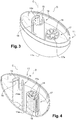
- the packaging 10 comprises a support 11 and an envelope 12.
- the envelope 12 is shaped and dimensioned so as to enclose the prefilled drug delivery device 1 before use, when the shield 6 is received within first holding means described below, as well as to enclose the drug delivery device 1 after use, when at least a distal part of the needle is received within second holding means further described below.
- the envelope 12 preferably extends proximally from the support 11 along a longitudinal axis B.
- the envelope 12 preferably comprises :
- instructions for use may be printed on the front side 22 of the envelope 12 or on a label attached to the front side of the envelope 12.
- instructions for use may be folded and inserted into the packaging such as shown on Figure 14 .
- the packaging 10 may further include medical items such as for example anesthetic pads, alcohol swabs or sticky plasters, that may be located within the envelope.
- the packaging 10 is preferably configured to be :
- the envelope may be removably attached to the support.
- the envelope forms a removable closure from the support, the envelope being configured to be:
- the envelope may be permanently fixed to the support.
- the envelope comprises an opening 13 allowing access to the drug delivery device enclosed into the envelope.
- the opening 13 is a resealable opening.
- the envelope 12 may comprise a rigid part and a flexible part.
- the envelope 12 may comprise a rigid frame 24 supporting a flexible film 25.
- the rigid frame 24 may present a U-shaped body supporting a front part 26 of the flexible film 25 closing the front side 22 of the envelope 12 and a back part 27 (see Figures 5 and 6 ) of the flexible film 25 closing the back side 23 of the envelope 12.
- the envelope may comprise a rigid shell and an opening lid attached to the rigid shell via a hinge.
- the envelope may comprise a back rigid shell and a front flexible film.
- the flexible film may be for example a plastic film, such as a polypropylene film or a polyethylene film.
- the support 11 has the shape of a rigid shell having a bottom wall 11a.
- Suitable materials for forming the rigid shell may be selected from polypropylene, polyoxymethylene, polycarbonate, acrylonitrile butadiene styrene and/or combinations thereof.
- the support 11 is configured so as to be able to stand in a substantially stable position when positioned on a horizontal surface, so that the drug delivery device 1 extends substantially vertically when it is at least partially inserted into one of the first or second holding means of the support, as will appear from the description below.
- the support 11 comprises first holding means configured for receiving at least part of the shield 6 of a prefilled drug delivery device 1, such as the one shown in Figure 1 .
- the first holding means may be configured to retain the shield of the drug delivery device when the drug delivery device is pulled out from the support.
- the first holding means are then configured to remove the shield from a drug delivery device.
- the first holding means may comprise a first cavity configured to receive the shield and first gripping means configured to retain the shield within the cavity.
- the first holding means comprise a first cavity 14a defined by an elongate casing 14 extending proximally from the support 11 along a first longitudinal axis C, the first cavity 14a being shaped and dimensioned so as to be capable of receiving the shield 6 of the prefilled drug delivery device 1, such as the one shown in Figure 1 , before use.
- the distal end of the elongate casing 14 is closed by the bottom wall 11a as shown on Figure 4 .
- the elongate casing 14 has a cylindrical shape and is fixed to the bottom wall 11a of the rigid shell 11 in a permanent way.
- the elongate casing 14 is provided at its proximal end with flexible legs 15 provided with an inner rim 16.
- the shield 6 may therefore be retained within the first cavity 14a thanks to the flexible legs 15 being snap-fitted onto said proximal end of said shield 6.
- the support 11 further comprises second holding means configured for receiving at least a distal part of the needle and optionally a distal part of the distal tip after use, preferably permanently.
- the second holding means preferably comprise a second cavity configured to receive the needle and a distal part of the distal tip and second gripping means configured to retain the needle and at least a part of the distal tip within the second cavity.
- the second holding means comprise a second cavity 17a, defined by an elongated lodging 17 extending proximally from the support 11 along a second longitudinal axis D, the second cavity 17a being shaped and dimensioned so as to be capable of receiving the used needle 4 and a distal part of the distal tip 8 of the drug delivery device 1 after use.
- the elongated lodging 17 has a cylindrical shape and is provided at its proximal end with radial flexible tongs 18 forming second gripping means for retaining the used needle and the distal tip 8 inside the elongated lodging 17 after use.
- the flexible tongs 18 may retain the distal tip 8 inside the elongated lodging 17 by friction-fit engagement or retention teeth engagement.
- the second cavity 17a comprises an inner plug 19 in which the distal end of the needle 4 may be embedded.
- Suitable materials for forming the inner plug 19 may be selected from rubber, elastomeric polymers and/or combinations thereof.
- the presence of the inner plug 19 allows maintaining the used drug delivery device 1 in a stable position once repositioned into the packaging 10.
- the first cavity 14a and the second cavity 17a are located close to each other and their longitudinal axes are parallel to each other, in the support 11.
- the packaging 10 is therefore compact.
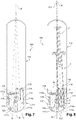
- the packaging 10 is shown before use.
- the shield of the drug delivery device 1 is retained within the first cavity 14a.
- the envelope 12 encloses the drug delivery device 1 and closes the packaging 10.
- the drug delivery device 1 extends substantially parallel to the longitudinal axis B of the packaging 10.
- the user wishes to use the drug delivery device 1, he opens the envelope 12 via the opening 13.
- the user then removes the drug delivery device 1 from the elongate casing 14, while the shield 6 remains retained within the first cavity 14a thanks to the flexible legs 15 being snap-fitted onto the proximal end of the shield 6.
- the user may pull on the drug delivery device 1 in the direction of the arrow F1 of Figure 5 with one hand, while maintaining the support 11 with the other hand (not shown).
- the step of removing the shield from the needle is therefore facilitated for people suffering from arthritis for example.
- the needle is therefore uncovered and the user may use the device in order to proceed to the injection.
- the user may approach the distal end of the used needle to the elongated lodging 17, and insert at least a distal part of the needle inside the second cavity 17a and the inner plug 19, so as to embed the distal part of the needle therein.
- the distal end of the needle is therefore protected and accidental needle stick injuries are avoided.
- the drug delivery device 1 is maintained in a stable position.
- the user may then close the packaging by covering the used drug delivery device 1 with the envelope 12 and may reseal the opening 13.
- the user may then transport the used drug delivery device 1 safely until he is able to throw the whole packaging away in a specific container.
- Suitable materials for forming the rigid case may be selected from polypropylene, polyoxymethylene, polycarbonate, acrylonitrile butadiene styrene and/or combinations thereof.
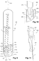
- the packaging 100 of Figures 7-9 comprises a support 111 and an envelope 112, both made of a rigid material.
- the support 111 may be closed by the envelope 112 by friction fit engagement of the support 111 in the envelope 112.
- the packaging 100 is shown in a closed configuration and therefore forms a rigid case capable of receiving a prefilled drug delivery device in a before use storage configuration and/or in an after use storage configuration.
- the support 111 comprises a first cavity 114a defined by an elongate casing 114 extending proximally from the support 111 along a first longitudinal axis C.
- the first cavity 114a is configured to receive the shield 6 of the drug delivery device 1 in a before use storage configuration of the drug delivery device 1, as shown in Figure 8 .
- the distal end of the elongate casing 114 is closed by a wall 111a of the support 111 and is therefore fixed to the support 111 in a permanent way.
- the elongate casing 114 has a cylindrical shape and is provided at its proximal end with flexible legs 115 provided with an inner rim 116.
- the drug delivery device 1 is in its before use storage configuration and is inserted in the support 111 via its shield 6 being retained within the first cavity 114a thanks to the flexible legs 115 being snap-fitted onto the proximal end 6a of the shield 6.
- the support 111 comprises a second cavity 117a defined by an elongated lodging 117 extending proximally from the support 111 along a second longitudinal axis D.
- the second cavity 117a is shaped and dimensioned so as to be capable of receiving the used needle 4 and a distal part of the distal tip 8 of the drug delivery device 1 after use.
- the elongated lodging 117 has a cylindrical shape and extends from the wall 111a of the support 111.
- the elongated lodging 117 is provided at its proximal end with radial flexible tongs 118.
- the wall 111a of the support 111 is provided with an open channel 111b allowing the distal end of the second cavity 117a to communicate with the exterior of the packaging 100.
- the second cavity 117a further includes an inner plug 119.
- the inner plug 119 is preferably made of a soft material such as rubber or an elastomeric polymer.
- the distal end of the inner plug 119 is provided with a protruding part, under the form of a peg 120.
- the inner plug 119 is configured so as to be capable of sliding within the second cavity 117a along the second longitudinal axis D, and the peg 120 is shaped and dimensioned so as to be capable of circulating within the open channel 111b.
- the peg 120 is contained within the second cavity 117a and is neither visible nor feelable by a user.
- the whole needle 4 and a distal part of the distal tip 8 of the drug delivery device 1 are received in the second cavity 117a.
- the distal part of the needle 4 is embedded in the inner plug 119.
- the flexible tongs 118 retain the distal tip 8 inside the second cavity by 117a friction-fit engagement or retention teeth engagement.
- the inner plug 119 has been pushed distally in the second cavity 117a, upon the pressure exerted by the distal tip 8 of the drug delivery device 1 coming in contact with a proximal end of the inner plug 119, thereby causing the peg 120 to move from a retracted position located within the second cavity 117a, as shown in Figures 7 or 8 , to an exposed position, at a distal end of the open channel 111b and close to the exterior of the packaging 100, where said peg 120 may be seen and/or felt by a user, as shown in Figure 9 .
- the envelope 112 extends proximally from the support 111 along a central longitudinal axis B.
- the first and second cavities (114a, 117a) are located on either side of a plane including the central longitudinal axis B.
- the first longitudinal axis C of the first cavity 114a and the second longitudinal axis D of the second cavity 117a are both inclined towards the central longitudinal axis B.
- such an arrangement of the first and second cavities (114a, 117a) allow the drug delivery device 1 to be held sufficiently away from a wall of the envelope 112 when said drug delivery device 1 is stored within the packaging 100.
- the packaging 100 is provided to a user in the before use storage configuration of the drug delivery device 1, as shown in Figure 8 .
- the drug delivery device 1 is inserted in the support 111 via its shield 6 being retained within the first cavity 114a with the flexible legs 115 snap-fitted onto a proximal end 6a of the shield 6.
- the longitudinal axis A of the drug delivery device 1 and the first longitudinal axis C of the first cavity 114a are confounded.
- a proximal end of the container of the drug delivery device 1 is substantially located on the central longitudinal axis B of the envelope 112.
- the drug delivery device 1 is as a consequence maintained at a certain distance away from the walls of the envelope 112.
- the drug delivery device 1 is maintained in a stable position thanks to its shield 6 being safely secured within the first cavity 114a.
- the user is therefore ensured that the drug delivery device 1 has not been in contact with the walls of the envelope 112 during the storage and that potential contamination of the drug delivery device has been avoided.
- the peg 120 is in a retracted position, within the second cavity 117a, where it is hidden from the view of the user.
- the user When the user is ready to proceed to the injection, he may open the rigid case formed by the support 111 and the envelope 112 by removing the envelope 112 from the support 111. The user then removes the drug delivery device 1 from the first cavity 114a, while the shield 6 remains retained within said first cavity 114a thanks to the flexible legs 115 being snap-fitted onto the proximal end 6a of the shield 6. The user may pull on the drug delivery device 1 with one hand, while maintaining the support 111 with the other hand. The step of removing the shield 6 from the needle 4 is therefore facilitated for people suffering from arthritis for example. The needle 4 is therefore uncovered and the user may use the device in order to proceed to the injection.
- the user may approach the distal end of the used needle 4 towards the second cavity 117a.
- the user inserts the needle 4 inside the second cavity 117a and inside the inner plug 119 so as to embed the needle 4 therein.
- the distal end of the distal tip 8 comes in contact with the proximal end of the inner plug 119.
- the distal end of the distal tip 8 pushes the inner plug 119 which is caused to slide distally within the second cavity 117a.
- the peg 120 is caused to move distally and enters the open channel 111b of the wall 111a of the support 111.
- the peg 120 protrudes outside the open channel 111b and becomes visible and feelable to the user.
- the peg 120 has therefore moved from its retracted position to its exposed position. In this configuration, the distal end of the needle 4 is protected and accidental needle stick injuries are avoided.
- the drug delivery device 1 is maintained in a stable position thanks to the flexible tongs 118 retaining the distal part of the distal tip 8 within the second cavity 117a.
- the user may then close the packaging 100 back by covering the used drug delivery device 1 with the envelope 112 and fit the envelope 112 on the support 111.
- the longitudinal axis A of the drug delivery device 1 and the second longitudinal axis D of the second cavity 117a are confounded and a proximal end of the container of the drug delivery device 1 is substantially located on the central longitudinal axis B of the envelope 112, thereby allowing the used drug delivery device 1 to be maintained at a certain distance away from the walls of the envelope 112.
- first and second cavities (114a; 117a) in the support 111 with their respective longitudinal axes (C, D) inclined towards the central longitudinal axis B of the envelope 112 allows the drug delivery device 1 to be held sufficiently away from a wall of the envelope 112 when said drug delivery device 1 is stored within the packaging, while rendering the packaging 100 compact and easy to transport.
- the user may therefore transport the used drug delivery device 1 in the rigid case formed by the support 111 and envelope 112 safely until he is able to throw the whole packaging 100 away in an appropriate container.
- the envelope of the packaging may further comprise information such as instructions for use.
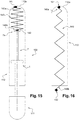
- the packaging 100 of Figures 7-9 further comprising a sheet 130, for example made of paper.
- the sheet 130 may contain information such as instructions for use.
- the sheet 130 is folded on itself and over the piston rod 7 of the drug delivery device 1, so that it is made directly available to the user when the user proceeds to the opening of the packaging 100 as shown on Figure 14 .
- the sheet 130 may be folded in a way so that said sheet 130 pops up from the packaging 100 when the user removes the envelope 112 from the support 111.
- the use of the packaging is therefore facilitated for the user, who will not waste time searching for the instructions for use.
- FIG. 15 and 16 is shown the packaging of Figures 7-9 , further comprising a sheet 140, for example made of paper.
- the sheet 140 may contain information such as instructions for use.
- the sheet 140 is folded on itself in a concertinaed way and sandwiched between a proximal end 7a of the plunger rod 7 and an inner surface of a proximal wall 112a of the envelope 112.
- a first glue dot 141 links a proximal end 140a of the folded sheet 140 to the inner surface of the proximal wall 112a.
- a second glue dot 142 links a distal end 140b of the folded sheet 140 to the proximal end 7a of the piston rod 7.
- the first glue dot 141 shows an attachment force greater than that of the second glue dot 142.
- the user may then remove completely the sheet 140 from the envelope 112 by keeping on pulling on the distal end 140b of the sheet 140, until the first glue dot 141 comes off and separates from the inner surface of the proximal wall 112a of the envelope 112.
- the use of the packaging is therefore facilitated for the user, who will not waste time searching for the instructions for use.
- the shield 206 of the drug delivery device 201 may be formed from a soft material, such as a rubber or an elastomeric polymer.
- the shield 206 covers the distal tip 208 of the drug delivery device 201 and is received within the first cavity 214a of the support 211 of the packaging 200 when the drug delivery device 201 is in its before use storage configuration.
- the shield 206 may be retained within the first cavity 214a by means of flexible legs 215 forming first gripping means.
- the packaging 200 may therefore further comprise a needle hub 220, as shown in Figure 11 .
- the needle hub 220 comprises a hub 221 bearing a needle 4 and a proximal sleeve 222 defining a conical recess 223 configured to be fitted onto the distal tip 208.
- the user when the user is ready to proceed to the injection, he may remove the drug delivery device 201 from the first cavity 214a while the shield 206 remains retained within said first cavity 214a thanks to the flexible legs 215 being snap-fitted onto the shield 206.
- the user has therefore in hands a drug delivery device 201 provided with a distal tip 208 free of any needle.
- the user may then grasp the needle hub 220 provided in the packaging 200 and mount said needle hub 220 onto the distal tip 208 by fitting the conical recess 223 onto said distal tip 208.
- the user is thereby provided with a drug delivery device 201 provided with a needle 4 and he may proceed to the injection.
- the user may simply insert the used needle into the second cavity (not shown) in the same manner as described in the above description for embodiments of Figures 2-9 , without having to remove the needle hub 220 from the distal tip 208.
- FIG. 12 With reference to Figure 12 is shown an alternative embodiment of a first cavity 314a of a support 311 of a packaging 300 of the invention in which the first gripping means retain the shield 306 of the drug delivery device (not shown) fixed to said first cavity 314a thanks to a cooperation with a distal end of said shield 306.
- the first cavity 314a is defined by a port 314 comprising flexible legs 315.
- the shield 306 is provided with a distal outer rim 306a.
- the flexible legs 315 are snap-fitted onto the distal outer rim 306a of the shield 306, thereby forming first gripping means retaining the shield 306 fixed to the cavity 314a.
- the second cavity 417a is defined by an elongated lodging 417 configured for receiving at least a distal part of the needle 4.
- the elongated lodging 417 is provided at its proximal end with flexible legs 418 provided with inner rims 418a.
- the flexible legs 418 and their inner rims 418a are made of a flexible metal allowing and are capable of being snap-fitted to the needle 4 so as to retain said needle 4 within the second cavity 417.
- the packaging of the invention allows safely storing and transporting a prefilled drug delivery device, before and after use.
Claims (17)
- Verpackung (10; 100; 200; 300; 400) zum Lagern mindestens einer Medikamentenabgabevorrichtung (1; 201), einen Behälter (2) umfassend, der an seinem distalen Ende mit einer distalen Spitze (8; 208; 408), die in einer Lagerungskonfiguration vor der Nutzung der Medikamentenabgabevorrichtung durch einen Schutz (6; 206) abgedeckt ist, wobei der Schutz (6; 206) dazu vorgesehen ist, zur Nutzungszeit von der distalen Spitze (8; 208; 408) abgenommen zu werden, und ein distales Ende der distalen Spitze (8; 208; 408) dazu vorgesehen ist, während der Nutzung der Medikamentenabgabevorrichtung eine Nadel (4) zu tragen, wobei die Verpackung umfasst:- eine Auflage (11; 111; 211; 311; 411), mindestens Folgendes umfassend:- ein erstes Haltemittel (14, 14a; 114, 114a; 214a; 314a), das in der Lagerungskonfiguration vor der Nutzung der Medikamentenabgabevorrichtung zur Aufnahme mindestens eines Teils des Schutzes (6; 206; 306) konfiguriert ist,- ein zweites Haltemittel (17, 17a; 117, 117a; 417; 417a), das in einer Lagerungskonfiguration nach der Nutzung der Medikamentenabgabevorrichtung zur Aufnahme mindestens eines Teils der Nadel (4) konfiguriert ist, wenn die Nadel durch die distale Spitze (8; 408) getragen wird,- eine Hülle (12; 112), die konfiguriert ist, um die Medikamentenabgabevorrichtung (1; 201) einzuschließen, wenn der Schutz in der Lagerungskonfiguration vor der Nutzung der Medikamentenabgabevorrichtung in dem ersten Haltemittel aufgenommen ist, und wenn der distale Teil der Nadel in der Lagerungskonfiguration nach der Nutzung der Medikamentenabgabevorrichtung in dem zweiten Haltemittel aufgenommen ist, wobei die Hülle konfiguriert ist, um durch die Auflage geschlossen zu werden.
- Verpackung (10; 100; 200; 300) nach Anspruch 1, wobei die zweiten Haltemittel konfiguriert sind, um weiter mindestens einen distalen Teil der distalen Spitze (8; 208; 408) aufzunehmen.
- Verpackung (200) nach Anspruch 1 oder 2, wobei die distale Spitze (208) in der Lagerungskonfiguration vor der Nutzung der Medikamentenabgabevorrichtung (201) frei von jeder Nadel ist, wobei die Verpackung weiter einen Nadelansatz (220) umfasst, der eine Nadel (4) trägt, wobei der Nadelansatz konfiguriert ist, um auf ein distales Ende der distalen Spitze (208) montiert zu werden, sobald der Schutz (206) von der distalen Spitze abgenommen worden ist.
- Verpackung (10; 100; 200; 300) nach einem der Ansprüche 1 bis 3, wobei die ersten Haltemittel einen ersten Hohlraum (14a; 114a, 214a; 314a) umfassen, der konfiguriert ist, um mindestens einen Teil des Schutzes (6; 206; 306) aufzunehmen, und erste Greifmittel (15, 16; 115, 116, 215; 315), die konfiguriert sind, um den Schutz (6; 206; 306), der in dem Hohlraum (14a; 114a, 214a; 314a) fixiert ist, zurückzubehalten.
- Verpackung (10; 100) nach Anspruch 4, wobei ein proximales Ende (6a) des Schutzes (6) an der distalen Spitze (8) angebracht ist, wobei die ersten Greifmittel flexible Schenkel (15; 115) umfassen, die in der Lage sind, in das proximale Ende (6a) des Schutzes (6) einzuschnappen.
- Verpackung (10; 100) nach einem der Ansprüche 1 bis 5, wobei die zweiten Haltemittel einen zweiten Hohlraum (17a; 117a) umfassen, der konfiguriert ist, um die Nadel (4) und mindestens einen distalen Teil der distalen Spitze (8) aufzunehmen, und zweite Greifmittel (18; 118), die konfiguriert sind, um die Nadel (4) und den distalen Teil der distalen Spitze (8) innerhalb des zweiten Hohlraumes (17a; 117a) zurückzubehalten.
- Verpackung (10; 100) nach Anspruch 6, wobei die zweiten Greifmittel flexible Zangen (18; 118) umfassen, die die distale Spitze (8) durch Reibschlusseingriff zurückbehalten.
- Verpackung (10; 100) nach Anspruch 6 oder 7, wobei der zweite Hohlraum (17a; 117a) weiter einen Inneneinsatz (19; 119) umfasst, der konfiguriert ist, um einen distalen Teil der Nadel (4) einzubetten.
- Verpackung (100) nach einem der Ansprüche 1 bis 8, wobei die Auflage (111) und die Hülle (112) ein starres Gehäuse bilden.
- Verpackung (10; 100) nach den Ansprüchen 4 und 6, wobei der erste Hohlraum (14a; 114a) eine längliche Form aufweist, die sich proximal von der Auflage entlang einer ersten Längsachse C erstreckt, und der zweite Hohlraum (17a; 117a) eine längliche Form aufweist, die sich proximal von der Auflage entlang einer zweiten Längsachse D erstreckt.
- Verpackung (10) nach Anspruch 10, wobei die erste Längsachse C und die zweite Längsachse D parallel zueinander sind.
- Verpackung (100) nach Anspruch 10, wobei sich die Hülle (112) proximal von der Auflage (111) entlang einer zentralen Längsachse B erstreckt, wobei sich der erste und zweite Hohlraum (114a, 117a) auf jeder Seite einer Ebene befinden, die die zentrale Längsachse B beinhaltet, wobei die erste und zweite Längsachse C und D zur zentralen Längsachse B geneigt sind, sodass sich ein proximales Ende des Behälters (2) der Medikamentenabgabevorrichtung (1) im Wesentlichen auf der zentralen Längsachse B befindet, wenn der Schutz (6) in der Lagerkonfiguration vor der Nutzung der Medikamentenabgabevorrichtung (1) in den ersten Haltemitteln (114, 114a) aufgenommen ist, oder wenn der distale Teil der Nadel (4) in der Lagerkonfiguration nach der Nutzung der Medikamentenabgabevorrichtung (1) in den zweiten Haltemitteln (117, 117a) aufgenommen ist.
- Verpackung (100) nach einem der Ansprüche 1 bis 12, weiter einen fühlbaren und/oder visuellen Anzeiger (120) umfassend, der konfiguriert ist, um einen Nutzer zu informieren, dass der distale Teil der Nadel (4) in der Lagerkonfiguration nach der Nutzung der Medikamentenabgabevorrichtung (1) in den zweiten Haltemitteln (117, 117a) aufgenommen ist.
- Verpackung (100) nach Anspruch 13, wobei der Anzeiger einen Zapfen (120) umfasst, der in der Lage ist, in einem offenen Kanal (111b), der in einer Wand (111a) der Auflage (111) bereitgestellt ist, zu zirkulieren und mit dem zweiten Hohlraum (117a) zu kommunizieren, wobei der Zapfen (120) in der Lage ist, sich von einer eingezogenen Position, in der der Zapfen durch einen Nutzer weder sichtbar, noch fühlbar ist, zu einer offengelegten Position zu bewegen, in der der Zapfen durch den Nutzer gesehen und/oder gefühlt werden kann, wobei der Zapfen (120) dazu veranlasst wird, sich beim Einführen des distalen Teils der Nadel (4) in den zweiten Hohlraum (117a) von der eingezogenen Position zu der offengelegten Position zu bewegen.
- Verpackung (10) nach einem der Ansprüche 1 bis 8, wobei die Hülle (12) einen Film umfasst, der eine wiederverschließbare Öffnung (13) aufweist.
- Verpackung (10; 100) nach einem der Ansprüche 1 bis 15, weiter medizinische Artikel umfassend, die aus Narkosekissen, Alkoholtupfern, Klebepflastern und Kombinationen daraus ausgewählt werden, die sich beispielsweise in der Hülle (12; 112) befinden.
- Verpackung (100) nach einem der Ansprüche 1 bis 16, weiter ein Blatt (130; 140) umfassend, das Instruktionen zur Nutzung trägt, wobei das Blatt zusammengefaltet ist und zwischen der in der Lagerkonfiguration vor der Nutzung gelagerten Medikamentenabgabevorrichtung (1) und einer Innenwand der Hülle (112) positioniert ist, sodass das Blatt (130; 140) aus der Verpackung (100) auftaucht, wenn ein Nutzer die Hülle (112) von der Auflage (111) abnimmt.
Priority Applications (7)
| Application Number | Priority Date | Filing Date | Title |
|---|---|---|---|
| ES18305128T ES2831362T3 (es) | 2018-02-07 | 2018-02-07 | Embalaje para un dispositivo de administración de fármaco prellenado |
| EP18305128.3A EP3524292B1 (de) | 2018-02-07 | 2018-02-07 | Verpackung für eine vorgefüllte medikamentenabgabevorrichtung |
| PCT/EP2019/052753 WO2019154796A1 (en) | 2018-02-07 | 2019-02-05 | Packaging for a prefilled drug delivery device |
| CN201980009123.2A CN111629768B (zh) | 2018-02-07 | 2019-02-05 | 用于预填充式药物递送装置的包装 |
| JP2020542759A JP7282096B2 (ja) | 2018-02-07 | 2019-02-05 | 事前充填された薬物送達デバイスのためのパッケージング |
| US16/967,585 US11376358B2 (en) | 2018-02-07 | 2019-02-05 | Packaging for a prefilled drug delivery device |
| KR1020207025340A KR102624584B1 (ko) | 2018-02-07 | 2019-02-05 | 사전 충전된 약물 전달 장치용 패키징 |
Applications Claiming Priority (1)
| Application Number | Priority Date | Filing Date | Title |
|---|---|---|---|
| EP18305128.3A EP3524292B1 (de) | 2018-02-07 | 2018-02-07 | Verpackung für eine vorgefüllte medikamentenabgabevorrichtung |
Publications (2)
| Publication Number | Publication Date |
|---|---|
| EP3524292A1 EP3524292A1 (de) | 2019-08-14 |
| EP3524292B1 true EP3524292B1 (de) | 2020-08-26 |
Family
ID=61244514
Family Applications (1)
| Application Number | Title | Priority Date | Filing Date |
|---|---|---|---|
| EP18305128.3A Active EP3524292B1 (de) | 2018-02-07 | 2018-02-07 | Verpackung für eine vorgefüllte medikamentenabgabevorrichtung |
Country Status (7)
| Country | Link |
|---|---|
| US (1) | US11376358B2 (de) |
| EP (1) | EP3524292B1 (de) |
| JP (1) | JP7282096B2 (de) |
| KR (1) | KR102624584B1 (de) |
| CN (1) | CN111629768B (de) |
| ES (1) | ES2831362T3 (de) |
| WO (1) | WO2019154796A1 (de) |
Families Citing this family (2)
| Publication number | Priority date | Publication date | Assignee | Title |
|---|---|---|---|---|
| US20230037529A1 (en) * | 2019-12-18 | 2023-02-09 | Janssen Pharmaceutica Nv | Packaging systems for drug delivery devices and packaging kits |
| WO2022242838A1 (en) * | 2021-05-18 | 2022-11-24 | Terumo Europe N.V. | Safety needle assembly |
Family Cites Families (14)
| Publication number | Priority date | Publication date | Assignee | Title |
|---|---|---|---|---|
| US4411662A (en) * | 1982-04-06 | 1983-10-25 | Baxter Travenol Laboratories, Inc. | Sterile coupling |
| ATE157268T1 (de) * | 1989-10-27 | 1997-09-15 | Automatic Springs Pty Ltd | Behälter zum aufbewahren und wegwerfen von spritzen |
| GB8926825D0 (en) * | 1989-11-28 | 1990-01-17 | Glaxo Group Ltd | Device |
| US5133454A (en) * | 1990-12-06 | 1992-07-28 | Hammer Steven G | Intravenous catheter biohazard prevention packaging device |
| US5249679A (en) * | 1992-05-06 | 1993-10-05 | Dondlinger Steven C | Medical needle disposal package |
| WO2003051423A2 (en) | 2001-12-13 | 2003-06-26 | Becton Dickinson And Company | Needle closure system removal device |
| WO2006053005A1 (en) * | 2004-11-09 | 2006-05-18 | Kaveh Khajavi | System and method for preventing wrong-site surgeries |
| US8044778B2 (en) * | 2007-07-12 | 2011-10-25 | Henry Schein, Inc. | Injection device and case with reporting ability |
| JP4928999B2 (ja) | 2007-03-19 | 2012-05-09 | テルモ株式会社 | 操作器具セット |
| US8002737B2 (en) * | 2007-10-04 | 2011-08-23 | Hyprotek, Inc. | Mixing/administration syringe devices, protective packaging and methods of protecting syringe handlers |
| JP5373916B2 (ja) * | 2008-09-18 | 2013-12-18 | ベクトン・ディキンソン・アンド・カンパニー | 連結された本体部分を備える医療用インジェクター |
| EP2574355A1 (de) * | 2011-09-27 | 2013-04-03 | Sanofi-Aventis Deutschland GmbH | Verpackung für eine Arzneimittelverabreichungsvorrichtung |
| BR112015022171B1 (pt) * | 2013-03-14 | 2023-01-03 | Fresenius Kabi Deutschland Gmbh | Sistema de embalagem farmacêutica para um fármaco sensível ao oxigênio injetável |
| EP3448454A4 (de) | 2016-04-28 | 2019-10-23 | Becton, Dickinson and Company | Nadelspeichermagazin mit statusanzeige |
-
2018
- 2018-02-07 ES ES18305128T patent/ES2831362T3/es active Active
- 2018-02-07 EP EP18305128.3A patent/EP3524292B1/de active Active
-
2019
- 2019-02-05 US US16/967,585 patent/US11376358B2/en active Active
- 2019-02-05 WO PCT/EP2019/052753 patent/WO2019154796A1/en active Application Filing
- 2019-02-05 JP JP2020542759A patent/JP7282096B2/ja active Active
- 2019-02-05 KR KR1020207025340A patent/KR102624584B1/ko active IP Right Grant
- 2019-02-05 CN CN201980009123.2A patent/CN111629768B/zh active Active
Non-Patent Citations (1)
| Title |
|---|
| None * |
Also Published As
| Publication number | Publication date |
|---|---|
| KR102624584B1 (ko) | 2024-01-15 |
| WO2019154796A1 (en) | 2019-08-15 |
| CN111629768A (zh) | 2020-09-04 |
| KR20200118114A (ko) | 2020-10-14 |
| US20210236713A1 (en) | 2021-08-05 |
| JP2021512720A (ja) | 2021-05-20 |
| ES2831362T3 (es) | 2021-06-08 |
| JP7282096B2 (ja) | 2023-05-26 |
| CN111629768B (zh) | 2022-06-28 |
| EP3524292A1 (de) | 2019-08-14 |
| US11376358B2 (en) | 2022-07-05 |
Similar Documents
| Publication | Publication Date | Title |
|---|---|---|
| US11786670B2 (en) | Pen needle removal device for a drug delivery device | |
| US5797885A (en) | Apparatus and method for recapping syringe needles | |
| US5344404A (en) | Syringe assembly having a non-resuable needle shield | |
| CA2348154C (en) | Hypodermic syringe having a selectively retractable needle | |
| US4950242A (en) | Hypodermic needle cover and assembly therewith | |
| EP0815887B1 (de) | Medizinische Einwegnadeleinrichtung | |
| US20210338927A1 (en) | Simplified and/or one-handed use of a patch injector | |
| CA3078916C (en) | Needle shield puller for drug delivery system | |
| US11376358B2 (en) | Packaging for a prefilled drug delivery device | |
| WO2007091153A1 (en) | Packaging container for a needle assembly | |
| EP2073874B1 (de) | Nadelsicherheitsvorrichtung | |
| JP3715379B2 (ja) | 医療用穿刺具 | |
| MXPA01005207A (en) | Hypodermic syringe having a selectively retractable needle |
Legal Events
| Date | Code | Title | Description |
|---|---|---|---|
| PUAI | Public reference made under article 153(3) epc to a published international application that has entered the european phase |
Free format text: ORIGINAL CODE: 0009012 |
|
| STAA | Information on the status of an ep patent application or granted ep patent |
Free format text: STATUS: THE APPLICATION HAS BEEN PUBLISHED |
|
| AK | Designated contracting states |
Kind code of ref document: A1 Designated state(s): AL AT BE BG CH CY CZ DE DK EE ES FI FR GB GR HR HU IE IS IT LI LT LU LV MC MK MT NL NO PL PT RO RS SE SI SK SM TR |
|
| AX | Request for extension of the european patent |
Extension state: BA ME |
|
| STAA | Information on the status of an ep patent application or granted ep patent |
Free format text: STATUS: REQUEST FOR EXAMINATION WAS MADE |
|
| 17P | Request for examination filed |
Effective date: 20200109 |
|
| RBV | Designated contracting states (corrected) |
Designated state(s): AL AT BE BG CH CY CZ DE DK EE ES FI FR GB GR HR HU IE IS IT LI LT LU LV MC MK MT NL NO PL PT RO RS SE SI SK SM TR |
|
| GRAP | Despatch of communication of intention to grant a patent |
Free format text: ORIGINAL CODE: EPIDOSNIGR1 |
|
| STAA | Information on the status of an ep patent application or granted ep patent |
Free format text: STATUS: GRANT OF PATENT IS INTENDED |
|
| INTG | Intention to grant announced |
Effective date: 20200609 |
|
| GRAS | Grant fee paid |
Free format text: ORIGINAL CODE: EPIDOSNIGR3 |
|
| GRAA | (expected) grant |
Free format text: ORIGINAL CODE: 0009210 |
|
| STAA | Information on the status of an ep patent application or granted ep patent |
Free format text: STATUS: THE PATENT HAS BEEN GRANTED |
|
| AK | Designated contracting states |
Kind code of ref document: B1 Designated state(s): AL AT BE BG CH CY CZ DE DK EE ES FI FR GB GR HR HU IE IS IT LI LT LU LV MC MK MT NL NO PL PT RO RS SE SI SK SM TR |
|
| REG | Reference to a national code |
Ref country code: GB Ref legal event code: FG4D |
|
| REG | Reference to a national code |
Ref country code: CH Ref legal event code: EP |
|
| REG | Reference to a national code |
Ref country code: AT Ref legal event code: REF Ref document number: 1305746 Country of ref document: AT Kind code of ref document: T Effective date: 20200915 Ref country code: CH Ref legal event code: NV Representative=s name: CABINET GERMAIN AND MAUREAU, CH |
|
| REG | Reference to a national code |
Ref country code: IE Ref legal event code: FG4D |
|
| REG | Reference to a national code |
Ref country code: DE Ref legal event code: R096 Ref document number: 602018007298 Country of ref document: DE |
|
| REG | Reference to a national code |
Ref country code: LT Ref legal event code: MG4D |
|
| PG25 | Lapsed in a contracting state [announced via postgrant information from national office to epo] |
Ref country code: HR Free format text: LAPSE BECAUSE OF FAILURE TO SUBMIT A TRANSLATION OF THE DESCRIPTION OR TO PAY THE FEE WITHIN THE PRESCRIBED TIME-LIMIT Effective date: 20200826 Ref country code: LT Free format text: LAPSE BECAUSE OF FAILURE TO SUBMIT A TRANSLATION OF THE DESCRIPTION OR TO PAY THE FEE WITHIN THE PRESCRIBED TIME-LIMIT Effective date: 20200826 Ref country code: BG Free format text: LAPSE BECAUSE OF FAILURE TO SUBMIT A TRANSLATION OF THE DESCRIPTION OR TO PAY THE FEE WITHIN THE PRESCRIBED TIME-LIMIT Effective date: 20201126 Ref country code: SE Free format text: LAPSE BECAUSE OF FAILURE TO SUBMIT A TRANSLATION OF THE DESCRIPTION OR TO PAY THE FEE WITHIN THE PRESCRIBED TIME-LIMIT Effective date: 20200826 Ref country code: PT Free format text: LAPSE BECAUSE OF FAILURE TO SUBMIT A TRANSLATION OF THE DESCRIPTION OR TO PAY THE FEE WITHIN THE PRESCRIBED TIME-LIMIT Effective date: 20201228 Ref country code: GR Free format text: LAPSE BECAUSE OF FAILURE TO SUBMIT A TRANSLATION OF THE DESCRIPTION OR TO PAY THE FEE WITHIN THE PRESCRIBED TIME-LIMIT Effective date: 20201127 Ref country code: NO Free format text: LAPSE BECAUSE OF FAILURE TO SUBMIT A TRANSLATION OF THE DESCRIPTION OR TO PAY THE FEE WITHIN THE PRESCRIBED TIME-LIMIT Effective date: 20201126 Ref country code: FI Free format text: LAPSE BECAUSE OF FAILURE TO SUBMIT A TRANSLATION OF THE DESCRIPTION OR TO PAY THE FEE WITHIN THE PRESCRIBED TIME-LIMIT Effective date: 20200826 |
|
| REG | Reference to a national code |
Ref country code: NL Ref legal event code: MP Effective date: 20200826 |
|
| REG | Reference to a national code |
Ref country code: AT Ref legal event code: MK05 Ref document number: 1305746 Country of ref document: AT Kind code of ref document: T Effective date: 20200826 |
|
| PG25 | Lapsed in a contracting state [announced via postgrant information from national office to epo] |
Ref country code: IS Free format text: LAPSE BECAUSE OF FAILURE TO SUBMIT A TRANSLATION OF THE DESCRIPTION OR TO PAY THE FEE WITHIN THE PRESCRIBED TIME-LIMIT Effective date: 20201226 Ref country code: RS Free format text: LAPSE BECAUSE OF FAILURE TO SUBMIT A TRANSLATION OF THE DESCRIPTION OR TO PAY THE FEE WITHIN THE PRESCRIBED TIME-LIMIT Effective date: 20200826 Ref country code: PL Free format text: LAPSE BECAUSE OF FAILURE TO SUBMIT A TRANSLATION OF THE DESCRIPTION OR TO PAY THE FEE WITHIN THE PRESCRIBED TIME-LIMIT Effective date: 20200826 Ref country code: LV Free format text: LAPSE BECAUSE OF FAILURE TO SUBMIT A TRANSLATION OF THE DESCRIPTION OR TO PAY THE FEE WITHIN THE PRESCRIBED TIME-LIMIT Effective date: 20200826 Ref country code: NL Free format text: LAPSE BECAUSE OF FAILURE TO SUBMIT A TRANSLATION OF THE DESCRIPTION OR TO PAY THE FEE WITHIN THE PRESCRIBED TIME-LIMIT Effective date: 20200826 |
|
| PG25 | Lapsed in a contracting state [announced via postgrant information from national office to epo] |
Ref country code: SM Free format text: LAPSE BECAUSE OF FAILURE TO SUBMIT A TRANSLATION OF THE DESCRIPTION OR TO PAY THE FEE WITHIN THE PRESCRIBED TIME-LIMIT Effective date: 20200826 Ref country code: RO Free format text: LAPSE BECAUSE OF FAILURE TO SUBMIT A TRANSLATION OF THE DESCRIPTION OR TO PAY THE FEE WITHIN THE PRESCRIBED TIME-LIMIT Effective date: 20200826 Ref country code: CZ Free format text: LAPSE BECAUSE OF FAILURE TO SUBMIT A TRANSLATION OF THE DESCRIPTION OR TO PAY THE FEE WITHIN THE PRESCRIBED TIME-LIMIT Effective date: 20200826 Ref country code: DK Free format text: LAPSE BECAUSE OF FAILURE TO SUBMIT A TRANSLATION OF THE DESCRIPTION OR TO PAY THE FEE WITHIN THE PRESCRIBED TIME-LIMIT Effective date: 20200826 Ref country code: EE Free format text: LAPSE BECAUSE OF FAILURE TO SUBMIT A TRANSLATION OF THE DESCRIPTION OR TO PAY THE FEE WITHIN THE PRESCRIBED TIME-LIMIT Effective date: 20200826 |
|
| REG | Reference to a national code |
Ref country code: DE Ref legal event code: R097 Ref document number: 602018007298 Country of ref document: DE |
|
| PG25 | Lapsed in a contracting state [announced via postgrant information from national office to epo] |
Ref country code: AL Free format text: LAPSE BECAUSE OF FAILURE TO SUBMIT A TRANSLATION OF THE DESCRIPTION OR TO PAY THE FEE WITHIN THE PRESCRIBED TIME-LIMIT Effective date: 20200826 Ref country code: AT Free format text: LAPSE BECAUSE OF FAILURE TO SUBMIT A TRANSLATION OF THE DESCRIPTION OR TO PAY THE FEE WITHIN THE PRESCRIBED TIME-LIMIT Effective date: 20200826 |
|
| REG | Reference to a national code |
Ref country code: ES Ref legal event code: FG2A Ref document number: 2831362 Country of ref document: ES Kind code of ref document: T3 Effective date: 20210608 |
|
| PG25 | Lapsed in a contracting state [announced via postgrant information from national office to epo] |
Ref country code: SK Free format text: LAPSE BECAUSE OF FAILURE TO SUBMIT A TRANSLATION OF THE DESCRIPTION OR TO PAY THE FEE WITHIN THE PRESCRIBED TIME-LIMIT Effective date: 20200826 |
|
| PLBE | No opposition filed within time limit |
Free format text: ORIGINAL CODE: 0009261 |
|
| STAA | Information on the status of an ep patent application or granted ep patent |
Free format text: STATUS: NO OPPOSITION FILED WITHIN TIME LIMIT |
|
| 26N | No opposition filed |
Effective date: 20210527 |
|
| PG25 | Lapsed in a contracting state [announced via postgrant information from national office to epo] |
Ref country code: SI Free format text: LAPSE BECAUSE OF FAILURE TO SUBMIT A TRANSLATION OF THE DESCRIPTION OR TO PAY THE FEE WITHIN THE PRESCRIBED TIME-LIMIT Effective date: 20200826 |
|
| PG25 | Lapsed in a contracting state [announced via postgrant information from national office to epo] |
Ref country code: MC Free format text: LAPSE BECAUSE OF FAILURE TO SUBMIT A TRANSLATION OF THE DESCRIPTION OR TO PAY THE FEE WITHIN THE PRESCRIBED TIME-LIMIT Effective date: 20200826 |
|
| REG | Reference to a national code |
Ref country code: BE Ref legal event code: MM Effective date: 20210228 |
|
| PG25 | Lapsed in a contracting state [announced via postgrant information from national office to epo] |
Ref country code: LU Free format text: LAPSE BECAUSE OF NON-PAYMENT OF DUE FEES Effective date: 20210207 |
|
| PG25 | Lapsed in a contracting state [announced via postgrant information from national office to epo] |
Ref country code: IE Free format text: LAPSE BECAUSE OF NON-PAYMENT OF DUE FEES Effective date: 20210207 |
|
| PG25 | Lapsed in a contracting state [announced via postgrant information from national office to epo] |
Ref country code: BE Free format text: LAPSE BECAUSE OF NON-PAYMENT OF DUE FEES Effective date: 20210228 |
|
| PGFP | Annual fee paid to national office [announced via postgrant information from national office to epo] |
Ref country code: FR Payment date: 20230119 Year of fee payment: 6 Ref country code: ES Payment date: 20230301 Year of fee payment: 6 Ref country code: CH Payment date: 20230307 Year of fee payment: 6 |
|
| PGFP | Annual fee paid to national office [announced via postgrant information from national office to epo] |
Ref country code: IT Payment date: 20230120 Year of fee payment: 6 Ref country code: GB Payment date: 20230121 Year of fee payment: 6 Ref country code: DE Payment date: 20230119 Year of fee payment: 6 |
|
| PG25 | Lapsed in a contracting state [announced via postgrant information from national office to epo] |
Ref country code: CY Free format text: LAPSE BECAUSE OF FAILURE TO SUBMIT A TRANSLATION OF THE DESCRIPTION OR TO PAY THE FEE WITHIN THE PRESCRIBED TIME-LIMIT Effective date: 20200826 |
|
| PG25 | Lapsed in a contracting state [announced via postgrant information from national office to epo] |
Ref country code: HU Free format text: LAPSE BECAUSE OF FAILURE TO SUBMIT A TRANSLATION OF THE DESCRIPTION OR TO PAY THE FEE WITHIN THE PRESCRIBED TIME-LIMIT; INVALID AB INITIO Effective date: 20180207 |
|
| PGFP | Annual fee paid to national office [announced via postgrant information from national office to epo] |
Ref country code: ES Payment date: 20240301 Year of fee payment: 7 |