EP3523839B1 - Energiezellenhaltevorrichtung für ein kraftfahrzeug - Google Patents
Energiezellenhaltevorrichtung für ein kraftfahrzeug Download PDFInfo
- Publication number
- EP3523839B1 EP3523839B1 EP17767769.7A EP17767769A EP3523839B1 EP 3523839 B1 EP3523839 B1 EP 3523839B1 EP 17767769 A EP17767769 A EP 17767769A EP 3523839 B1 EP3523839 B1 EP 3523839B1
- Authority
- EP
- European Patent Office
- Prior art keywords
- cell
- energy cell
- contact
- energy
- overhang
- Prior art date
- Legal status (The legal status is an assumption and is not a legal conclusion. Google has not performed a legal analysis and makes no representation as to the accuracy of the status listed.)
- Active
Links
Images


Classifications
-
- H—ELECTRICITY
- H01—ELECTRIC ELEMENTS
- H01M—PROCESSES OR MEANS, e.g. BATTERIES, FOR THE DIRECT CONVERSION OF CHEMICAL ENERGY INTO ELECTRICAL ENERGY
- H01M10/00—Secondary cells; Manufacture thereof
- H01M10/60—Heating or cooling; Temperature control
- H01M10/61—Types of temperature control
- H01M10/613—Cooling or keeping cold
-
- H—ELECTRICITY
- H01—ELECTRIC ELEMENTS
- H01M—PROCESSES OR MEANS, e.g. BATTERIES, FOR THE DIRECT CONVERSION OF CHEMICAL ENERGY INTO ELECTRICAL ENERGY
- H01M50/00—Constructional details or processes of manufacture of the non-active parts of electrochemical cells other than fuel cells, e.g. hybrid cells
- H01M50/10—Primary casings; Jackets or wrappings
- H01M50/102—Primary casings; Jackets or wrappings characterised by their shape or physical structure
- H01M50/107—Primary casings; Jackets or wrappings characterised by their shape or physical structure having curved cross-section, e.g. round or elliptic
-
- B—PERFORMING OPERATIONS; TRANSPORTING
- B60—VEHICLES IN GENERAL
- B60K—ARRANGEMENT OR MOUNTING OF PROPULSION UNITS OR OF TRANSMISSIONS IN VEHICLES; ARRANGEMENT OR MOUNTING OF PLURAL DIVERSE PRIME-MOVERS IN VEHICLES; AUXILIARY DRIVES FOR VEHICLES; INSTRUMENTATION OR DASHBOARDS FOR VEHICLES; ARRANGEMENTS IN CONNECTION WITH COOLING, AIR INTAKE, GAS EXHAUST OR FUEL SUPPLY OF PROPULSION UNITS IN VEHICLES
- B60K6/00—Arrangement or mounting of plural diverse prime-movers for mutual or common propulsion, e.g. hybrid propulsion systems comprising electric motors and internal combustion engines
- B60K6/20—Arrangement or mounting of plural diverse prime-movers for mutual or common propulsion, e.g. hybrid propulsion systems comprising electric motors and internal combustion engines the prime-movers consisting of electric motors and internal combustion engines, e.g. HEVs
- B60K6/22—Arrangement or mounting of plural diverse prime-movers for mutual or common propulsion, e.g. hybrid propulsion systems comprising electric motors and internal combustion engines the prime-movers consisting of electric motors and internal combustion engines, e.g. HEVs characterised by apparatus, components or means specially adapted for HEVs
- B60K6/28—Arrangement or mounting of plural diverse prime-movers for mutual or common propulsion, e.g. hybrid propulsion systems comprising electric motors and internal combustion engines the prime-movers consisting of electric motors and internal combustion engines, e.g. HEVs characterised by apparatus, components or means specially adapted for HEVs characterised by the electric energy storing means, e.g. batteries or capacitors
-
- B—PERFORMING OPERATIONS; TRANSPORTING
- B60—VEHICLES IN GENERAL
- B60L—PROPULSION OF ELECTRICALLY-PROPELLED VEHICLES; SUPPLYING ELECTRIC POWER FOR AUXILIARY EQUIPMENT OF ELECTRICALLY-PROPELLED VEHICLES; ELECTRODYNAMIC BRAKE SYSTEMS FOR VEHICLES IN GENERAL; MAGNETIC SUSPENSION OR LEVITATION FOR VEHICLES; MONITORING OPERATING VARIABLES OF ELECTRICALLY-PROPELLED VEHICLES; ELECTRIC SAFETY DEVICES FOR ELECTRICALLY-PROPELLED VEHICLES
- B60L50/00—Electric propulsion with power supplied within the vehicle
- B60L50/50—Electric propulsion with power supplied within the vehicle using propulsion power supplied by batteries or fuel cells
- B60L50/60—Electric propulsion with power supplied within the vehicle using propulsion power supplied by batteries or fuel cells using power supplied by batteries
- B60L50/64—Constructional details of batteries specially adapted for electric vehicles
-
- B—PERFORMING OPERATIONS; TRANSPORTING
- B60—VEHICLES IN GENERAL
- B60L—PROPULSION OF ELECTRICALLY-PROPELLED VEHICLES; SUPPLYING ELECTRIC POWER FOR AUXILIARY EQUIPMENT OF ELECTRICALLY-PROPELLED VEHICLES; ELECTRODYNAMIC BRAKE SYSTEMS FOR VEHICLES IN GENERAL; MAGNETIC SUSPENSION OR LEVITATION FOR VEHICLES; MONITORING OPERATING VARIABLES OF ELECTRICALLY-PROPELLED VEHICLES; ELECTRIC SAFETY DEVICES FOR ELECTRICALLY-PROPELLED VEHICLES
- B60L50/00—Electric propulsion with power supplied within the vehicle
- B60L50/50—Electric propulsion with power supplied within the vehicle using propulsion power supplied by batteries or fuel cells
- B60L50/60—Electric propulsion with power supplied within the vehicle using propulsion power supplied by batteries or fuel cells using power supplied by batteries
- B60L50/66—Arrangements of batteries
-
- H—ELECTRICITY
- H01—ELECTRIC ELEMENTS
- H01M—PROCESSES OR MEANS, e.g. BATTERIES, FOR THE DIRECT CONVERSION OF CHEMICAL ENERGY INTO ELECTRICAL ENERGY
- H01M10/00—Secondary cells; Manufacture thereof
- H01M10/60—Heating or cooling; Temperature control
- H01M10/65—Means for temperature control structurally associated with the cells
- H01M10/655—Solid structures for heat exchange or heat conduction
- H01M10/6556—Solid parts with flow channel passages or pipes for heat exchange
- H01M10/6557—Solid parts with flow channel passages or pipes for heat exchange arranged between the cells
-
- H—ELECTRICITY
- H01—ELECTRIC ELEMENTS
- H01M—PROCESSES OR MEANS, e.g. BATTERIES, FOR THE DIRECT CONVERSION OF CHEMICAL ENERGY INTO ELECTRICAL ENERGY
- H01M50/00—Constructional details or processes of manufacture of the non-active parts of electrochemical cells other than fuel cells, e.g. hybrid cells
- H01M50/20—Mountings; Secondary casings or frames; Racks, modules or packs; Suspension devices; Shock absorbers; Transport or carrying devices; Holders
- H01M50/249—Mountings; Secondary casings or frames; Racks, modules or packs; Suspension devices; Shock absorbers; Transport or carrying devices; Holders specially adapted for aircraft or vehicles, e.g. cars or trains
-
- H—ELECTRICITY
- H01—ELECTRIC ELEMENTS
- H01M—PROCESSES OR MEANS, e.g. BATTERIES, FOR THE DIRECT CONVERSION OF CHEMICAL ENERGY INTO ELECTRICAL ENERGY
- H01M50/00—Constructional details or processes of manufacture of the non-active parts of electrochemical cells other than fuel cells, e.g. hybrid cells
- H01M50/20—Mountings; Secondary casings or frames; Racks, modules or packs; Suspension devices; Shock absorbers; Transport or carrying devices; Holders
- H01M50/262—Mountings; Secondary casings or frames; Racks, modules or packs; Suspension devices; Shock absorbers; Transport or carrying devices; Holders with fastening means, e.g. locks
-
- H—ELECTRICITY
- H01—ELECTRIC ELEMENTS
- H01M—PROCESSES OR MEANS, e.g. BATTERIES, FOR THE DIRECT CONVERSION OF CHEMICAL ENERGY INTO ELECTRICAL ENERGY
- H01M2220/00—Batteries for particular applications
- H01M2220/20—Batteries in motive systems, e.g. vehicle, ship, plane
-
- Y—GENERAL TAGGING OF NEW TECHNOLOGICAL DEVELOPMENTS; GENERAL TAGGING OF CROSS-SECTIONAL TECHNOLOGIES SPANNING OVER SEVERAL SECTIONS OF THE IPC; TECHNICAL SUBJECTS COVERED BY FORMER USPC CROSS-REFERENCE ART COLLECTIONS [XRACs] AND DIGESTS
- Y02—TECHNOLOGIES OR APPLICATIONS FOR MITIGATION OR ADAPTATION AGAINST CLIMATE CHANGE
- Y02E—REDUCTION OF GREENHOUSE GAS [GHG] EMISSIONS, RELATED TO ENERGY GENERATION, TRANSMISSION OR DISTRIBUTION
- Y02E60/00—Enabling technologies; Technologies with a potential or indirect contribution to GHG emissions mitigation
- Y02E60/10—Energy storage using batteries
-
- Y—GENERAL TAGGING OF NEW TECHNOLOGICAL DEVELOPMENTS; GENERAL TAGGING OF CROSS-SECTIONAL TECHNOLOGIES SPANNING OVER SEVERAL SECTIONS OF THE IPC; TECHNICAL SUBJECTS COVERED BY FORMER USPC CROSS-REFERENCE ART COLLECTIONS [XRACs] AND DIGESTS
- Y02—TECHNOLOGIES OR APPLICATIONS FOR MITIGATION OR ADAPTATION AGAINST CLIMATE CHANGE
- Y02T—CLIMATE CHANGE MITIGATION TECHNOLOGIES RELATED TO TRANSPORTATION
- Y02T10/00—Road transport of goods or passengers
- Y02T10/60—Other road transportation technologies with climate change mitigation effect
- Y02T10/70—Energy storage systems for electromobility, e.g. batteries
Definitions
- the present invention relates to power cell modules for motor vehicles.
- the DE 10 2014 216811 A1 describes a battery module system comprising a housing for accommodating at least two battery modules, the housing having connecting elements on an inside for accommodating connecting elements of the battery modules in order to fix the battery modules in the housing, the battery modules each having an end plate on which the connecting elements of the battery modules are arranged are.
- the U.S. 2010/0 105 239 A1 and the CN 104 253 289 A each describe a battery connection device for connecting two batteries to one another in the longitudinal direction.
- the respective connecting device has a connecting plate which either has a contacting device or into which a contacting device can be inserted.
- the battery unit having a plurality of individual battery cells.
- the individual battery cells are arranged in a housing and can have the contacting poles on one side of the individual battery cells.
- One aspect of the present invention relates to a cell module structure for a motor vehicle, the cell module structure having at least one energy cell and an energy cell holding device, the energy cell holding device comprising: a contact plate which has at least one recess and at least one overhang; wherein the recess and the overhang are designed to fix the energy cell to the contact plate via a lateral surface of the energy cell in a form-fitting and/or force-fitting and/or material-fitting manner; and wherein the recess and the overhang are designed to contact at least one electrical connection of the energy cell via the lateral surface of the energy cell.
- the energy cell has a contact on an end face of the energy cell as a first electrical contact and a contact on a lateral surface as a second electrical contact, the second electrical contact being arranged within a half-side area and also the first within the half-side area electrical contact is arranged.
- the first and the second electrical contact for example, the negative and the positive pole of the energy cell.
- This arrangement advantageously enables a separation between the electrical contacting of the energy cell in one half-side area of the energy cell and the cooling of the energy cell in another half-side area of the energy cell.
- the present invention advantageously makes it possible to provide a method for contacting round battery cells with simultaneous module sealing.
- a metallic, electrically conductive plate can be provided which, for example, has a has an overhang produced by punching at the edge of a round opening or opening adapted to the geometry of the cylindrical energy cell.
- the overhang improves the retention and electrical contacting of the power cell since the length or area of contact, i.e. the contact or holding surface, with the power cell is increased.
- the plate is guided over the cylindrical lateral surface of the cell and fixed there in the contacting process.
- this contact can be made on the cylindrical lateral surface in the same upper area of the cell which also has a cover contact on the end face. This advantageously means that the lower area of the cell does not require any electrical contacting or a mechanical fastening connection, the entire installation space is available for cooling, i.e. a coolant can flow completely around the cell from one half side.
- the fixation takes place, for example, by means of positive and non-positive connection methods.
- This can be a pressing process that stamps the overhang in a positive and non-positive manner on the lateral surface of the energy cell.
- gluing, soldering or welding processes are to be preferred, since these processes enable a material connection that is even tight against liquid media - such as a cooling medium.
- the outer surface of the cell and the lower side of the contact plate--for example the side facing the coolant-- are provided with a coating after the fixation, which prevents electrical conductivity and at the same time protects the exposed materials against corrosion.
- the energy cell is placed in a container containing a thermally conductive medium with the contacts at the top and the lower, advantageously freely accessible lateral surface at the bottom.
- the thermal contact surface of the energy cell is very large due to this solution or this contact arrangement, for example over 80% of the installation space is freely accessible for the coolant, while at the same time no further seal has to be introduced to isolate the positive and negative contacts.
- a one-sided contacting of both battery poles provided.
- only a maximum of one half of the battery cell is used for the electrical contact and the mechanical fixation. This results in an immense cooling possibility, since the half-side that is not used can be completely surrounded by air.
- a tight, non-positive and form-fitting or material-fitting connection is provided around the cylindrical lateral surface in order to separate the contacting and locking of the battery cell from the cooling and to prevent coolant, for example, from entering the area of the electrical contacting .
- a mechanical connection is provided between the contact plate and the envelope surface of the power cell for the entire full circle of the circular interface between the power cell and the contact plate.
- an opening adapted to the energy cell is created in a contact plate, e.g., by punching.
- an overhang is provided, which protrudes beyond the contact plate in the direction of the positive pole, for example, and enables non-positive or material-to-material contacting, for example by means of laser welding, without damaging the energy cell.
- the two battery contacts are sealed against the cooling medium guaranteed by a form-fitting and/or material-to-substance contact.
- An advantageous embodiment of the present invention provides that the recess and the overhang are designed to fix the energy cell with the contact plate over the lateral surface of the energy cell in a form-fitting and/or non-positive and/or material-locking manner around the lateral surface.
- the cooling of the battery cell can advantageously take place on the opposite side to the locking and contacting.
- the recess and/or the overhang are designed to fix the energy cell in a form-fitting and force-fitting manner by means of a pressing process. This advantageously enables the battery cell holding device to be produced inexpensively.
- the recess and/or the overhang are designed to fix the energy cell in a material-locking manner by means of an adhesive, soldering or welding process. This advantageously makes it possible to provide a tight, materially bonded connection and to achieve a separation of areas for cooling and areas for contacting and locking.
- the recess and the overhang are designed for the lateral surface of the energy cell inside to contact a half-side area of the energy cell and, within the half-side area, to also carry out a contact on the end face of the energy cell.
- the energy cell can be contacted within one--ie one and the same--half-side area of the energy cell.
- the contact plate also has an insulating layer which is designed to protect the energy cell holding device against corrosion.
- the energy cell has, for example, a cylindrical shape or a round cell shape.
- a lateral surface of the energy cell is designed to be fixed with a contact plate of the energy cell holding device in a form-fitting and/or force-fitting and/or material-fitting manner.
- the vehicle is, for example, a motor vehicle or a hybrid motor vehicle, such as a car, a bus or a truck, or a rail vehicle, a ship, or an aircraft, such as a helicopter or airplane, or a moped, a scooter, a Trade a motorcycle, a pedelec, an electric bicycle or an eBike.
- a motor vehicle or a hybrid motor vehicle such as a car, a bus or a truck, or a rail vehicle, a ship, or an aircraft, such as a helicopter or airplane, or a moped, a scooter, a Trade a motorcycle, a pedelec, an electric bicycle or an eBike.
- the energy cell holding device can also be used for stationary energy stores.
- overhang includes an addition of material, such as a bulge or bulge.
- the overhang can also “remain” when the recess in the contact plate is punched out, for example, or can be formed by the punching process.
- energy cell or “battery cell” as used by the present invention includes an energy store for electrical energy, in particular the term includes electrochemical energy stores, which can be differentiated into primary and secondary cells.
- shell as used by the present invention includes, for example, a surface or a surface strip on the outside of the energy cell, which for example, has a cylindrical shape or a round cell shape.
- face includes, for example, a base of the cylindrical shape of the power cell.
- the 1 shows a schematic representation of a battery cell contact to explain the present invention.
- the battery cell 5 or energy cell 5 is contacted, for example, by cover and base contacting from above and below on the two end faces or base surfaces of the round cell.
- Lateral fixation or mechanical locking on the lateral surface of the energy cell 5 can take place at the points or surfaces of the energy cell 5 indicated by the arrow.
- Cylindrical battery cells - for example lithium-ion batteries - are typically contacted at the positive pole (cathode) on the top and at the negative pole (anode) on the bottom of the cells - the top and bottom of the cylinder serve as contacts.
- thermal contact can be established, for example, via the side walls of the cylinder of the round cell.
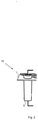
- the figure 2 shows a schematic representation of an energy cell holding device with a battery cell contact according to an embodiment of the present invention.
- a cover contacting of the battery cell or the energy cell 5 takes place, for example, as shown from above, with the positive pole of the battery being attached to the end face of the energy cell 5, for example, as indicated in the drawing.
- Contact is made via the outer casing of the energy cell 5 with the aid of the contact plate 1, which has at least one recess 4-n and at least one overhang 2-n, where n indicates the number of the energy cells 5 in the contact plate 1.
- the contact plate 1 can have a plurality of recesses 4-n and overhangs 2-n.
- the negative pole of the energy cell 5 is electrically connected, for example.
- the energy cell holding device 10 advantageously enables electrical contacting of battery cells with simultaneous, i.e. direct, cooling of the cell jacket surfaces with coolant without the use of rubber seals or similar complex characteristics with critical tolerances.
- the contact plate 1 of the energy cell holding device 10 enables several energy cells 5 to be electrically connected to form a module, also referred to as a “pack” in individual cases.
- the energy cell holding device 10 enables a block structure and a modular structure of the energy cells 5 to be achieved.
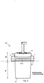
- the figure 3 shows a schematic representation of an energy cell holding device with a battery cell contact according to an embodiment of the present invention.
- the contact plate 1 has at least one overhang 2-n, which increases the contact or connection surface with the lateral surface of the energy cell 5 and thereby improves the mechanical locking of the energy cell 5 in the energy cell holding device 10 and/or the electrical contacting of the energy cell 5 with the contact plate 1 .
- the energy cell 5 can be divided into a first or upper half-side area B and a second or lower half-side area A.
- the subdivision of the half-side areas A, B can be carried out in any ratio.
- the half-side area A is advantageously larger, since this increases the cooling capacity of the cooling system. This advantageously allows, for example to minimize the temperature change caused during operation of the energy cells 5 by means of improved cooling or to keep the energy cells 5 in a predetermined temperature range even in the case of unfavorable climatic ambient temperatures.
- the electrical contacting of the energy cell 5 takes place on the one hand through the cover contact provided on the front side in the half-side area B and on the other hand also in the half-side area B through the contacting of the energy cell 5 via the lateral surface, with an electrical contact on the lateral surface of the energy cell 5 with the contact plate 1 and with connected to the respective overhang 2-n.
- coolant indicated by an arrow—can flow around the energy cell 5 and ensure appropriate cooling or temperature control of the energy cell 5 .
- the figure 4 shows a schematic representation of a contact plate of the power cell holding device according to an embodiment of the present invention.
- the contact plate 1 comprises a plurality n of recesses 4-n and overhangs 2-n.
- An overhang can be provided as an embossment or a bulge and serves to increase the connection area with the lateral surface of the energy cell 5 .
- the contact plate 1, as in the 4 shown comprises four recesses 4-1, 4-2, 4-3, 4-4 and four overhangs 2-1, 2-2, 2-3, 2-4.
Landscapes
- Engineering & Computer Science (AREA)
- Chemical & Material Sciences (AREA)
- General Chemical & Material Sciences (AREA)
- Electrochemistry (AREA)
- Chemical Kinetics & Catalysis (AREA)
- Transportation (AREA)
- Mechanical Engineering (AREA)
- Power Engineering (AREA)
- Life Sciences & Earth Sciences (AREA)
- Sustainable Energy (AREA)
- Sustainable Development (AREA)
- Manufacturing & Machinery (AREA)
- Aviation & Aerospace Engineering (AREA)
- Combustion & Propulsion (AREA)
- Battery Mounting, Suspending (AREA)
- Secondary Cells (AREA)
Description
- Die vorliegende Erfindung betrifft Energiezellenmodule für Kraftfahrzeuge.
- Die
DE 10 2014 216811 A1 beschreibt ein Batteriemodulsystem umfassend ein Gehäuse zur Aufnahme von mindestens zwei Batteriemodulen, wobei das Gehäuse an einer Innenseite Verbindungselemente aufweist zur Aufnahme von Verbindungselementen der Batteriemodule, um die Batteriemodule im Gehäuse zu fixieren, wobei die Batteriemodule jeweils eine Endplatte aufweisen auf dem die Verbindungselemente der Batteriemodule angeordnet sind. DieUS 2010 / 0 105 239 A1 und dieCN 104 253 289 A beschreiben jeweils eine Batterieverbindungseinrichtung zur Verbindung zweier Batterien in Längsrichtung zueinander. Die jeweilige Verbindungseinrichtung weist eine Verbindungsplatte auf, die entweder eine Kontaktierungseinrichtung aufweist oder in die eine Kontaktierungseinrichtung eingeführt werden kann. - In der
DE 10 2013 112 395 A1 ist eine Batterieeinheit beschrieben, wobei die Batterieeinheit eine Mehrzahl von Batterieeinzelzellen aufweist. Die Batterieeinzelzellen sind in einem Gehäuse angeordnet und können die Kontaktierungspole auf einer Seite der Batterieeinzelzellen aufweisen. - Es ist eine Aufgabe der vorliegenden Erfindung, einen Zellmodulaufbau für eine einfache Kontaktierung und Fixierung der Batteriezellen für eine effektive Kühlung der Batteriezellen anzugeben.
- Diese Aufgabe wird durch die Gegenstand des unabhängigen Patentanspruchs gelöst. Ausführungsformen und Weiterbildungen sind den abhängigen Patentansprüchen, der Beschreibung und den Figuren der Zeichnungen zu entnehmen.
- Ein Aspekt der vorliegenden Erfindung betrifft einen Zellmodulaufbau für ein Kraftfahrzeug, wobei der Zellmodulaufbau mindestens eine Energiezelle und eine Energiezellenhaltevorrichtung aufweist, wobei die Energiezellenhaltevorrichtung umfasst: eine Kontaktplatte, welche mindestens eine Ausnehmung und mindestens einen Überhang aufweist; wobei die Ausnehmung und der Überhang dazu ausgebildet sind, die Energiezelle mit der Kontaktplatte über eine Mantelfläche der Energiezelle formschlüssig und/oder kraftschlüssig und/oder materialschlüssig zu fixieren; und wobei die Ausnehmung und der Überhang dazu ausgebildet sind, mindestens einen elektrischen Anschluss der Energiezelle über die Mantelfläche der Energiezelle zu kontaktieren.
- Erfindungsgemäß ist vorgesehen, dass die Energiezelle als einen ersten elektrischen Kontakt einen Kontakt an einer Stirnseite der Energiezelle aufweist und als einen zweiten elektrischen Kontakt einen Kontakt an einer Mantelfläche aufweist, wobei der zweite elektrische Kontakt innerhalb eines Halbseitenbereichs angeordnet ist und innerhalb des Halbseitenbereiches ferner der erste elektrische Kontakt angeordnet ist. Dabei bezeichnen der erste und der zweite elektrische Kontakt beispielsweise den Minus- und den Pluspol der Energiezelle.
- Dieses Anordnung ermöglicht vorteilhaft eine Trennung zwischen elektrischer Kontaktierung der Energiezelle in einem Halbseitenbereich der Energiezelle und der Kühlung der Energiezelle in einem anderen Halbseitenbereich der Energiezelle.
- Mit anderen Worten ausgedrückt, die Energiezelle wird mit der Kontaktplatte über eine Mantelfläche der Energiezelle:
- i) formschlüssig und kraftschlüssig per Verpressen; und/oder
- ii) materialschlüssig per Kleb-, Löt- oder Schweißverfahren gekoppelt bzw. arretiert oder fixiert.
- Mit anderen Worten ausgedrückt, die Energiezelle wird mit der Kontaktplatte über eine Mantelfläche der Energiezelle:
- i) formschlüssig und kraftschlüssig; und/oder
- ii) materialschlüssig
- Mit anderen Worten ausgedrückt, die vorliegende Erfindung ermöglicht vorteilhaft eine Methode zur Kontaktierung von Batterie-Rundzellen mit gleichzeitiger Modulabdichtung bereitzustellen.
- Mit anderen Worten ausgedrückt, in einer Ausführungsform der vorliegenden Erfindung, kann eine metallische, elektrisch leitende, Platte vorgesehen sein, welche über einen beispielsweise durch Ausstanzen erzeugten Überhang am Rand einer runden bzw. an die Geometrie der zylindrischen Energiezelle angepassten Öffnung verfügt.
- Mit anderen Worten ausgedrückt, der Überhang verbessert die Arretierung und elektrische Kontaktierung der Energiezelle, da die Länge bzw. die Fläche des Kontakts, d.h. die Kontakt- bzw. Haltefläche, mit der Energiezelle vergrößert wird.
- Mit anderen Worten ausgedrückt, in einer Ausführungsform der vorliegenden Erfindung, wird die Platte in dem Kontaktierungsverfahren über die zylindrische Mantelfläche der Zelle geführt und dort fixiert.
- In einer Ausführungsform der vorliegenden Erfindung kann dieses Kontaktieren an der zylindrischen Mantelfläche im selben oberen Bereich der Zelle vorgenommen werden, welcher auch einen stirnseitigen Deckelkontakt aufweist. Dies ermöglicht vorteilhaft, dass dann der untere Bereich der Zelle keine elektrische Kontaktierung oder eine mechanische Befestigungsverbindung benötigt, der gesamte Bauraum steht für die Kühlung bereit, d.h. die Zelle kann von einer Halbseite komplett mit einem Kühlmittel umströmt werden.
- Die Fixierung erfolgt beispielsweise mittels form- und kraftschlüssigen Verbindungsverfahren. Dies kann ein Verpressverfahren sein, welches den Überhang form- und kraftschlüssig auf die Mantelfläche der Energiezelle prägt.
- Kleb-, Löt- oder Schweißverfahren sind jedoch zu präferieren, da diese Verfahren eine stoffschlüssige Verbindung ermöglichen, welche selbst die Dichtigkeit gegenüber flüssigen Medien - etwa ein Kühlmedium - erreicht.
- In einer Ausführungsform der vorliegenden Erfindung wird die Mantelfläche der Zelle und die untere - beispielsweise die dem Kühlmittel zugewandte - Seite der Kontaktplatte im Anschluss an die Fixierung mit einer Beschichtung versehen, welche die elektrische Leitfähigkeit unterbindet, gleichzeitig die exponierten Materialien gegen Korrosion schützt.
- Die Kontaktierung des - beispielsweise negativen - ersten Pols der zylindrischen Energiezelle über die Mantelfläche im oberen Bereich der Zylinderform über eine dichte bzw. mechanische Verbindung - das heißt kraft- und formschlüssig, vorteilhaft stoffschlüssig - ermöglicht den Verzicht einer weiteren Abdichtung der darunterliegenden Mantelfläche gegen leitfähige Medien.
- In einer Ausführungsform der vorliegenden Erfindung wird die Energiezelle mit den Kontaktierungen oben und der unteren, vorteilhaft frei zugänglichen Mantelfläche nach unten in einen Behälter gegeben, welcher ein thermisch leitfähiges Medium enthält.
- Die thermische Kontaktfläche der Energiezelle ist durch diese Lösung bzw. durch diese Kontaktanordnung sehr groß, beispielsweise über 80% des Bauraums sind für das Kühlmittel frei zugänglich, gleichzeitig muss keine weitere Dichtung zur Isolation von positivem und negativem Kontakt mehr eingebracht werden.
- In einer Ausführungsform der vorliegenden Erfindung wird eine einseitige Kontaktierung beider Batteriepole bereitgestellt. Mit anderen Worten, nur maximal eine Halbseite der Batteriezelle wird für die elektrische Kontaktierung und die mechanische Fixierung verwendet. Daraus resultiert eine immense Kühlmöglichkeit, da die nicht genutzte Halbseite komplett umströmt werden kann.
- In einer Ausführungsform der vorliegenden Erfindung wird eine dichte, kraft- und formschlüssige oder materialschlüssige Verbindung rund um die zylindrische Mantelfläche bereitgestellt, um die Kontaktierung und Arretierung der Batteriezelle von der Kühlung zu trennen und einen Durchtritt von beispielsweise Kühlmittel in den Bereich der elektrischen Kontaktierung zu verhindern.
- Mit anderen Worten ausgedrückt, eine mechanische Verbindung wird zwischen der Kontaktplatte und der Mantelfläche der Energiezelle für den gesamten Vollkreis der kreisförmigen Berührungsfläche zwischen der Energiezelle und der Kontaktplatte bereitgestellt.
- In einer Ausführungsform der vorliegenden Erfindung wird eine an die Energiezelle angepassten Öffnung in einer Kontaktplatte erzeugt, z.B. durch Ausstanzen.
- In einer Ausführungsform der vorliegenden Erfindung wird ein Überhang bereitgestellt, welcher beispielsweise in Richtung des positiven Pols über die Kontaktplatte hinaussteht und die kraftschlüssige oder stoffschlüssige Kontaktierung beispielsweise mittels Laserschweißen ermöglicht ohne die Energiezelle zu beschädigen.
- In einer Ausführungsform der vorliegenden Erfindung wird die Abdichtung der beiden Batteriekontakte gegen das Kühlmedium durch eine formschlüssige und/oder stoffschlüssige Kontaktierung gewährleistet.
- Vorteilhafte Ausgestaltungen der vorliegenden Erfindung sind in den Unteransprüchen gekennzeichnet.
- In einer vorteilhaften Ausführungsform der vorliegenden Erfindung ist vorgesehen, dass die Ausnehmung und der Überhang dazu ausgebildet sind, die Energiezelle mit der Kontaktplatte über die Mantelfläche der Energiezelle formschlüssig und/oder kraftschlüssig und/oder materialschlüssig rund um die Mantelfläche zu fixieren. Dabei kann die Kühlung der Batteriezelle vorteilhaft an der gegenüberliegenden Seite wie die Arretierung und die Kontaktierung erfolgen.
- In einer weiteren vorteilhaften Ausführungsform der vorliegenden Erfindung ist vorgesehen, dass die Ausnehmung und/oder der Überhang dazu ausgebildet sind, die Energiezelle formschlüssig und kraftschlüssig durch ein Verpressverfahren zu fixieren. Dies ermöglicht vorteilhaft, eine günstige Produktion der Batteriezellenhaltevorrichtung vorzunehmen.
- In einer weiteren vorteilhaften Ausführungsform der vorliegenden Erfindung ist vorgesehen, dass die Ausnehmung und/oder der Überhang dazu ausgebildet sind, die Energiezelle materialschlüssig durch ein Kleb-, ein Löt- oder ein Schweißverfahren zu fixieren. Dies ermöglicht vorteilhaft, eine dichte, stoffschlüssige Verbindung bereitzustellen und eine Trennung von Bereichen für die Kühlung und Bereichen für die Kontaktierung und die Arretierung zu erreichen.
- In einer weiteren vorteilhaften Ausführungsform der vorliegenden Erfindung ist vorgesehen, dass die Ausnehmung und der Überhang dazu ausgebildet sind, die Mantelfläche der Energiezelle innerhalb eines Halbseitenbereichs der Energiezelle zu kontaktieren und innerhalb des Halbseitenbereiches ferner einen Kontakt an der Stirnseite der Energiezelle auszuführen. Mit anderen Worten ausgedrückt, die Kontaktierung der Energiezelle kann innerhalb eines - d.h. ein und desselben - Halbseitenbereichs der Energiezelle vorgenommen werden.
- In einer weiteren vorteilhaften Ausführungsform der vorliegenden Erfindung ist vorgesehen, dass die Kontaktplatte ferner eine Isolationsschicht aufweist, welche dazu ausgebildet ist, die Energiezellenhaltevorrichtung gegen Korrosion zu schützen.
- In einer weiteren vorteilhaften Ausführungsform der vorliegenden Erfindung ist vorgesehen, dass die Energiezelle beispielsweise eine zylindrische Form oder eine Rundzellenform aufweist.
- In einer weiteren vorteilhaften Ausführungsform der vorliegenden Erfindung ist vorgesehen, dass eine Mantelfläche der Energiezelle dazu ausgebildet ist, mit einer Kontaktplatte der Energiezellenhaltevorrichtung formschlüssig und/oder kraftschlüssig und/oder materialschlüssig fixiert zu werden.
- Die beschriebenen Ausgestaltungen und Weiterbildungen lassen sich beliebig miteinander kombinieren.
- Weitere mögliche Ausgestaltungen, Weiterbildungen und Implementierungen der vorliegenden Erfindung umfassen auch nicht explizit genannte Kombinationen von zuvor oder im Folgenden bezüglich der Ausführungsformen beschriebenen Merkmale der vorliegenden Erfindung.
- Die beiliegenden Zeichnungen sollen ein weiteres Verständnis der Ausführungsformen der vorliegenden Erfindung vermitteln. Die beiliegenden Zeichnungen veranschaulichen Ausführungsformen und dienen im Zusammenhang mit der Beschreibung der Erklärung von Konzepten der vorliegenden Erfindung.
- Andere Ausführungsformen und viele der genannten Vorteile ergeben sich im Hinblick auf die Figuren der Zeichnungen. Die dargestellten Elemente der Figuren der Zeichnungen sind nicht notwendigerweise maßstabsgetreu zueinander gezeigt.
- Es zeigen:
- Fig. 1
- eine schematische Darstellung einer Batteriezellenkontaktierung zur Erläuterung der vorliegenden Erfindung;
- Fig. 2
- eine schematische Darstellung einer Energiezellenhaltevorrichtung mit einer Batteriezellenkontaktierung gemäß einem Ausführungsbeispiel der vorliegenden Erfindung;
- Fig. 3
- eine schematische Darstellung einer Energiezellenhaltevorrichtung mit einer Batteriezellenkontaktierung gemäß einem Ausführungsbeispiel der vorliegenden Erfindung;
- Fig. 4
- eine schematische Darstellung einer Kontaktplatte der Energiezellenhaltevorrichtung gemäß einem Ausführungsbeispiel der vorliegenden Erfindung.
- In den Figuren der Zeichnungen bezeichnen gleiche Bezugszeichen gleiche oder funktionsgleiche Elemente, Bauteile, Komponenten oder Verfahrensschritte, soweit nichts Gegenteiliges angegeben ist.
- Bei dem Fahrzeug handelt es sich beispielsweise um ein Kraftfahrzeug oder ein Hybridkraftfahrzeug, wie ein Auto, einen Bus oder einen Lastkraftwagen oder aber auch um ein Schienenfahrzeug, ein Schiff, oder ein Luftfahrzeug, wie Helikopter oder Flugzeug, oder ein Kleinkraftrad, ein Roller, ein Motorrad, ein Pedelec bzw. ein Elektrofahrrad oder ein eBike handeln.
- Auch für stationäre Energiespeicher kann die Energiezellenhaltevorrichtung gemäß einem Ausführungsbeispiel der vorliegenden Erfindung eingesetzt werden.
- Der Begriff "Überhang", wie von der vorliegenden Erfindung verwendet, umfasst ein Hinzufügen von Material, beispielsweise eine Ausprägung oder eine Auswölbung. Der Überhang kann auch beispielsweise beim Ausstanzen der Ausnehmung in der Kontaktplatte "übrig bleiben", bzw. durch den Stanzvorgang ausgeprägt werden.
- Der Begriff "Energiezelle" oder "Batteriezelle", wie von der vorliegenden Erfindung verwendet, umfasst einen Energiespeicher für elektrische Energie, insbesondere umfasst der Begriff elektrochemische Energiespeicher, welche in Primär- und Sekundärzellen unterschieden werden können.
- Der Begriff "Mantelfläche", wie von der vorliegenden Erfindung verwendet, umfasst beispielsweise eine Fläche bzw. einen Flächenstreifen auf der Außenseite der Energiezelle, welche beispielsweise eine zylindrische Form oder eine Rundzellenform aufweist.
- Der Begriff "Stirnseite", wie von der vorliegenden Erfindung verwendet, umfasst beispielsweise eine Grundfläche der zylindrischen Form der Energiezelle.
- Die
Fig. 1 zeigt eine schematische Darstellung einer Batteriezellenkontaktierung zur Erläuterung der vorliegenden Erfindung. - Die Batteriezelle 5 bzw. Energiezelle 5 wird beispielsweise per Deckel- und Bodenkontaktierung von oben und unten an den beiden Stirnseiten bzw. Grundflächen der Rundzelle kontaktiert.
- An den per Pfeil aufgezeigten Stellen oder Flächen der dargestellten Energiezelle 5 kann eine seitliche Fixierung bzw. eine mechanische Arretierung an der Mantelfläche der Energiezelle 5 erfolgen.
- Zylindrische Batterie-Zellen - beispielhaft Lithium-Ionen-Batterien - werden typischerweise am positiven Pol (Kathode) der Oberseite und am negativen Pol (Anode) der Unterseite der Zellen kontaktiert - Deckel und Boden des Zylinders dienen als Kontakte.
- Die elektrische Kontaktierung an Deckel und Boden der zylindrischen Energiezelle ist durch die begrenzte Haltekraft nicht ausreichend, um die Zelle dauerhaft in Position zu halten, insbesondere für mobile Anwendungen.
- Hier sind weitere seitliche Fixierungen der Zelle nötig, wie in
Figur 1 dargestellt. Zudem ist die thermische Kontaktierung auf diese Weise u.U. nicht ausreichend für stark belastete Batterien. - Um die Abwärme der Zellen abzuleiten, kann ein thermischer Kontakt beispielsweise über die seitlichen Wände des Zylinders der Rundzelle hergestellt werden.
- Sollte die Zelle in ein Kühlmedium eingebracht werden, welches in der Regel elektrisch leitfähig ist, so müssen die Deckel- und Bodenkontakte durch Dichtungen von dem Medium abgedichtet werden. Dies stellt einen hohen Aufwand dar.
- Die
Figur 2 zeigt eine schematische Darstellung einer Energiezellenhaltevorrichtung mit einer Batteriezellenkontaktierung gemäß einem Ausführungsbeispiel der vorliegenden Erfindung. - Eine Deckelkontaktierung der Batteriezelle bzw. der Energiezelle 5 erfolgt beispielweise wie dargestellt von oben, wobei an der Stirnseite der Energiezelle 5 beispielsweise der Pluspol der Batterie, wie in der Zeichnung angedeutet angebracht ist.
- Eine Kontaktierung über den Außenmantel der Energiezelle 5 erfolgt mit Hilfe der Kontaktplatte 1, welche mindestens eine Ausnehmung 4-n und mindestens einen Überhang 2-n aufweist, wobei n die Nummer der Energiezellen 5 in der Kontaktplatte 1 angibt.
- Entsprechend kann die Kontaktplatte 1 eine Mehrzahl an Ausnehmungen 4-n und an Überhängen 2-n aufweisen.
- Durch die Kontaktierung der Mantelfläche der Energiezelle 5 wird beispielhaft der Minuspol der Energiezelle 5 elektrisch verbunden.
- Die Energiezellenhaltevorrichtung 10 ermöglicht vorteilhaft eine elektrische Kontaktierung von Batteriezellen bei gleichzeitiger, d.h. direkter, Kühlung der Zellmantelflächen mit Kühlmittel ohne Verwendung von Gummidichtungen oder ähnlichen komplexen Ausprägungen mit kritischen Toleranzen.
- Die Kontaktplatte 1 der Energiezellenhaltevorrichtung 10 ermöglicht mehrere Energiezellen 5 zu einem Modul, im Einzelfall auch "Pack" genannt, elektrisch zu verbinden.
- Die Energiezellenhaltevorrichtung 10 ermöglicht einen Blockaufbau und einen modularen Aufbau der Energiezellen 5 zu bewerkstelligen.
- Die
Figur 3 zeigt eine schematische Darstellung einer Energiezellenhaltevorrichtung mit einer Batteriezellenkontaktierung gemäß einem Ausführungsbeispiel der vorliegenden Erfindung. - Die Kontaktplatte 1 hat mindestens einen Überhang 2-n, welcher die Kontakt- oder Verbindungsfläche mit der Mantelfläche der Energiezelle 5 vergrößert und dadurch die mechanische Arretierung der Energiezelle 5 in der Energiezellenhaltevorrichtung 10 und/oder die elektrische Kontaktierung der Energiezelle 5 mit der Kontaktplatte 1 verbessert.
- Die Energiezelle 5 kann in einen ersten bzw. in einen oberen Halbseitenbereich B und einen zweiten bzw. einen unteren Halbseitenbereich A unterteilt werden.
- Dabei kann die Unterteilung der Halbseitenbereiche A, B in einem beliebigen Verhältnis vorgenommen werden. Vorteilhaft ist der Halbseitenbereich A größer, da dies die Kühlleistung des Kühlsystems vergrößert. Dies ermöglicht vorteilhaft, beispielsweise durch den im Betrieb der Energiezellen 5 bedingten Temperaturwechsel durch eine verbesserte Kühlung zu minimieren oder auch bei ungünstigen klimatischen Umgebungstemperaturen die Energiezellen 5 in einem vorgegebenen Temperaturbereich zu halten.
- Die elektrische Kontaktierung der Energiezelle 5 erfolgt zum einen durch die stirnseitig vorgesehene Deckelkontaktierung im Halbseitenbereich B und zum anderen ebenfalls im Halbseitenbereich B durch die Kontaktierung der Energiezelle 5 über die Mantelfläche, wobei ein elektrischer Kontakt auf der Mantelfläche der Energiezelle 5 mit der Kontaktplatte 1 und mit dem jeweiligen Überhang 2-n verbunden ist.
- Im Halbseitenbereich A der Energiezelle 5 kann Kühlmittel - per Pfeil angedeutet - die Energiezelle 5 umströmen und für eine entsprechende Kühlung oder Temperierung der Energiezelle 5 Sorge tragen.
- Die
Figur 4 zeigt eine schematische Darstellung einer Kontaktplatte der Energiezellenhaltevorrichtung gemäß einem Ausführungsbeispiel der vorliegenden Erfindung. - Die Kontaktplatte 1 umfasst eine Mehrzahl n an Ausnehmungen 4-n und an Überhängen 2-n. Ein Überhang kann als eine Ausprägung oder eine Auswölbung vorgesehen sein und dient dazu, die Verbindungsfläche mit der Mantelfläche der Energiezelle 5 zu vergrößern.
- Die Kontaktplatte 1, wie in der
Fig. 4 , dargestellt umfasst dabei vier Ausnehmungen 4-1, 4-2, 4-3, 4-4 und vier Überhänge 2-1, 2-2, 2-3, 2-4. - Obwohl die vorliegende Erfindung anhand bevorzugter Ausführungsbeispiele vorstehend beschrieben wurde, ist sie nicht darauf beschränkt, sondern auf vielfältige Art und Weise modifizierbar.
- Ergänzend sei darauf hingewiesen, dass "umfassend" und "aufweisend" keine anderen Elemente oder Schritte ausschließt und "eine" oder "ein" keine Vielzahl ausschließt.
- Ferner sei darauf hingewiesen, dass Merkmale oder Schritte, die mit Verweis auf eines der obigen Ausführungsbeispiele beschrieben worden sind, auch in Kombination mit anderen Merkmalen oder Schritten anderer oben beschriebener Ausführungsbeispiele verwendet werden können. Bezugszeichen in den Ansprüchen sind nicht als Einschränkungen anzusehen.
Claims (8)
- Zellmodulaufbau für ein Kraftfahrzeug,wobei der Zellmodulaufbau mindestens eine Energiezelle (5) und eine Energiezellenhaltevorrichtung (10)aufweist, wobei die Energiezellenhaltevorrichtung (10) umfasst:- eine Kontaktplatte (1), welche mindestens eine Ausnehmung (4-n) und mindestens einen Überhang (2-n) aufweist;- wobei die Ausnehmung (4-n) und der Überhang (2-n) die Energiezelle (5) mit der Kontaktplatte (1) über eine Mantelfläche der Energiezelle (5) formschlüssig und/oder kraftschlüssig und/oder materialschlüssig fixieren; und wobeidie Ausnehmung (4-n) und der Überhang (2-n) dazu ausgebildet sind, einen elektrischen Anschluss der Energiezelle (5) über die Mantelfläche der Energiezelle (5) zu kontaktieren, wobeidie Energiezelle (5) als einen ersten elektrischen Kontakt einen Kontakt an einer Stirnseite der Energiezelle (5) aufweist und als einen zweiten elektrischen Kontakt einen Kontakt an einer Mantelfläche aufweist, wobei der zweite elektrische Kontakt innerhalb eines Halbseitenbereichs (B) angeordnet ist und innerhalb des Halbseitenbereiches (B) ferner der erste elektrische Kontakt angeordnet ist.
- Zellmodulaufbau nach Anspruch 1,
wobei die Ausnehmung (4-n) und der Überhang (2-n) dazu ausgebildet sind, die Energiezelle (5) mit der Kontaktplatte (1) über die Mantelfläche der Energiezelle (5) formschlüssig und/oder kraftschlüssig und/oder materialschlüssig rund um die Mantelfläche zu fixieren. - Zellmodulaufbau nach Anspruch 2,
wobei die Ausnehmung (4-n) und/oder der Überhang (2-n) dazu ausgebildet sind, die Energiezelle (5) formschlüssig und kraftschlüssig durch ein Verpressverfahren zu fixieren. - Zellmodulaufbau nach Anspruch 2,
wobei die Ausnehmung (4-n) und/oder der Überhang (2-n) dazu ausgebildet sind, die Energiezelle (5) materialschlüssig durch ein Kleb-, Löt- oder ein Schweißverfahren zu fixieren. - Zellmodulaufbau nach einem der vorhergehenden Ansprüche, wobei die Ausnehmung (4-n) und der Überhang (2-n) dazu ausgebildet sind, die Mantelfläche der Energiezelle (5) innerhalb eines Halbseitenbereichs (B) der Energiezelle (5) zu kontaktieren und innerhalb des Halbseitenbereiches (B) ferner einen Kontakt an der Stirnseite der Energiezelle (5) auszuführen.
- Zellmodulaufbau nach einem der vorhergehenden Ansprüche, wobei die Kontaktplatte (1) ferner eine Isolationsschicht (6) aufweist, welche dazu ausgebildet ist, die Energiezellenhaltevorrichtung (10) gegen Korrosion zu schützen.
- Zellmodulaufbau nach einem der vorhergehenden Ansprüche, wobei die Energiezelle (5) eine zylindrische Form oder eine Rundzellenform aufweist.
- Zellmodulaufbau nach einem der vorhergehenden Ansprüche, wobei eine Mantelfläche der Energiezelle (5) dazu ausgebildet ist, mit einer Kontaktplatte (1) der Energiezellenhaltevorrichtung formschlüssig und/oder kraftschlüssig und/oder materialschlüssig fixiert zu werden.
Applications Claiming Priority (2)
| Application Number | Priority Date | Filing Date | Title |
|---|---|---|---|
| DE102016219302.3A DE102016219302A1 (de) | 2016-10-05 | 2016-10-05 | Energiezellenhaltevorrichtung für ein Kraftfahrzeug |
| PCT/EP2017/072263 WO2018065161A1 (de) | 2016-10-05 | 2017-09-05 | Energiezellenhaltevorrichtung für ein kraftfahrzeug |
Publications (2)
| Publication Number | Publication Date |
|---|---|
| EP3523839A1 EP3523839A1 (de) | 2019-08-14 |
| EP3523839B1 true EP3523839B1 (de) | 2022-03-02 |
Family
ID=59859059
Family Applications (1)
| Application Number | Title | Priority Date | Filing Date |
|---|---|---|---|
| EP17767769.7A Active EP3523839B1 (de) | 2016-10-05 | 2017-09-05 | Energiezellenhaltevorrichtung für ein kraftfahrzeug |
Country Status (5)
| Country | Link |
|---|---|
| US (1) | US20200044200A1 (de) |
| EP (1) | EP3523839B1 (de) |
| CN (1) | CN109844985A (de) |
| DE (1) | DE102016219302A1 (de) |
| WO (1) | WO2018065161A1 (de) |
Families Citing this family (11)
| Publication number | Priority date | Publication date | Assignee | Title |
|---|---|---|---|---|
| US12573721B2 (en) | 2018-04-06 | 2026-03-10 | Panasonic Intellectual Property Management Co., Ltd. | Battery module |
| KR102711972B1 (ko) * | 2018-10-08 | 2024-10-02 | 삼성에스디아이 주식회사 | 배터리 팩 |
| KR102711971B1 (ko) | 2018-10-08 | 2024-10-02 | 삼성에스디아이 주식회사 | 배터리 팩 |
| KR102617730B1 (ko) | 2018-10-08 | 2023-12-26 | 삼성에스디아이 주식회사 | 배터리 팩 |
| KR102220898B1 (ko) | 2018-10-17 | 2021-02-26 | 삼성에스디아이 주식회사 | 배터리 팩 |
| KR102828348B1 (ko) | 2019-09-09 | 2025-07-03 | 삼성에스디아이 주식회사 | 배터리 팩 |
| KR102828349B1 (ko) | 2019-09-09 | 2025-07-03 | 삼성에스디아이 주식회사 | 배터리 팩 |
| CN114641895B (zh) * | 2019-12-27 | 2024-10-25 | 松下知识产权经营株式会社 | 蓄电模块 |
| DE102021006208B3 (de) | 2021-12-16 | 2023-06-01 | Mercedes-Benz Group AG | Batteriemodul |
| DE102021006201B4 (de) * | 2021-12-16 | 2023-02-23 | Mercedes-Benz Group AG | Batteriemodul mit mehreren zylindrischen Batterieeinzelzellen |
| WO2025115894A1 (ja) * | 2023-11-30 | 2025-06-05 | パナソニックエナジー株式会社 | 蓄電モジュール |
Family Cites Families (17)
| Publication number | Priority date | Publication date | Assignee | Title |
|---|---|---|---|---|
| JP2000100413A (ja) * | 1998-09-25 | 2000-04-07 | Sanyo Electric Co Ltd | 電気エネルギー蓄積素子及びその集合体 |
| JP4002234B2 (ja) * | 2003-12-16 | 2007-10-31 | 浜松ホトニクス株式会社 | 半導体レーザ装置及びその製造方法 |
| CN101369649B (zh) * | 2008-09-30 | 2010-06-02 | 赛恩斯能源科技有限公司 | 电池连接装置 |
| DE102009012180A1 (de) * | 2009-02-27 | 2010-09-02 | Andreas Stihl Ag & Co. Kg | Akkupack für ein Elektrowerkzeug |
| US8124263B2 (en) * | 2010-01-05 | 2012-02-28 | Tesla Motors, Inc. | Corrosion resistant cell mounting well |
| WO2011093105A1 (ja) * | 2010-01-29 | 2011-08-04 | 三洋電機株式会社 | バッテリモジュール、それを備えたバッテリシステム、電動車両、移動体、電力貯蔵装置、電源装置および電気機器 |
| CN201655871U (zh) * | 2010-05-10 | 2010-11-24 | 林道勇 | 一种圆柱电池模块组装装置 |
| US20120189901A1 (en) * | 2011-01-21 | 2012-07-26 | Chia-Ming Chuang | Battery cell, battery module incorporated with same and method for producing the battery module |
| CN103594671A (zh) * | 2012-08-14 | 2014-02-19 | 王怀云 | 圆柱形单体电池并联连接方法 |
| CN202772216U (zh) * | 2012-08-14 | 2013-03-06 | 王怀云 | 圆柱形单体电池并联连接框架 |
| CN103682191B (zh) * | 2012-09-06 | 2016-08-24 | 阿提瓦公司 | 框架具有点胶挡止的电池组件 |
| CN104253289B (zh) * | 2013-06-28 | 2017-06-09 | 王怀云 | 动力电池模块散热单元及动力电池散热模组 |
| DE102013112395A1 (de) * | 2013-11-12 | 2015-05-13 | Dr. Ing. H.C. F. Porsche Aktiengesellschaft | Batterieeinheit |
| DE102014212143A1 (de) * | 2014-06-25 | 2015-12-31 | Technische Universität München | Kontaktierungsvorrichtung zur Kontaktierung einer Energiespeicherzelle |
| DE102014110775A1 (de) * | 2014-07-30 | 2016-02-04 | Dr. Ing. H.C. F. Porsche Aktiengesellschaft | Vorrichtung zum elektrischen Kontaktieren einer Energiespeicherzelle und Verfahren zum Kontaktieren einer Energiespeicherzelle |
| DE102014216811B4 (de) | 2014-08-25 | 2022-03-10 | Robert Bosch Gmbh | Batteriemodulsystem |
| CN205335315U (zh) * | 2015-12-23 | 2016-06-22 | 山东精工电子科技有限公司 | 一种易拆解的电池组 |
-
2016
- 2016-10-05 DE DE102016219302.3A patent/DE102016219302A1/de not_active Withdrawn
-
2017
- 2017-09-05 WO PCT/EP2017/072263 patent/WO2018065161A1/de not_active Ceased
- 2017-09-05 CN CN201780057064.7A patent/CN109844985A/zh active Pending
- 2017-09-05 US US16/337,732 patent/US20200044200A1/en not_active Abandoned
- 2017-09-05 EP EP17767769.7A patent/EP3523839B1/de active Active
Also Published As
| Publication number | Publication date |
|---|---|
| US20200044200A1 (en) | 2020-02-06 |
| WO2018065161A1 (de) | 2018-04-12 |
| CN109844985A (zh) | 2019-06-04 |
| EP3523839A1 (de) | 2019-08-14 |
| DE102016219302A1 (de) | 2018-04-05 |
Similar Documents
| Publication | Publication Date | Title |
|---|---|---|
| DE102016219302A1 (de) | Energiezellenhaltevorrichtung für ein Kraftfahrzeug | |
| DE102018119876B4 (de) | Prismatischer Batteriestapel mit multifunktionalem Kühlkanal | |
| WO2009103527A1 (de) | Batterie mit mehreren einzelzellen | |
| DE102010013023A1 (de) | Batterie mit einer Mehrzahl von Einzelzellen | |
| DE102014207403A1 (de) | Batterieeinheit mit einer Aufnahmeeinrichtung und einer Mehrzahl von elektrochemischen Zellen sowie Batteriemodul mit einer Mehrzahl von solchen Batterieeinheiten | |
| WO2010012338A1 (de) | Batterie, insbesondere fahrzeugbatterie | |
| DE102012213673A1 (de) | Batteriemodul sowie Batterie und Kraftfahrzeug umfassend ein solches | |
| WO2011051174A1 (de) | Batteriezelle mit gasreservoir | |
| DE102022001673A1 (de) | Deckelbaugruppe für eine Batteriezelle und Batteriezelle | |
| DE102020003870A1 (de) | Verfahren und Vorrichtung zur Reparatur einer Batterie | |
| DE102019126061A1 (de) | Batteriemodul | |
| DE102011088992A1 (de) | Verteilerblock für einen Brennstoffzellenstapel | |
| DE102012000871A1 (de) | Zellengehäuse für elektrochemische Zellen zum Aufbau eines elektrochemischen Energiespeichers | |
| EP4391134A2 (de) | Batterie mit optimierter temperierbarkeit | |
| DE102013021332A1 (de) | Zellmodul für eine Batterie, Batterie und Verfahren zur Herstellung eines Zellmoduls | |
| DE112007003229T5 (de) | Brennstoffzelle | |
| DE102016210884A1 (de) | Batteriemodul einer Batterie, Batterie und Kraftfahrzeug | |
| DE102021002756A1 (de) | Rundzelle, Batteriemodul und Fahrzeug | |
| DE102016106620A1 (de) | Elektrische Hochstrom-Fügestelle, die eine Teilmontage beseitigt | |
| DE102011110695A1 (de) | Elektrochemische Energiespeicherzelle mit metallischem Gehäuse, Verfahren zur Herstellung einer elektrochemischen Energiespeicherzelle mit metallischem Gehäuse | |
| DE102020209759A1 (de) | Hochvoltzelle | |
| DE102012213871A1 (de) | Batteriezelle und Verfahren zu ihrer Herstellung sowie Batterie und Kraftfahrzeug mit einer solchen | |
| DE102012211008A1 (de) | Batterie mit mechanisch miteinander verbundenen Batteriezellen | |
| DE102013201129A1 (de) | Batteriemodul mit einem thermischen Element | |
| DE102016205270A1 (de) | Batteriemodul |
Legal Events
| Date | Code | Title | Description |
|---|---|---|---|
| STAA | Information on the status of an ep patent application or granted ep patent |
Free format text: STATUS: UNKNOWN |
|
| STAA | Information on the status of an ep patent application or granted ep patent |
Free format text: STATUS: THE INTERNATIONAL PUBLICATION HAS BEEN MADE |
|
| PUAI | Public reference made under article 153(3) epc to a published international application that has entered the european phase |
Free format text: ORIGINAL CODE: 0009012 |
|
| STAA | Information on the status of an ep patent application or granted ep patent |
Free format text: STATUS: REQUEST FOR EXAMINATION WAS MADE |
|
| 17P | Request for examination filed |
Effective date: 20190506 |
|
| AK | Designated contracting states |
Kind code of ref document: A1 Designated state(s): AL AT BE BG CH CY CZ DE DK EE ES FI FR GB GR HR HU IE IS IT LI LT LU LV MC MK MT NL NO PL PT RO RS SE SI SK SM TR |
|
| AX | Request for extension of the european patent |
Extension state: BA ME |
|
| RAP1 | Party data changed (applicant data changed or rights of an application transferred) |
Owner name: VITESCO TECHNOLOGIES GMBH |
|
| DAV | Request for validation of the european patent (deleted) | ||
| DAX | Request for extension of the european patent (deleted) | ||
| STAA | Information on the status of an ep patent application or granted ep patent |
Free format text: STATUS: EXAMINATION IS IN PROGRESS |
|
| RAP1 | Party data changed (applicant data changed or rights of an application transferred) |
Owner name: VITESCO TECHNOLOGIES GMBH |
|
| 17Q | First examination report despatched |
Effective date: 20200812 |
|
| REG | Reference to a national code |
Ref country code: DE Ref legal event code: R079 Ref document number: 502017012704 Country of ref document: DE Free format text: PREVIOUS MAIN CLASS: H01M0002100000 Ipc: H01M0050200000 |
|
| GRAP | Despatch of communication of intention to grant a patent |
Free format text: ORIGINAL CODE: EPIDOSNIGR1 |
|
| STAA | Information on the status of an ep patent application or granted ep patent |
Free format text: STATUS: GRANT OF PATENT IS INTENDED |
|
| RIC1 | Information provided on ipc code assigned before grant |
Ipc: H01M 10/6557 20140101ALI20210929BHEP Ipc: H01M 10/613 20140101ALI20210929BHEP Ipc: H01M 50/20 20210101AFI20210929BHEP |
|
| INTG | Intention to grant announced |
Effective date: 20211015 |
|
| RAP3 | Party data changed (applicant data changed or rights of an application transferred) |
Owner name: VITESCO TECHNOLOGIES GMBH |
|
| GRAS | Grant fee paid |
Free format text: ORIGINAL CODE: EPIDOSNIGR3 |
|
| GRAA | (expected) grant |
Free format text: ORIGINAL CODE: 0009210 |
|
| STAA | Information on the status of an ep patent application or granted ep patent |
Free format text: STATUS: THE PATENT HAS BEEN GRANTED |
|
| AK | Designated contracting states |
Kind code of ref document: B1 Designated state(s): AL AT BE BG CH CY CZ DE DK EE ES FI FR GB GR HR HU IE IS IT LI LT LU LV MC MK MT NL NO PL PT RO RS SE SI SK SM TR |
|
| REG | Reference to a national code |
Ref country code: GB Ref legal event code: FG4D Free format text: NOT ENGLISH |
|
| REG | Reference to a national code |
Ref country code: CH Ref legal event code: EP Ref country code: AT Ref legal event code: REF Ref document number: 1472990 Country of ref document: AT Kind code of ref document: T Effective date: 20220315 |
|
| REG | Reference to a national code |
Ref country code: DE Ref legal event code: R096 Ref document number: 502017012704 Country of ref document: DE |
|
| REG | Reference to a national code |
Ref country code: IE Ref legal event code: FG4D Free format text: LANGUAGE OF EP DOCUMENT: GERMAN |
|
| REG | Reference to a national code |
Ref country code: LT Ref legal event code: MG9D |
|
| REG | Reference to a national code |
Ref country code: NL Ref legal event code: MP Effective date: 20220302 |
|
| PG25 | Lapsed in a contracting state [announced via postgrant information from national office to epo] |
Ref country code: SE Free format text: LAPSE BECAUSE OF FAILURE TO SUBMIT A TRANSLATION OF THE DESCRIPTION OR TO PAY THE FEE WITHIN THE PRESCRIBED TIME-LIMIT Effective date: 20220302 Ref country code: RS Free format text: LAPSE BECAUSE OF FAILURE TO SUBMIT A TRANSLATION OF THE DESCRIPTION OR TO PAY THE FEE WITHIN THE PRESCRIBED TIME-LIMIT Effective date: 20220302 Ref country code: NO Free format text: LAPSE BECAUSE OF FAILURE TO SUBMIT A TRANSLATION OF THE DESCRIPTION OR TO PAY THE FEE WITHIN THE PRESCRIBED TIME-LIMIT Effective date: 20220602 Ref country code: LT Free format text: LAPSE BECAUSE OF FAILURE TO SUBMIT A TRANSLATION OF THE DESCRIPTION OR TO PAY THE FEE WITHIN THE PRESCRIBED TIME-LIMIT Effective date: 20220302 Ref country code: HR Free format text: LAPSE BECAUSE OF FAILURE TO SUBMIT A TRANSLATION OF THE DESCRIPTION OR TO PAY THE FEE WITHIN THE PRESCRIBED TIME-LIMIT Effective date: 20220302 Ref country code: ES Free format text: LAPSE BECAUSE OF FAILURE TO SUBMIT A TRANSLATION OF THE DESCRIPTION OR TO PAY THE FEE WITHIN THE PRESCRIBED TIME-LIMIT Effective date: 20220302 Ref country code: BG Free format text: LAPSE BECAUSE OF FAILURE TO SUBMIT A TRANSLATION OF THE DESCRIPTION OR TO PAY THE FEE WITHIN THE PRESCRIBED TIME-LIMIT Effective date: 20220602 |
|
| PG25 | Lapsed in a contracting state [announced via postgrant information from national office to epo] |
Ref country code: PL Free format text: LAPSE BECAUSE OF FAILURE TO SUBMIT A TRANSLATION OF THE DESCRIPTION OR TO PAY THE FEE WITHIN THE PRESCRIBED TIME-LIMIT Effective date: 20220302 Ref country code: LV Free format text: LAPSE BECAUSE OF FAILURE TO SUBMIT A TRANSLATION OF THE DESCRIPTION OR TO PAY THE FEE WITHIN THE PRESCRIBED TIME-LIMIT Effective date: 20220302 Ref country code: GR Free format text: LAPSE BECAUSE OF FAILURE TO SUBMIT A TRANSLATION OF THE DESCRIPTION OR TO PAY THE FEE WITHIN THE PRESCRIBED TIME-LIMIT Effective date: 20220603 Ref country code: FI Free format text: LAPSE BECAUSE OF FAILURE TO SUBMIT A TRANSLATION OF THE DESCRIPTION OR TO PAY THE FEE WITHIN THE PRESCRIBED TIME-LIMIT Effective date: 20220302 |
|
| PG25 | Lapsed in a contracting state [announced via postgrant information from national office to epo] |
Ref country code: NL Free format text: LAPSE BECAUSE OF FAILURE TO SUBMIT A TRANSLATION OF THE DESCRIPTION OR TO PAY THE FEE WITHIN THE PRESCRIBED TIME-LIMIT Effective date: 20220302 |
|
| PG25 | Lapsed in a contracting state [announced via postgrant information from national office to epo] |
Ref country code: SM Free format text: LAPSE BECAUSE OF FAILURE TO SUBMIT A TRANSLATION OF THE DESCRIPTION OR TO PAY THE FEE WITHIN THE PRESCRIBED TIME-LIMIT Effective date: 20220302 Ref country code: SK Free format text: LAPSE BECAUSE OF FAILURE TO SUBMIT A TRANSLATION OF THE DESCRIPTION OR TO PAY THE FEE WITHIN THE PRESCRIBED TIME-LIMIT Effective date: 20220302 Ref country code: RO Free format text: LAPSE BECAUSE OF FAILURE TO SUBMIT A TRANSLATION OF THE DESCRIPTION OR TO PAY THE FEE WITHIN THE PRESCRIBED TIME-LIMIT Effective date: 20220302 Ref country code: PT Free format text: LAPSE BECAUSE OF FAILURE TO SUBMIT A TRANSLATION OF THE DESCRIPTION OR TO PAY THE FEE WITHIN THE PRESCRIBED TIME-LIMIT Effective date: 20220704 Ref country code: EE Free format text: LAPSE BECAUSE OF FAILURE TO SUBMIT A TRANSLATION OF THE DESCRIPTION OR TO PAY THE FEE WITHIN THE PRESCRIBED TIME-LIMIT Effective date: 20220302 Ref country code: CZ Free format text: LAPSE BECAUSE OF FAILURE TO SUBMIT A TRANSLATION OF THE DESCRIPTION OR TO PAY THE FEE WITHIN THE PRESCRIBED TIME-LIMIT Effective date: 20220302 |
|
| PG25 | Lapsed in a contracting state [announced via postgrant information from national office to epo] |
Ref country code: IS Free format text: LAPSE BECAUSE OF FAILURE TO SUBMIT A TRANSLATION OF THE DESCRIPTION OR TO PAY THE FEE WITHIN THE PRESCRIBED TIME-LIMIT Effective date: 20220702 Ref country code: AL Free format text: LAPSE BECAUSE OF FAILURE TO SUBMIT A TRANSLATION OF THE DESCRIPTION OR TO PAY THE FEE WITHIN THE PRESCRIBED TIME-LIMIT Effective date: 20220302 |
|
| REG | Reference to a national code |
Ref country code: DE Ref legal event code: R097 Ref document number: 502017012704 Country of ref document: DE |
|
| PLBE | No opposition filed within time limit |
Free format text: ORIGINAL CODE: 0009261 |
|
| STAA | Information on the status of an ep patent application or granted ep patent |
Free format text: STATUS: NO OPPOSITION FILED WITHIN TIME LIMIT |
|
| PG25 | Lapsed in a contracting state [announced via postgrant information from national office to epo] |
Ref country code: DK Free format text: LAPSE BECAUSE OF FAILURE TO SUBMIT A TRANSLATION OF THE DESCRIPTION OR TO PAY THE FEE WITHIN THE PRESCRIBED TIME-LIMIT Effective date: 20220302 |
|
| 26N | No opposition filed |
Effective date: 20221205 |
|
| PG25 | Lapsed in a contracting state [announced via postgrant information from national office to epo] |
Ref country code: SI Free format text: LAPSE BECAUSE OF FAILURE TO SUBMIT A TRANSLATION OF THE DESCRIPTION OR TO PAY THE FEE WITHIN THE PRESCRIBED TIME-LIMIT Effective date: 20220302 |
|
| PG25 | Lapsed in a contracting state [announced via postgrant information from national office to epo] |
Ref country code: MC Free format text: LAPSE BECAUSE OF FAILURE TO SUBMIT A TRANSLATION OF THE DESCRIPTION OR TO PAY THE FEE WITHIN THE PRESCRIBED TIME-LIMIT Effective date: 20220302 |
|
| REG | Reference to a national code |
Ref country code: CH Ref legal event code: PL |
|
| GBPC | Gb: european patent ceased through non-payment of renewal fee |
Effective date: 20220905 |
|
| REG | Reference to a national code |
Ref country code: BE Ref legal event code: MM Effective date: 20220930 |
|
| PG25 | Lapsed in a contracting state [announced via postgrant information from national office to epo] |
Ref country code: LU Free format text: LAPSE BECAUSE OF NON-PAYMENT OF DUE FEES Effective date: 20220905 |
|
| P01 | Opt-out of the competence of the unified patent court (upc) registered |
Effective date: 20230530 |
|
| PG25 | Lapsed in a contracting state [announced via postgrant information from national office to epo] |
Ref country code: LI Free format text: LAPSE BECAUSE OF NON-PAYMENT OF DUE FEES Effective date: 20220930 Ref country code: IT Free format text: LAPSE BECAUSE OF FAILURE TO SUBMIT A TRANSLATION OF THE DESCRIPTION OR TO PAY THE FEE WITHIN THE PRESCRIBED TIME-LIMIT Effective date: 20220302 Ref country code: IE Free format text: LAPSE BECAUSE OF NON-PAYMENT OF DUE FEES Effective date: 20220905 Ref country code: FR Free format text: LAPSE BECAUSE OF NON-PAYMENT OF DUE FEES Effective date: 20220930 Ref country code: CH Free format text: LAPSE BECAUSE OF NON-PAYMENT OF DUE FEES Effective date: 20220930 |
|
| PG25 | Lapsed in a contracting state [announced via postgrant information from national office to epo] |
Ref country code: BE Free format text: LAPSE BECAUSE OF NON-PAYMENT OF DUE FEES Effective date: 20220930 |
|
| PG25 | Lapsed in a contracting state [announced via postgrant information from national office to epo] |
Ref country code: GB Free format text: LAPSE BECAUSE OF NON-PAYMENT OF DUE FEES Effective date: 20220905 |
|
| REG | Reference to a national code |
Ref country code: AT Ref legal event code: MM01 Ref document number: 1472990 Country of ref document: AT Kind code of ref document: T Effective date: 20220905 |
|
| PG25 | Lapsed in a contracting state [announced via postgrant information from national office to epo] |
Ref country code: AT Free format text: LAPSE BECAUSE OF NON-PAYMENT OF DUE FEES Effective date: 20220905 |
|
| PG25 | Lapsed in a contracting state [announced via postgrant information from national office to epo] |
Ref country code: HU Free format text: LAPSE BECAUSE OF FAILURE TO SUBMIT A TRANSLATION OF THE DESCRIPTION OR TO PAY THE FEE WITHIN THE PRESCRIBED TIME-LIMIT; INVALID AB INITIO Effective date: 20170905 |
|
| PG25 | Lapsed in a contracting state [announced via postgrant information from national office to epo] |
Ref country code: CY Free format text: LAPSE BECAUSE OF FAILURE TO SUBMIT A TRANSLATION OF THE DESCRIPTION OR TO PAY THE FEE WITHIN THE PRESCRIBED TIME-LIMIT Effective date: 20220302 |
|
| PG25 | Lapsed in a contracting state [announced via postgrant information from national office to epo] |
Ref country code: MK Free format text: LAPSE BECAUSE OF FAILURE TO SUBMIT A TRANSLATION OF THE DESCRIPTION OR TO PAY THE FEE WITHIN THE PRESCRIBED TIME-LIMIT Effective date: 20220302 |
|
| PG25 | Lapsed in a contracting state [announced via postgrant information from national office to epo] |
Ref country code: MT Free format text: LAPSE BECAUSE OF FAILURE TO SUBMIT A TRANSLATION OF THE DESCRIPTION OR TO PAY THE FEE WITHIN THE PRESCRIBED TIME-LIMIT Effective date: 20220302 |
|
| REG | Reference to a national code |
Ref country code: DE Ref legal event code: R081 Ref document number: 502017012704 Country of ref document: DE Owner name: SCHAEFFLER TECHNOLOGIES AG & CO. KG, DE Free format text: FORMER OWNER: VITESCO TECHNOLOGIES GMBH, 93055 REGENSBURG, DE |
|
| PGFP | Annual fee paid to national office [announced via postgrant information from national office to epo] |
Ref country code: DE Payment date: 20250930 Year of fee payment: 9 |
|
| PG25 | Lapsed in a contracting state [announced via postgrant information from national office to epo] |
Ref country code: TR Free format text: LAPSE BECAUSE OF FAILURE TO SUBMIT A TRANSLATION OF THE DESCRIPTION OR TO PAY THE FEE WITHIN THE PRESCRIBED TIME-LIMIT Effective date: 20220302 |