EP3523582B1 - Sollicitation de direction d'écoulement passif de thermosiphon cryogénique - Google Patents
Sollicitation de direction d'écoulement passif de thermosiphon cryogénique Download PDFInfo
- Publication number
- EP3523582B1 EP3523582B1 EP17787122.5A EP17787122A EP3523582B1 EP 3523582 B1 EP3523582 B1 EP 3523582B1 EP 17787122 A EP17787122 A EP 17787122A EP 3523582 B1 EP3523582 B1 EP 3523582B1
- Authority
- EP
- European Patent Office
- Prior art keywords
- flow
- flow loop
- loop
- stainless steel
- passive
- Prior art date
- Legal status (The legal status is an assumption and is not a legal conclusion. Google has not performed a legal analysis and makes no representation as to the accuracy of the status listed.)
- Active
Links
- 239000012530 fluid Substances 0.000 claims description 59
- 239000001307 helium Substances 0.000 claims description 57
- 229910052734 helium Inorganic materials 0.000 claims description 57
- 238000001816 cooling Methods 0.000 claims description 56
- SWQJXJOGLNCZEY-UHFFFAOYSA-N helium atom Chemical compound [He] SWQJXJOGLNCZEY-UHFFFAOYSA-N 0.000 claims description 56
- 239000002826 coolant Substances 0.000 claims description 42
- 239000010935 stainless steel Substances 0.000 claims description 19
- 229910001220 stainless steel Inorganic materials 0.000 claims description 19
- 239000007789 gas Substances 0.000 claims description 18
- 238000004804 winding Methods 0.000 claims description 17
- 238000002595 magnetic resonance imaging Methods 0.000 claims description 15
- 239000007788 liquid Substances 0.000 claims description 11
- 230000000903 blocking effect Effects 0.000 claims description 4
- 238000005219 brazing Methods 0.000 claims description 3
- 238000007789 sealing Methods 0.000 claims description 3
- 239000007791 liquid phase Substances 0.000 claims 2
- 238000003801 milling Methods 0.000 claims 2
- 239000012071 phase Substances 0.000 claims 1
- 230000008901 benefit Effects 0.000 description 15
- 238000013459 approach Methods 0.000 description 7
- 230000003068 static effect Effects 0.000 description 7
- 239000000758 substrate Substances 0.000 description 6
- 238000012546 transfer Methods 0.000 description 6
- 229910000881 Cu alloy Inorganic materials 0.000 description 4
- 238000013461 design Methods 0.000 description 4
- 230000005484 gravity Effects 0.000 description 4
- 238000003384 imaging method Methods 0.000 description 4
- RYGMFSIKBFXOCR-UHFFFAOYSA-N Copper Chemical compound [Cu] RYGMFSIKBFXOCR-UHFFFAOYSA-N 0.000 description 3
- 230000009471 action Effects 0.000 description 3
- 229910052802 copper Inorganic materials 0.000 description 3
- 239000010949 copper Substances 0.000 description 3
- 238000002955 isolation Methods 0.000 description 3
- 239000000203 mixture Substances 0.000 description 3
- IJGRMHOSHXDMSA-UHFFFAOYSA-N Atomic nitrogen Chemical compound N#N IJGRMHOSHXDMSA-UHFFFAOYSA-N 0.000 description 2
- 230000004075 alteration Effects 0.000 description 2
- 238000000034 method Methods 0.000 description 2
- 238000012986 modification Methods 0.000 description 2
- 230000004048 modification Effects 0.000 description 2
- 238000003860 storage Methods 0.000 description 2
- XLYOFNOQVPJJNP-UHFFFAOYSA-N water Substances O XLYOFNOQVPJJNP-UHFFFAOYSA-N 0.000 description 2
- 230000006835 compression Effects 0.000 description 1
- 238000007906 compression Methods 0.000 description 1
- 230000001010 compromised effect Effects 0.000 description 1
- 239000004020 conductor Substances 0.000 description 1
- 238000010276 construction Methods 0.000 description 1
- 125000004122 cyclic group Chemical group 0.000 description 1
- 230000007423 decrease Effects 0.000 description 1
- 230000001419 dependent effect Effects 0.000 description 1
- 239000011152 fibreglass Substances 0.000 description 1
- 150000002371 helium Chemical class 0.000 description 1
- 238000007654 immersion Methods 0.000 description 1
- 238000009413 insulation Methods 0.000 description 1
- 239000012212 insulator Substances 0.000 description 1
- 238000011835 investigation Methods 0.000 description 1
- 238000003754 machining Methods 0.000 description 1
- 238000004519 manufacturing process Methods 0.000 description 1
- 239000000463 material Substances 0.000 description 1
- 230000007246 mechanism Effects 0.000 description 1
- 229910052757 nitrogen Inorganic materials 0.000 description 1
- 230000001737 promoting effect Effects 0.000 description 1
- 238000010791 quenching Methods 0.000 description 1
- 230000000171 quenching effect Effects 0.000 description 1
- 125000006850 spacer group Chemical group 0.000 description 1
- 230000007704 transition Effects 0.000 description 1
Images

Classifications
-
- G—PHYSICS
- G01—MEASURING; TESTING
- G01R—MEASURING ELECTRIC VARIABLES; MEASURING MAGNETIC VARIABLES
- G01R33/00—Arrangements or instruments for measuring magnetic variables
- G01R33/20—Arrangements or instruments for measuring magnetic variables involving magnetic resonance
- G01R33/28—Details of apparatus provided for in groups G01R33/44 - G01R33/64
- G01R33/38—Systems for generation, homogenisation or stabilisation of the main or gradient magnetic field
- G01R33/3804—Additional hardware for cooling or heating of the magnet assembly, for housing a cooled or heated part of the magnet assembly or for temperature control of the magnet assembly
-
- F—MECHANICAL ENGINEERING; LIGHTING; HEATING; WEAPONS; BLASTING
- F25—REFRIGERATION OR COOLING; COMBINED HEATING AND REFRIGERATION SYSTEMS; HEAT PUMP SYSTEMS; MANUFACTURE OR STORAGE OF ICE; LIQUEFACTION SOLIDIFICATION OF GASES
- F25B—REFRIGERATION MACHINES, PLANTS OR SYSTEMS; COMBINED HEATING AND REFRIGERATION SYSTEMS; HEAT PUMP SYSTEMS
- F25B9/00—Compression machines, plants or systems, in which the refrigerant is air or other gas of low boiling point
- F25B9/10—Compression machines, plants or systems, in which the refrigerant is air or other gas of low boiling point with several cooling stages
-
- F—MECHANICAL ENGINEERING; LIGHTING; HEATING; WEAPONS; BLASTING
- F25—REFRIGERATION OR COOLING; COMBINED HEATING AND REFRIGERATION SYSTEMS; HEAT PUMP SYSTEMS; MANUFACTURE OR STORAGE OF ICE; LIQUEFACTION SOLIDIFICATION OF GASES
- F25B—REFRIGERATION MACHINES, PLANTS OR SYSTEMS; COMBINED HEATING AND REFRIGERATION SYSTEMS; HEAT PUMP SYSTEMS
- F25B25/00—Machines, plants or systems, using a combination of modes of operation covered by two or more of the groups F25B1/00 - F25B23/00
- F25B25/005—Machines, plants or systems, using a combination of modes of operation covered by two or more of the groups F25B1/00 - F25B23/00 using primary and secondary systems
-
- F—MECHANICAL ENGINEERING; LIGHTING; HEATING; WEAPONS; BLASTING
- F25—REFRIGERATION OR COOLING; COMBINED HEATING AND REFRIGERATION SYSTEMS; HEAT PUMP SYSTEMS; MANUFACTURE OR STORAGE OF ICE; LIQUEFACTION SOLIDIFICATION OF GASES
- F25B—REFRIGERATION MACHINES, PLANTS OR SYSTEMS; COMBINED HEATING AND REFRIGERATION SYSTEMS; HEAT PUMP SYSTEMS
- F25B41/00—Fluid-circulation arrangements
- F25B41/20—Disposition of valves, e.g. of on-off valves or flow control valves
-
- F—MECHANICAL ENGINEERING; LIGHTING; HEATING; WEAPONS; BLASTING
- F25—REFRIGERATION OR COOLING; COMBINED HEATING AND REFRIGERATION SYSTEMS; HEAT PUMP SYSTEMS; MANUFACTURE OR STORAGE OF ICE; LIQUEFACTION SOLIDIFICATION OF GASES
- F25B—REFRIGERATION MACHINES, PLANTS OR SYSTEMS; COMBINED HEATING AND REFRIGERATION SYSTEMS; HEAT PUMP SYSTEMS
- F25B9/00—Compression machines, plants or systems, in which the refrigerant is air or other gas of low boiling point
- F25B9/002—Compression machines, plants or systems, in which the refrigerant is air or other gas of low boiling point characterised by the refrigerant
-
- G—PHYSICS
- G01—MEASURING; TESTING
- G01R—MEASURING ELECTRIC VARIABLES; MEASURING MAGNETIC VARIABLES
- G01R33/00—Arrangements or instruments for measuring magnetic variables
- G01R33/20—Arrangements or instruments for measuring magnetic variables involving magnetic resonance
- G01R33/28—Details of apparatus provided for in groups G01R33/44 - G01R33/64
- G01R33/38—Systems for generation, homogenisation or stabilisation of the main or gradient magnetic field
- G01R33/381—Systems for generation, homogenisation or stabilisation of the main or gradient magnetic field using electromagnets
- G01R33/3815—Systems for generation, homogenisation or stabilisation of the main or gradient magnetic field using electromagnets with superconducting coils, e.g. power supply therefor
-
- H—ELECTRICITY
- H01—ELECTRIC ELEMENTS
- H01F—MAGNETS; INDUCTANCES; TRANSFORMERS; SELECTION OF MATERIALS FOR THEIR MAGNETIC PROPERTIES
- H01F6/00—Superconducting magnets; Superconducting coils
- H01F6/04—Cooling
Definitions
- the following relates generally to the cooling arts, cryogenic cooling arts, superconducting magnet arts, the superconducting magnet magnetic resonance imaging (MRI) device arts, and the like.
- MRI magnetic resonance imaging
- Bo static magnetic field
- thermosiphon Another known approach for cooling a superconducting magnet employs a thermosiphon.
- the superconducting magnet is disposed in a vacuum dewar to maintain thermal isolation, on a thermally conducting (e.g. copper) substrate that is cooled by way of a cryogenic refrigerator (i.e. cold head) employing helium as the working fluid. More particularly, a cold head cools helium flowing through a primary cooling circuit.
- a secondary cooling circuit is thermally connected with the primary cooling circuit by way of a heat exchanger.
- the secondary cooling circuit delivers cooled gas helium to piping that is connected (e.g. brazed or welded) to the copper substrate so as to cool the superconducting windings. Startup can advantageously be performed with only gas helium.
- the primary coolant circuit cools the working gas helium, it transitions to a two-phase mixture of gas and liquid helium (LHe), and the LHe collects in a helium tank of the primary cooling circuit.
- LHe gas and liquid helium
- the build-up of a reservoir of LHe in the helium tank provides enhanced temperature stability for the primary circuit during the operational phase.
- the helium is at a pressure that is low enough so that the helium remains single-phase gas in the secondary coolant circuit thereby promoting passive thermosiphon flow in the secondary cooling circuit.
- the approach has advantages over more conventional LHe immersion.
- the thermosiphon approach enables startup without a large supply of LHe.
- US 2016/276 082 A1 relates to a superconducting magnet system, including a cryostat, and a ride-through system for the superconducting magnet system.
- the system comprises one or more gravity-fed cooling tubes configured to have therein a cryogenic fluid, a first heat exchanger configured to transfer heat from the one or more gravity-fed cooling tubes to a cryocooler, a storage device having an input connected to the first heat exchanger and configured to receive and store a boiled-off gas from the first heat exchanger and a thermal regenerator having an input connected to the output of the storage device.
- a system comprises a heat exchanger, a first flow loop connecting a cold sink and the heat exchanger, and a second flow loop connecting a hot sink and the heat exchanger.
- a first passive one way valve is disposed on the first flow loop and is oriented to allow flow in an allowed direction of flow in the first flow loop and to block flow in an opposite blocked direction of flow in the first flow loop.
- a second passive one way valve is disposed on the second flow loop and is oriented to allow flow in an allowed direction of flow in the second flow loop and to block flow in an opposite blocked direction of flow in the second flow loop. The combination of flow in the allowed direction of flow in the first flow loop and flow in the allowed direction of flow in the second flow loop produces counter-flow in the heat exchanger.
- a cooling method is disclosed.
- First coolant fluid flows through a first flow loop that connects a cold sink and a heat exchanger, and second coolant fluid flow through a second flow loop that connects a hot sink and the heat exchanger.
- the flowing of the first coolant fluid and the flowing of the second coolant fluid are constrained to produce counter-flow in the heat exchanger by using a first passive one-way valve to allow the flowing of the first coolant fluid in the first flow loop in an allowed direction while blocking flow in an opposite blocked direction; and using a second passive one-way valve to allow the flowing of the second coolant fluid in the second flow loop in an allowed direction while blocking flow in an opposite blocked direction.
- a cryogenic magnet comprises a heat exchanger, a cryogenic cold head, and one or more superconducting magnet windings.
- a first flow loop connects the cryogenic cold head and the heat exchanger.
- a second flow loop connects the one or more superconducting magnet windings and the heat exchanger.
- a first passive one way valve is disposed on the first flow loop and is oriented to allow flow in an allowed direction of flow in the first flow loop and to block flow in an opposite blocked direction of flow in the first flow loop.
- a second passive one way valve is disposed on the second flow loop and is oriented to allow flow in an allowed direction of flow in the second flow loop and to block flow in an opposite blocked direction of flow in the second flow loop.
- a magnetic resonance imaging (MRI) device in another disclosed aspect, includes a cryogenic magnet as set forth in the immediately preceding paragraph, arranged to generate a static magnetic field in an examination region, and further includes magnetic field generate a static magnetic field in an examination region, and further includes magnetic field gradient coils arranged to superimpose magnetic field gradients on the static magnetic field in the examination region.
- MRI magnetic resonance imaging
- thermosiphon cooling system One advantage resides in providing improved and more reliable startup of a thermosiphon cooling system.
- thermosiphon cooling in which flow directions in the primary and secondary coolant circuits are positively controlled to ensure counter-flow in the heat exchanger which promotes efficient heat exchange. This also allows control of flow direction when taking advantage of geometrical placement in a gravity field is not feasible.
- Another advantage resides in providing cryogenic thermosiphon cooling with one or more of the foregoing advantages.
- Another advantage resides in providing such cryogenic thermosiphon cooling with hermetically sealed primary and secondary cooling circuits.
- Another advantage resides in providing cryogenic thermosiphon cooling with one or more of the foregoing advantages and employing helium working fluid.
- Another advantage resides in providing a superconducting magnet cooled by cryogenic thermosiphon cooling using helium working fluid, in which the cooling system has one or more of the foregoing advantages.
- Another advantage resides in providing a magnetic resonance imaging (MRI) device including a superconducting magnet cooled by cryogenic thermosiphon cooling using helium working fluid, in which the cooling system has one or more of the foregoing advantages.
- MRI magnetic resonance imaging
- a given embodiment may provide none, one, two, more, or all of the foregoing advantages, and/or may provide other advantages as will become apparent to one of ordinary skill in the art upon reading and understanding the present invention.
- the invention may take form in various components and arrangements of components, and in various steps and arrangements of steps.
- the drawings are only for purposes of illustrating the preferred embodiments and are not to be construed as limiting the invention. Unless otherwise noted, the drawings are diagrammatic and are not to be construed as being to scale or to illustrate relative dimensions of different components.
- hotter coolant fluid flows in a flow path that is proximate to a flow path carrying cooler coolant fluid, and heat transfers from the hotter coolant fluid to the cooler coolant fluid so as to reduce the temperature of the hotter coolant fluid.
- the flow of the hotter coolant fluid through its flow path may be parallel to the flow of the cooler coolant fluid through its flow path.
- the flow of the hotter coolant fluid through its flow path may be anti-parallel to (i.e. in the opposite direction to) the flow of the cooler coolant fluid through its flow path. This latter arrangement is referred to as a counter-flow arrangement, and is more efficient than the parallel flow arrangement because the average temperature difference at points along the parallel flow paths is higher.
- thermosiphon cooling devices employing primary and secondary coolant circuits connected by a heat exchangers
- Such cooling devices generally do not guarantee counter-flow of the primary and secondary coolant in the heat exchanger.
- Such counter-flow is optimal for efficient heat exchange.
- the cooling device will still work if the parallel flow (rather than desired counter-flow) is present in the heat exchanger, but the heat transfer efficiency will be substantially reduced as compared with the desired counter-flow arrangement.
- thermosiphon design of arbitrary orientation respective to gravity
- preferential direction is typically designed into the thermosiphon by arranging one of the vertical legs of the loop to be a hot or cold sink.
- the geometry of a given system layout may not permit this.
- the flow direction is determined on initial startup of the thermo siphon action by the overall resistance to flow in one direction versus the other, so that a vertical leg or other layout design configuration may be insufficient to reliably instill the desired flow direction in the loop.
- a further difficulty is that the direction of flow in the coolant loops may be difficult or impossible to determine externally.
- An undesirable parallel flow might be detected by recognizing a reduced cooling efficiency due to the lack of counter-flow.
- this requires performance analysis by an expert who is knowledgeable about the practically achievable cooling efficiency, and who has the tools and skill to measure this efficiency.
- the non-optimal efficiency could be caused by any of a number of factors (e.g. leakage of coolant fluid from one or both cooling loops, compromised thermal insulation, or so forth), so that further investigation is required to isolate undesired parallel flow as the culprit.
- an undesired parallel flow is introduced at the time of startup of the thermosiphon cooling device, this is not detectable until the cooling device reaches its final operational state.
- a passive one way valve is included in at least the secondary coolant circuit, and preferably also in the primary coolant circuit, in order to ensure the desired flow direction to provide counter-flow in the heat exchanger.
- any type of check valve or non-return valve may be used as the passive one way valve.
- thermosiphon cooling device in the context of providing cooling for a superconducting magnet of a magnetic resonance imaging (MRI) device.
- MRI magnetic resonance imaging
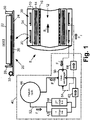
- an illustrative magnetic resonance imaging (MRI) device 8 includes a superconducting magnet 10, which in the illustrative embodiment is a horizontal solenoidal superconducting magnet 10 defining a horizontal bore 12 into which a patient or other imaging subject is inserted for MRI examination. A couch or other patient support (not shown) may be provided for loading the patient.
- the MRI device 8 further includes, in addition to the superconducting magnet 10, other components known in the MRI arts such as resistive magnetic field gradient coils 14, a whole-body radio frequency (RF) coil 16 (and/or one or more local RF coils, not shown), and so forth. These components are used in known ways to acquire MRI images.
- RF radio frequency
- the operating superconducting magnet 10 produces a static (B 0 ) magnetic field in an examination region within the bore 12.
- of this field may be 1.5 Tesla, 3.0 Tesla, 7.0 Tesla, or so forth.
- the B 0 magnetic field (statistically) orients nuclear spins, which are excited by RF pulses applied by the RF coil 16.
- the excited magnetic resonance is spatially limited and/or phase- and/or frequency-encoded by magnetic field gradients superimposed on the static (B 0 ) magnetic field in the examination region by the magnetic field gradient coils 14, and the thusly manipulated excited magnetic resonance are detected by the RF coil 16 to generate MRI imaging data.
- An image reconstruction algorithm suitable for the chosen spatial encoding may be applied to reconstruct an MRI image from the acquired MRI imaging data.
- Superconducting windings 22 are wrapped around an annular thermally conductive former 24, such as a copper or copper alloy hoop or ring that encircles the bore 12. If the former 24 is electrically conductive (which is the case for copper/copper alloy), then a thermally conductive but electrically insulating spacer 26 may be provided, for example one or more fiberglass sheets, provides electrical isolation of the superconducting windings 22 from the former 24.
- an inner insulating ring (not shown) may be provided at the inside diameter (ID) of the copper alloy substrate loop 24. Insulator elements 28, 30 may optionally be provided at the ends for positioning or other purposes.
- a pipe 32 which is part of the secondary coolant circuit (to be described) is brazed, welded, or otherwise secured with the copper alloy substrate loop 24, so that the substrate 24 and the supported superconducting conductor windings 22 are heat sinked by the secondary coolant circuit via the secured pipe 32.
- an illustrative two or (typically) more such magnet winding coils 20 is disposed in an evacuated dewar 34 to provide thermal isolation for the cooled assembly including the superconducting windings 22 and thermally conductive substrate hoop 24.
- a number of such winding coils 20 of different sizes, number of coil windings, or so forth are positioned in accord with a magnet design to produce the static (B 0 ) magnetic field with a high degree of spatial uniformity in an examination region within the bore 12.
- FIGURE 2 shows the cooling device 40 in a diagrammatic fashion.
- a diagrammatically indicated cold head 42, 44 includes a first stage helium cold station 42 and a second stage helium cold station 44.
- the cold head 42, 44 may be embodied by any cryogenic refrigerator operable to cool helium working fluid. While two cold stations are shown, the number of cold stations could instead be one or could be more than two. In a typical configuration, the first cold station 42 is at a higher temperature than the second cold station 44, but other configurations are possible.
- the cold head 42, 44 typically operates by a piston or the like (not shown) providing for cyclic compression and expansion of the working fluid (e.g. helium) to implement a thermodynamic cycle by which the working fluid is cooled.
- operation of the cold head 42, 44 is effective to liquefy helium gas to generate liquid helium (LHe) or a two-phase mixture of helium gas and LHe.
- LHe liquid helium
- FIGURE 1 This is the case in the illustrative embodiment of FIGURE 1 , in which a helium tank 46 serves as a vapor-liquid separator, with the LHe collecting at the bottom of the helium tank 46 and the balance of the volume of the helium tank 46 being filled by helium gas.
- the cryogenic cooling device 40 further includes a heat exchanger 50.
- a first flow loop 52 connects a cold sink with the heat exchanger 50.
- a second flow loop 54 connects a hot sink with the heat exchanger 50.
- the cold sink comprises the cold head 42, 44 and the helium tank 46, while the hot sink comprises the one or more magnet coils 20. More generally, however, the cold sink and the hot sink may be any masses connected with the heat exchanger 50 by respective first and second flow loops 52, 54 in which the cold sink is at a lower temperature than the hot sink.
- the cold sink is also at a temperature that is below room temperature.
- the first flow loop 52 is drawn using solid lines while the second flow loop 54 is drawn using dotted lines.
- the heat exchanger 50 may employ any configuration that brings the flow in the first flow loop 52 and the flow in the second flow loop 54 into sufficient proximity to enable suitably efficient heat transfer from the warmer coolant fluid flowing in the second flow loop 54 to the colder coolant fluid flowing in the first flow loop 52.
- the heat exchanger may have a shell-and-tube configuration (not shown) in which one coolant fluid flows in tubes contained in a surrounding shell through which the other coolant fluid flows.
- a counter-flow arrangement should be implemented in which flow in the pipes is in the opposite direction from flow in the shell. More generally, the specific layout of the heat exchanger defines a counter-flow arrangement which is diagrammatically indicated in the heat exchanger of FIGURE 1 by triangular flow direction indicators.
- passive one-way valves 62, 64 are provided to ensure the appropriate flow directions to achieve counter-flow in the heat exchanger 50. More particularly, a first passive one-way valve 62 is disposed on the first flow loop 52, and is oriented to allow flow in an allowed direction of flow F 1 in the first flow loop 52 and to block flow in an opposite blocked direction of flow in the first flow loop 52.
- the second passive one-way valve 64 is disposed on the second flow loop 54, and is oriented to allow flow in an allowed direction of flow F 2 in the second flow loop 54 and to block flow in an opposite blocked direction of flow in the second flow loop 54.
- the orientations of the passive one-way valves 62, 64 are chosen so that the combination of flow in the allowed direction of flow F 1 in the first flow loop 52 and flow in the allowed direction of flow F 2 in the second flow loop 54 produces counter-flow in the heat exchanger 50.
- the two passive one-way valves 62, 64 provide positive assurance that the flow directions that are established in the two flow loops 52, 54 are oriented correctly to provide counter-flow in the heat exchanger 50.
- the first flow loop 52 contains helium fluid as the working fluid (i.e. as the coolant fluid).
- the helium fluid in the first flow loop 52 is maintained at an elevated pressure, e.g. initially above 2000 psi in some embodiments. Initially, this helium fluid is single-phase helium gas; however, as the cold head operates to cool the helium gas the colder station 44 eventually reaches the temperature at which the helium at the pressure of the first flow loop 52 begins to liquefy (e.g.
- the helium tank 46 acts as a vapor-liquid separator, with the LHe collecting at the bottom of the tank 46 and providing a coolant reservoir to maintain the helium fluid in the first flow loop 52 at cryogenic temperature and delay magnet quenching in the event of temporary loss of power to the cold head 42, 44.
- the pressure in the first flow loop 52 also decreases during cooldown, to a pressure on the order of a few psi (e.g., about 8 psi in some embodiments) as the helium is partially liquefied in the final operational state.
- the second flow loop 54 also contains helium fluid as the working fluid (i.e. coolant fluid); however, the helium fluid in the second flow loop 54 remains in the gas phase throughout the cooldown (this ensures that thermal siphon flow is maintained throughout the cooldown) and is hence referred to herein as helium gas.
- the helium gas in the second flow loop 54 is initially at a few hundred psi, and eventually cools down to a temperature of around 3 K to 4 K, i.e. comparable to (though slightly above) the temperature of the helium fluid in the first flow loop 52.
- the helium gas in the second flow loop 54 in the operational state the helium gas in the second flow loop 54 is also at a pressure of a few psi in the final operational state.
- cryogenic cooling device 40 is advantageously entirely passive except for electromechanical input to drive the piston or other mechanism of the cold head 42, 44.
- the components of the cooling device 40 and the spatial layout of the flow loops 52, 54 can advantageously be arranged in any fashion, without the need to provide gravitational flow biasing by judicious arrangement of these components and layout of the flow loops.
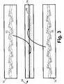
- each passive one-way valve is a Tesla valve.
- FIGURE 3 illustrates one-way valve 62 by way of illustrative example, but the other one-way valve 64 can have the same construction.
- the illustrative Tesla valve 62 comprises a first stainless steel block 70 having a milled Tesla valve conduit pattern 72, and a second stainless steel block 74 having a milled Tesla valve conduit pattern 76.
- the first and second stainless steel blocks 70, 74 hermetically sealed together, for example by brazing to form a brazed joint 78, with the Tesla valve conduit patterns 72, 76 of the first and second stainless steel blocks 70, 74 defining a Tesla valve conduit 80 (hidden feature shown by dashed lines in the assembled one-way valve 62 of FIGURE 3 ) passing though the hermetically sealed first and second stainless steel blocks forming the one-way valve 62.
- the Tesla valve conduit presents a relatively unimpeded path for fluid flow in the allowed flow direction (the direction from left to right in FIGURE 3 ), while presenting a tortuous flow path for fluid flow in the blocked flow direction (the direction from right to left in FIGURE 3 ).
- the manufacturing approach disclosed herein provides the Tesla valve with the brazed joint 78 having a large contact area so as to provide hermetic sealing of the Tesla valve conduit 80 which has negligible leakage even for low molecular density helium working fluid. While brazing of stainless steel blocks 70, 74 having milled Tesla conduit patterns 72, 76 is a preferred approach, other machining techniques can be used to form the Tesla conduit patterns 72, 76 and/or to join the two blocks 70, 74 to form the joint 78.
- the Tesla valve is well-suited for use as the passive one-way valves 62, 64 of the cryogenic cooling device 40 because these valves 62, 64 are not required to have very high differential resistance in the allowed flow direction versus the blocked flow direction.
- the flow directions in the respective first and second flow loops 52, 54 are determined on initial startup by the overall resistance to flow in one direction versus the other.
- the passive one-way valve 62 need only have sufficient directional bias to ensure that overall flow resistance of the first flow loop 52 in the allowed direction F 1 is lower than the flow resistance in the opposite direction.
- the passive one-way valve 64 need only have sufficient directional bias to ensure that overall flow resistance of the second flow loop 54 in the allowed direction F 2 is lower than the flow resistance in the opposite direction.
- the Tesla valve is readily capable of providing this level of directional bias.
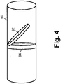
- FIGURE 4 presents an alternative passive one way valve embodiment of the flap check valve design, in which a valve body 90 (e.g.
- a short length of pipe or tubing defines the flow path through the flap check valve, and a hinged valve flap 92 mates with a valve seat 94 so that the valve flap 92 can move away from the valve seat 94 only in one direction (to the right in FIGURE 4 ) to allow flow in the allowed direction (from left to right in FIGURE 4 ); whereas, flow in the blocked direction (from right to left in FIGURE 4 ) firmly presses the valve flap 92 into the valve seat 94 to block the flow. While such a valve is suitable for use as the passive one-way valves 62, 64, it has certain disadvantages, such as the potential for freeze-up of the hinge at cryogenic temperature if the working fluid contains residual water content.
- cryogenic cooling device 40 operating with helium working fluid
- the disclosed improvements may more generally be employed in any cryogenic cooling device, e.g. also in one employing liquid nitrogen, air, chilled water, or another working fluid.
- the disclosed improvements may even more generally comprise any thermosiphion cooling device including a heat exchanger and first and second flow loops with passive one way valves oriented to ensure a combination of flow in allowed directions in the respective first and second flow loops that produces counter-flow in the heat exchanger.
- the heat exchanger 50 is a single-stage heat exchanger in which the flows F1, F2 are directly thermally coupled.
- the heat exchanger it is contemplated for the heat exchanger to be a multi-stage heat exchanger in which at least one intermediate flow (FI, not shown) is thermally coupled with the flow F1 and with the flow flow F2 so as to indirectly transfer heat in two stages (F2 ⁇ FI ⁇ F1).
- the one-way valves 62, 64 are still advantageously employed to establish the correct flow directions to establish counter-flow of flows F1, F2 in the (multi-stage) heat exchanger; and additionally, a third one-way valve (now shown) is preferably included to establish the correct flow direction for the counter flow in the intermediate FI fluid loop.
Landscapes
- Engineering & Computer Science (AREA)
- Physics & Mathematics (AREA)
- Mechanical Engineering (AREA)
- Thermal Sciences (AREA)
- General Engineering & Computer Science (AREA)
- Condensed Matter Physics & Semiconductors (AREA)
- General Physics & Mathematics (AREA)
- Electromagnetism (AREA)
- Power Engineering (AREA)
- Magnetic Resonance Imaging Apparatus (AREA)
Claims (15)
- Système comprenant :un échangeur de chaleur (50), un dissipateur de froid (42, 44, 46) et un dissipateur de chaleur (20) ;une première boucle d'écoulement (52) reliant le dissipateur de froid (42, 44, 46) et l'échangeur thermique ;une seconde boucle d'écoulement (54) reliant le dissipateur de chaleur (20) et l'échangeur de chaleur ; une première soupape (62) unidirectionnelle passive disposée sur la première boucle d'écoulement et orientée pour permettre l'écoulement dans un sens d'écoulement (F1) autorisé dans la première boucle d'écoulement et pour bloquer l'écoulement dans un sens d'écoulement bloqué opposé dans la première boucle d'écoulement ; etune seconde soupape (64) unidirectionnelle passive disposée sur la seconde boucle d'écoulement et orientée pour permettre l'écoulement dans un sens d'écoulement (F2) autorisé dans la seconde boucle d'écoulement et pour bloquer l'écoulement dans un sens d'écoulement bloqué opposé dans la seconde boucle d'écoulement ;dans lequel la combinaison d'écoulement dans le sens d'écoulement autorisé dans la première boucle d'écoulement et d'écoulement dans le sens d'écoulement autorisé dans la seconde boucle d'écoulement est conçue de telle sorte qu'elle produit un contre-écoulement dans l'échangeur de chaleur.
- Système selon la revendication 1, dans lequel la première soupape (62) unidirectionnelle passive comprend une première soupape Tesla et la seconde soupape (64) unidirectionnelle passive comprend une seconde soupape Tesla.
- Système selon la revendication 2, dans lequel la première soupape Tesla (62) et la seconde soupape Tesla (64) comprennent respectivement :un premier bloc (70) en acier inoxydable présentant un motif (72) fraisé de conduit de soupape Tesla ;un second bloc (74) en acier inoxydable présentant un motif (76) fraisé de conduit de soupape Tesla ;les premier et second blocs en acier inoxydable étant ensemble hermétiquement scellés avec les motifs de conduit de soupape Tesla des premier et second blocs en acier inoxydable définissant un conduit de soupape Tesla (80) passant à travers les premier et second blocs en acier inoxydable hermétiquement scellés.
- Système selon la revendication 3, dans lequel les premier et second blocs (70, 74) en acier inoxydable de chaque soupape Tesla (62, 64) sont scellés ensemble hermétiquement par un joint brasé (78).
- Système selon l'une quelconque des revendications 1 à 4, comprenant en outre :de l'hélium fluide disposé dans la première boucle d'écoulement (52) ; etde l'hélium gazeux disposé dans la seconde boucle d'écoulement (54).
- Système selon l'une quelconque des revendications 1 à 5, dans lequel aucune pompe mécanique n'est reliée pour entraîner l'écoulement dans la seconde boucle d'écoulement (54).
- Système selon l'une quelconque des revendications 1 à 6 comprenant en outre :un enroulement (20) d'aimant supraconducteur, le dissipateur de chaleur comprenant l'enroulement d'aimant supraconducteur ; etun plongeur (42, 44) cryogénique, le dissipateur de froid (42, 44, 46) comprenant le plongeur cryogénique.
- Système selon la revendication 7 comprenant en outre :
un séparateur (46) de phase vapeur-fluide, le dissipateur de froid (42, 44, 46) comprenant en outre le séparateur de phase vapeur-fluide. - Dispositif d'imagerie par résonance magnétique (IRM) comprenant :un aimant (10) comprenant au moins un enroulement (20) magnétique supraconducteur ;un plongeur (42, 44) cryogénique ; etsystème selon l'une quelconque des revendications 1 à 7, dans lequel le dissipateur de chaleur du système comprend l'au moins un enroulement magnétique supraconducteur et le dissipateur de froid du système comprend le plongeur cryogénique et un réservoir (46) d'hélium fluide.
- Procédé de réfrigération comprenant :l'écoulement du premier fluide réfrigérant à travers une première boucle d'écoulement (52), laquelle relie un dissipateur de froid (42, 44, 46) et un échangeur de chaleur (50) ;l'écoulement d'un second fluide réfrigérant à travers une seconde boucle d'écoulement (54), laquelle relie un dissipateur de chaleur (20) et l'échangeur de chaleur ; etla contrainte de l'écoulement du premier fluide réfrigérant et l'écoulement du second fluide réfrigérant pour produire un contre-écoulement dans l'échangeur de chaleur :par utilisation d'une première soupape (62) unidirectionnelle passive pour permettre l'écoulement du premier fluide réfrigérant dans la première boucle d'écoulement dans un sens (F1) autorisé tout en bloquant l'écoulement dans un sens bloqué opposé, etpar utilisation d'une seconde soupape (64) unidirectionnelle passive pour permettre l'écoulement du second fluide réfrigérant dans la seconde boucle d'écoulement dans un sens (F2) autorisé tout en bloquant l'écoulement dans un sens bloqué opposé.
- Procédé de réfrigération selon la revendication 10, dans lequel la première soupape (62) unidirectionnelle passive comprend une première soupape Tesla et la seconde soupape (64) unidirectionnelle passive comprend une seconde soupape Tesla.
- Procédé de réfrigération selon la revendication 11, comprenant en outre la construction respective de la première soupape Tesla (62) et de la seconde soupape Tesla (64) :par fraisage d'un modèle (72) de conduit de soupape Tesla dans un premier bloc (70) en acier inoxydable ;par fraisage d'un modèle (76) de conduit de soupape Tesla dans un second bloc (74) en acier inoxydable ; etpar scellage hermétique des premier et second blocs en acier inoxydable avec les motifs de conduit de soupape Tesla des premier et second blocs en acier inoxydable conçus pour définir un conduit de soupape Tesla (80) passant à travers les premier et second blocs en acier inoxydable hermétiquement scellés.
- Procédé de réfrigération selon la revendication 12, dans lequel le scellement hermétique comprend le brasage des premier et second blocs (70, 74) d'acier inoxydable ensemble.
- Procédé de réfrigération selon l'une quelconque des revendications 10 à 13, dans lequel le premier fluide réfrigérant est de l'hélium fluide et le second fluide réfrigérant est de l'hélium gazeux.
- Procédé de réfrigération selon la revendication 14 comprenant en outre :
la collecte d'une phase d'hélium fluide de l'hélium fluide s'écoulant à travers la première boucle d'écoulement (52) dans un réservoir (46) d'hélium relié à la première boucle d'écoulement.
Applications Claiming Priority (2)
| Application Number | Priority Date | Filing Date | Title |
|---|---|---|---|
| US201662404907P | 2016-10-06 | 2016-10-06 | |
| PCT/EP2017/075203 WO2018065458A1 (fr) | 2016-10-06 | 2017-10-04 | Sollicitation de direction d'écoulement passif de thermosiphon cryogénique |
Publications (2)
| Publication Number | Publication Date |
|---|---|
| EP3523582A1 EP3523582A1 (fr) | 2019-08-14 |
| EP3523582B1 true EP3523582B1 (fr) | 2022-05-18 |
Family
ID=60143678
Family Applications (1)
| Application Number | Title | Priority Date | Filing Date |
|---|---|---|---|
| EP17787122.5A Active EP3523582B1 (fr) | 2016-10-06 | 2017-10-04 | Sollicitation de direction d'écoulement passif de thermosiphon cryogénique |
Country Status (5)
| Country | Link |
|---|---|
| US (1) | US11275136B2 (fr) |
| EP (1) | EP3523582B1 (fr) |
| JP (1) | JP7096238B2 (fr) |
| CN (1) | CN109804208B (fr) |
| WO (1) | WO2018065458A1 (fr) |
Families Citing this family (12)
| Publication number | Priority date | Publication date | Assignee | Title |
|---|---|---|---|---|
| CN110769643B (zh) * | 2018-07-27 | 2021-05-04 | 宏碁股份有限公司 | 散热模块 |
| FR3097948B1 (fr) | 2019-06-26 | 2021-06-25 | Lair Liquide Sa Pour Letude Et L’Exploitation Des Procedes Georges Claude | Refroidisseur cryogénique pour détecteur de rayonnement notamment dans un engin spatial |
| US11835607B2 (en) * | 2020-07-14 | 2023-12-05 | General Electric Company | Auxiliary cryogen storage for magnetic resonance imaging applications |
| CN112197033B (zh) * | 2020-09-21 | 2022-07-26 | 周天桥 | 一种可调速的特斯拉阀 |
| CN114427380B (zh) * | 2020-10-13 | 2024-06-18 | 中国石油化工股份有限公司 | 一种井下流体单向导通高速截止阀及使用其的方法 |
| CN112228596A (zh) * | 2020-11-06 | 2021-01-15 | 刘西振 | 一种具有单向流体加速功能的单向阀 |
| US11719236B2 (en) * | 2021-06-17 | 2023-08-08 | United States Department Of Energy | Flow control valve |
| CN113325140B (zh) * | 2021-07-08 | 2022-08-05 | 全球能源互联网研究院有限公司 | 一种基于特斯拉阀的气体纯度检测净化系统 |
| GB202113063D0 (en) * | 2021-09-14 | 2021-10-27 | Rolls Royce Plc | Fluid pump |
| CN114220985A (zh) * | 2021-12-14 | 2022-03-22 | 清华大学 | 一种可变进气式燃料电池流场及其控制方法 |
| CN114739056B (zh) * | 2022-04-20 | 2023-02-10 | 华中科技大学 | 一种变径节流管及其应用 |
| CN115167572B (zh) * | 2022-06-30 | 2024-03-22 | 浙江工业大学 | 一种集成式微温控器件及其制备方法 |
Family Cites Families (19)
| Publication number | Priority date | Publication date | Assignee | Title |
|---|---|---|---|---|
| US1329559A (en) | 1916-02-21 | 1920-02-03 | Tesla Nikola | Valvular conduit |
| US5598721A (en) * | 1989-03-08 | 1997-02-04 | Rocky Research | Heating and air conditioning systems incorporating solid-vapor sorption reactors capable of high reaction rates |
| JPH1062127A (ja) * | 1996-08-13 | 1998-03-06 | Fuji Xerox Co Ltd | 画像測定方法及び画像測定装置 |
| CA2295565A1 (fr) | 1998-05-22 | 1999-12-02 | Sumitomo Electric Industries, Ltd. | Procede et dispositif de refroidissement d'un supraconducteur |
| JP2001004236A (ja) * | 1999-06-24 | 2001-01-12 | Mitsubishi Electric Corp | 極低温冷却装置および極低温冷却方法 |
| US6442949B1 (en) * | 2001-07-12 | 2002-09-03 | General Electric Company | Cryongenic cooling refrigeration system and method having open-loop short term cooling for a superconducting machine |
| DE102004053972B3 (de) | 2004-11-09 | 2006-07-20 | Bruker Biospin Gmbh | NMR-Spektrometer mit gemeinsamen Refrigerator zum Kühlen von NMR-Probenkopf und Kryostat |
| JP4381998B2 (ja) | 2005-02-24 | 2009-12-09 | 株式会社日立製作所 | 液冷システム |
| GB2462626B (en) | 2008-08-14 | 2010-12-29 | Siemens Magnet Technology Ltd | Cooled current leads for cooled equipment |
| US8676282B2 (en) | 2010-10-29 | 2014-03-18 | General Electric Company | Superconducting magnet coil support with cooling and method for coil-cooling |
| CN103842746B (zh) | 2011-09-28 | 2016-02-17 | 皇家飞利浦有限公司 | 用于无致冷剂mri磁体的高效热交换器 |
| US9958519B2 (en) | 2011-12-22 | 2018-05-01 | General Electric Company | Thermosiphon cooling for a magnet imaging system |
| EP2734020B1 (fr) | 2012-11-19 | 2017-07-12 | ABB Schweiz AG | Agencement de refroidissement comprenant un thermosiphon à deux phases destiné à refroidir une multiplicité de dispositifs électriques |
| US8650877B1 (en) * | 2013-03-11 | 2014-02-18 | Gary R. Gustafson | Solar panels that generate electricity and extract heat: system and method |
| DE102013213020A1 (de) | 2013-07-03 | 2015-01-08 | Bruker Biospin Ag | Verfahren zum Umrüsten einer Kryostatanordnung auf Umlaufkühlung |
| JP6458031B2 (ja) * | 2013-11-13 | 2019-01-23 | コーニンクレッカ フィリップス エヌ ヴェKoninklijke Philips N.V. | 熱効率的なライドスルーシステムを有する超電導磁石システム及び超電導磁石システムを冷却する方法 |
| US10184711B2 (en) | 2014-05-19 | 2019-01-22 | General Electric Company | Cryogenic cooling system |
| CN204730538U (zh) | 2015-05-28 | 2015-10-28 | 光宇清源(香港)有限公司 | 热虹吸系统及流体单向控制器 |
| JP2020014236A (ja) | 2019-09-24 | 2020-01-23 | 株式会社東芝 | 無線通信装置、無線通信システム、無線通信方法およびプログラム |
-
2017
- 2017-10-04 EP EP17787122.5A patent/EP3523582B1/fr active Active
- 2017-10-04 US US16/338,789 patent/US11275136B2/en active Active
- 2017-10-04 CN CN201780061413.2A patent/CN109804208B/zh active Active
- 2017-10-04 JP JP2019518312A patent/JP7096238B2/ja active Active
- 2017-10-04 WO PCT/EP2017/075203 patent/WO2018065458A1/fr unknown
Also Published As
| Publication number | Publication date |
|---|---|
| WO2018065458A1 (fr) | 2018-04-12 |
| JP7096238B2 (ja) | 2022-07-05 |
| JP2020501624A (ja) | 2020-01-23 |
| CN109804208B (zh) | 2021-06-22 |
| CN109804208A (zh) | 2019-05-24 |
| EP3523582A1 (fr) | 2019-08-14 |
| US20210278491A1 (en) | 2021-09-09 |
| US11275136B2 (en) | 2022-03-15 |
Similar Documents
| Publication | Publication Date | Title |
|---|---|---|
| EP3523582B1 (fr) | Sollicitation de direction d'écoulement passif de thermosiphon cryogénique | |
| EP2519786B1 (fr) | Système de refroidissement cryogénique avec un commutateur thermique tubulaire | |
| JP4417247B2 (ja) | 超伝導磁石と冷凍ユニットとを備えたmri装置 | |
| US9494344B2 (en) | Method for reconfiguring a cryostat configuration for recirculation cooling | |
| US20150332829A1 (en) | Cryogenic cooling system | |
| EP1586833A2 (fr) | Dispositif de refroidissement | |
| EP3069159B1 (fr) | Système d'aimant supraconducteur comprenant un système anti-panne thermiquement efficace et procédé de refroidissement de système d'aimant supraconducteur | |
| US20170284725A1 (en) | Cryostat with a first and a second helium tank, which are separated from one another in a liquid-tight manner at least in a lower part | |
| JP6378039B2 (ja) | 超電導磁石およびmri装置、nmr装置 | |
| JP2015012193A (ja) | 超電導磁石装置 | |
| US6289681B1 (en) | Superconducting magnet split cryostat interconnect assembly | |
| JPH08222429A (ja) | 極低温装置 | |
| JP2008538856A (ja) | クライオスタットアセンブリ | |
| US20150108980A1 (en) | Apparatus for reducing vibrations in a pulse tube refrigerator such as for magnetic resonance imaging systems | |
| JPH11248326A (ja) | 冷凍機 | |
| JP6164409B2 (ja) | Nmrシステム | |
| JP2016211795A5 (fr) | ||
| Green | Cooling the MICE magnets using small cryogenic coolers | |
| JP2007078310A (ja) | 極低温冷却装置 | |
| US20200058423A1 (en) | Thermal bus heat exchanger for superconducting magnet | |
| Choi et al. | Closed-loop cryogenic cooling for a 21 T FT-ICR magnet system | |
| JP2018505373A (ja) | 閉サイクル式冷凍剤再循環システム及び方法 | |
| JPH09106906A (ja) | 伝導冷却式超電導磁石 |
Legal Events
| Date | Code | Title | Description |
|---|---|---|---|
| STAA | Information on the status of an ep patent application or granted ep patent |
Free format text: STATUS: UNKNOWN |
|
| STAA | Information on the status of an ep patent application or granted ep patent |
Free format text: STATUS: THE INTERNATIONAL PUBLICATION HAS BEEN MADE |
|
| PUAI | Public reference made under article 153(3) epc to a published international application that has entered the european phase |
Free format text: ORIGINAL CODE: 0009012 |
|
| STAA | Information on the status of an ep patent application or granted ep patent |
Free format text: STATUS: REQUEST FOR EXAMINATION WAS MADE |
|
| 17P | Request for examination filed |
Effective date: 20190506 |
|
| AK | Designated contracting states |
Kind code of ref document: A1 Designated state(s): AL AT BE BG CH CY CZ DE DK EE ES FI FR GB GR HR HU IE IS IT LI LT LU LV MC MK MT NL NO PL PT RO RS SE SI SK SM TR |
|
| AX | Request for extension of the european patent |
Extension state: BA ME |
|
| DAV | Request for validation of the european patent (deleted) | ||
| DAX | Request for extension of the european patent (deleted) | ||
| RAP1 | Party data changed (applicant data changed or rights of an application transferred) |
Owner name: KONINKLIJKE PHILIPS N.V. |
|
| GRAP | Despatch of communication of intention to grant a patent |
Free format text: ORIGINAL CODE: EPIDOSNIGR1 |
|
| STAA | Information on the status of an ep patent application or granted ep patent |
Free format text: STATUS: GRANT OF PATENT IS INTENDED |
|
| INTG | Intention to grant announced |
Effective date: 20211214 |
|
| GRAS | Grant fee paid |
Free format text: ORIGINAL CODE: EPIDOSNIGR3 |
|
| GRAA | (expected) grant |
Free format text: ORIGINAL CODE: 0009210 |
|
| STAA | Information on the status of an ep patent application or granted ep patent |
Free format text: STATUS: THE PATENT HAS BEEN GRANTED |
|
| AK | Designated contracting states |
Kind code of ref document: B1 Designated state(s): AL AT BE BG CH CY CZ DE DK EE ES FI FR GB GR HR HU IE IS IT LI LT LU LV MC MK MT NL NO PL PT RO RS SE SI SK SM TR |
|
| REG | Reference to a national code |
Ref country code: GB Ref legal event code: FG4D |
|
| REG | Reference to a national code |
Ref country code: CH Ref legal event code: EP |
|
| REG | Reference to a national code |
Ref country code: IE Ref legal event code: FG4D |
|
| REG | Reference to a national code |
Ref country code: DE Ref legal event code: R096 Ref document number: 602017057667 Country of ref document: DE |
|
| REG | Reference to a national code |
Ref country code: AT Ref legal event code: REF Ref document number: 1493366 Country of ref document: AT Kind code of ref document: T Effective date: 20220615 |
|
| REG | Reference to a national code |
Ref country code: DE Ref legal event code: R084 Ref document number: 602017057667 Country of ref document: DE |
|
| REG | Reference to a national code |
Ref country code: GB Ref legal event code: 746 Effective date: 20220727 |
|
| REG | Reference to a national code |
Ref country code: LT Ref legal event code: MG9D |
|
| REG | Reference to a national code |
Ref country code: NL Ref legal event code: MP Effective date: 20220518 |
|
| REG | Reference to a national code |
Ref country code: AT Ref legal event code: MK05 Ref document number: 1493366 Country of ref document: AT Kind code of ref document: T Effective date: 20220518 |
|
| PG25 | Lapsed in a contracting state [announced via postgrant information from national office to epo] |
Ref country code: SE Free format text: LAPSE BECAUSE OF FAILURE TO SUBMIT A TRANSLATION OF THE DESCRIPTION OR TO PAY THE FEE WITHIN THE PRESCRIBED TIME-LIMIT Effective date: 20220518 Ref country code: PT Free format text: LAPSE BECAUSE OF FAILURE TO SUBMIT A TRANSLATION OF THE DESCRIPTION OR TO PAY THE FEE WITHIN THE PRESCRIBED TIME-LIMIT Effective date: 20220919 Ref country code: NO Free format text: LAPSE BECAUSE OF FAILURE TO SUBMIT A TRANSLATION OF THE DESCRIPTION OR TO PAY THE FEE WITHIN THE PRESCRIBED TIME-LIMIT Effective date: 20220818 Ref country code: NL Free format text: LAPSE BECAUSE OF FAILURE TO SUBMIT A TRANSLATION OF THE DESCRIPTION OR TO PAY THE FEE WITHIN THE PRESCRIBED TIME-LIMIT Effective date: 20220518 Ref country code: LT Free format text: LAPSE BECAUSE OF FAILURE TO SUBMIT A TRANSLATION OF THE DESCRIPTION OR TO PAY THE FEE WITHIN THE PRESCRIBED TIME-LIMIT Effective date: 20220518 Ref country code: HR Free format text: LAPSE BECAUSE OF FAILURE TO SUBMIT A TRANSLATION OF THE DESCRIPTION OR TO PAY THE FEE WITHIN THE PRESCRIBED TIME-LIMIT Effective date: 20220518 Ref country code: GR Free format text: LAPSE BECAUSE OF FAILURE TO SUBMIT A TRANSLATION OF THE DESCRIPTION OR TO PAY THE FEE WITHIN THE PRESCRIBED TIME-LIMIT Effective date: 20220819 Ref country code: FI Free format text: LAPSE BECAUSE OF FAILURE TO SUBMIT A TRANSLATION OF THE DESCRIPTION OR TO PAY THE FEE WITHIN THE PRESCRIBED TIME-LIMIT Effective date: 20220518 Ref country code: ES Free format text: LAPSE BECAUSE OF FAILURE TO SUBMIT A TRANSLATION OF THE DESCRIPTION OR TO PAY THE FEE WITHIN THE PRESCRIBED TIME-LIMIT Effective date: 20220518 Ref country code: BG Free format text: LAPSE BECAUSE OF FAILURE TO SUBMIT A TRANSLATION OF THE DESCRIPTION OR TO PAY THE FEE WITHIN THE PRESCRIBED TIME-LIMIT Effective date: 20220818 Ref country code: AT Free format text: LAPSE BECAUSE OF FAILURE TO SUBMIT A TRANSLATION OF THE DESCRIPTION OR TO PAY THE FEE WITHIN THE PRESCRIBED TIME-LIMIT Effective date: 20220518 |
|
| PG25 | Lapsed in a contracting state [announced via postgrant information from national office to epo] |
Ref country code: RS Free format text: LAPSE BECAUSE OF FAILURE TO SUBMIT A TRANSLATION OF THE DESCRIPTION OR TO PAY THE FEE WITHIN THE PRESCRIBED TIME-LIMIT Effective date: 20220518 Ref country code: PL Free format text: LAPSE BECAUSE OF FAILURE TO SUBMIT A TRANSLATION OF THE DESCRIPTION OR TO PAY THE FEE WITHIN THE PRESCRIBED TIME-LIMIT Effective date: 20220518 Ref country code: LV Free format text: LAPSE BECAUSE OF FAILURE TO SUBMIT A TRANSLATION OF THE DESCRIPTION OR TO PAY THE FEE WITHIN THE PRESCRIBED TIME-LIMIT Effective date: 20220518 Ref country code: IS Free format text: LAPSE BECAUSE OF FAILURE TO SUBMIT A TRANSLATION OF THE DESCRIPTION OR TO PAY THE FEE WITHIN THE PRESCRIBED TIME-LIMIT Effective date: 20220918 |
|
| PG25 | Lapsed in a contracting state [announced via postgrant information from national office to epo] |
Ref country code: SM Free format text: LAPSE BECAUSE OF FAILURE TO SUBMIT A TRANSLATION OF THE DESCRIPTION OR TO PAY THE FEE WITHIN THE PRESCRIBED TIME-LIMIT Effective date: 20220518 Ref country code: SK Free format text: LAPSE BECAUSE OF FAILURE TO SUBMIT A TRANSLATION OF THE DESCRIPTION OR TO PAY THE FEE WITHIN THE PRESCRIBED TIME-LIMIT Effective date: 20220518 Ref country code: RO Free format text: LAPSE BECAUSE OF FAILURE TO SUBMIT A TRANSLATION OF THE DESCRIPTION OR TO PAY THE FEE WITHIN THE PRESCRIBED TIME-LIMIT Effective date: 20220518 Ref country code: EE Free format text: LAPSE BECAUSE OF FAILURE TO SUBMIT A TRANSLATION OF THE DESCRIPTION OR TO PAY THE FEE WITHIN THE PRESCRIBED TIME-LIMIT Effective date: 20220518 Ref country code: DK Free format text: LAPSE BECAUSE OF FAILURE TO SUBMIT A TRANSLATION OF THE DESCRIPTION OR TO PAY THE FEE WITHIN THE PRESCRIBED TIME-LIMIT Effective date: 20220518 Ref country code: CZ Free format text: LAPSE BECAUSE OF FAILURE TO SUBMIT A TRANSLATION OF THE DESCRIPTION OR TO PAY THE FEE WITHIN THE PRESCRIBED TIME-LIMIT Effective date: 20220518 |
|
| REG | Reference to a national code |
Ref country code: DE Ref legal event code: R097 Ref document number: 602017057667 Country of ref document: DE |
|
| PLBE | No opposition filed within time limit |
Free format text: ORIGINAL CODE: 0009261 |
|
| STAA | Information on the status of an ep patent application or granted ep patent |
Free format text: STATUS: NO OPPOSITION FILED WITHIN TIME LIMIT |
|
| PG25 | Lapsed in a contracting state [announced via postgrant information from national office to epo] |
Ref country code: AL Free format text: LAPSE BECAUSE OF FAILURE TO SUBMIT A TRANSLATION OF THE DESCRIPTION OR TO PAY THE FEE WITHIN THE PRESCRIBED TIME-LIMIT Effective date: 20220518 |
|
| 26N | No opposition filed |
Effective date: 20230221 |
|
| PG25 | Lapsed in a contracting state [announced via postgrant information from national office to epo] |
Ref country code: SI Free format text: LAPSE BECAUSE OF FAILURE TO SUBMIT A TRANSLATION OF THE DESCRIPTION OR TO PAY THE FEE WITHIN THE PRESCRIBED TIME-LIMIT Effective date: 20220518 Ref country code: MC Free format text: LAPSE BECAUSE OF FAILURE TO SUBMIT A TRANSLATION OF THE DESCRIPTION OR TO PAY THE FEE WITHIN THE PRESCRIBED TIME-LIMIT Effective date: 20220518 |
|
| REG | Reference to a national code |
Ref country code: CH Ref legal event code: PL |
|
| REG | Reference to a national code |
Ref country code: BE Ref legal event code: MM Effective date: 20221031 |
|
| PG25 | Lapsed in a contracting state [announced via postgrant information from national office to epo] |
Ref country code: LU Free format text: LAPSE BECAUSE OF NON-PAYMENT OF DUE FEES Effective date: 20221004 |
|
| PG25 | Lapsed in a contracting state [announced via postgrant information from national office to epo] |
Ref country code: LI Free format text: LAPSE BECAUSE OF NON-PAYMENT OF DUE FEES Effective date: 20221031 Ref country code: CH Free format text: LAPSE BECAUSE OF NON-PAYMENT OF DUE FEES Effective date: 20221031 |
|
| PG25 | Lapsed in a contracting state [announced via postgrant information from national office to epo] |
Ref country code: BE Free format text: LAPSE BECAUSE OF NON-PAYMENT OF DUE FEES Effective date: 20221031 |
|
| PG25 | Lapsed in a contracting state [announced via postgrant information from national office to epo] |
Ref country code: IE Free format text: LAPSE BECAUSE OF NON-PAYMENT OF DUE FEES Effective date: 20221004 |
|
| PGFP | Annual fee paid to national office [announced via postgrant information from national office to epo] |
Ref country code: GB Payment date: 20231024 Year of fee payment: 7 |
|
| PG25 | Lapsed in a contracting state [announced via postgrant information from national office to epo] |
Ref country code: IT Free format text: LAPSE BECAUSE OF FAILURE TO SUBMIT A TRANSLATION OF THE DESCRIPTION OR TO PAY THE FEE WITHIN THE PRESCRIBED TIME-LIMIT Effective date: 20220518 |
|
| PGFP | Annual fee paid to national office [announced via postgrant information from national office to epo] |
Ref country code: FR Payment date: 20231026 Year of fee payment: 7 Ref country code: DE Payment date: 20231027 Year of fee payment: 7 |
|
| PG25 | Lapsed in a contracting state [announced via postgrant information from national office to epo] |
Ref country code: HU Free format text: LAPSE BECAUSE OF FAILURE TO SUBMIT A TRANSLATION OF THE DESCRIPTION OR TO PAY THE FEE WITHIN THE PRESCRIBED TIME-LIMIT; INVALID AB INITIO Effective date: 20171004 |
|
| PG25 | Lapsed in a contracting state [announced via postgrant information from national office to epo] |
Ref country code: CY Free format text: LAPSE BECAUSE OF FAILURE TO SUBMIT A TRANSLATION OF THE DESCRIPTION OR TO PAY THE FEE WITHIN THE PRESCRIBED TIME-LIMIT Effective date: 20220511 |
|
| PG25 | Lapsed in a contracting state [announced via postgrant information from national office to epo] |
Ref country code: MK Free format text: LAPSE BECAUSE OF FAILURE TO SUBMIT A TRANSLATION OF THE DESCRIPTION OR TO PAY THE FEE WITHIN THE PRESCRIBED TIME-LIMIT Effective date: 20220511 |
|
| PG25 | Lapsed in a contracting state [announced via postgrant information from national office to epo] |
Ref country code: MT Free format text: LAPSE BECAUSE OF FAILURE TO SUBMIT A TRANSLATION OF THE DESCRIPTION OR TO PAY THE FEE WITHIN THE PRESCRIBED TIME-LIMIT Effective date: 20220511 |