EP3519765B1 - Ultraschallmessanordnung und verfahren zum erfassen der wandstärke eines rohrs - Google Patents
Ultraschallmessanordnung und verfahren zum erfassen der wandstärke eines rohrs Download PDFInfo
- Publication number
- EP3519765B1 EP3519765B1 EP17800736.5A EP17800736A EP3519765B1 EP 3519765 B1 EP3519765 B1 EP 3519765B1 EP 17800736 A EP17800736 A EP 17800736A EP 3519765 B1 EP3519765 B1 EP 3519765B1
- Authority
- EP
- European Patent Office
- Prior art keywords
- main body
- measuring arrangement
- base body
- pipe
- another
- Prior art date
- Legal status (The legal status is an assumption and is not a legal conclusion. Google has not performed a legal analysis and makes no representation as to the accuracy of the status listed.)
- Active
Links
Images




Classifications
-
- G—PHYSICS
- G01—MEASURING; TESTING
- G01B—MEASURING LENGTH, THICKNESS OR SIMILAR LINEAR DIMENSIONS; MEASURING ANGLES; MEASURING AREAS; MEASURING IRREGULARITIES OF SURFACES OR CONTOURS
- G01B17/00—Measuring arrangements characterised by the use of infrasonic, sonic or ultrasonic vibrations
- G01B17/02—Measuring arrangements characterised by the use of infrasonic, sonic or ultrasonic vibrations for measuring thickness
Definitions
- the present invention relates to a measuring arrangement for detecting the wall thickness of a pipe, as defined in claim 1.
- the present invention relates to a method for detecting the wall thickness of a pipe using such a measuring arrangement as defined in claim 9.
- the US 2012/0167688 A1 discloses a measuring arrangement (100) for detecting the wall thickness of a pipe (101), comprising a test head ( Fig. 2 ) with a base body (270) receiving an ultrasound probe (210), which defines a base body support surface (212) on its underside, the test head having two wing elements (220, 230), each of which defines a wing element support surface (262, 263) on its undersides (see also 3A and 3B ) and pivotable on the base body in such a way that it is essentially parallel to one another and in a longitudinal direction ( Fig. 4 ) extending swivel axes ( Fig. 4 ) are held so that the wing element contact surfaces can be moved towards and away from each other ( Fig. 4 ).
- the CN 201053880 Y discloses a measuring arrangement ( Fig. 1 ) for detecting the wall thickness of a pipe (8), comprising a test head ( Fig. 2 ) with a measuring device (6) and receiving base body (3), which has a base body contact surface ( Fig. 1 ) defined, the test head having two wing elements (1, 2) on their undersides one wing element contact surface ( Fig. 1 ) define and pivotable on the base body in such a way that it is essentially parallel to one another and in a longitudinal direction ( Fig. 1 , 2nd ) extending pivot axes are held so that the wing element support surfaces can be moved towards and away from each other.
- Another object of the present invention is to provide a measuring arrangement of the type mentioned at the outset with which a correct Even untrained personnel can easily position the base body support surface on the surface of a pipe to be tested.
- Another object of the present invention is to provide a measuring arrangement of the type mentioned at the outset, with which wall thicknesses of pipes or pipe sections which are difficult to access and / or cannot be seen can be detected without problems.
- the present invention provides a measuring arrangement of the type mentioned at the outset, which is characterized in that the test head has two wing elements, each of which defines a wing element support surface on its undersides and can be pivoted on the base body in such a way that it is essentially parallel to one another and in one Longitudinally extending pivot axes are held so that the wing element support surfaces can be moved towards and away from one another, the wing elements being connected to one another via synchronization means, in particular in the form of interlocking synchronizing teeth, in such a way that their pivoting movements about the associated pivot axes take place synchronously.
- both the base body support surface of the base body and the wing element support surfaces of the two wing elements are pressed against the surface of the tube, which, owing to the synchronized pivoting movements of the wing elements about their associated pivot axes, automatically causes the wing element support surface to be perpendicular to the surface of the tube is put on.
- the ultrasound probe is inserted from above into a through opening provided in the base body, which in particular results in a simple structure of the base body.
- the measuring arrangement is preferably characterized in that a contact surface of the ultrasound probe extends essentially parallel and at a short distance from the base body support surface, the distance being in particular less than 1 mm, and in that the base body support surface preferably has a contact means receiving recess which surrounds the contact surface of the ultrasound probe and which is connected via a contact means channel extending through the base body to a contact means feed opening of the base body, the depth of the contact means receiving recess being in particular less than 1 mm.
- the contact surface of the ultrasound probe is offset inwards in relation to the base body contact surface and is surrounded by a ring-shaped contact means receiving recess, it can be ensured that the contact surface of the ultrasound probe is properly wetted with the contact means, which normally has a gel-like consistency, while a wall thickness measurement is being carried out , with only a low contact agent consumption.
- Particularly good results were achieved with the specified magnitudes of the distance between the contact surface of the ultrasound probe and the base body support surface and / or the depth of the contact-medium receiving recess.
- At least one magnet is advantageously arranged on the base body support surface and / or on the wing element support surfaces, preferably at least two magnets in each case, which are spaced apart from one another in the longitudinal direction.
- the wing element contact surfaces are preferably each provided with a depression which is in particular elongated and extends in the longitudinal direction. Thanks to recesses of this type, wall thicknesses of pipe sections which, viewed in the longitudinal direction of the pipe, are located in the area of pipe bends can also be properly recorded.
- the dimensions of the depression are advantageously adapted to the radii of curvature present on the tubes such that at least a two-point support of the wing receiving surfaces on the tube surface is always guaranteed.
- the height of the test head in at least one pivoting position of the wing elements is advantageously not greater than 10 mm, so that the test head can also be moved through narrow gaps.
- a support rod is preferably fastened to the base body via an articulated connection, the articulated connection allowing the base body and the support rod to be pivoted relative to a support rod pivot axis extending in the longitudinal direction. With such a rod, the base body with the wing elements held thereon can also be moved to positions that are otherwise difficult to access.
- the holding rod and the articulated connection advantageously define fluid channels which are connected to one another in terms of fluid technology and to a contact means feed opening arranged on the base body.
- contact means can be supplied to the base body or the base body support surface via the holding rod, the articulated connection and the contact medium feed opening. If the fluid channel of the holding rod extends through the entire holding rod, contact means can be supplied, for example, by injecting it into the free end of the holding rod using a syringe.
- the present invention provides a method for detecting the wall thickness of a pipe using a measuring arrangement according to the invention of the type described above, wherein the tube is in particular a tube of a heat recovery steam generator of a steam turbine.
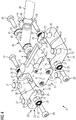
- the Figures 1 to 5 show a measuring arrangement 1 according to an embodiment of the present invention or components thereof.
- the measuring arrangement 1 comprises a test head 2 with an ultrasound probe 3, which in the present case has an essentially cylindrical housing, from the outer surface of which the associated cables 4 are led out.
- the test head 2 comprises a base body 5 which receives the ultrasound probe 2 and which is essentially cuboid is formed and extends in a longitudinal direction L.
- the base body 5 comprises an upper side 6, an underside 7, mutually opposite end faces 8 and 9 and opposing longitudinal sides 10 and 11 which, viewed in cross section, are provided with a uniform curvature.
- a cylindrical through-opening 12 extends substantially in the center from the top 6 to the underside 7, into which, viewed from above, cable receiving grooves 13 open, which extend from the long side 11 in the direction of the through-opening 12.
- the ultrasound probe 3 with the cables 4 held thereon is inserted from above into the through opening 12 and the cable receiving grooves 13 and fixed via a grub screw 14 which is screwed into a threaded through hole 15 which extends from the longitudinal side 10 to the through opening 12.
- the ultrasound probe 3 is positioned within the through opening 12 such that its contact surface 16 extends essentially parallel and at a close distance from a base body support surface 17, which is defined by the underside 7 of the base body 5.
- the distance corresponds to the depth of a contact means receiving recess 18 which surrounds the through opening 12 and thus the ultrasound probe 3 which is inserted therein, the distance or the depth being less than 1 mm.
- two receiving openings 20 are formed in the base body 5, in which magnets 21 are inserted and fastened, in the present case using an adhesive.
- two threaded bores 22 are provided, which are arranged in alignment in the longitudinal direction L.
- the test head 2 further comprises two wing elements 23 and 24 which are pivotally held on the base body 5 and are extend along the long sides 10 and 11 of the base body 5.
- the wing elements 23 and 24 have an essentially mirror-symmetrical construction and each comprise two swivel arms 25 and 26, which encompass the end faces 8 and 9 of the base body 5, each swivel arm 25, 26 being provided with a through hole 27 which is provided with one of the threaded holes 22 aligned, which are provided in the end faces 7, 8 of the base body 4.
- Ball bearings 28 are inserted into the through bore 27, through which fastening screws 29 pass, which in turn are screwed into the threaded bores 22 of the base body 5.
- the wing elements 23 and 24 are pivotally held about pivot axes A 1 and A 2 which extend parallel to one another and in the longitudinal direction L and which extend centrally through the threaded bores 22 of the base body 5 lying opposite one another on the end face.
- the pivot arms 25 of the wing elements 23 and 24 are each connected to one another via synchronization means 30, in the present case in the form of interlocking synchronizing teeth, which leads to pivoting movements of the wing elements 23 and 24 about their pivot axes A 1 and A 2 taking place synchronously.
- the wing elements 23 and 24 each define wing element support surfaces 32 on their undersides 31.
- the wing element support surfaces 32 are each provided with a recess 33 which is elongated, extends in the longitudinal direction L and has an oval shape. In principle, however, other forms of specialization are also possible.
- a grub screw access groove 36 is also formed, which is positioned such that it enables access to the grub screw 14.
- the measuring arrangement 1 further comprises a hollow support rod 38, which is fastened to the end face 9 of the base body 5 via an articulated connection 39, the articulated connection 39 causing the base body 5 and the support rod 38 to pivot relative to a support rod pivot axis A extending in the longitudinal direction L. 3 enables.
- the articulated connection 39 is in the present case in the form of a T-tube and is fastened to the base body 5 using two sealing rings 40, a cover cap 41 which is designed in the manner of a washer and has a collar 42 projecting on one side along its inner circumference, and a fastening screw 39 is screwed into a threaded bore (not shown) formed on the end face 8 of the base body 4.
- the contact means feed opening formed by the contact means channel 19 on the end face 9 of the base body 5 is located between the threaded bore and the sealing ring 40 arranged next to it, so that contact means can get into the contact means receiving recess 18 through the hollow holding rod 38, the articulated connection 39 and the contact means channel 19 .
- the holding rod 38 is pushed over a connecting piece 43 of the articulated connection 39, a further sealing ring 40 being arranged between a ring stop 44 delimiting the connecting piece 43 and the holding rod 38.
- the fastening of the holding rod 38 to the socket 43 is realized using a grub screw 14.
- the dimensions of the base body 5 and the wing elements 23, 24 are selected here in such a way that the maximum height H of the test head 2 in at least one pivoting position of the wing elements 23 and 24, which is shown in FIG Figure 1 shown is not more than 10 mm.
- a syringe 45 is releasably attached to the free end of the holding rod 38 and serves as a contact medium reservoir and supply device.
- the Figure 6 shows two collectors 46 of a heat recovery steam generator of a steam turbine to which a plurality of pipes 47 are connected.
- the tubes 47 are subject to severe corrosion, which is why it is necessary to check the wall thicknesses of the tubes 47 at regular intervals in order to reduce the risk of leakages.
- a problem with the detection of the wall thicknesses of the tubes 47 in the present case is that the tubes 47 can only be reached via the gap 48, which is only about 11 mm wide and is present between the collectors 46, which leads to very poor accessibility. Associated with this is the problem that the tubes 47 are difficult to see.
- the test head 2 is first inserted into the gap 48 using the holding rod 38, which is easily possible due to the low height of the test head 2, and advanced to one of the tubes 47.
- the underside 7 of the base body 5 is then aligned essentially parallel to the pipe surface to be checked and brought into contact with it. Thanks to the magnets 21, both the base body support surface 17 and the wing element support surfaces 32 automatically lie against the surface of the magnetic tube 47, the base body support surface 17 and the wing element support surfaces 32 automatically being optimal due to the synchronous pivoting movement of the wing elements 23 and 24 in order to carry out the wall thickness measurement Position.
- the contact means is then supplied by actuating the syringe 45, whereupon the measurement is carried out in a known manner.
- the signals generated by the ultrasound probe are then fed via the cable 4 to an evaluation device, not shown.
- the test head 2 can simply be moved along the tube 47 to the desired positions.
- the depressions 33 provided on the undersides 31 of the wing elements 23 and 24 have a positive effect in that at least two-point contact between the wing elements 23 and 24 and the pipe surface is always ensured on account of these depressions 33, as long as the shape of the depressions 33 is adapted to the maximum existing curvature.
- the measuring arrangement according to the invention it is possible in summary to also easily detect the wall thicknesses of pipe sections that are difficult to access and / or to see.
Landscapes
- Physics & Mathematics (AREA)
- General Physics & Mathematics (AREA)
- Length Measuring Devices Characterised By Use Of Acoustic Means (AREA)
- Investigating Or Analyzing Materials By The Use Of Ultrasonic Waves (AREA)
Description
- Die vorliegende Erfindung betrifft eine Messanordnung zum Erfassen der Wandstärke eines Rohrs, wie im Anspruch 1 definiert.
- Ferner betrifft die vorliegende Erfindung ein Verfahren zum Erfassen der Wandstärke eines Rohrs unter Verwendung einer solchen Messanordnung, wie im Anspruch 9 definiert.
- Aus dem Stand der Technik ist es grundsätzlich bekannt, die Wandstärke eines Rohrs mittels Ultraschall zu erfassen. In diesem Zusammenhang sind verschiedene Messanordnungen bekannt, die normalerweise einen eine Ultraschallsonde aufnehmenden Basiskörper aufweisen, der an seiner Unterseite eine Basiskörperauflage definiert, die zum Erfassen der Wandstärke eines Rohrs an der Außenseite des Rohrs aufgesetzt wird. Ein solcher Basiskörper mit integriertem Ultraschallsensor wird häufig auch als Prüfkopf bezeichnet. Das Prinzip der Ultraschallmessung ist dem Fachmann bekannt, weshalb hierauf nachfolgend nicht näher eingegangen wird.
- Die
US 2012/0167688 A1 offenbart eine Messanordnung (100) zum Erfassen der Wandstärke eines Rohrs (101), umfassend einen Prüfkopf (Fig. 2 ) mit einem eine Ultraschallsonde (210) aufnehmenden Basiskörper (270), der an seiner Unterseite eine Basiskörperauflagefläche (212) definiert, wobei der Prüfkopf zwei Flügelelemente (220, 230) aufweist, die an ihren Unterseiten jeweils eine Flügelelementauflagefläche (262, 263) definieren (siehe auchFig. 3A und 3B ) und an dem Basiskörper derart schwenkbar um sich im Wesentlichen parallel zueinander und in einer Längsrichtung (Fig. 4 ) erstreckende Schwenkachsen (Fig. 4 ) gehalten sind, dass die Flügelelementauflageflächen aufeinander zu und voneinander weg bewegt werden können (Fig. 4 ). - Die
CN 201053880 Y offenbart eine Messanordnung (Fig. 1 ) zum Erfassen der Wandstärke eines Rohrs (8), umfassend einen Prüfkopf (Fig. 2 ) mit einem eine Messeinrichtung (6) und aufnehmenden Basiskörper (3), der an seiner Unterseite eine Basiskörperauflagefläche (Fig. 1 ) definiert, wobei der Prüfkopf zwei Flügelelemente (1, 2) aufweist, die an ihren Unterseiten jeweils eine Flügelelementauflagefläche (Fig. 1 ) definieren und an dem Basiskörper derart schwenkbar um sich im Wesentlichen parallel zueinander und in einer Längsrichtung (Fig. 1 ,2 ) erstreckende Schwenkachsen gehalten sind, dass die Flügelelementauflageflachen aufeinander zu und voneinander weg bewegt werden können. - Ein Problem beim Erfassen der Wandstärke eines Rohrs unter Verwendung einer Messanordnung der eingangs genannten Art besteht aufgrund der Rundung des Rohrs darin, die Basiskörperauflagefläche lotrecht zur Oberfläche des Rohrs zu halten, was zur Erzielung ordnungsgemäßer Messergebnisse erforderlich ist. Bei gut zugänglichen Rohren lässt sich dieses Problem zwar durch entsprechende Schulung des die Messung durchführenden Personals weitestgehend beheben. Bei der Erfassung der Wandstärke schlecht zugänglicher oder nicht einsehbarer Rohrabschnitte ist jedoch auch geschultem Personal die Durchführung ordnungsgemäßer Wandstärkemessungen kaum möglich.
- Ausgehend von diesem Stand der Technik ist es eine Aufgabe der vorliegenden Erfindung, eine Messanordnung der eingangs genannten Art bereitzustellen, mit der ein ordnungsgemäßes Positionieren der Basiskörperauflagefläche auf der Oberfläche eines zu prüfenden Rohrs auch ungeschultem Personal problemlos möglich ist. Eine weiterführende Aufgabe der vorliegenden Erfindung besteht ferner darin, eine Messanordnung der eingangs genannten Art zu schaffen, mit der sich auch Wandstärken von schlecht zugänglichen und/oder nicht einsehbaren Rohren oder Rohrabschnitten problemlos erfassen lassen.
- Zur Lösung dieser Aufgabe schafft die vorliegende Erfindung eine Messanordnung der eingangs genannten Art, die dadurch gekennzeichnet ist, dass der Prüfkopf zwei Flügelelemente aufweist, die an ihren Unterseiten jeweils eine Flügelelementauflagefläche definieren und an dem Basiskörper derart schwenkbar um sich im Wesentlichen parallel zueinander und in einer Längsrichtung erstreckende Schwenkachsen gehalten sind, dass die Flügelelementauflageflächen aufeinander zu und voneinander weg bewegt werden können, wobei die Flügelelemente derart über Synchronisierungsmittel, insbesondere in Form ineinander greifender Synchronverzahnungen miteinander verbunden sind, dass ihre Schwenkbewegungen um die zugehörigen Schwenkachsen synchron erfolgen. Zur Durchführung einer Wandstärkenmessung eines Rohrs werden sowohl die Basiskörperauflagefläche des Basiskörpers als auch die Flügelelementauflageflächen der beiden Flügelelemente gegen die Oberfläche des Rohrs gedrückt, was dank der synchronisierten Schwenkbewegungen der Flügelelemente um ihre zugehörigen Schwenkachsen dazu führt, dass die Flügelelementauflagefläche automatisch lotrecht auf die Oberfläche des Rohrs aufgesetzt wird. Hieraus resultiert eine sehr genaue und reproduzierbare Positionierung der Ultraschallsonde, ohne dass es besonders geschultem Personal bedarf. Somit wird eine wesentliche Fehlerquelle bei der Wandstärkenmessung eliminiert, was zu sehr zuverlässigen Messergebnissen führt.
- Gemäß einer Ausgestaltung der vorliegenden Erfindung ist die Ultraschallsonde von oben in eine in dem Basiskörper vorgesehene Durchgangsöffnung eingesetzt, wodurch sich insbesondere ein einfacher Aufbau des Basiskörpers ergibt.
- Bevorzugt ist die Messanordnung dadurch gekennzeichnet, dass sich eine Kontaktfläche der Ultraschallsonde im Wesentlichen parallel und in geringem Abstand zur Basiskörperauflagefläche erstreckt, wobei der Abstand insbesondere weniger als 1 mm beträgt, und dass die Basiskörperauflagefläche bevorzugt eine die Kontaktfläche der Ultraschallsonde ringförmig umgebende Kontaktmittelaufnahmevertiefung aufweist, die über einen sich durch den Basiskörper erstreckenden Kontaktmittelkanal mit einer Kontaktmittelzuführöffnung des Basiskörpers verbunden ist, wobei die Tiefe der Kontaktmittelaufnahmevertiefung insbesondere weniger als 1 mm beträgt. Dank der Tatsache, dass die Kontaktfläche der Ultraschallsonde bezogen auf die Basiskörperauflagefläche nach innen versetzt und von einer ringförmig ausgebildeten Kontaktmittelaufnahmevertiefung umgeben ist, kann gewährleistet werden, dass die Kontaktfläche der Ultraschallsonde während der Durchführung einer Wandstärkenmessung ordnungsgemäß mit dem normalerweise eine gelartige Konsistenz aufweisenden Kontaktmittel benetzt wird, wobei nur ein geringer Kontaktmittelverbrauch zu verzeichnen ist. Mit den angegebenen Größenordnungen des Abstands zwischen der Kontaktfläche der Ultraschallsonde und der Basiskörperauflagefläche und/oder der Tiefe der Kontaktmittelaufnahmevertiefung wurden besonders gute Ergebnisse erzielt.
- Vorteilhaft ist an der Basiskörperauflagefläche und/oder an den Flügelelementauflageflächen zumindest ein Magnet angeordnet, bevorzugt jeweils zumindest zwei Magneten, die in der Längsrichtung voneinander beabstandet sind. Dies führt dazu, dass zumindest bei Rohren, die aus einem magnetischen Material hergestellt sind, eine im Wesentlichen automatische Ausrichtung der Basiskörperauflagefläche bzw. der Ultraschallsonde erfolgt, was insbesondere bei Wandstärkenmessungen an schlecht zugänglichen und/oder einsehbaren Rohrabschnitten von großem Vorteil ist.
- Bevorzugt sind die Flügelelementauflageflächen jeweils mit einer Vertiefung versehen, die insbesondere länglich ausgebildet ist und sich in der Längsrichtung erstreckt. Dank derartiger Vertiefungen können auch Wandstärken von Rohrabschnitten, die sich in Längsrichtung des Rohrs betrachtet im Bereich von Rohrkrümmungen befinden, ordnungsgemäß erfasst werden. Die Abmessungen der Vertiefung sind vorteilhaft derart auf die an den Rohren vorhandenen Krümmungsradien angepasst, dass stets zumindest eine Zweipunktauflage der Flügelaufnahmeflächen an der Rohroberfläche gewährleistet ist.
- Vorteilhaft ist die Höhe des Prüfkopfes in zumindest einer Schwenkstellung der Flügelelemente nicht größer als 10 mm, so dass sich der Prüfkopf auch durch schmale Spalte hindurchbewegen lässt.
- Bevorzugt ist an dem Basiskörper eine Haltestange über eine Gelenkverbindung befestigt, wobei die Gelenkverbindung ein relatives Verschwenken des Basiskörpers und der Haltestange um eine sich in der Längsrichtung erstreckende Haltestangenschwenkachse ermöglicht. Mit einer solchen Stange lässt sich der Basiskörper mit den daran gehaltenen Flügelelementen auch an sonst schlecht zugängliche Positionen bewegen.
- Die Haltestange und die Gelenkverbindung definieren vorteilhaft Fluidkanäle, die fluidtechnisch miteinander sowie mit einer an dem Basiskörper angeordneten Kontaktmittelzuführöffnung verbunden sind. Entsprechend kann dem Basiskörper bzw. der Basiskörperauflagefläche über die Haltestange, die Gelenkverbindung und die Kontaktmittelzuführöffnung Kontaktmittel zugeführt werden. Erstreckt sich der Fluidkanal der Haltestange durch die gesamte Haltestange, so kann Kontaktmittel beispielsweise zugeführt werden, indem dieses unter Verwendung einer Spritze in das freie Ende der Haltestange eingespritzt wird.
- Ferner schafft die vorliegende Erfindung ein Verfahren zum Erfassen der Wandstärke eines Rohrs unter Verwendung einer erfindungsgemäßen Messanordnung der zuvor beschriebenen Art, wobei es sich bei dem Rohr insbesondere um ein Rohr eines Abhitzedampferzeugers einer Dampfturbine handelt.
- Weitere Merkmale und Vorteile der vorliegenden Erfindung werden anhand der nachfolgenden Beschreibung einer Ausführungsform einer erfindungsgemäßen Messanordnung unter Bezugnahme auf die beiliegende Zeichnung deutlich. Darin ist
- Figur 1
- eine perspektivische Ansicht eines Prüfkopfes einer Messanordnung gemäß einer ersten Ausführungsform der vorliegenden Erfindung, wobei sich Flügelelemente des Prüfkopfes in einer ersten Schwenkstellung befinden;
- Figur 2
- eine perspektivische Teilansicht des in
Figur 1 gezeigten Prüfkopfes, wobei sich die Flügelelemente in einer zweiten Schwenkstellung befinden; - Figur 3
- eine perspektivische Explosionsansicht des in
Figur 1 gezeigten Prüfkopfes von unten; - Figur 4
- eine perspektivische Explosionsansicht des in
Figur 1 gezeigten Prüfkopfes von oben; - Figur 5
- eine Draufsicht der gesamten Messanordnung und
- Figur 6
- eine schematische Vorderansicht, die Bereiche eines Abhitzedampferzeugers einer Dampfturbine zeigt.
- Die
Figuren 1 bis 5 zeigen eine Messanordnung 1 gemäß einer Ausführungsform der vorliegenden Erfindung bzw. Komponenten derselben. Die Messanordnung 1 umfasst einen Prüfkopf 2 mit einer Ultraschallsonde 3, die vorliegend ein im Wesentlichen zylindrisches Gehäuse aufweist, aus dessen Mantelfläche im oberen Bereich die zugehörigen Kabel 4 herausgeführt sind. Ferner umfasst Prüfkopf 2 einen die Ultraschallsonde 2 aufnehmenden Basiskörper 5, der im Wesentlichen quaderförmig ausgebildet ist und sich in einer Längsrichtung L erstreckt. Der Basiskörper 5 umfasst eine Oberseite 6, eine Unterseite 7, einander gegenüberliegende Stirnseiten 8 und 9 sowie einander gegenüberliegende Längsseiten 10 und 11, die im Querschnitt betrachtet mit einer gleichmäßigen Rundung versehen sind. Im Wesentlichen mittig erstreckt sich von der Oberseite 6 zur Unterseite 7 eine zylindrische Durchgangsöffnung 12, in die von oben betrachtet Kabelaufnahmenuten 13 münden, die sich ausgehend von der Längsseite 11 in Richtung der Durchgangsöffnung 12 erstrecken. In die Durchgangsöffnung 12 und die Kabelaufnahmenuten 13 ist die Ultraschallsonde 3 mit den daran gehaltenen Kabeln 4 von oben eingesetzt und über eine Madenschraube 14 fixiert, die in eine Gewindedurchgangsbohrung 15 geschraubt ist, die sich ausgehend von der Längsseite 10 zur Durchgangsöffnung 12 erstreckt. Die Ultraschallsonde 3 ist innerhalb der Durchgangsöffnung 12 derart positioniert, dass sich ihre Kontaktfläche 16 im Wesentlichen parallel und in engem Abstand zu einer Basiskörperauflagefläche 17 erstreckt, die durch die Unterseite 7 des Basiskörpers 5 definiert ist. Der Abstand entspricht vorliegend der Tiefe einer die Durchgangsöffnung 12 und damit die darin eingesetzte Ultraschallsonde 3 ringförmig umgebenden Kontaktmittelaufnahmevertiefung 18, wobei der Abstand bzw. die Tiefe weniger als 1 mm beträgt. In die Kontaktmittelvertiefung 18 mündet umfangsseitig ein sich durch den Basiskörper 5 erstreckender Kontaktmittelkanal 19, der in etwa mittig an der Stirnseite 9 des Basiskörpers 5 austritt, wo er eine nicht näher dargestellte Kontaktmittelzuführöffnung bildet. An der Basiskörperauflagefläche 17 sind beidseitig der Kontaktmittelvertiefung 18 und mit dieser in Längsrichtung L fluchtend zwei Aufnahmeöffnungen 20 in dem Basiskörper 5 ausgebildet, in denen Magnete 21 eingelassen und befestigt sind, vorliegend unter Verwendung eines Klebstoffes. An den Stirnseiten 8 und 9 sind jeweils zwei Gewindebohrungen 22 vorgesehen, die in Längsrichtung L miteinander fluchtend angeordnet sind. - Der Prüfkopf 2 umfasst ferner zwei Flügelelemente 23 und 24, die schwenkbar an dem Basiskörper 5 gehalten sind und sich entlang der Längsseiten 10 und 11 des Basiskörpers 5 erstrecken. Die Flügelelemente 23 und 24 weisen einen im Wesentlichen spiegelsymmetrischen Aufbau auf und umfassen jeweils zwei Schwenkarme 25 und 26, welche die Stirnseiten 8 und 9 des Basiskörpers 5 umgreifen, wobei jeder Schwenkarm 25, 26 mit einer Durchgangsbohrung 27 versehen ist, die mit einer der Gewindebohrungen 22 fluchtet, die in den Stirnseiten 7, 8 des Basiskörpers 4 vorgesehen sind. In die Durchgangsbohrung 27 sind jeweils Kugellager 28 eingesetzt, die von Befestigungsschrauben 29 durchgriffen werden, die wiederum in die Gewindebohrungen 22 des Basiskörpers 5 eingeschraubt sind. Somit sind die Flügelelemente 23 und 24 schwenkbar um sich parallel zueinander und in Längsrichtung L erstreckende Schwenkachsen A1 und A2 gehalten, die sich mittig durch die stirnseitig einander gegenüberliegenden Gewindebohrungen 22 des Basiskörpers 5 erstrecken. Die Schwenkarme 25 der Flügelelemente 23 und 24 sind jeweils über Synchronisierungsmittel 30, vorliegend in Form ineinandergreifender Synchronverzahnungen miteinander verbunden, was dazu führt, dass Schwenkbewegungen der Flügelelemente 23 und 24 um ihre Schwenkachsen A1 und A2 jeweils synchron erfolgen. Die Flügelelemente 23 und 24 definieren an ihren Unterseiten 31 jeweils Flügelelementauflageflächen 32. Vorliegend sind die Flügelelementauflageflächen 32 jeweils mit einer Vertiefung 33 versehen, die länglich ausgebildet ist, sich in der Längsrichtung L erstreckt und eine ovale Form aufweist. Grundsätzlich sind allerdings auch andere Vertiefungsformen möglich. An der Oberseite 34 jedes Flügelelementes 23, 24 sind zwei Aufnahmeöffnungen 35 ausgebildet, die kurz vor der Unterseite 31 der Flügelelemente 23, 24 enden, wobei die Aufnahmeöffnung 35 in Längsrichtung L im Wesentlichen auf einer Linie angeordnet sind. In den Aufnahmeöffnungen 35 sind Magneten 21 eingelassen und befestigt, vorliegend unter Verwendung eines Klebstoffes. An der Oberseite 34 des Flügelelementes 23, das der Madenschraube 13 zugewandt ist, ist ferner eine Madenschraubenzugangsnut 36 ausgebildet, die derart positioniert ist, dass sie den Zugang zur Madenschraube 14 ermöglicht. An der Oberseite 34 des anderen Flügelelementes 24 sind Nuten 37 ausgebildet, die mit den Kabelaufnahmenuten 13 des Basiskörpers 5 fluchten.
- Die Messanordnung 1 umfasst ferner eine hohl ausgebildete Haltestange 38, die über eine Gelenkverbindung 39 an der Stirnseite 9 des Basiskörpers 5 befestigt ist, wobei die Gelenkverbindung 39 ein relatives Verschwenken des Basiskörpers 5 und der Haltestange 38 um eine sich in der Längsrichtung L erstreckende Haltestangenschwenkachse A3 ermöglicht. Die Gelenkverbindung 39 ist vorliegend als T-Rohr ausgebildet und unter Verwendung zweier Dichtringe 40, einer Abdeckkappe 41, die nach Art einer Unterlegscheibe ausgebildet ist und entlang ihres Innenumfangs einen einseitig vorstehenden Bund 42 aufweist, und einer Befestigungsschraube 39 an dem Basiskörper 5 befestigt, die in eine nicht dargestellte, an der Stirnseite 8 des Basiskörpers 4 ausgebildete Gewindebohrung geschraubt ist. Die durch den Kontaktmittelkanal 19 an der Stirnseite 9 des Basiskörpers 5 gebildete Kontaktmittelzuführöffnung befindet sich dabei zwischen der Gewindebohrung und dem benachbart angeordneten Dichtring 40, so dass Kontaktmittel durch die hohl ausgebildete Haltestange 38, die Gelenkverbindung 39 und den Kontaktmittelkanal 19 in die Kontaktmittelaufnahmevertiefung 18 gelangen kann. Die Haltestange 38 ist über einen Stutzen 43 der Gelenkverbindung 39 geschoben, wobei ein weiterer Dichtring 40 zwischen einem den Stutzen 43 begrenzenden Ringanschlag 44 und der Haltestange 38 angeordnet ist. die Befestigung der Haltestange 38 an dem Stutzen 43 ist über eine Madenschraube 14 realisiert.
- Die Abmessungen des Basiskörpers 5 und der Flügelelemente 23, 24 sind vorliegend derart gewählt, dass die maximale Höhe H des Prüfkopfes 2 in zumindest einer Schwenkstellung der Flügelelemente 23 und 24, die vorliegend in
Figur 1 gezeigt ist, nicht mehr als 10 mm beträgt. Gleiches gilt für die Abmessungen der Gelenkverbindung 39 ebenso wie für den Durchmesser D der Haltestange 38, so dass diese nicht über den Prüfkopf 2 vorstehen, wenn die Haltestange 38 inFigur 1 parallel zu dem Basiskörper 5 und den Flügelelementen 23, 24 angeordnet wird. - Am freien Ende der Haltestange 38 ist vorliegend lösbar eine Spritze 45 befestigt, die als Kontaktmittelreservoir- und -zuführeinrichtung dient.
- Die
Figur 6 zeigt zwei Sammler 46 eines Abhitzedampferzeugers einer Dampfturbine, an die eine Vielzahl von Rohren 47 angeschlossen ist. Die Rohre 47 sind einer starken Korrosion ausgesetzt, weshalb es erforderlich ist, in regelmäßigen Abständen die Wandstärken der Rohre 47 zu prüfen, um die Gefahr von Leckagen zu verringern. Ein Problem bei der Erfassung der Wandstärken der Rohre 47 besteht im vorliegenden Fall darin, dass die Rohre 47 nur über den zwischen den Sammlern 46 vorhandenen, nur etwa 11 mm breiten Spalt 48 zu erreichen sind, was zu einer sehr schlechten Zugänglichkeit führt. Damit einhergehend besteht das Problem, dass die Rohre 47 schlecht einsehbar sind. - Zur Durchführung einer Wandstärkenmessung eines oder mehrerer der Rohre 47 wird der Prüfkopf 2 unter Verwendung der Haltestange 38 zunächst in den Spalt 48 eingeführt, was aufgrund der geringen Höhe des Prüfkopfes 2 problemlos möglich ist, und bis zu einem der Rohre 47 vorgeschoben. Anschließend wird die Unterseite 7 des Basiskörpers 5 im Wesentlichen parallel zu der zu überprüfenden Rohroberfläche ausgerichtet und mit dieser in Kontakt gebracht. Dank der Magneten 21 legen sich sowohl die Basiskörperauflagefläche 17 als auch die Flügelelementauflageflächen 32 automatisch an der Oberfläche des magnetischen Rohrs 47 an, wobei die Basiskörperauflagefläche 17 und die Flügelelementauflageflächen 32 aufgrund der synchronen Schwenkbewegung der Flügelelemente 23 und 24 automatisch in eine zur Durchführung der Wandstärkenmessung optimale Position ausgerichtet werden. Anschließend wird das Kontaktmittel durch Betätigen der Spritze 45 zugeführt, woraufhin in bekannter Weise die Messung erfolgt. Die von der Ultraschallsonde erzeugten Signale werden dann über die Kabel 4 einer nicht näher dargestellten Auswerteeinrichtung zugeführt. Zur Durchführung weiterer Messungen an demselben Rohr 47 kann der Prüfkopf 2 einfach entlang des Rohrs 47 zu den gewünschten Positionen verschoben werden. Im Bereich einer Rohrkrümmung wirken sich die an den Unterseiten 31 der Flügelelemente 23 und 24 vorgesehenen Vertiefungen 33 dahingehend positiv aus, dass aufgrund dieser Vertiefungen 33 stets zumindest ein Zweipunktkontakt zwischen den Flügelelementen 23 und 24 und der Rohroberfläche gewährleistet ist, solange die Form der Vertiefungen 33 an die maximal vorhandene Krümmung angepasst ist.
- Dank der erfindungsgemäßen Messanordnung ist es zusammenfassend möglich, auch die Wandstärken schlecht zugänglicher und/oder einsehbarer Rohrabschnitte problemlos zu erfassen.
- Obwohl die Erfindung im Detail durch das bevorzugte Ausführungsbeispiel näher illustriert und beschrieben wurde, so ist die Erfindung nicht durch die offenbarten Beispiele eingeschränkt und andere Variationen können vom Fachmann hieraus abgeleitet werden, ohne den Schutzumfang der Erfindung zu verlassen.
Claims (9)
- Messanordnung (1) zum Erfassen der Wandstärke eines Rohrs (47), umfassend einen Prüfkopf (2) mit einer Ultraschallsonde (3) und einem die Ultraschallsonde (3) aufnehmenden Basiskörper (5), der an seiner Unterseite (7) eine Basiskörperauflagefläche (17) definiert, dadurch gekennzeichnet, dass
der Prüfkopf (2) zwei Flügelelemente (23, 24) aufweist, die an ihren Unterseiten (31) jeweils eine Flügelelementauflagefläche (32) definieren und an dem Basiskörper (5) derart schwenkbar um sich im Wesentlichen parallel zueinander und in einer Längsrichtung (L) erstreckende Schwenkachsen (A1, A2) gehalten sind, dass die Flügelelementauflageflächen (32) aufeinander zu und voneinander weg bewegt werden können, dadurch gekennzeichnet, dass die Flügelelemente (23, 24) derart über Synchronisierungsmittel (30), insbesondere in Form ineinander greifender Synchronverzahnungen miteinander verbunden sind, dass ihre Schwenkbewegungen um die zugehörigen Schwenkachsen (A1, A2) synchron erfolgen. - Messanordnung (1) nach Anspruch 1,
dadurch gekennzeichnet, dass
die Ultraschallsonde (3) von oben in eine in dem Basiskörper (5) vorgesehene Durchgangsöffnung (12) eingesetzt ist. - Messanordnung (1) nach Anspruch 1 oder 2,
dadurch gekennzeichnet, dass
sich eine Kontaktfläche (16) der Ultraschallsonde (3) im Wesentlichen parallel und in geringem Abstand zur Basiskörperauflagefläche (17) erstreckt,
wobei der Abstand insbesondere weniger als 1 mm beträgt, und
dass die Basiskörperauflagefläche (17) bevorzugt einen die Kontaktfläche (16) der Ultraschallsonde (3) ringförmig umgebende Kontaktmittelaufnahmevertiefung (18) aufweist, die über einen sich durch den Basiskörper (5) erstreckenden Kontaktmittelkanal (19) mit einer Kontaktmittelzuführöffnung des Basiskörpers (5) verbunden ist,
wobei die Tiefe der Kontaktmittelaufnahmevertiefung (18) insbesondere weniger als 1 mm beträgt. - Messanordnung (1) nach einem der vorhergehenden Ansprüche,
dadurch gekennzeichnet, dass
an der Basiskörperauflagefläche (17) und/oder an den Flügelelementauflageflächen (32) zumindest ein Magnet (21) angeordnet ist,
bevorzugt jeweils zumindest zwei Magneten (21), die in der Längsrichtung voneinander beabstandet sind. - Messanordnung (1) nach einem der vorhergehenden Ansprüche,
dadurch gekennzeichnet, dass
die Flügelelementauflageflächen (32) jeweils mit einer Vertiefung (33) versehen sind, die insbesondere länglich ausgebildet ist und sich in der Längsrichtung (L) erstreckt. - Messanordnung (1) nach einem der vorhergehenden Ansprüche,
dadurch gekennzeichnet, dass
die Höhe (H) des Prüfkopfes (2) in zumindest einer Schwenkstellung der Flügelelemente nicht größer als 10 mm ist. - Messanordnung (1) nach einem der vorhergehenden Ansprüche,
dadurch gekennzeichnet, dass
an dem Basiskörper (5) eine Haltestange (38) über eine Gelenkverbindung (39) befestigt ist,
wobei die Gelenkverbindung (39) ein relatives Verschwenken des Basiskörpers (5) und der Haltestange (38) um eine sich in der Längsrichtung (L) erstreckende Haltestangenschwenkachse (A3) ermöglicht. - Messanordnung (1) nach Anspruch 3 und 7,
dadurch gekennzeichnet, dass
die Haltestange (38) und die Gelenkverbindung (39) Fluidkanäle definieren, die fluidtechnisch miteinander sowie mit der Kontaktmittelzuführöffnung verbunden sind. - Verfahren zum Erfassen der Wandstärke eines Rohrs (47) unter Verwendung einer Messanordnung (1) nach einem der vorhergehenden Ansprüche,
wobei es sich bei dem Rohr (47) insbesondere um ein Rohr eines Abhitzedampferzeugers einer Dampfturbine handelt.
Applications Claiming Priority (2)
| Application Number | Priority Date | Filing Date | Title |
|---|---|---|---|
| DE102016223807.8A DE102016223807A1 (de) | 2016-11-30 | 2016-11-30 | Messanordnung zum Erfassen der Wandstärke eines Rohrs |
| PCT/EP2017/078067 WO2018099682A1 (de) | 2016-11-30 | 2017-11-02 | Ultraschallmessanordnung und verfahren zum erfassen der wandstärke eines rohrs |
Publications (2)
| Publication Number | Publication Date |
|---|---|
| EP3519765A1 EP3519765A1 (de) | 2019-08-07 |
| EP3519765B1 true EP3519765B1 (de) | 2020-07-08 |
Family
ID=60387993
Family Applications (1)
| Application Number | Title | Priority Date | Filing Date |
|---|---|---|---|
| EP17800736.5A Active EP3519765B1 (de) | 2016-11-30 | 2017-11-02 | Ultraschallmessanordnung und verfahren zum erfassen der wandstärke eines rohrs |
Country Status (5)
| Country | Link |
|---|---|
| US (1) | US10962359B2 (de) |
| EP (1) | EP3519765B1 (de) |
| DE (1) | DE102016223807A1 (de) |
| ES (1) | ES2823055T3 (de) |
| WO (1) | WO2018099682A1 (de) |
Families Citing this family (1)
| Publication number | Priority date | Publication date | Assignee | Title |
|---|---|---|---|---|
| US11578971B2 (en) * | 2021-02-12 | 2023-02-14 | Holloway Ndt & Engineering Inc. | Ultrasonic testing using a phased array |
Family Cites Families (12)
| Publication number | Priority date | Publication date | Assignee | Title |
|---|---|---|---|---|
| BE530247A (de) * | 1953-07-18 | |||
| US3924453A (en) | 1973-05-04 | 1975-12-09 | United States Steel Corp | Ultrasonic testing of tubing employing a spiral wave generator |
| JP2001194352A (ja) * | 2000-01-05 | 2001-07-19 | Kansai X Sen Kk | 管状部材の超音波検査装置 |
| US7201055B1 (en) | 2005-10-10 | 2007-04-10 | General Electric Company | Ultrasonic miniature air gap inspection crawler |
| JP4670599B2 (ja) * | 2005-11-09 | 2011-04-13 | Jfeスチール株式会社 | 検査機器用自走台車 |
| CN201053880Y (zh) * | 2007-07-12 | 2008-04-30 | 西安华舜测量设备有限责任公司 | 一种外置式储罐或管道固定测量设备的装置 |
| US7877888B2 (en) | 2007-10-25 | 2011-02-01 | General Electric Company | System and method for measuring installation dimensions for flow measurement system |
| JP4524764B2 (ja) * | 2008-03-31 | 2010-08-18 | 住友金属工業株式会社 | 超音波探傷方法及び装置 |
| JP5496065B2 (ja) * | 2010-11-11 | 2014-05-21 | 株式会社トクヤマ | 歪測定装置 |
| US8365601B2 (en) * | 2011-01-04 | 2013-02-05 | Saudi Arabian Oil Company | High precision corrosion monitoring sensor assembly and system |
| EP2691736B1 (de) * | 2011-03-31 | 2016-03-30 | Atomic Energy of Canada Limited | Profilierwerkzeug zur bestimmung einer materialdicke für prüfstellen mit komplexer topographie |
| KR101483551B1 (ko) * | 2013-09-09 | 2015-01-16 | 한국전력공사 | 센서부착장치 |
-
2016
- 2016-11-30 DE DE102016223807.8A patent/DE102016223807A1/de not_active Withdrawn
-
2017
- 2017-11-02 US US16/462,953 patent/US10962359B2/en active Active
- 2017-11-02 ES ES17800736T patent/ES2823055T3/es active Active
- 2017-11-02 EP EP17800736.5A patent/EP3519765B1/de active Active
- 2017-11-02 WO PCT/EP2017/078067 patent/WO2018099682A1/de not_active Ceased
Non-Patent Citations (1)
| Title |
|---|
| None * |
Also Published As
| Publication number | Publication date |
|---|---|
| EP3519765A1 (de) | 2019-08-07 |
| ES2823055T3 (es) | 2021-05-07 |
| US10962359B2 (en) | 2021-03-30 |
| US20190277631A1 (en) | 2019-09-12 |
| WO2018099682A1 (de) | 2018-06-07 |
| DE102016223807A1 (de) | 2018-05-30 |
Similar Documents
| Publication | Publication Date | Title |
|---|---|---|
| EP2568263B1 (de) | Portables Ultraschallduchflussmesssystem | |
| DE2121070A1 (de) | Maschine mit verbessertem Arbeits kopf zur Querfuhrung bei Werkstucken mit gekrümmten Oberflächen | |
| DE102016208949A1 (de) | Vorrichtung zum Vermessen der Geometrie der Innenwand von Bohrungen und Verfahren | |
| DE2439662A1 (de) | Vorrichtung zum zerstoerungsfreien pruefen von metallischen rohlingen auf oberflaechenfehler | |
| DE3026352A1 (de) | Messinstrument zur ueberpruefung der linearen abmessungen von mechanischen teilen | |
| CH710485A2 (de) | Sonden für ein Inspektionssystem für ein im wesentlichen rundes Loch. | |
| DE3102019C2 (de) | Gegenstützvorrichtung für das Stumpfverschweißen von zwei Rohren | |
| DE3017193A1 (de) | Einbauarmatur fuer messwertaufnehmer an schwer zugaenglich messstellen in maschinen | |
| DE2620334A1 (de) | Selbsttaetig gefuehrter axialer rohrkompensator | |
| CH636193A5 (de) | Anzeigegeraet mit vorrichtung zum pruefen und messen von bohrungen. | |
| CH616524A5 (en) | Method and device for testing the nozzle areas of a reactor pressure vessel by means of ultrasonic waves. | |
| DE69214539T2 (de) | Verfahren und Vorrichtung zur Überprüfung des Oberflächenzustands eines Bohrlochs | |
| DE3202883C2 (de) | Bewegungseinrichtung zum Antrieb einer Sonde | |
| EP0617253B1 (de) | Messvorrichtung zum Vermessen der Form von Zylindern | |
| DE19913659B4 (de) | Positionserfassungsgerät | |
| DE102016223807A1 (de) | Messanordnung zum Erfassen der Wandstärke eines Rohrs | |
| DE2627090A1 (de) | Vorrichtung zur messung von konzentrizitaetsfehlern zweier rotationsflaechen | |
| DE2811453A1 (de) | Verbindungsvorrichtung | |
| DE4326406C1 (de) | Verzahnungsprüfgerät | |
| WO2017140901A1 (de) | Verbindungselement | |
| DE8816434U1 (de) | Wanddickenmeßvorrichtung für Rohre, Kabelummantelungen u.dgl., insbesondere aus extrudiertem Kunststoff | |
| EP2050920A2 (de) | Verfahren und Vorrichtung zum Einziehen eines aus Kurzrohren zusammengesetzten Rohrstranges in einen Bohrkanal | |
| DE3504522C2 (de) | Verfahren und Einrichtung zum Ultraschallprüfen von Schrauben auf Anrisse | |
| DE10112857C2 (de) | Spaltmaß-Meßvorrichtung für ineinandergesteckte Hohlkörper | |
| DE3445587A1 (de) | Vorrichtung zur messung mechanischer eigenschaften von lebender haut |
Legal Events
| Date | Code | Title | Description |
|---|---|---|---|
| STAA | Information on the status of an ep patent application or granted ep patent |
Free format text: STATUS: UNKNOWN |
|
| STAA | Information on the status of an ep patent application or granted ep patent |
Free format text: STATUS: THE INTERNATIONAL PUBLICATION HAS BEEN MADE |
|
| PUAI | Public reference made under article 153(3) epc to a published international application that has entered the european phase |
Free format text: ORIGINAL CODE: 0009012 |
|
| STAA | Information on the status of an ep patent application or granted ep patent |
Free format text: STATUS: REQUEST FOR EXAMINATION WAS MADE |
|
| 17P | Request for examination filed |
Effective date: 20190430 |
|
| AK | Designated contracting states |
Kind code of ref document: A1 Designated state(s): AL AT BE BG CH CY CZ DE DK EE ES FI FR GB GR HR HU IE IS IT LI LT LU LV MC MK MT NL NO PL PT RO RS SE SI SK SM TR |
|
| AX | Request for extension of the european patent |
Extension state: BA ME |
|
| GRAP | Despatch of communication of intention to grant a patent |
Free format text: ORIGINAL CODE: EPIDOSNIGR1 |
|
| STAA | Information on the status of an ep patent application or granted ep patent |
Free format text: STATUS: GRANT OF PATENT IS INTENDED |
|
| DAV | Request for validation of the european patent (deleted) | ||
| DAX | Request for extension of the european patent (deleted) | ||
| INTG | Intention to grant announced |
Effective date: 20200228 |
|
| GRAS | Grant fee paid |
Free format text: ORIGINAL CODE: EPIDOSNIGR3 |
|
| GRAA | (expected) grant |
Free format text: ORIGINAL CODE: 0009210 |
|
| STAA | Information on the status of an ep patent application or granted ep patent |
Free format text: STATUS: THE PATENT HAS BEEN GRANTED |
|
| AK | Designated contracting states |
Kind code of ref document: B1 Designated state(s): AL AT BE BG CH CY CZ DE DK EE ES FI FR GB GR HR HU IE IS IT LI LT LU LV MC MK MT NL NO PL PT RO RS SE SI SK SM TR |
|
| REG | Reference to a national code |
Ref country code: CH Ref legal event code: EP Ref country code: AT Ref legal event code: REF Ref document number: 1288924 Country of ref document: AT Kind code of ref document: T Effective date: 20200715 |
|
| REG | Reference to a national code |
Ref country code: DE Ref legal event code: R096 Ref document number: 502017006138 Country of ref document: DE |
|
| REG | Reference to a national code |
Ref country code: IE Ref legal event code: FG4D Free format text: LANGUAGE OF EP DOCUMENT: GERMAN |
|
| REG | Reference to a national code |
Ref country code: CH Ref legal event code: NV Representative=s name: SIEMENS SCHWEIZ AG, CH |
|
| REG | Reference to a national code |
Ref country code: NL Ref legal event code: FP |
|
| REG | Reference to a national code |
Ref country code: LT Ref legal event code: MG4D |
|
| REG | Reference to a national code |
Ref country code: DE Ref legal event code: R081 Ref document number: 502017006138 Country of ref document: DE Owner name: SIEMENS ENERGY GLOBAL GMBH & CO. KG, DE Free format text: FORMER OWNER: SIEMENS AKTIENGESELLSCHAFT, 80333 MUENCHEN, DE |
|
| RAP2 | Party data changed (patent owner data changed or rights of a patent transferred) |
Owner name: SIEMENS ENERGY GLOBAL GMBH & CO. KG |
|
| PG25 | Lapsed in a contracting state [announced via postgrant information from national office to epo] |
Ref country code: PT Free format text: LAPSE BECAUSE OF FAILURE TO SUBMIT A TRANSLATION OF THE DESCRIPTION OR TO PAY THE FEE WITHIN THE PRESCRIBED TIME-LIMIT Effective date: 20201109 Ref country code: HR Free format text: LAPSE BECAUSE OF FAILURE TO SUBMIT A TRANSLATION OF THE DESCRIPTION OR TO PAY THE FEE WITHIN THE PRESCRIBED TIME-LIMIT Effective date: 20200708 Ref country code: LT Free format text: LAPSE BECAUSE OF FAILURE TO SUBMIT A TRANSLATION OF THE DESCRIPTION OR TO PAY THE FEE WITHIN THE PRESCRIBED TIME-LIMIT Effective date: 20200708 Ref country code: BG Free format text: LAPSE BECAUSE OF FAILURE TO SUBMIT A TRANSLATION OF THE DESCRIPTION OR TO PAY THE FEE WITHIN THE PRESCRIBED TIME-LIMIT Effective date: 20201008 Ref country code: SE Free format text: LAPSE BECAUSE OF FAILURE TO SUBMIT A TRANSLATION OF THE DESCRIPTION OR TO PAY THE FEE WITHIN THE PRESCRIBED TIME-LIMIT Effective date: 20200708 Ref country code: FI Free format text: LAPSE BECAUSE OF FAILURE TO SUBMIT A TRANSLATION OF THE DESCRIPTION OR TO PAY THE FEE WITHIN THE PRESCRIBED TIME-LIMIT Effective date: 20200708 Ref country code: GR Free format text: LAPSE BECAUSE OF FAILURE TO SUBMIT A TRANSLATION OF THE DESCRIPTION OR TO PAY THE FEE WITHIN THE PRESCRIBED TIME-LIMIT Effective date: 20201009 Ref country code: NO Free format text: LAPSE BECAUSE OF FAILURE TO SUBMIT A TRANSLATION OF THE DESCRIPTION OR TO PAY THE FEE WITHIN THE PRESCRIBED TIME-LIMIT Effective date: 20201008 |
|
| PG25 | Lapsed in a contracting state [announced via postgrant information from national office to epo] |
Ref country code: LV Free format text: LAPSE BECAUSE OF FAILURE TO SUBMIT A TRANSLATION OF THE DESCRIPTION OR TO PAY THE FEE WITHIN THE PRESCRIBED TIME-LIMIT Effective date: 20200708 Ref country code: RS Free format text: LAPSE BECAUSE OF FAILURE TO SUBMIT A TRANSLATION OF THE DESCRIPTION OR TO PAY THE FEE WITHIN THE PRESCRIBED TIME-LIMIT Effective date: 20200708 Ref country code: PL Free format text: LAPSE BECAUSE OF FAILURE TO SUBMIT A TRANSLATION OF THE DESCRIPTION OR TO PAY THE FEE WITHIN THE PRESCRIBED TIME-LIMIT Effective date: 20200708 Ref country code: IS Free format text: LAPSE BECAUSE OF FAILURE TO SUBMIT A TRANSLATION OF THE DESCRIPTION OR TO PAY THE FEE WITHIN THE PRESCRIBED TIME-LIMIT Effective date: 20201108 |
|
| REG | Reference to a national code |
Ref country code: DE Ref legal event code: R097 Ref document number: 502017006138 Country of ref document: DE |
|
| PG25 | Lapsed in a contracting state [announced via postgrant information from national office to epo] |
Ref country code: DK Free format text: LAPSE BECAUSE OF FAILURE TO SUBMIT A TRANSLATION OF THE DESCRIPTION OR TO PAY THE FEE WITHIN THE PRESCRIBED TIME-LIMIT Effective date: 20200708 Ref country code: CZ Free format text: LAPSE BECAUSE OF FAILURE TO SUBMIT A TRANSLATION OF THE DESCRIPTION OR TO PAY THE FEE WITHIN THE PRESCRIBED TIME-LIMIT Effective date: 20200708 Ref country code: RO Free format text: LAPSE BECAUSE OF FAILURE TO SUBMIT A TRANSLATION OF THE DESCRIPTION OR TO PAY THE FEE WITHIN THE PRESCRIBED TIME-LIMIT Effective date: 20200708 Ref country code: EE Free format text: LAPSE BECAUSE OF FAILURE TO SUBMIT A TRANSLATION OF THE DESCRIPTION OR TO PAY THE FEE WITHIN THE PRESCRIBED TIME-LIMIT Effective date: 20200708 Ref country code: SM Free format text: LAPSE BECAUSE OF FAILURE TO SUBMIT A TRANSLATION OF THE DESCRIPTION OR TO PAY THE FEE WITHIN THE PRESCRIBED TIME-LIMIT Effective date: 20200708 |
|
| REG | Reference to a national code |
Ref country code: ES Ref legal event code: FG2A Ref document number: 2823055 Country of ref document: ES Kind code of ref document: T3 Effective date: 20210507 |
|
| PLBE | No opposition filed within time limit |
Free format text: ORIGINAL CODE: 0009261 |
|
| STAA | Information on the status of an ep patent application or granted ep patent |
Free format text: STATUS: NO OPPOSITION FILED WITHIN TIME LIMIT |
|
| PG25 | Lapsed in a contracting state [announced via postgrant information from national office to epo] |
Ref country code: AL Free format text: LAPSE BECAUSE OF FAILURE TO SUBMIT A TRANSLATION OF THE DESCRIPTION OR TO PAY THE FEE WITHIN THE PRESCRIBED TIME-LIMIT Effective date: 20200708 |
|
| 26N | No opposition filed |
Effective date: 20210409 |
|
| PG25 | Lapsed in a contracting state [announced via postgrant information from national office to epo] |
Ref country code: SK Free format text: LAPSE BECAUSE OF FAILURE TO SUBMIT A TRANSLATION OF THE DESCRIPTION OR TO PAY THE FEE WITHIN THE PRESCRIBED TIME-LIMIT Effective date: 20200708 Ref country code: MC Free format text: LAPSE BECAUSE OF FAILURE TO SUBMIT A TRANSLATION OF THE DESCRIPTION OR TO PAY THE FEE WITHIN THE PRESCRIBED TIME-LIMIT Effective date: 20200708 |
|
| PG25 | Lapsed in a contracting state [announced via postgrant information from national office to epo] |
Ref country code: LU Free format text: LAPSE BECAUSE OF NON-PAYMENT OF DUE FEES Effective date: 20201102 |
|
| REG | Reference to a national code |
Ref country code: BE Ref legal event code: MM Effective date: 20201130 |
|
| PG25 | Lapsed in a contracting state [announced via postgrant information from national office to epo] |
Ref country code: SI Free format text: LAPSE BECAUSE OF FAILURE TO SUBMIT A TRANSLATION OF THE DESCRIPTION OR TO PAY THE FEE WITHIN THE PRESCRIBED TIME-LIMIT Effective date: 20200708 |
|
| PG25 | Lapsed in a contracting state [announced via postgrant information from national office to epo] |
Ref country code: IE Free format text: LAPSE BECAUSE OF NON-PAYMENT OF DUE FEES Effective date: 20201102 |
|
| REG | Reference to a national code |
Ref country code: GB Ref legal event code: 732E Free format text: REGISTERED BETWEEN 20211202 AND 20211209 |
|
| PGFP | Annual fee paid to national office [announced via postgrant information from national office to epo] |
Ref country code: CH Payment date: 20220209 Year of fee payment: 5 |
|
| PG25 | Lapsed in a contracting state [announced via postgrant information from national office to epo] |
Ref country code: MT Free format text: LAPSE BECAUSE OF FAILURE TO SUBMIT A TRANSLATION OF THE DESCRIPTION OR TO PAY THE FEE WITHIN THE PRESCRIBED TIME-LIMIT Effective date: 20200708 Ref country code: CY Free format text: LAPSE BECAUSE OF FAILURE TO SUBMIT A TRANSLATION OF THE DESCRIPTION OR TO PAY THE FEE WITHIN THE PRESCRIBED TIME-LIMIT Effective date: 20200708 |
|
| PG25 | Lapsed in a contracting state [announced via postgrant information from national office to epo] |
Ref country code: MK Free format text: LAPSE BECAUSE OF FAILURE TO SUBMIT A TRANSLATION OF THE DESCRIPTION OR TO PAY THE FEE WITHIN THE PRESCRIBED TIME-LIMIT Effective date: 20200708 |
|
| PG25 | Lapsed in a contracting state [announced via postgrant information from national office to epo] |
Ref country code: BE Free format text: LAPSE BECAUSE OF NON-PAYMENT OF DUE FEES Effective date: 20201130 |
|
| REG | Reference to a national code |
Ref country code: NL Ref legal event code: PD Owner name: SIEMENS ENERGY GLOBAL GMBH & CO. KG; DE Free format text: DETAILS ASSIGNMENT: CHANGE OF OWNER(S), ASSIGNMENT; FORMER OWNER NAME: SIEMENS AKTIENGESELLSCHAFT Effective date: 20230125 |
|
| REG | Reference to a national code |
Ref country code: CH Ref legal event code: PL |
|
| PG25 | Lapsed in a contracting state [announced via postgrant information from national office to epo] |
Ref country code: LI Free format text: LAPSE BECAUSE OF NON-PAYMENT OF DUE FEES Effective date: 20221130 Ref country code: CH Free format text: LAPSE BECAUSE OF NON-PAYMENT OF DUE FEES Effective date: 20221130 |
|
| REG | Reference to a national code |
Ref country code: AT Ref legal event code: MM01 Ref document number: 1288924 Country of ref document: AT Kind code of ref document: T Effective date: 20221102 |
|
| PG25 | Lapsed in a contracting state [announced via postgrant information from national office to epo] |
Ref country code: AT Free format text: LAPSE BECAUSE OF NON-PAYMENT OF DUE FEES Effective date: 20221102 |
|
| PGFP | Annual fee paid to national office [announced via postgrant information from national office to epo] |
Ref country code: NL Payment date: 20251124 Year of fee payment: 9 |
|
| PGFP | Annual fee paid to national office [announced via postgrant information from national office to epo] |
Ref country code: DE Payment date: 20251126 Year of fee payment: 9 |
|
| PGFP | Annual fee paid to national office [announced via postgrant information from national office to epo] |
Ref country code: GB Payment date: 20251125 Year of fee payment: 9 |
|
| PGFP | Annual fee paid to national office [announced via postgrant information from national office to epo] |
Ref country code: IT Payment date: 20251121 Year of fee payment: 9 |
|
| PGFP | Annual fee paid to national office [announced via postgrant information from national office to epo] |
Ref country code: FR Payment date: 20251124 Year of fee payment: 9 |
|
| PGFP | Annual fee paid to national office [announced via postgrant information from national office to epo] |
Ref country code: TR Payment date: 20251014 Year of fee payment: 9 |
|
| PGFP | Annual fee paid to national office [announced via postgrant information from national office to epo] |
Ref country code: ES Payment date: 20251209 Year of fee payment: 9 |