EP3519657B1 - Verstellbares stopperelement mit verbesserter fixierung und/oder einstellbarkeit - Google Patents
Verstellbares stopperelement mit verbesserter fixierung und/oder einstellbarkeit Download PDFInfo
- Publication number
- EP3519657B1 EP3519657B1 EP17772293.1A EP17772293A EP3519657B1 EP 3519657 B1 EP3519657 B1 EP 3519657B1 EP 17772293 A EP17772293 A EP 17772293A EP 3519657 B1 EP3519657 B1 EP 3519657B1
- Authority
- EP
- European Patent Office
- Prior art keywords
- base part
- car body
- expansion
- hook elements
- opening
- Prior art date
- Legal status (The legal status is an assumption and is not a legal conclusion. Google has not performed a legal analysis and makes no representation as to the accuracy of the status listed.)
- Active
Links
Images


Classifications
-
- E—FIXED CONSTRUCTIONS
- E05—LOCKS; KEYS; WINDOW OR DOOR FITTINGS; SAFES
- E05F—DEVICES FOR MOVING WINGS INTO OPEN OR CLOSED POSITION; CHECKS FOR WINGS; WING FITTINGS NOT OTHERWISE PROVIDED FOR, CONCERNED WITH THE FUNCTIONING OF THE WING
- E05F5/00—Braking devices, e.g. checks; Stops; Buffers
- E05F5/02—Braking devices, e.g. checks; Stops; Buffers specially for preventing the slamming of swinging wings during final closing movement, e.g. jamb stops
- E05F5/022—Braking devices, e.g. checks; Stops; Buffers specially for preventing the slamming of swinging wings during final closing movement, e.g. jamb stops specially adapted for vehicles, e.g. for hoods or trunks
-
- B—PERFORMING OPERATIONS; TRANSPORTING
- B29—WORKING OF PLASTICS; WORKING OF SUBSTANCES IN A PLASTIC STATE IN GENERAL
- B29C—SHAPING OR JOINING OF PLASTICS; SHAPING OF MATERIAL IN A PLASTIC STATE, NOT OTHERWISE PROVIDED FOR; AFTER-TREATMENT OF THE SHAPED PRODUCTS, e.g. REPAIRING
- B29C45/00—Injection moulding, i.e. forcing the required volume of moulding material through a nozzle into a closed mould; Apparatus therefor
- B29C45/16—Making multilayered or multicoloured articles
-
- E—FIXED CONSTRUCTIONS
- E05—LOCKS; KEYS; WINDOW OR DOOR FITTINGS; SAFES
- E05F—DEVICES FOR MOVING WINGS INTO OPEN OR CLOSED POSITION; CHECKS FOR WINGS; WING FITTINGS NOT OTHERWISE PROVIDED FOR, CONCERNED WITH THE FUNCTIONING OF THE WING
- E05F5/00—Braking devices, e.g. checks; Stops; Buffers
- E05F5/02—Braking devices, e.g. checks; Stops; Buffers specially for preventing the slamming of swinging wings during final closing movement, e.g. jamb stops
- E05F5/022—Braking devices, e.g. checks; Stops; Buffers specially for preventing the slamming of swinging wings during final closing movement, e.g. jamb stops specially adapted for vehicles, e.g. for hoods or trunks
- E05F5/025—Braking devices, e.g. checks; Stops; Buffers specially for preventing the slamming of swinging wings during final closing movement, e.g. jamb stops specially adapted for vehicles, e.g. for hoods or trunks specially adapted for vehicle doors
-
- B—PERFORMING OPERATIONS; TRANSPORTING
- B29—WORKING OF PLASTICS; WORKING OF SUBSTANCES IN A PLASTIC STATE IN GENERAL
- B29L—INDEXING SCHEME ASSOCIATED WITH SUBCLASS B29C, RELATING TO PARTICULAR ARTICLES
- B29L2031/00—Other particular articles
- B29L2031/30—Vehicles, e.g. ships or aircraft, or body parts thereof
-
- E—FIXED CONSTRUCTIONS
- E05—LOCKS; KEYS; WINDOW OR DOOR FITTINGS; SAFES
- E05Y—INDEXING SCHEME ASSOCIATED WITH SUBCLASSES E05D AND E05F, RELATING TO CONSTRUCTION ELEMENTS, ELECTRIC CONTROL, POWER SUPPLY, POWER SIGNAL OR TRANSMISSION, USER INTERFACES, MOUNTING OR COUPLING, DETAILS, ACCESSORIES, AUXILIARY OPERATIONS NOT OTHERWISE PROVIDED FOR, APPLICATION THEREOF
- E05Y2600/00—Mounting or coupling arrangements for elements provided for in this subclass
- E05Y2600/10—Adjustable
- E05Y2600/12—Adjustable by manual operation
-
- E—FIXED CONSTRUCTIONS
- E05—LOCKS; KEYS; WINDOW OR DOOR FITTINGS; SAFES
- E05Y—INDEXING SCHEME ASSOCIATED WITH SUBCLASSES E05D AND E05F, RELATING TO CONSTRUCTION ELEMENTS, ELECTRIC CONTROL, POWER SUPPLY, POWER SIGNAL OR TRANSMISSION, USER INTERFACES, MOUNTING OR COUPLING, DETAILS, ACCESSORIES, AUXILIARY OPERATIONS NOT OTHERWISE PROVIDED FOR, APPLICATION THEREOF
- E05Y2600/00—Mounting or coupling arrangements for elements provided for in this subclass
- E05Y2600/10—Adjustable
- E05Y2600/14—Adjustable with position retaining means
-
- E—FIXED CONSTRUCTIONS
- E05—LOCKS; KEYS; WINDOW OR DOOR FITTINGS; SAFES
- E05Y—INDEXING SCHEME ASSOCIATED WITH SUBCLASSES E05D AND E05F, RELATING TO CONSTRUCTION ELEMENTS, ELECTRIC CONTROL, POWER SUPPLY, POWER SIGNAL OR TRANSMISSION, USER INTERFACES, MOUNTING OR COUPLING, DETAILS, ACCESSORIES, AUXILIARY OPERATIONS NOT OTHERWISE PROVIDED FOR, APPLICATION THEREOF
- E05Y2600/00—Mounting or coupling arrangements for elements provided for in this subclass
- E05Y2600/10—Adjustable
- E05Y2600/30—Adjustment motion
- E05Y2600/32—Rotary motion
-
- E—FIXED CONSTRUCTIONS
- E05—LOCKS; KEYS; WINDOW OR DOOR FITTINGS; SAFES
- E05Y—INDEXING SCHEME ASSOCIATED WITH SUBCLASSES E05D AND E05F, RELATING TO CONSTRUCTION ELEMENTS, ELECTRIC CONTROL, POWER SUPPLY, POWER SIGNAL OR TRANSMISSION, USER INTERFACES, MOUNTING OR COUPLING, DETAILS, ACCESSORIES, AUXILIARY OPERATIONS NOT OTHERWISE PROVIDED FOR, APPLICATION THEREOF
- E05Y2600/00—Mounting or coupling arrangements for elements provided for in this subclass
- E05Y2600/50—Mounting methods; Positioning
- E05Y2600/52—Toolless
- E05Y2600/53—Snapping
-
- E—FIXED CONSTRUCTIONS
- E05—LOCKS; KEYS; WINDOW OR DOOR FITTINGS; SAFES
- E05Y—INDEXING SCHEME ASSOCIATED WITH SUBCLASSES E05D AND E05F, RELATING TO CONSTRUCTION ELEMENTS, ELECTRIC CONTROL, POWER SUPPLY, POWER SIGNAL OR TRANSMISSION, USER INTERFACES, MOUNTING OR COUPLING, DETAILS, ACCESSORIES, AUXILIARY OPERATIONS NOT OTHERWISE PROVIDED FOR, APPLICATION THEREOF
- E05Y2800/00—Details, accessories and auxiliary operations not otherwise provided for
- E05Y2800/10—Additional functions
- E05Y2800/12—Sealing
-
- E—FIXED CONSTRUCTIONS
- E05—LOCKS; KEYS; WINDOW OR DOOR FITTINGS; SAFES
- E05Y—INDEXING SCHEME ASSOCIATED WITH SUBCLASSES E05D AND E05F, RELATING TO CONSTRUCTION ELEMENTS, ELECTRIC CONTROL, POWER SUPPLY, POWER SIGNAL OR TRANSMISSION, USER INTERFACES, MOUNTING OR COUPLING, DETAILS, ACCESSORIES, AUXILIARY OPERATIONS NOT OTHERWISE PROVIDED FOR, APPLICATION THEREOF
- E05Y2800/00—Details, accessories and auxiliary operations not otherwise provided for
- E05Y2800/45—Manufacturing
- E05Y2800/46—Injection moulding
-
- E—FIXED CONSTRUCTIONS
- E05—LOCKS; KEYS; WINDOW OR DOOR FITTINGS; SAFES
- E05Y—INDEXING SCHEME ASSOCIATED WITH SUBCLASSES E05D AND E05F, RELATING TO CONSTRUCTION ELEMENTS, ELECTRIC CONTROL, POWER SUPPLY, POWER SIGNAL OR TRANSMISSION, USER INTERFACES, MOUNTING OR COUPLING, DETAILS, ACCESSORIES, AUXILIARY OPERATIONS NOT OTHERWISE PROVIDED FOR, APPLICATION THEREOF
- E05Y2800/00—Details, accessories and auxiliary operations not otherwise provided for
- E05Y2800/67—Materials; Strength alteration thereof
- E05Y2800/674—Metal
-
- E—FIXED CONSTRUCTIONS
- E05—LOCKS; KEYS; WINDOW OR DOOR FITTINGS; SAFES
- E05Y—INDEXING SCHEME ASSOCIATED WITH SUBCLASSES E05D AND E05F, RELATING TO CONSTRUCTION ELEMENTS, ELECTRIC CONTROL, POWER SUPPLY, POWER SIGNAL OR TRANSMISSION, USER INTERFACES, MOUNTING OR COUPLING, DETAILS, ACCESSORIES, AUXILIARY OPERATIONS NOT OTHERWISE PROVIDED FOR, APPLICATION THEREOF
- E05Y2800/00—Details, accessories and auxiliary operations not otherwise provided for
- E05Y2800/67—Materials; Strength alteration thereof
- E05Y2800/676—Plastics
-
- E—FIXED CONSTRUCTIONS
- E05—LOCKS; KEYS; WINDOW OR DOOR FITTINGS; SAFES
- E05Y—INDEXING SCHEME ASSOCIATED WITH SUBCLASSES E05D AND E05F, RELATING TO CONSTRUCTION ELEMENTS, ELECTRIC CONTROL, POWER SUPPLY, POWER SIGNAL OR TRANSMISSION, USER INTERFACES, MOUNTING OR COUPLING, DETAILS, ACCESSORIES, AUXILIARY OPERATIONS NOT OTHERWISE PROVIDED FOR, APPLICATION THEREOF
- E05Y2900/00—Application of doors, windows, wings or fittings thereof
- E05Y2900/50—Application of doors, windows, wings or fittings thereof for vehicles
- E05Y2900/53—Type of wing
- E05Y2900/531—Doors
-
- E—FIXED CONSTRUCTIONS
- E05—LOCKS; KEYS; WINDOW OR DOOR FITTINGS; SAFES
- E05Y—INDEXING SCHEME ASSOCIATED WITH SUBCLASSES E05D AND E05F, RELATING TO CONSTRUCTION ELEMENTS, ELECTRIC CONTROL, POWER SUPPLY, POWER SIGNAL OR TRANSMISSION, USER INTERFACES, MOUNTING OR COUPLING, DETAILS, ACCESSORIES, AUXILIARY OPERATIONS NOT OTHERWISE PROVIDED FOR, APPLICATION THEREOF
- E05Y2900/00—Application of doors, windows, wings or fittings thereof
- E05Y2900/50—Application of doors, windows, wings or fittings thereof for vehicles
- E05Y2900/53—Type of wing
- E05Y2900/536—Hoods
Definitions
- This invention relates improvements to adjustable stopper elements.
- adjustable stopper devices are described in DE102011101393 , WO2015094457 , JP2006008096 , FR3002574 and JP2003307244 .
- the inventors still found such or similar bumper disadvantageous, e.g., with respect to dismountability, sealing properties, disadjustment through unwanted rotation, haptic feedback means for adjustment and/or the way the foregoing are realized.
- the object of the invention therefore was to improve such stopper device.
- the thread of the base part is an inner thread and the thread of the adjustment part is an outer thread.
- the adjustment part is formed as a pin, which can be screwed into the base part.
- the stopper part is formed as a cap or dome, preferably built of softer material than the adjustment part and/or base part.
- the device comprises a sealing element for sealing against the car body which is surrounding the fastening structure, wherein the sealing element is made of plastic and formed adhesively onto the base part by an injection molding step.
- the base part is made of a different plastic and in a different injection molding step than the sealing element, wherein the plastic of the sealing element is softer than the plastic of the base part.
- the fastening structure comprises one or more, expansion and/or hook elements
- the expansion and/or hook elements comprise one or more flexible portion, which allows the expansion and/or hook element to move between fastening position and release position.
- the device is of the type which is mounted from a substantially different direction than the direction from which the door impinges on the mounted device, such that a central axis of the opening or openings of the car body, which is perpendicular to the surrounding car body surface, and the device axis define a substantial angle between themselves, when the device is mounted to the car body, preferably approximately 90°.
- Substantially different direction or a substantial angle comprises preferably angles equal or greater than 10, preferably 25, particularly preferably 45 degree, and most preferred it is 90°.
- the fastening structure comprises multiple expansion and/or hook elements and the car body comprises one or more openings for one or more of the multiple expansion and/or hook elements, such that, when the device is fastened to the car body the base part is not rotatable with respect to the car body due to a form fitted fastening.
- the subset or the entirety of the one or more expansion and/or hook elements is made of metal wherein the base part is, preferably mainly or completely, made of plastic.
- a plurality, e.g. two or four, of the expansion and/or hook elements are integrally formed within one or more components, whereby at least two of the expansion and/or hook elements are grouped within one component, wherein the one or more components is or are partly seated and fixed within or attached to the base part.
- expansion and/or hook elements are partly crosslinked, which makes them easier to connect to the base part.
- the one or more components is or are surrounding the device axis, preferably the threads.
- the device offers a robust fixation. Surrounding in the case of two components preferably means that the device axis or a projection of the device axis is in between both components.
- the subset or the entirety of the one or more, expansion and/or hook elements are part of one or more clip components which is clipped or clippable onto the base part.
- the components are anchored reliably within the base part.
- the base part comprises one or more tooth-like protrusions, wherein the one or more clip components are clipped or clippable onto the base part by clipping one or more of the one or more clip components over one or more of the one or more tooth-like protrusions.
- At least a portion of the one or more clip components covers a side wall of the one or more tooth-like protrusions, preferably a side wall on the far side with respect to the stopper part, such that in the fastened state of the device, said portion of the one or more clip components is located in between the side wall of the one or more tooth-like protrusions and the rim of the opening of the car body such that the one or more clip components protect the tooth-like protrusions from being damaged by the rim of the opening of the car body.
- the tooth-like portion is not damaged by being cut into by the rim of the opening. It has been found out that especially the side wall of the tooth-like protrusion on the far side with respect to the stopper part is subject to high forces from the rim of the opening when the door/hood impinges on the stopper part.
- the subset or the entirety of the one or more expansion and/or hook elements is or are configured to be brought into the fastening position by at first introducing a side of the device opposite to the subset or the entirety of the one or more expansion and/or hook elements into the corresponding opening or openings until a portion of that side abuts on or next to the rim of the opening and then pivoting the device and/or the base part around that abutted portion, such that by the pivoting, the subset or the entirety of the one or more expansion and/or hook elements reach the fastening position in which they engage behind a rim of the opening or openings.
- the device comprises as one of the expansion and/or hook elements at least one, preferably rigid, hook element at one side which is configured to engage behind the corresponding opening in the car body, and others of the one or more expansion and/or hook elements are located at an opposing side.
- one side of the device can be solidly locked to the car body via the hook element, while the other side is removably fastened to the car body, which results in an overall very secure fixation of the device to the car body.
- the hook element is integrally formed on the base part out of the same material as the base part.
- the one side is a side neighboring the stopper part, and the opposing side is a far side with respect to the stopper part.
- the hook element is configured to engage behind the corresponding opening in the car body before or when the one or more expansion and/or hook elements reach the fastening position in which they engage behind a rim of the opening or openings.
- the subset or the entirety of the one or more expansion and/or hook elements comprise a distal portion having a first inclination with respect to the insertion direction, a proximal portion having second inclination opposite to the first inclination and in between an edge, such that by pulling on the device when its fastened to the car body in a direction opposite to the insertion direction, the subset or the entirety are brought into the release position and further pulling allows to remove the device from the car body.
- the first inclination is lower than the second inclination such that a pull-out force, e.g., min 100N, is higher than an insertion force, e.g., max 45N, of the device.
- a pull-out force e.g., min 100N
- an insertion force e.g., max 45N
- the proximal end point of the proximal portion having the second inclination is either radially fixed with respect to the device or, in the state of the device being mounted, within or before - seen from the insertion side - the opening of the car body.
- the one or more expansion and/or hook elements is positioned next to a hollow expansion area
- the device comprises one or more bolt elements insertable into the respective expansion area through a bolt opening or bolt openings in the base part, whereby the one or more expansion and/or hook elements are configured to rest in the release position when the bolt element is not inserted into the respective expansion area and are configured to be maintained in the fastening position when the bolt element is inserted in the respective expansion area.
- the bolt element or the base part comprises a bolt sealing element configured to seal around the bolt element and the bolt opening or openings in the base part.
- the device can be removed from the car body by pulling on the device.
- bolt sealing element is formed onto the bolt or onto the base part by a 2-component injection molding process.
- the device comprises a coupling part, which is coupling the stopper part to the adjustment part, wherein the stopper part is connected, preferably snap fitted, to the coupling part, and the coupling part is connected to the adjustment part, wherein the connection between the adjustment part and the coupling part is formed as a rotational joint, rotating around the device axis.
- connection between the adjustment part and the coupling part which is formed as the rotational joint, is a snap fit connection between the coupling part and the adjustment part, comprising
- the stopper part is made of a softer material than the coupling part.
- the material of the coupling part and the adjustment element are the same hard material and hence provide a good rotation against each other with comparably low friction.
- the stopper part and the coupling part comprise two openings, which are axially aligned to each other, preferably coaxially aligned, such that the adjustment element is configured to be rotated by a tool which is introduced into these openings coming from the abutment surface.
- the device can be adjusted via a tool without having to turn the stopper part.
- the device comprises a rotation snap mechanism, which snaps into distinct rotational angle positions, which comprises
- the rotation for adjustment can be done in discrete rotation movements whereas the configuration for achieving this (inner toothing on base part, outer protrusion on adjustment part) is specifically space saving.
- the one or more teeth or rips or knobs is(are) resilient by axial cut out(s) of the cylindrical portion.
- the one or more teeth or rips or knobs is(are) rounded or slanted with respect to tangential direction, hence such that a rotation movement is facilitated, while still generating a moment against rotation due to the deflection of some or all of the teeth or rips or knobs.
- the circumscribed circle of the teeth or rips or knobs of the second cylindrical portion is smaller than the circumscribed circle of the thread of the adjustment part.
- the incircle described by the teeth or rips or knobs of the first cylindrical portion is smaller than the incircle described by the thread of the base part.
- the threaded portions of base part and adjustment part are distinct and neighboring portions (i.e., axially non overlapping) with respect to the cylindrical portions.
- the distal end of the first cylindrical portion which is the end at the far side with respect to the position of the adjustment part and/or stopper part, is
- a vehicle according to claim 12 comprising a door or hood and a car body and a device according to any one of the claims 1 to 11.
- the object of the invention is also achieved by a use of a device according to claims 1 to 11 for a vehicle door or hood.
- the object of the invention is also achieved by a method according to claim 14 for manufacturing the adjustable stopper device for a vehicle door or hood, comprising
- a sealing element for sealing against the car body around one or more openings of the car body, which opening or openings are used to fasten the base part to the car body is overmolded, preferably by a two-component injection molding, onto the base part .
- a sealing closure of a distal end of a first cylindrical portion in the base part is molded in the same step, in which the base part is molded, and out of the same material, whereby the first cylindrical portion being coaxially positioned with the base part's thread and whereby the distal end of said first cylindrical portion being the end at the far side with respect to the position of the adjustment part and/or the stopper part .
- a sealing cover is molded onto a distal end of a first cylindrical portion in the base part in the same step, in which the sealing element is molded, and out of the same material, whereby the first cylindrical portion being coaxially positioned with the base part's thread and whereby the distal end of said first cylindrical portion being the end at the far side with respect to the position of the adjustment part and/or the stopper part .
- the fastening structure is fixed to the base part
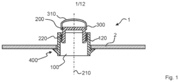
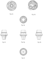
- the Adjustable stopper device 1 for a vehicle door or hood shown in Fig. 1 comprises: a base part 100; an adjustment part 200, wherein the adjustment part 200 is connected to the base part 100 via threads 120, 220 and thereby rotatable around a device axis 210 with respect to the base part 100; a stopper part 300 configured to contact the vehicle door and to provide an abutment surface 310 for the vehicle door when the vehicle door is closed, wherein the stopper part 300 is connected to the adjustment part 200 and wherein the axial position of the abutment surface 310 is adjustable by turning the adjustment part 200 with respect to the base part 100 around the device axis 210; a fastening structure 400 for fastening the base part 100 to the car body 2.
- the device 1 shown in the following figures are based on the device shown in Fig. 1 and comprise a sealing element 500 for sealing against the car body 2 which is surrounding the fastening structure 400.
- the sealing element 500 is made of plastic and formed adhesively onto the base part 100 by an injection molding step.
- the base part 100 is made of a different plastic and in a different injection molding step than the sealing element 500, wherein the plastic of the sealing element 500 is softer than the plastic of the base part 100.
- the stopper part comprises a central opening 320 into which a tool can be inserted for engagement with the adjustment part 200, in order to rotate the adjustment part 200.
- the thread 120 of the base part 100 is an inner thread and the thread 220 of the adjustment part 200 is an outer thread.
- the adjustment part 200 is formed as a pin, which can be screwed into the base part 100.
- the stopper part 300 is formed as a cap or dome, and built of softer material than the adjustment part 200 and base part 100.
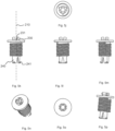
- the device shown in Fig. 2a-2k is an embodiment of the claimed invention and has a fastening structure with three expansion and/or hook elements 411, 412, 150.
- the element 150 is only a hook element, whereas the elements 411 and 412 are expansion and hook elements.
- a subset of the three expansion and/or hook elements, i.e. the expansion and hook elements 411 and 412, is configured to be brought into a fastening position with respect to a corresponding opening or corresponding openings of the car body 2. When the subset is introduced into the opening or openings and is in the fastening position, the base part 100 is fastened to the car body 2.
- the subset is configured to be brought back, when the base part 100 is fastened to the car body 2, into a release position with respect to the opening or openings of the car body 2, wherein with the subset or the entirety being in the release position, the base part 100 can be removed from the car body 2, in this case pulled out.
- the expansion and/or hook elements 411, 412 preferably comprise one or more flexible portion, which allows the expansion and/or hook element to move between fastening position and release position.
- the device 1 is of the type which is mounted from a substantially different direction than the direction from which the door impinges on the mounted device 1, such that a central axis 3 of the opening or openings of the car body 2, which is perpendicular to the surrounding car body surface, and the device axis 210 define a substantial angle between themselves, when the device 1 is mounted to the car body 2, here 90°.
- the car body 2 comprises one or more openings, cf. Fig. 2h and 2i , for one or more of the multiple expansion and/or hook elements 411, 412, 150, such that, when the device is fastened to the car body 2 the base part 100 is not rotatable with respect to the car body 2 due to a form fitted fastening.
- a subset of the one or more expansion and/or hook elements i.e. the expansion and hook elements 411, 412, is made of metal wherein the base part 100 is made of plastic.
- Two of the expansion and/or hook elements 411, 412 are integrally formed within one component 410, whereby these two of the expansion and/or hook elements 411, 412 are grouped within that component 410, wherein the component 410 is attached to the base part 100.
- the subset 411, 412 is part of a clip component 430 which is clipped or clippable onto the base part 100.
- the component 410 is a clip component.
- the base part 100 comprises a tooth-like protrusion 180, wherein the clip component 430 is clipped or clippable onto the base part 100 by clipping the clip components 430 over the tooth-like protrusion 180.
- At least a portion of the clip component 430 covers a side wall 181 of the tooth-like protrusion 180, here a side wall on the far side with respect to the stopper part 300, such that in the fastened state of the device 1, said portion of the clip component 430 is located in between the side wall 181 of the tooth-like protrusion 180 and the rim of the opening of the car body 2 such that the clip component 430 protects the tooth-like protrusion 180 from being damaged by the rim of the opening of the car body 2.
- the subset of the one or more expansion and/or hook elements i.e. 411, 412
- the subset of the one or more expansion and/or hook elements is configured to be brought into the fastening position by at first introducing a side of the device 1 opposite to the subset into the corresponding opening until a portion of that side abuts on or next to the rim of the opening and then pivoting the device 1 and the base part 100 around that abutted portion, such that by the pivoting, the subset reaches the fastening position in which the expansion and/or hook elements 411, 412 engage behind a rim of the opening or openings.
- the device 1, here the base part 100 comprises as one of the expansion and/or hook elements 411, 412, 150 a rigid hook element 150 at one side which is configured to engage behind the corresponding opening in the car body 2, and the other expansion and hook elements 411, 412 are located at an opposing side.
- the hook element 150 is integrally formed on the base part 100 out of the same material as the base part 100.
- the one side is a side neigh-boring the stopper part 300, and the opposing side is a far side with respect to the stopper part 300.
- the hook element 150 is configured to engage behind the corresponding opening in the car body 2 before or when the expansion and hook elements 411, 412 reach the fastening position in which they engage behind a rim of the opening or openings.
- the subset 411, 412 comprise a distal portion 411.1 having a first inclination with respect to the insertion direction, a proximal portion 411.2 having second inclination opposite to the first inclination and in between an edge 411.3, such that by pulling on the device 1 when its fastened to the car body 2 in a direction opposite to the insertion direction, the subset or the entirety are brought into the release position and further pulling allows to remove the device 1 from the car body 2.
- the first inclination is lower than the second inclination such that a pull-out force is higher than an insertion force of the device 1.
- the proximal end point 411.4 of the proximal portion 411.2 having the second inclination is radially fixed with respect to the device 1.
- the proximal end point 411.4 of the proximal portion 411.2 may be, in the state of the device 1 being mounted, within or before - seen from the insertion side - the opening of the car body 2. 27.
- the device 1 comprises a rotation snap mechanism, which snaps into distinct rotational angle positions, which comprises a first cylindrical portion 170 in the base part 100, coaxially positioned with the base part's 100 thread 120, wherein the inner wall of the first cylindrical portion 170 comprises radially inwards protruding teeth or rips or knobs 171.
- the snap mechanism further comprises a second cylindrical portion 240 of the adjustment part 200, positioned coaxially with the adjustment part's 200 thread 220, wherein the outer wall of the second cylindrical portion 240 comprises radially outwards protruding, resilient teeth or rips or knobs 241, which are configured to engage with the axially extending teeth or rips or knobs 171 and thereby provide a predefined, resistance to a rotation moment which can be overcome by a predefined threshold moment resulting in a repeated deflection and relaxation of the teeth or rips or knobs 241 of the adjustment part 200 radially inwards and outwards while the adjustment part 200 is being turned around the device axis 210.
- the resilient teeth or rips or knobs 241 are resilient by axial cut outs 242 of the cylindrical portion.
- the teeth or rips or knobs 241 are rounded or slanted with respect to tangential direction, hence such that a rotation movement is facilitated, while still generating a moment against rotation due to the deflection of some or all of the teeth or rips or knobs 241.
- the circumscribed circle of the teeth or rips or knobs 241 of the second cylindrical portion 240 is smaller than the circumscribed circle of the thread 220 of the adjustment part (can be especially be seen in Fig. 4e ).
- the incircle described by the teeth or rips or knobs 171 of the first cylindrical portion 170 is smaller than the incircle described by the thread 120 of the base part.
- the threaded portions of base part 100 and adjustment part 200 are distinct and neighboring portions (i.e., axially non overlapping) with respect to the cylindrical portions 170, 240.
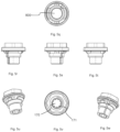
- the device 1 shown in Fig. 3a -g has especially following differences with respect to the one shown in Fig. 2a-2l, otherwise has similar or the same features as the one in Fig. 2a-2l.
- the device 1 has a similar rotation snap mechanism, while alternatively and preferably, the device 1 could have the same rotation snap mechanism as the device 1 of Fig. 2a-k with resilient teeth or ribs or knobs protruding outward on the inner part (i.e. the second cylindrical portion 240).
- the fastening structure 400 comprises four expansion and/or hook elements 411, 412, 421, 422.
- the entirety of the four expansion and/or hook elements is configured to be brought into a fastening position with respect to a corresponding opening or corresponding openings of the car body 2, wherein, when the entirety is introduced into the opening or openings and is in the fastening position, the base part 100 is fastened to the car body 2.
- the entirety is configured to be brought back, when the base part 100 is fastened to the car body 2, into a release position with respect to the opening or openings of the car body 2, wherein with the entirety being in the release position, the base part 100 can be removed from the car body 2, here pulled out.
- the expansion and/or hook elements 411, 412, 421, 422 are integrally formed within two components 410, 420, whereby two of the expansion and/or hook elements 411, 412, 421, 422 are grouped within one component 410, 420, wherein the two components 410, 420 are partly seated and fixed within the base part 100.
- the two components 410, 420 are surrounding the device axis 210 and the threads 120, 220. 20.
- the expansion and/or hook elements 411, 412, 421, 422 are positioned next to a hollow expansion area 423.
- the device 1 comprises one or more bolt elements 600 insertable into the respective expansion area 423 through a bolt opening or bolt openings in the base part 100.
- the one or more expansion and/or hook elements 411, 412, 421, 422 are configured to rest in the release position when the bolt element 600 is not inserted into the respective expansion area 423 and are configured to be maintained in the fastening position when the bolt element 600 is inserted in the respective expansion area 423.
- the bolt element 600 comprises a bolt sealing element 610 configured to seal around the bolt element 600 and the bolt opening or openings in the base part 100.
- the bolt sealing element 610 is formed onto the bolt 600 by a 2-component injection molding process.
- the device 1 shown in Fig. 4a -e shows a design of the type, which is mounted from a substantially same direction as the direction from which the door impinges on the mounted device 1.
- the fastening structure 400 on the back part comprises radial protrusions which engage behind the opening of the car body after the base part 100 is inserted into the whole and rotated around the device axis by a predetermined angel.
- the device 1 has the same rotation sap mechanism as the one of the device 1 shown in Fig. 2a-k .
- the distal end of the first cylindrical portion 170 which is the end at the far side with respect to the position of the adjustment part 200 and stopper part 300, is closed off by the base part's 100 material.
- the material forms a sealing closure 172 of the distal end of a first cylindrical portion 170 in the base part 100 which is molded in the same step, in which the base part 100 is molded, and out of the same material.
- the stopper part 300 is connected by a snap fit to the adjustment part 200.
- the device shown in Fig. 5a -ai in addition comprises a coupling part (700), which is coupling the stopper part (300) to the adjustment part (200), wherein, unlike the device shown in Fig. 4a-e , the stopper part 300 is connected by a snap fit to the coupling part 700, and the coupling part 700 is connected to the adjustment part 200.
- the connection between the adjustment part 200 and the coupling part 700 is formed as a rotational joint, rotating around the device axis 210.
- the connection between the adjustment part 200 and the coupling part 700, which is formed as the rotational joint, is a snap fit connection between the coupling part 700 and the adjustment part 200, comprising
- 1 adjustable stopper device 310 abutment surface 2 car body 320 opening 3 central axis of the opening or openings of the car body 400 fastening structure 410 first component 100 base part 411, 412 expansion and/or hook element 120 thread 150 hook element 411.1 distal portion 160 bolt opening 411.2 proximal portion411.3edge 170 first cylindrical portion 411.4 proximal end point 171 tooth or rip or knob 413 hollow expansion area 172 sealing closure 420 second component 180 tooth-like protrusion 421, 422 expansion and/or hook element 181 side wall 200 adjustment part 423 hollow expansion area 210 device axis 430 Clip component 220 thread 500 sealing element 230 pin 600 bolt element 231 axial cut out 700 coupling part 240 second cylindrical portion 730 circular opening 241 tooth or rip or knob 731 axial cut out 242 axial cut out 800 sealing cove 300 stopper part
Landscapes
- Engineering & Computer Science (AREA)
- Manufacturing & Machinery (AREA)
- Mechanical Engineering (AREA)
- Connection Of Plates (AREA)
- Superstructure Of Vehicle (AREA)
Claims (14)
- Einstellbare Anschlagvorrichtung (1) für eine Fahrzeugtür oder -haube, Folgendes aufweisend- ein Basisteil (100),- ein Einstellteil (200), wobei das Einstellteil (200) mit dem Basisteil (100) über Gewinde (120, 220) verbunden und dadurch um eine Vorrichtungsachse (210) in Bezug auf das Basisteil (100) drehbar ist,- ein Anschlagteil (300), das so ausgebildet ist, dass es die Fahrzeugtür berührt und der Fahrzeugtür eine Anlagefläche (310) bereitstellt, wenn die Fahrzeugtür geschlossen ist, wobei das Anschlagteil (300) mit dem Einstellteil (200) verbunden ist und wobei die axiale Position der Anlagefläche (310) durch Drehen des Einstellteils (200) in Bezug auf das Basisteil (100) um die Vorrichtungsachse (210) einstellbar ist, wobei das Anschlagteil (300) eine zentrale Öffnung (320) aufweist, in die ein Werkzeug zum Eingriff mit dem Einstellteil eingeführt werden kann, um das Einstellteil zu drehen,- eine Befestigungsstruktur (400) zum Befestigen des Basisteils (100) an der Karosserie (2), wobei die Befestigungsstruktur (400) ein oder mehrere Spreiz- und/oder Hakenelemente (411, 412, 421, 422, 150) aufweist,- wobei eine Teilmenge oder die Gesamtheit des einen oder der mehreren Spreiz- und/oder Hakenelemente (411, 412, 421, 422) so ausgebildet ist, dass sie bezüglich einer entsprechenden Öffnung oder entsprechenden Öffnungen der Karosserie (2) in eine Befestigungsstellung gebracht wird, wobei das Basisteil (100) an der Karosserie (2) befestigt ist, wenn die Teilmenge oder die Gesamtheit in die Öffnung bzw. Öffnungen eingeführt ist und sich in der Befestigungsstellung befindet,- wobei die Teilmenge oder die Gesamtheit so ausgebildet ist, dass sie bei an der Karosserie (2) befestigtem Basisteil (100) in eine Lösestellung bezüglich der Öffnung oder Öffnungen der Karosserie (2) zurückgebracht wird, wobei bei in der Lösestellung befindlicher Teilmenge oder Gesamtheit das Basisteil (100) aus der Karosserie (2) entnommen werden kann, undwobei die Teilmenge oder die Gesamtheit des einen oder der mehreren Spreiz- und/oder Hakenelemente (411, 412, 421, 422) Teil einer oder mehrerer Clipkomponenten (430) ist, die auf das Basisteil (100) aufgeclipst sind oder aufgeclipst werden können,- wobei die Teilmenge oder die Gesamtheit des einen oder der mehreren Spreiz- und/oder Hakenelemente (411, 412, 421, 422) einen distalen Abschnitt (411.1) mit einer ersten Neigung bezüglich der Einführrichtung, einen proximalen Abschnitt (411.2) mit einer zweiten Neigung entgegengesetzt zur ersten Neigung und dazwischen eine Kante (411.3) aufweist, derart, dass durch Ziehen an der Vorrichtung (1), wenn sie an der Karosserie (2) entgegen der Einsetzrichtung befestigt ist, die Teilmenge oder die Gesamtheit in die Freigabestellung gebracht wird und ein weiteres Ziehen ermöglicht, die Vorrichtung (1) von der Karosserie (2) zu entfernen; und- wobei der proximale Endpunkt (411.4) des proximalen Abschnitts (411.2) mit der zweiten Neigung in Bezug auf die Vorrichtung (1) radial feststehend ist.
- Vorrichtung nach Anspruch 1, wobei die Vorrichtung (1) ein Dichtelement (500) zur Abdichtung gegenüber der die Befestigungsstruktur (400) umgebenden Karosserie (2) aufweist, wobei das Dichtelement (500) aus Kunststoff besteht und durch einen Spritzgussschritt adhäsiv auf dem Basisteil (100) gebildet ist.
- Vorrichtung (1) nach Anspruch 1, wobei
die Befestigungsstruktur (400) mehrere Spreiz- und/oder Hakenelemente (411, 412, 421, 422, 150) aufweist und die Karosserie (2) eine oder mehrere Öffnungen für ein oder mehrere Spreiz- und/oder Hakenelemente (411, 412, 421, 422, 150) aufweist, derart, dass das Basisteil (100) bei an der Karosserie (2) befestigter Vorrichtung aufgrund einer formschlüssigen Befestigung nicht bezüglich der Karosserie (2) gedreht werden kann. - Vorrichtung (1) nach einem der vorhergehenden Ansprüche, wobei die Teilgruppe oder die Gesamtheit des einen oder der mehreren Spreiz- und/oder Hakenelemente (411, 412, 421, 422) aus Metall besteht, wobei das Basisteil (100) vorzugsweise im Wesentlichen oder vollständig aus Kunststoff besteht.
- Vorrichtung (1) nach einem der vorhergehenden Ansprüche, wobei eine Vielzahl, z. B. zwei oder vier der Spreiz- und/oder Hakenelemente (411, 412, 421, 422) einstückig in einer oder mehreren Komponenten (410, 420) ausgebildet ist, wobei zumindest zwei der Spreiz- und/oder Hakenelemente (411, 412, 421, 422) in einer Komponente (410, 420) gruppiert sind, wobei die eine oder die mehreren Komponenten (410, 420) teilweise im Basisteil (100) sitzt bzw. sitzen und befestigt ist bzw. befestigt sind oder daran angebracht ist bzw. sind, wobei die eine oder die mehreren Komponenten (410, 420) die Vorrichtungsachse (210) optional umgibt bzw. umgeben, vorzugsweise die Gewinde (120, 220).
- Vorrichtung (1) nach einem der vorhergehenden Ansprüche, wobei das Basisteil (100) einen oder mehrere zahnartige Vorsprünge (180) aufweist, wobei das eine oder die mehreren Clipkomponenten (430) auf das Basisteil (100) aufgeclipst werden oder aufclipsbar sind, indem ein oder mehrere des einen oder der mehreren Clipkomponenten (430) über einen oder mehrere der einen oder mehreren zahnartigen Vorsprünge (180) aufgeclipst wird bzw. werden, und wobei zumindest ein Abschnitt des einen oder der mehreren Clipbauteile (430) optional eine Seitenwand (181) des einen oder der mehreren zahnartigen Vorsprünge (180) derart bedeckt, dass der Abschnitt des einen oder der mehreren Clipkomponenten (430) zwischen der Seitenwand (181) des einen oder der mehreren zahnartigen Vorsprünge (180) und dem Rand der Öffnung der Karosserie (2) im befestigten Zustand der Vorrichtung (1) derart angeordnet ist, dass das eine oder die mehreren Clipkomponenten (430) die zahnartigen Vorsprünge (180) vor einer Beschädigung durch den Rand der Öffnung der Karosserie (2) schützen.
- Vorrichtung (1) nach einem der vorhergehenden Ansprüche, wobei die Teilmenge oder die Gesamtheit des einen oder der mehreren Spreiz- und/oder Hakenelemente (411, 412, 421, 422) so ausgebildet ist, dass sie in die Befestigungsstellung gebracht werden, indem zunächst eine Seite der Vorrichtung (1), die der Teilmenge gegenüberliegt, oder die Gesamtheit des einen oder der mehreren Spreiz- und/oder Hakenelemente (411, 412, 421, 422) in die entsprechende Öffnung oder Öffnungen eingeführt wird, bis ein Abschnitt dieser Seite an oder neben dem Rand der Öffnung anliegt und dann die Vorrichtung (1) und/oder das Basisteil (100) um diesen anliegenden Abschnitt gedreht wird, sodass durch das Drehen die Teilmenge oder die Gesamtheit des einen oder der mehreren Spreiz- und/oder Hakenelemente (411, 412, 421, 422) die Befestigungsstellung erreicht, in der sie einen Rand der Öffnung bzw. der Öffnungen hintergreift.
- Vorrichtung (1) nach einem der vorhergehenden Ansprüche, wobei die Vorrichtung (1) als eines der Spreiz- und/oder Hakenelemente (411, 412, 421, 422, 150) mindestens ein Hakenelement (150) an einer Seite aufweist, das so ausgebildet ist, dass es die entsprechende Öffnung in der Karosserie (2) hintergreift, und andere des einen oder der mehreren Spreiz- und/oder Hakenelemente (411, 412, 421, 422) an einer gegenüberliegenden Seite angeordnet sind, und wobei die eine Seite optional eine Seite ist, die an das Anschlagteil (300) angrenzt, und die gegenüberliegende Seite in Bezug auf das Anschlagteil (300) eine entfernte Seite ist.
- Vorrichtung (1) nach Anspruch 7 und Anspruch 8, wobei das Hakenelement (150) so ausgebildet ist, dass es die entsprechende Öffnung in der Karosserie (2) hintergreift, bevor oder wenn das eine oder die mehreren Spreiz- und/oder Hakenelemente (411, 412, 421, 422) die Befestigungsstellung erreichen, in der sie hinter einen Rand der Öffnung oder Öffnungen eingreifen.
- Vorrichtung (1) nach Anspruch 1, wobei die erste Neigung geringer ist als die zweite Neigung, sodass eine Auszugskraft höher ist als eine Einführkraft der Vorrichtung (1) und/oder wobei der proximale Endpunkt (411.4) des proximalen Abschnitts (411.2) im Zustand ist, in dem die Vorrichtung (1) montiert ist, - von der Einführseite gesehen - in oder vor der Öffnung der Karosserie (2).
- Vorrichtung nach einem der vorhergehenden Ansprüche, wobei die Vorrichtung einen Drehschnappmechanismus aufweist, der in verschiedene Drehwinkelpositionen einschnappt, der Folgendes aufweist- einen ersten zylindrischen Abschnitt (170) im Basisteil (100), der koaxial zum Gewinde (120) des Basisteils (100) angeordnet ist, wobei die Innenwand des ersten zylindrischen Abschnitts (170) einen oder mehrere radial nach innen vorstehende Zähne oder Rippen oder Noppen (171) aufweist, und- einen zweiten zylindrischen Abschnitt (240) des Einstellteils (200), der koaxial zum Gewinde (220) des Einstellteils (200) angeordnet ist, wobei die Außenwand des zweiten zylindrischen Abschnitts (240) einen oder mehrere radial nach außen vorstehende elastische Zähne oder Rippen oder Noppen (241) aufweist, der bzw. die so ausgebildet ist bzw. sind, dass er bzw. sie mit den sich axial erstreckenden Zähnen oder Rippen oder Noppen (171) in Eingriff kommt bzw. kommen und dadurch einen vordefinierten Widerstand gegen ein Drehmoment bereitstellen, das durch ein vordefiniertes Schwellenmoment überwunden werden kann, wodurch es zu einer wiederholten Biegung und Entspannung des bzw. der einen oder der mehreren Zähne oder Rippen oder Noppen (241) des Einstellteils (200) radial nach innen und nach außen kommt, während das Einstellteil (200) um die Vorrichtungsachse (210) gedreht wird; und wobei optional:
das distale Ende des ersten zylindrischen Abschnitts (170), d. h. das Ende an der entfernten Seite bezüglich der Position des Einstellteils (200) und/oder des Anschlagteils (300) durch das Material des Basisteils (100) verschlossen ist, oder- durch einen mittels eines Zweikomponenten-Spritzgussverfahrens, vorzugsweise im gleichen Spritzgussschritt wie das Dichtelement (500), auf dem Basisteil (100) geformten Dichtungsdeckel (800), abgedeckt ist. - Fahrzeug, das eine Tür oder Haube und eine Karosserie (2) und eine Vorrichtung (1) nach einem der vorhergehenden Ansprüche aufweist.
- Verwendung einer Vorrichtung (1) nach einem der Ansprüche 1 bis 11 für eine Fahrzeugtür oder -haube.
- Verfahren zur Herstellung einer einstellbaren Anschlagvorrichtung (1) für eine Fahrzeugtür oder -haube nach einem der Ansprüche 1 bis 11, Folgendes aufweisend- Bilden eines Basisteils (100) durch Spritzgießen, wodurch ein Gewinde (120) des Basisteils (100) gebildet wird,- Bilden eines Einstellteils (200) durch Spritzgießen, wobei ein Gewinde (220) des Einstellteils (200) gebildet wird,- Bilden eines Anschlagteils (300) durch Spritzgießen,- Aufbauen einer Befestigungsstruktur (400) zum Befestigen des Basisteils (100) an der Fahrzeugkarosserie.
Priority Applications (1)
| Application Number | Priority Date | Filing Date | Title |
|---|---|---|---|
| EP19215722.0A EP3653823B1 (de) | 2016-09-29 | 2017-09-19 | Verstellbares stopperelement mit verbesserter fixierung und/oder verstellbarkeit |
Applications Claiming Priority (3)
| Application Number | Priority Date | Filing Date | Title |
|---|---|---|---|
| EP16191379 | 2016-09-29 | ||
| EP17173617 | 2017-05-31 | ||
| PCT/US2017/052131 WO2018063847A1 (en) | 2016-09-29 | 2017-09-19 | Adjustable stopper element with improved fixation and/or adjustability |
Related Child Applications (2)
| Application Number | Title | Priority Date | Filing Date |
|---|---|---|---|
| EP19215722.0A Division EP3653823B1 (de) | 2016-09-29 | 2017-09-19 | Verstellbares stopperelement mit verbesserter fixierung und/oder verstellbarkeit |
| EP19215722.0A Division-Into EP3653823B1 (de) | 2016-09-29 | 2017-09-19 | Verstellbares stopperelement mit verbesserter fixierung und/oder verstellbarkeit |
Publications (2)
| Publication Number | Publication Date |
|---|---|
| EP3519657A1 EP3519657A1 (de) | 2019-08-07 |
| EP3519657B1 true EP3519657B1 (de) | 2025-06-04 |
Family
ID=59955765
Family Applications (2)
| Application Number | Title | Priority Date | Filing Date |
|---|---|---|---|
| EP17772293.1A Active EP3519657B1 (de) | 2016-09-29 | 2017-09-19 | Verstellbares stopperelement mit verbesserter fixierung und/oder einstellbarkeit |
| EP19215722.0A Active EP3653823B1 (de) | 2016-09-29 | 2017-09-19 | Verstellbares stopperelement mit verbesserter fixierung und/oder verstellbarkeit |
Family Applications After (1)
| Application Number | Title | Priority Date | Filing Date |
|---|---|---|---|
| EP19215722.0A Active EP3653823B1 (de) | 2016-09-29 | 2017-09-19 | Verstellbares stopperelement mit verbesserter fixierung und/oder verstellbarkeit |
Country Status (4)
| Country | Link |
|---|---|
| US (1) | US10689894B2 (de) |
| EP (2) | EP3519657B1 (de) |
| CN (2) | CN111502462B (de) |
| WO (1) | WO2018063847A1 (de) |
Families Citing this family (8)
| Publication number | Priority date | Publication date | Assignee | Title |
|---|---|---|---|---|
| FR3079594B1 (fr) * | 2018-03-30 | 2020-03-06 | A. Raymond Et Cie | Dispositif d'ajustement de l'elevation d'une piece |
| US11143451B2 (en) * | 2018-10-12 | 2021-10-12 | Bsh Hausgeraete Gmbh | Household appliance having a part being releasably attached |
| KR102070640B1 (ko) * | 2019-06-07 | 2020-01-29 | 주식회사 디엠씨 | 고정력과 완충성을 구비한 오버슬램범퍼 |
| DE102021118920A1 (de) | 2020-08-13 | 2022-02-17 | Illinois Tool Works Inc. | Toleranzausgleichsvorrichtung |
| JP7504285B2 (ja) * | 2021-03-12 | 2024-06-21 | 株式会社パイオラックス | ストッパー装置 |
| KR102909376B1 (ko) * | 2021-04-15 | 2026-01-07 | 현대자동차 주식회사 | 차량용 오버 슬램 범퍼 장치 |
| DE102022108487A1 (de) | 2021-04-23 | 2022-10-27 | Illinois Tool Works Inc. | Abstandhaltervorrichtung |
| US12473756B2 (en) * | 2021-10-27 | 2025-11-18 | The Boeing Company | Adjustable latch systems and methods |
Citations (5)
| Publication number | Priority date | Publication date | Assignee | Title |
|---|---|---|---|---|
| JP2003307244A (ja) * | 2002-04-15 | 2003-10-31 | Toyota Auto Body Co Ltd | クッションゴム |
| JP2006008096A (ja) * | 2004-05-25 | 2006-01-12 | Daiwa Kasei Ind Co Ltd | クッションクリップ |
| DE102011101393A1 (de) * | 2011-05-13 | 2012-11-15 | Audi Ag | Anschlagpufferanordnung mit einem Dreh-Verstellmechanismus und mit einem Dreh-Rastmechanismus |
| FR3002574A1 (fr) * | 2013-02-27 | 2014-08-29 | Mgi Coutier Espana Sl | Butee a hauteur auto-reglable pour un ouvrant de vehicule automobile et procede pour regler une telle butee |
| WO2015094457A1 (en) * | 2013-12-16 | 2015-06-25 | Illinois Tool Works Inc. | Self-adjusting spacer device |
Family Cites Families (24)
| Publication number | Priority date | Publication date | Assignee | Title |
|---|---|---|---|---|
| DE19514944C1 (de) * | 1995-04-22 | 1996-10-24 | Itw Ateco Gmbh | Selbstjustierender Dämfungsanschlag für bewegliche Teile |
| DE29716111U1 (de) * | 1997-09-08 | 1997-11-13 | United Carr Gmbh Trw | Anschlagelement |
| US6119306A (en) | 1998-05-22 | 2000-09-19 | Southco, Inc. | Automotive deck lid bumper |
| US6088878A (en) * | 1998-05-22 | 2000-07-18 | Southco, Inc. | Height adjustable automotive deck lid bumper |
| DE20010282U1 (de) * | 2000-06-08 | 2000-08-31 | Arturo Salice S.P.A., Novedrate, Como | Vorrichtung zum Dämpfen von Stößen, vorzugsweise der Stöße von Möbeltüren oder Schubladen |
| JP4329888B2 (ja) * | 2000-07-06 | 2009-09-09 | 株式会社ニフコ | 緩衝装置 |
| DE10035201A1 (de) * | 2000-07-20 | 2002-02-07 | Opel Adam Ag | Einstellbares Dämpfungselement und Verfahren zu dessen Einstellung |
| IT1321053B1 (it) * | 2000-11-09 | 2003-12-30 | Fiat Auto Spa | Tampone di battuta regolabile per una parte mobile della carrozzeriadi un autoveicolo. |
| JP4085013B2 (ja) * | 2003-02-21 | 2008-04-30 | 日産自動車株式会社 | 緩衝装置 |
| EP1473469A1 (de) * | 2003-04-29 | 2004-11-03 | Itw Espana, Sa | Niete zur Befestigung von Teilen an einer Fahrzeugkarosserie |
| DE202004012733U1 (de) * | 2004-08-13 | 2004-10-21 | Böllhoff Verbindungstechnik GmbH | Einstelleinheit zum Einstellen des Abstandes zwischen zwei Bauteilen |
| AT10097U1 (de) * | 2007-04-30 | 2008-09-15 | Blum Gmbh Julius | Federpuffer für ein möbel |
| CN201068920Y (zh) * | 2007-07-27 | 2008-06-04 | 重庆长安汽车股份有限公司 | 汽车用防旋转撑条固定座 |
| JP4756219B2 (ja) * | 2007-09-21 | 2011-08-24 | ポップリベット・ファスナー株式会社 | カーテンサイドエアバッグ用トリムのためのトリムクリップ |
| DE102010015064B4 (de) * | 2010-04-15 | 2012-09-06 | D. la Porte Söhne GmbH | Feststeller für eine Fahrzeugtür oder -klappe |
| EP2614995B1 (de) * | 2010-09-07 | 2014-11-26 | Toyota Jidosha Kabushiki Kaisha | Ziermontagevorrichtung |
| US8616622B2 (en) * | 2011-07-28 | 2013-12-31 | Maclean Fogg Company | Energy management hood bumper |
| GB2519252B (en) * | 2012-08-07 | 2019-03-20 | Piolax Inc | Damper |
| JP5822096B2 (ja) * | 2012-09-28 | 2015-11-24 | 豊田合成株式会社 | 部品の取付構造 |
| FR3011869B1 (fr) * | 2013-10-14 | 2018-06-22 | A Raymond Et Cie | Dispositif de tampon a butee auto ajustable |
| US9963917B2 (en) * | 2013-12-13 | 2018-05-08 | Ford Global Technologies, Llc | Hood stop assemblies for a vehicle and methods for setting a position of a vehicle hood |
| CN103754167A (zh) * | 2014-01-17 | 2014-04-30 | 深圳市豪恩汽车电子装备有限公司 | 倒车雷达控制器 |
| DE102015100978B4 (de) * | 2015-01-23 | 2024-06-13 | Dr. Ing. H.C. F. Porsche Aktiengesellschaft | Aufstellvorrichtung für eine Heckklappe eines Kraftfahrzeugs |
| US10150444B1 (en) * | 2017-09-15 | 2018-12-11 | Ford Global Technologies, Llc | Frangible bump stop support |
-
2017
- 2017-09-19 CN CN201911337092.1A patent/CN111502462B/zh active Active
- 2017-09-19 EP EP17772293.1A patent/EP3519657B1/de active Active
- 2017-09-19 CN CN201780060324.6A patent/CN109790736B/zh active Active
- 2017-09-19 EP EP19215722.0A patent/EP3653823B1/de active Active
- 2017-09-19 US US16/335,942 patent/US10689894B2/en active Active
- 2017-09-19 WO PCT/US2017/052131 patent/WO2018063847A1/en not_active Ceased
Patent Citations (5)
| Publication number | Priority date | Publication date | Assignee | Title |
|---|---|---|---|---|
| JP2003307244A (ja) * | 2002-04-15 | 2003-10-31 | Toyota Auto Body Co Ltd | クッションゴム |
| JP2006008096A (ja) * | 2004-05-25 | 2006-01-12 | Daiwa Kasei Ind Co Ltd | クッションクリップ |
| DE102011101393A1 (de) * | 2011-05-13 | 2012-11-15 | Audi Ag | Anschlagpufferanordnung mit einem Dreh-Verstellmechanismus und mit einem Dreh-Rastmechanismus |
| FR3002574A1 (fr) * | 2013-02-27 | 2014-08-29 | Mgi Coutier Espana Sl | Butee a hauteur auto-reglable pour un ouvrant de vehicule automobile et procede pour regler une telle butee |
| WO2015094457A1 (en) * | 2013-12-16 | 2015-06-25 | Illinois Tool Works Inc. | Self-adjusting spacer device |
Also Published As
| Publication number | Publication date |
|---|---|
| EP3653823A1 (de) | 2020-05-20 |
| WO2018063847A1 (en) | 2018-04-05 |
| EP3519657A1 (de) | 2019-08-07 |
| US20190309555A1 (en) | 2019-10-10 |
| CN111502462A (zh) | 2020-08-07 |
| EP3653823B1 (de) | 2023-12-13 |
| CN109790736A (zh) | 2019-05-21 |
| CN109790736B (zh) | 2022-06-17 |
| US10689894B2 (en) | 2020-06-23 |
| CN111502462B (zh) | 2023-01-10 |
Similar Documents
| Publication | Publication Date | Title |
|---|---|---|
| EP3519657B1 (de) | Verstellbares stopperelement mit verbesserter fixierung und/oder einstellbarkeit | |
| US10961763B2 (en) | Adjustable stopper element with improved fixation and/or adjustability | |
| EP2679515B1 (de) | Lüftungsvorrichtung | |
| JP5841220B1 (ja) | 蓋付き容器 | |
| US8776326B2 (en) | Panel connection snap assembly | |
| US10118001B2 (en) | Rigid needle shield gripping cap assembly | |
| JPH02118213A (ja) | 押込みファスナ | |
| JP5956746B2 (ja) | ロッドを受けるための受け部および骨固定装置 | |
| US8572818B2 (en) | Connecting assembly for fastening an add-on element on a carrier | |
| US20180186305A1 (en) | Service hole fastening clip assembly | |
| KR102058490B1 (ko) | 스틱용 길이 조정 가능 튜브 | |
| US20090188086A1 (en) | Clip | |
| US7862274B2 (en) | Fastener to affix a component to a support with aperture | |
| US6612796B2 (en) | Push-in fastener assembly with interfering element | |
| US20100119325A1 (en) | Stud retaining fastener assembly | |
| KR20190087328A (ko) | 리벳 파스너 조립체 및 그 사용 방법 | |
| JP2009079751A (ja) | 雌ねじ用穴塞ぎプラグ | |
| US20200325926A1 (en) | Fastener | |
| US12385510B2 (en) | Tolerance compensation fastening assembly | |
| US10221873B2 (en) | Pin and grommet fastener assembly | |
| WO2008094804A1 (en) | Pop off nipple snap on fastener for sun shade technology | |
| KR200484392Y1 (ko) | 의료용 카테터 | |
| CN116357654A (zh) | 公差补偿紧固组件 | |
| US12006958B2 (en) | Rivet fastener assembly and method of use thereof | |
| KR20170050424A (ko) | 지지리브를 구비하는 볼 조인트 |
Legal Events
| Date | Code | Title | Description |
|---|---|---|---|
| STAA | Information on the status of an ep patent application or granted ep patent |
Free format text: STATUS: UNKNOWN |
|
| STAA | Information on the status of an ep patent application or granted ep patent |
Free format text: STATUS: THE INTERNATIONAL PUBLICATION HAS BEEN MADE |
|
| PUAI | Public reference made under article 153(3) epc to a published international application that has entered the european phase |
Free format text: ORIGINAL CODE: 0009012 |
|
| STAA | Information on the status of an ep patent application or granted ep patent |
Free format text: STATUS: REQUEST FOR EXAMINATION WAS MADE |
|
| 17P | Request for examination filed |
Effective date: 20190425 |
|
| AK | Designated contracting states |
Kind code of ref document: A1 Designated state(s): AL AT BE BG CH CY CZ DE DK EE ES FI FR GB GR HR HU IE IS IT LI LT LU LV MC MK MT NL NO PL PT RO RS SE SI SK SM TR |
|
| AX | Request for extension of the european patent |
Extension state: BA ME |
|
| DAV | Request for validation of the european patent (deleted) | ||
| DAX | Request for extension of the european patent (deleted) | ||
| PUAG | Search results despatched under rule 164(2) epc together with communication from examining division |
Free format text: ORIGINAL CODE: 0009017 |
|
| STAA | Information on the status of an ep patent application or granted ep patent |
Free format text: STATUS: EXAMINATION IS IN PROGRESS |
|
| 17Q | First examination report despatched |
Effective date: 20221223 |
|
| B565 | Issuance of search results under rule 164(2) epc |
Effective date: 20221223 |
|
| RIC1 | Information provided on ipc code assigned before grant |
Ipc: E05F 5/02 20060101AFI20221220BHEP |
|
| RIN1 | Information on inventor provided before grant (corrected) |
Inventor name: SPANIER, MARCO Inventor name: STELLWAG, PHILIP Inventor name: PARES ISANTA, ALBERT Inventor name: MARTIN MARINO, IVAN Inventor name: DIEZ HERRERA, VICTOR |
|
| GRAP | Despatch of communication of intention to grant a patent |
Free format text: ORIGINAL CODE: EPIDOSNIGR1 |
|
| STAA | Information on the status of an ep patent application or granted ep patent |
Free format text: STATUS: GRANT OF PATENT IS INTENDED |
|
| INTG | Intention to grant announced |
Effective date: 20241111 |
|
| GRAJ | Information related to disapproval of communication of intention to grant by the applicant or resumption of examination proceedings by the epo deleted |
Free format text: ORIGINAL CODE: EPIDOSDIGR1 |
|
| STAA | Information on the status of an ep patent application or granted ep patent |
Free format text: STATUS: EXAMINATION IS IN PROGRESS |
|
| GRAP | Despatch of communication of intention to grant a patent |
Free format text: ORIGINAL CODE: EPIDOSNIGR1 |
|
| STAA | Information on the status of an ep patent application or granted ep patent |
Free format text: STATUS: GRANT OF PATENT IS INTENDED |
|
| INTC | Intention to grant announced (deleted) | ||
| INTG | Intention to grant announced |
Effective date: 20250128 |
|
| P01 | Opt-out of the competence of the unified patent court (upc) registered |
Free format text: CASE NUMBER: APP_9472/2025 Effective date: 20250225 |
|
| GRAS | Grant fee paid |
Free format text: ORIGINAL CODE: EPIDOSNIGR3 |
|
| GRAA | (expected) grant |
Free format text: ORIGINAL CODE: 0009210 |
|
| STAA | Information on the status of an ep patent application or granted ep patent |
Free format text: STATUS: THE PATENT HAS BEEN GRANTED |
|
| AK | Designated contracting states |
Kind code of ref document: B1 Designated state(s): AL AT BE BG CH CY CZ DE DK EE ES FI FR GB GR HR HU IE IS IT LI LT LU LV MC MK MT NL NO PL PT RO RS SE SI SK SM TR |
|
| REG | Reference to a national code |
Ref country code: GB Ref legal event code: FG4D |
|
| REG | Reference to a national code |
Ref country code: CH Ref legal event code: EP |
|
| REG | Reference to a national code |
Ref country code: DE Ref legal event code: R096 Ref document number: 602017089772 Country of ref document: DE |
|
| REG | Reference to a national code |
Ref country code: IE Ref legal event code: FG4D |
|
| REG | Reference to a national code |
Ref country code: NL Ref legal event code: MP Effective date: 20250604 |
|
| PG25 | Lapsed in a contracting state [announced via postgrant information from national office to epo] |
Ref country code: FI Free format text: LAPSE BECAUSE OF FAILURE TO SUBMIT A TRANSLATION OF THE DESCRIPTION OR TO PAY THE FEE WITHIN THE PRESCRIBED TIME-LIMIT Effective date: 20250604 Ref country code: ES Free format text: LAPSE BECAUSE OF FAILURE TO SUBMIT A TRANSLATION OF THE DESCRIPTION OR TO PAY THE FEE WITHIN THE PRESCRIBED TIME-LIMIT Effective date: 20250604 |
|
| PGFP | Annual fee paid to national office [announced via postgrant information from national office to epo] |
Ref country code: DE Payment date: 20250929 Year of fee payment: 9 |
|
| REG | Reference to a national code |
Ref country code: LT Ref legal event code: MG9D |
|
| PG25 | Lapsed in a contracting state [announced via postgrant information from national office to epo] |
Ref country code: GR Free format text: LAPSE BECAUSE OF FAILURE TO SUBMIT A TRANSLATION OF THE DESCRIPTION OR TO PAY THE FEE WITHIN THE PRESCRIBED TIME-LIMIT Effective date: 20250905 Ref country code: NO Free format text: LAPSE BECAUSE OF FAILURE TO SUBMIT A TRANSLATION OF THE DESCRIPTION OR TO PAY THE FEE WITHIN THE PRESCRIBED TIME-LIMIT Effective date: 20250904 |
|
| PG25 | Lapsed in a contracting state [announced via postgrant information from national office to epo] |
Ref country code: PL Free format text: LAPSE BECAUSE OF FAILURE TO SUBMIT A TRANSLATION OF THE DESCRIPTION OR TO PAY THE FEE WITHIN THE PRESCRIBED TIME-LIMIT Effective date: 20250604 |
|
| PG25 | Lapsed in a contracting state [announced via postgrant information from national office to epo] |
Ref country code: BG Free format text: LAPSE BECAUSE OF FAILURE TO SUBMIT A TRANSLATION OF THE DESCRIPTION OR TO PAY THE FEE WITHIN THE PRESCRIBED TIME-LIMIT Effective date: 20250604 |
|
| PG25 | Lapsed in a contracting state [announced via postgrant information from national office to epo] |
Ref country code: HR Free format text: LAPSE BECAUSE OF FAILURE TO SUBMIT A TRANSLATION OF THE DESCRIPTION OR TO PAY THE FEE WITHIN THE PRESCRIBED TIME-LIMIT Effective date: 20250604 |
|
| PG25 | Lapsed in a contracting state [announced via postgrant information from national office to epo] |
Ref country code: RS Free format text: LAPSE BECAUSE OF FAILURE TO SUBMIT A TRANSLATION OF THE DESCRIPTION OR TO PAY THE FEE WITHIN THE PRESCRIBED TIME-LIMIT Effective date: 20250904 |
|
| PG25 | Lapsed in a contracting state [announced via postgrant information from national office to epo] |
Ref country code: LV Free format text: LAPSE BECAUSE OF FAILURE TO SUBMIT A TRANSLATION OF THE DESCRIPTION OR TO PAY THE FEE WITHIN THE PRESCRIBED TIME-LIMIT Effective date: 20250604 |
|
| PG25 | Lapsed in a contracting state [announced via postgrant information from national office to epo] |
Ref country code: NL Free format text: LAPSE BECAUSE OF FAILURE TO SUBMIT A TRANSLATION OF THE DESCRIPTION OR TO PAY THE FEE WITHIN THE PRESCRIBED TIME-LIMIT Effective date: 20250604 |
|
| PG25 | Lapsed in a contracting state [announced via postgrant information from national office to epo] |
Ref country code: PT Free format text: LAPSE BECAUSE OF FAILURE TO SUBMIT A TRANSLATION OF THE DESCRIPTION OR TO PAY THE FEE WITHIN THE PRESCRIBED TIME-LIMIT Effective date: 20251006 |
|
| REG | Reference to a national code |
Ref country code: AT Ref legal event code: MK05 Ref document number: 1800481 Country of ref document: AT Kind code of ref document: T Effective date: 20250604 |
|
| PG25 | Lapsed in a contracting state [announced via postgrant information from national office to epo] |
Ref country code: IS Free format text: LAPSE BECAUSE OF FAILURE TO SUBMIT A TRANSLATION OF THE DESCRIPTION OR TO PAY THE FEE WITHIN THE PRESCRIBED TIME-LIMIT Effective date: 20251004 |
|
| PG25 | Lapsed in a contracting state [announced via postgrant information from national office to epo] |
Ref country code: AT Free format text: LAPSE BECAUSE OF FAILURE TO SUBMIT A TRANSLATION OF THE DESCRIPTION OR TO PAY THE FEE WITHIN THE PRESCRIBED TIME-LIMIT Effective date: 20250604 Ref country code: SM Free format text: LAPSE BECAUSE OF FAILURE TO SUBMIT A TRANSLATION OF THE DESCRIPTION OR TO PAY THE FEE WITHIN THE PRESCRIBED TIME-LIMIT Effective date: 20250604 |
|
| PG25 | Lapsed in a contracting state [announced via postgrant information from national office to epo] |
Ref country code: CZ Free format text: LAPSE BECAUSE OF FAILURE TO SUBMIT A TRANSLATION OF THE DESCRIPTION OR TO PAY THE FEE WITHIN THE PRESCRIBED TIME-LIMIT Effective date: 20250604 |
|
| PG25 | Lapsed in a contracting state [announced via postgrant information from national office to epo] |
Ref country code: EE Free format text: LAPSE BECAUSE OF FAILURE TO SUBMIT A TRANSLATION OF THE DESCRIPTION OR TO PAY THE FEE WITHIN THE PRESCRIBED TIME-LIMIT Effective date: 20250604 |
|
| PG25 | Lapsed in a contracting state [announced via postgrant information from national office to epo] |
Ref country code: SK Free format text: LAPSE BECAUSE OF FAILURE TO SUBMIT A TRANSLATION OF THE DESCRIPTION OR TO PAY THE FEE WITHIN THE PRESCRIBED TIME-LIMIT Effective date: 20250604 Ref country code: RO Free format text: LAPSE BECAUSE OF FAILURE TO SUBMIT A TRANSLATION OF THE DESCRIPTION OR TO PAY THE FEE WITHIN THE PRESCRIBED TIME-LIMIT Effective date: 20250604 |
|
| PG25 | Lapsed in a contracting state [announced via postgrant information from national office to epo] |
Ref country code: IT Free format text: LAPSE BECAUSE OF FAILURE TO SUBMIT A TRANSLATION OF THE DESCRIPTION OR TO PAY THE FEE WITHIN THE PRESCRIBED TIME-LIMIT Effective date: 20250604 |