EP3518645B1 - Control method for a component supply system and component supply system for performing the control method - Google Patents
Control method for a component supply system and component supply system for performing the control method Download PDFInfo
- Publication number
- EP3518645B1 EP3518645B1 EP16916782.2A EP16916782A EP3518645B1 EP 3518645 B1 EP3518645 B1 EP 3518645B1 EP 16916782 A EP16916782 A EP 16916782A EP 3518645 B1 EP3518645 B1 EP 3518645B1
- Authority
- EP
- European Patent Office
- Prior art keywords
- component
- leaded
- component supply
- components
- section
- Prior art date
- Legal status (The legal status is an assumption and is not a legal conclusion. Google has not performed a legal analysis and makes no representation as to the accuracy of the status listed.)
- Active
Links
- 238000000034 method Methods 0.000 title claims description 22
- 238000003384 imaging method Methods 0.000 claims description 62
- 210000000078 claw Anatomy 0.000 description 6
- 238000003780 insertion Methods 0.000 description 5
- 230000037431 insertion Effects 0.000 description 5
- 238000012546 transfer Methods 0.000 description 4
- 238000012545 processing Methods 0.000 description 3
- 238000007796 conventional method Methods 0.000 description 2
- 238000007599 discharging Methods 0.000 description 2
- 238000010276 construction Methods 0.000 description 1
- 238000010586 diagram Methods 0.000 description 1
- 230000000694 effects Effects 0.000 description 1
- 238000005516 engineering process Methods 0.000 description 1
- 230000002452 interceptive effect Effects 0.000 description 1
- 238000005259 measurement Methods 0.000 description 1
Images


Classifications
-
- B—PERFORMING OPERATIONS; TRANSPORTING
- B25—HAND TOOLS; PORTABLE POWER-DRIVEN TOOLS; MANIPULATORS
- B25J—MANIPULATORS; CHAMBERS PROVIDED WITH MANIPULATION DEVICES
- B25J9/00—Programme-controlled manipulators
- B25J9/16—Programme controls
- B25J9/1694—Programme controls characterised by use of sensors other than normal servo-feedback from position, speed or acceleration sensors, perception control, multi-sensor controlled systems, sensor fusion
- B25J9/1697—Vision controlled systems
-
- H—ELECTRICITY
- H05—ELECTRIC TECHNIQUES NOT OTHERWISE PROVIDED FOR
- H05K—PRINTED CIRCUITS; CASINGS OR CONSTRUCTIONAL DETAILS OF ELECTRIC APPARATUS; MANUFACTURE OF ASSEMBLAGES OF ELECTRICAL COMPONENTS
- H05K13/00—Apparatus or processes specially adapted for manufacturing or adjusting assemblages of electric components
- H05K13/02—Feeding of components
- H05K13/028—Simultaneously loading a plurality of loose objects, e.g. by means of vibrations, pressure differences, magnetic fields
-
- H—ELECTRICITY
- H05—ELECTRIC TECHNIQUES NOT OTHERWISE PROVIDED FOR
- H05K—PRINTED CIRCUITS; CASINGS OR CONSTRUCTIONAL DETAILS OF ELECTRIC APPARATUS; MANUFACTURE OF ASSEMBLAGES OF ELECTRICAL COMPONENTS
- H05K13/00—Apparatus or processes specially adapted for manufacturing or adjusting assemblages of electric components
- H05K13/04—Mounting of components, e.g. of leadless components
- H05K13/043—Feeding one by one by other means than belts
-
- H—ELECTRICITY
- H05—ELECTRIC TECHNIQUES NOT OTHERWISE PROVIDED FOR
- H05K—PRINTED CIRCUITS; CASINGS OR CONSTRUCTIONAL DETAILS OF ELECTRIC APPARATUS; MANUFACTURE OF ASSEMBLAGES OF ELECTRICAL COMPONENTS
- H05K13/00—Apparatus or processes specially adapted for manufacturing or adjusting assemblages of electric components
- H05K13/08—Monitoring manufacture of assemblages
- H05K13/081—Integration of optical monitoring devices in assembly lines; Processes using optical monitoring devices specially adapted for controlling devices or machines in assembly lines
- H05K13/0812—Integration of optical monitoring devices in assembly lines; Processes using optical monitoring devices specially adapted for controlling devices or machines in assembly lines the monitoring devices being integrated in the mounting machine, e.g. for monitoring components, leads, component placement
-
- H—ELECTRICITY
- H05—ELECTRIC TECHNIQUES NOT OTHERWISE PROVIDED FOR
- H05K—PRINTED CIRCUITS; CASINGS OR CONSTRUCTIONAL DETAILS OF ELECTRIC APPARATUS; MANUFACTURE OF ASSEMBLAGES OF ELECTRICAL COMPONENTS
- H05K13/00—Apparatus or processes specially adapted for manufacturing or adjusting assemblages of electric components
- H05K13/08—Monitoring manufacture of assemblages
- H05K13/081—Integration of optical monitoring devices in assembly lines; Processes using optical monitoring devices specially adapted for controlling devices or machines in assembly lines
- H05K13/0813—Controlling of single components prior to mounting, e.g. orientation, component geometry
-
- G—PHYSICS
- G05—CONTROLLING; REGULATING
- G05B—CONTROL OR REGULATING SYSTEMS IN GENERAL; FUNCTIONAL ELEMENTS OF SUCH SYSTEMS; MONITORING OR TESTING ARRANGEMENTS FOR SUCH SYSTEMS OR ELEMENTS
- G05B2219/00—Program-control systems
- G05B2219/30—Nc systems
- G05B2219/37—Measurements
- G05B2219/37572—Camera, tv, vision
-
- G—PHYSICS
- G05—CONTROLLING; REGULATING
- G05B—CONTROL OR REGULATING SYSTEMS IN GENERAL; FUNCTIONAL ELEMENTS OF SUCH SYSTEMS; MONITORING OR TESTING ARRANGEMENTS FOR SUCH SYSTEMS OR ELEMENTS
- G05B2219/00—Program-control systems
- G05B2219/30—Nc systems
- G05B2219/50—Machine tool, machine tool null till machine tool work handling
Definitions
- an index value that specifies a size of a side surface of a component is calculated based on imaging data of a component captured by an imaging device. Then, in a case in which the calculated index value matches a set value, it is determined that it is possible to hold the component. In other words, in a case in which there is a certain distance between multiple components, from imaging a side surface of the component, if an index value that specifies the size of the side surface of the component matches the set value, it is determined that it is possible to hold the component. Accordingly, it is possible to determine appropriately whether it is possible to hold the component scattered on the stage.
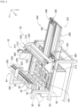
- Component supply apparatus 88 has openings at the upper surface and front surface; the opening at the upper surface is component insertion opening 97 and the opening at the front surface is component discharge opening 98.
- inclined plate 104 is provided below insertion opening 97.
- Inclined plate 104 is arranged across the entire width (X direction) of component supply apparatus 88 and is inclined from the rear end surface of component supply apparatus 88 towards the center such that the front end of inclined plate 104 is positioned lower than the rear end.
- Conveyor device 106 is arranged at the front side of inclined plate 104.
- Conveyor device 106 includes a pair of rollers 108 and 110, and conveyor belt 112.
- Each of the rollers 108 and 110 are arranged inside component supply apparatus 88 extending in the width direction of component supply apparatus 88 across the entire width of component supply apparatus 88.
- roller 108 faces the front end of inclined plate 104, that is, the lowest end of inclined plate 104, with a clearance gap between them. Note that, the clearance between the front end of inclined plate 104 and roller 108 is smaller than components that are supplied by component supply apparatus 88.
- roller 110 is arranged diagonally above and to the front of roller 108.
- Conveyor belt 112 is stretched over the pair of rollers 108 and 110. Note that, conveyor belt 112 has a width slightly less than the internal width dimension of component supply apparatus 88.
- pair of side frame sections 130 are assembled on base 96.
- the pair of side frame sections 130 are parallel to each other and are arranged upright extending in the Y direction.
- the distance between the pair of side frame sections 130 is slightly larger than the width dimension of component supply apparatus 88, with component supply apparatus 88 being detachably mounted between the pair of side frame sections 130.
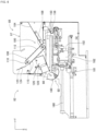
- Component scattering device 90 includes component support member 150 and component support member moving device 152.
- Component support member 150 is configured from stage 156 and pair of side walls 158.
- Stage 156 is a substantially rectangular plate and is arranged extending forwards from below component supply apparatus 88 mounted between pair of side frame sections 130. Note that, the upper surface of stage 156 is substantially horizontal and, as shown in fig. 5 , is arranged with a small clearance gap from the bent front end of inclined plate 128 of component supply apparatus 88.
- pair of side walls 158 is fixed upright at both ends of stage 156 in the lengthwise direction, with the upper end of each side wall 158 extending above the upper surface of stage 156.
- imaging device 84 includes camera 290 and camera moving device 292.
- Camera moving device 292 includes guide rail 296 and slider 298.
- Guide rail 296 is fixed to main body 80 above component supply apparatus 88 so as to extend in the width direction (X direction) of loose component supply device 32.
- Slider 298 is slidably attached to guide rail 296, and can be slid to any position by operation of electromagnetic motor 299 (refer to fig. 12 ).
- camera 290 is attached to slider 298 facing downwards.
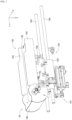
- component transfer device 86 includes component holding head moving device 300, component holding head 302, and two shuttle devices 304.
- Holder 340 is able to bend at support shaft 344, and holder 340 bends 90 degrees in an up direction by operation of pivoting device 334.
- chuck 332 attached to the bottom end of holder 340 is pivoted 90 degrees to be positioned at the pivoted position. That is, chuck 332 is able to be pivoted to and from a non-pivoted position and a pivoted position by operation of pivoting device 334.
- rotating device 335 rotates chuck 332 around its own center axis.
- each of the two shuttle devices 304 includes component carrier 388, and component carrier moving device 390, and is fixed to main body 80 lined up in the sideways direction on the front side of component supply unit 82.
- Five component receiving members 392 are attached to component carrier 388 lined up in a single row sideways, and components are loaded on each component receiving member 392.
- component carrier moving device 390 is a long plate member provided on the front side of component supply unit 82 and extending in the front-rear direction.
- Component carrier 388 is provided on the upper surface of component carrier moving device 390 to be slidable in the front-rear direction, and is slid to any position in the front-rear direction by operation of electromagnetic motor 430 (refer to fig. 12 ).
- component carrier 388 when slid in a direction approaching component supply unit 82, is slid to a component receiving position that is positioned within the movement range of component holding head 302 by component holding head moving device 300.
- component carrier 388 when slid in a direction away from component supply unit 82, component carrier 388 is slid to a component supply position that is positioned within the movement range of work heads 60 and 62 by work head moving device 64.
- control device 34 includes overall control device 450, multiple individual control devices (only one is shown in the figure) 452, image processing device 454, and memory device 456.
- Overall control device 450 is configured mainly from a computer and is connected to board conveying and holding device 22, component mounting device 24, imaging device 26, imaging device 28, component supply device 30, and loose component supply device 32.
- overall control device 450 performs overall control of board conveying and holding device 22, component mounting device 24, imaging device 26, imaging device 28, component supply device 30, and loose component supply device 32.
- component collection container 180 positioned at the front end of component support member 150 is positioned in front of component supply apparatus 88, and the opening of component collection container 180 is oriented facing up (collection orientation, refer to fig. 7 ).
- Leaded components 410 inserted via insertion opening 97 on the top surface of component supply apparatus 88 fall onto inclined plate 104 of component supply apparatus 88 and roll down to the front lower end of inclined plate 104.
- leaded components 410 that have rolled down to the front bottom end of inclined plate 104 pile up between the front bottom end of inclined plate 104 and the rear bottom end of conveyor device 106.
- housing section 100 for housing leaded components 410 between the lower front end of inclined plate 104 and the lower rear end of conveyor device 106 functions as housing section 100 for housing leaded components 410.
- rotation device 116 of conveyor device 106 is operated, conveyor belt 112 of conveyor device 106 is rotated counterclockwise as shown in fig. 6 .
- leaded components 410 piled up in housing section 100 are conveyed by conveyor belt 112 diagonally up and forward.
- leaded components 410 conveyed diagonally up by conveyor belt 112 pass between the upper end on the front side of conveyance device 106 and brush 124 and fall onto inclined plate 120 provided below the upper end on the front side of conveyance device 106 and brush 124.
- Leaded components 410 that have fallen onto inclined plate 126 roll towards the rear of inclined plate 126 onto inclined plate 128 provided below inclined plate 126.
- leaded components 410 that have fallen onto inclined plate 128 roll towards the front and are discharged from discharge opening 98 at the front of component supply apparatus 88.
- leaded components 410 that have fallen from the front end of conveyor device 106 fall onto inclined plate 126 and then onto inclined plate 128. That is, leaded components 410 are discharged from discharge opening 98 of component supply apparatus 88. By this, damage to leaded components 410 due to falling is reduced.
- Leaded components 410 that have been discharged onto stage 156 from component supply apparatus 88 roll forward, though even if they roll and fall from the front of stage 156 they are stored in component collection container 180. Also, if leaded components 410 that have been discharged onto stage 156 from component supply apparatus 88 roll sideways, they are prevented from falling from stage 156 by side walls 158 of component support member 150.
- component support member 150 is moved forwards from the stored state to the exposed state and then movement of component support member 150 is stopped. By this, leaded components 410 are scattered across the entire upper surface of stage 156. With component supply apparatus 88, operation of conveyor device 106 is stopped to match the timing of the stopping of the operation of component support member 150 such that leaded components 410 are discharged finally from component supply apparatus 88.
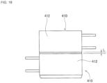
- leaded components 410 are scattered on stage 156 of component support member 150 from component storage apparatus 88, as shown in fig. 13 , leaded components 410 are scattered on stage 156 in largely three orientations. Specifically, leaded components 410 are scattered on stage 156 in the following three orientations: an orientation in which the two leads 414 are in a state approximately lined up in a horizontal direction (also referred to as a "first orientation”); an orientation in which the surface from which the leads 414 extend faces sideways and the two leads 414 are in a state approximately lined up in a vertical direction (also referred to as a "second orientation”); and an orientation in which the surface from which the leads 414 extend faces upwards (also referred to as a "third orientation”). Note that, when distinguishing between orientations of scattered leaded components 410, components are given as leaded component 410a in a first orientation, leaded component 410b in a second orientation, and leaded component 410c in a third orientation.
- holding-not-possible range 460 is set at a location separated by a set distance from the outer edge lines of component main body 412 of leaded component 410 set as the pickup target component. Also, it is determined whether there is another leaded component 410 or the like in the holding-not-possible range 460 of the leaded component 410 set as the pickup target, and if it is determined that there is another leaded component or the like in the holding-not-possible range 460, the setting of that component as the pickup target component is canceled. On the other hand, if it is determined that there is no other leaded component 410 or the like in the holding-not-possible range 460, the setting of that component as the pickup target component is left unchanged. Thus, there is no danger of chuck 332 interfering with other items during pickup, and pickup can be performed appropriately.
- main light beam 470 is a light beam that passes through the focal center of a lens of camera 290 during imaging.
- the light beam reflected by the side surface of leaded component 410 enters camera 290 and the side surface of the leaded component 410 is imaged.
- the viewing angle is 0, so the main light beam and the light axis are parallel, meaning that the side surface of leaded component 410 is not captured during imaging of leaded component 410.
- component main body 412 is cuboid, in a case in which there is no other leaded component 410 within the holding-not-possible range 460 based on the upper surface of component main body 412, when that component main body 412 is held by a chuck, there will be no interference with another leaded component 410.
- leaded component 410 determined based on holding-not-possible range 460 set based on the outer edge lines of component main body 412 has its setting as the pickup target component canceled.
- the component is not set as a pickup target component and remains on stage 156. In this manner, components that could be picked up remain on stage 156, thus worsening the efficiency of component pickup.
- the bottom right of fig. 13 shows scattered leaded components 410 in an overlapping state.
- the leaded component 410 that is on top of another leaded component 410 may be positioned above the planned pickup position, it may not be possible to perform pickup appropriately.
- such a leaded component 410 should not be set as a pickup target component.
- the outer edge lines of the leaded component 410 are slightly smaller, while the shape of the outer edge lines are substantially the same, meaning that the component may be set as a pickup target component.
- the size of the side surface differs greatly in accordance with the height of the imaged leaded component 410.
- the higher the imaging position is moved the larger the image dimension of the side surface of the leaded component 410 becomes, in which case, the length of the side surface of the leaded component 410 calculated based on the image data of the leaded component 410, that is, the calculated side surface length L, becomes longer. Therefore, in a case in which the leaded component 410 is positioned higher than the planned pickup position, calculated side surface length L and the estimated side surface length are different. In other words, by canceling the set of the component as a pickup target component when the calculated side surface length L and the estimated side surface length are different, it is possible to exempt leaded components 410 in an overlapping state from being set as a pickup target component.
- the estimated side surface length is set based on the parallax that arises between the deviation in the light axis of camera 290 and the main light beam. Specifically, as shown in fig. 20 , the further the distance from light axis 472, the larger the angle of main light beam 470. Therefore, with an image formed by reflection from the side surface of leaded component 410 of main light beam 470 that enters camera 290, the further the position of leaded component 410 away from light axis 472, the larger the image of the side surface of the leaded component 410.
- the image dimension of the side surface of the leaded component 410 positioned further from light axis 472 (S4) is larger than the image dimension of the side surface of the leaded component 410 positioned closer to light axis 472 (S3).
- the relationship between the positional deviation of black circles 482 and the height of the imaging position of plate 480 is calculated, and the estimated side surface length is calculated based on the thickness of leaded component 410, that is, the height of the side surface of the leaded component 410 scattered on stage 156 in the first orientation or the second orientation.
- L the position deviation amount of black circle 482
- H the imaging position height of plate 480
- the set pickup target component is held by chuck 332.
- chuck 332 is positioned in the non-pivoted position. Then, after holding leaded component 410 using chuck 332, component holding head 302 is moved above component carrier 388. Then, component carrier 388 is moved to the component receiving position by operation of component carrier moving device 390. Also, when component holding head 302 is moved above component carrier 388, chuck 332 is pivoted to the pivoted position. Note that, chuck 332 is rotated by operation of rotating device 335 such that leads 414 of the leaded component 410 held by chuck 332 that is in the pivoted position face downwards in a vertical direction.
- leaded component 410 When component holding head 302 is moved above component carrier 388, leaded component 410 in a state with leads 414 facing downwards in the vertical direction is inserted into component reception recess 416 of component reception member 392. By this, as shown in fig. 11 , leaded component 410 is loaded in component receiving member 392 with leads 414 facing vertically downwards.
- component support member 150 when leaded components 410 are collected in component collection container 180, those leaded components 410 are scattered onto stage 156.
- component support member 150 is in the stored state. Also, component support member 150 is moved from the stored state towards the front by the operation of component support member moving device 152. Next, when component support member 150 has been moved forward from the stored state by a specified amount, container swinging device 181 of component returning device 92 is operated and component collection container 180 is swung. Note that, movement of component support member 150 does not stop even when component collection container 180 swings. That is, component collection apparatus 180 swings while component support member 150 is moving.
- the present invention is applied to leaded components, but the present invention may be applied to various types of components. Specifically, for example, the present invention may be applied to configuration components of solar panels, configuration components of power modules, electronic components without leads, and so on. Also, as well as using chuck 332 as a holding tool for holding a component, various holding tools such as a suction nozzle may be used.
Applications Claiming Priority (1)
| Application Number | Priority Date | Filing Date | Title |
|---|---|---|---|
| PCT/JP2016/077919 WO2018055713A1 (ja) | 2016-09-22 | 2016-09-22 | 部品供給システム |
Publications (3)
| Publication Number | Publication Date |
|---|---|
| EP3518645A1 EP3518645A1 (en) | 2019-07-31 |
| EP3518645A4 EP3518645A4 (en) | 2019-10-16 |
| EP3518645B1 true EP3518645B1 (en) | 2023-02-22 |
Family
ID=61690292
Family Applications (1)
| Application Number | Title | Priority Date | Filing Date |
|---|---|---|---|
| EP16916782.2A Active EP3518645B1 (en) | 2016-09-22 | 2016-09-22 | Control method for a component supply system and component supply system for performing the control method |
Country Status (5)
| Country | Link |
|---|---|
| US (1) | US11122721B2 (zh) |
| EP (1) | EP3518645B1 (zh) |
| JP (1) | JP6754437B2 (zh) |
| CN (1) | CN109716878B (zh) |
| WO (1) | WO2018055713A1 (zh) |
Families Citing this family (5)
| Publication number | Priority date | Publication date | Assignee | Title |
|---|---|---|---|---|
| CN109196970B (zh) * | 2016-05-31 | 2020-11-20 | 株式会社富士 | 元件供给系统 |
| CN114287176B (zh) * | 2019-08-30 | 2024-03-12 | 株式会社富士 | 作业机 |
| CN110913682A (zh) * | 2019-11-29 | 2020-03-24 | 深圳市智微智能软件开发有限公司 | Smt换料方法及系统 |
| US20220394893A1 (en) * | 2019-12-16 | 2022-12-08 | Fuji Corporation | Component mounter |
| EP4322105A1 (en) * | 2021-04-06 | 2024-02-14 | Fuji Corporation | Storage device and method for updating image determination process stored in storage device |
Family Cites Families (15)
| Publication number | Priority date | Publication date | Assignee | Title |
|---|---|---|---|---|
| JPH0233670A (ja) * | 1988-07-25 | 1990-02-02 | Matsushita Electric Ind Co Ltd | 電子部品の認識方法 |
| US6056108A (en) * | 1997-11-17 | 2000-05-02 | Adept Technology, Inc. | Impulse-based, flexible parts feeder |
| JP4688377B2 (ja) * | 2000-09-26 | 2011-05-25 | パナソニック株式会社 | 部品実装方法 |
| JP2003148914A (ja) * | 2001-11-08 | 2003-05-21 | Fanuc Ltd | 位置検出装置及び位置検出を利用した取出し装置 |
| KR101398205B1 (ko) * | 2008-09-18 | 2014-05-21 | 삼성테크윈 주식회사 | 전자 부품 정보 인식 및 처리 장치 |
| JP5837065B2 (ja) | 2011-06-29 | 2015-12-24 | 三菱電機株式会社 | 部品供給装置 |
| JP5600705B2 (ja) * | 2012-05-10 | 2014-10-01 | ヤマハ発動機株式会社 | 部品実装装置 |
| JP6212330B2 (ja) * | 2013-08-29 | 2017-10-11 | 富士機械製造株式会社 | 部品トレー |
| US9949417B2 (en) * | 2013-12-27 | 2018-04-17 | Fuji Machine Mfg. Co., Ltd. | Component supply system |
| CN106465572B (zh) * | 2014-06-03 | 2019-10-22 | 株式会社富士 | 散装元件供给装置及元件安装装置 |
| JPWO2016046897A1 (ja) * | 2014-09-23 | 2017-06-29 | 富士機械製造株式会社 | 部品供給システム |
| JP6470935B2 (ja) * | 2014-09-29 | 2019-02-13 | Juki株式会社 | 電子部品実装装置 |
| CN111731835B (zh) * | 2014-11-06 | 2022-05-24 | 株式会社富士 | 元件供给装置 |
| EP3258762B1 (en) * | 2015-02-12 | 2019-12-04 | FUJI Corporation | Component supply device |
| JP6524250B2 (ja) * | 2015-10-15 | 2019-06-05 | ヤマハ発動機株式会社 | 部品実装装置 |
-
2016
- 2016-09-22 US US16/331,313 patent/US11122721B2/en active Active
- 2016-09-22 JP JP2018540545A patent/JP6754437B2/ja active Active
- 2016-09-22 CN CN201680089438.9A patent/CN109716878B/zh active Active
- 2016-09-22 EP EP16916782.2A patent/EP3518645B1/en active Active
- 2016-09-22 WO PCT/JP2016/077919 patent/WO2018055713A1/ja unknown
Also Published As
| Publication number | Publication date |
|---|---|
| WO2018055713A1 (ja) | 2018-03-29 |
| EP3518645A4 (en) | 2019-10-16 |
| US20190357396A1 (en) | 2019-11-21 |
| EP3518645A1 (en) | 2019-07-31 |
| US11122721B2 (en) | 2021-09-14 |
| JPWO2018055713A1 (ja) | 2019-06-27 |
| CN109716878A (zh) | 2019-05-03 |
| CN109716878B (zh) | 2021-02-09 |
| JP6754437B2 (ja) | 2020-09-09 |
Similar Documents
| Publication | Publication Date | Title |
|---|---|---|
| EP3518645B1 (en) | Control method for a component supply system and component supply system for performing the control method | |
| EP3468330B1 (en) | Component supply system | |
| EP3684156B1 (en) | Component feeding system | |
| EP3273759B1 (en) | Component supply device | |
| EP3468328B1 (en) | Component supply device | |
| EP3468329B1 (en) | Component supply apparatus | |
| JP6921234B2 (ja) | 部品供給装置及び、部品供給方法 | |
| US11388848B2 (en) | Component supply device | |
| EP3537862B1 (en) | Component supply system | |
| EP3544401B1 (en) | Operation machine | |
| US11510352B2 (en) | Component supply device | |
| JP7212663B2 (ja) | 部品供給システム | |
| JP2018079532A (ja) | 部品供給システム |
Legal Events
| Date | Code | Title | Description |
|---|---|---|---|
| STAA | Information on the status of an ep patent application or granted ep patent |
Free format text: STATUS: THE INTERNATIONAL PUBLICATION HAS BEEN MADE |
|
| PUAI | Public reference made under article 153(3) epc to a published international application that has entered the european phase |
Free format text: ORIGINAL CODE: 0009012 |
|
| STAA | Information on the status of an ep patent application or granted ep patent |
Free format text: STATUS: REQUEST FOR EXAMINATION WAS MADE |
|
| 17P | Request for examination filed |
Effective date: 20190311 |
|
| AK | Designated contracting states |
Kind code of ref document: A1 Designated state(s): AL AT BE BG CH CY CZ DE DK EE ES FI FR GB GR HR HU IE IS IT LI LT LU LV MC MK MT NL NO PL PT RO RS SE SI SK SM TR |
|
| AX | Request for extension of the european patent |
Extension state: BA ME |
|
| A4 | Supplementary search report drawn up and despatched |
Effective date: 20190912 |
|
| RIC1 | Information provided on ipc code assigned before grant |
Ipc: H05K 13/08 20060101ALI20190906BHEP Ipc: H05K 13/04 20060101ALI20190906BHEP Ipc: H05K 13/02 20060101AFI20190906BHEP |
|
| DAV | Request for validation of the european patent (deleted) | ||
| DAX | Request for extension of the european patent (deleted) | ||
| STAA | Information on the status of an ep patent application or granted ep patent |
Free format text: STATUS: EXAMINATION IS IN PROGRESS |
|
| 17Q | First examination report despatched |
Effective date: 20210217 |
|
| STAA | Information on the status of an ep patent application or granted ep patent |
Free format text: STATUS: EXAMINATION IS IN PROGRESS |
|
| GRAP | Despatch of communication of intention to grant a patent |
Free format text: ORIGINAL CODE: EPIDOSNIGR1 |
|
| STAA | Information on the status of an ep patent application or granted ep patent |
Free format text: STATUS: GRANT OF PATENT IS INTENDED |
|
| INTG | Intention to grant announced |
Effective date: 20220722 |
|
| GRAJ | Information related to disapproval of communication of intention to grant by the applicant or resumption of examination proceedings by the epo deleted |
Free format text: ORIGINAL CODE: EPIDOSDIGR1 |
|
| STAA | Information on the status of an ep patent application or granted ep patent |
Free format text: STATUS: EXAMINATION IS IN PROGRESS |
|
| INTC | Intention to grant announced (deleted) | ||
| GRAP | Despatch of communication of intention to grant a patent |
Free format text: ORIGINAL CODE: EPIDOSNIGR1 |
|
| STAA | Information on the status of an ep patent application or granted ep patent |
Free format text: STATUS: GRANT OF PATENT IS INTENDED |
|
| INTG | Intention to grant announced |
Effective date: 20221025 |
|
| GRAS | Grant fee paid |
Free format text: ORIGINAL CODE: EPIDOSNIGR3 |
|
| GRAA | (expected) grant |
Free format text: ORIGINAL CODE: 0009210 |
|
| STAA | Information on the status of an ep patent application or granted ep patent |
Free format text: STATUS: THE PATENT HAS BEEN GRANTED |
|
| AK | Designated contracting states |
Kind code of ref document: B1 Designated state(s): AL AT BE BG CH CY CZ DE DK EE ES FI FR GB GR HR HU IE IS IT LI LT LU LV MC MK MT NL NO PL PT RO RS SE SI SK SM TR |
|
| REG | Reference to a national code |
Ref country code: GB Ref legal event code: FG4D |
|
| REG | Reference to a national code |
Ref country code: CH Ref legal event code: EP |
|
| REG | Reference to a national code |
Ref country code: DE Ref legal event code: R096 Ref document number: 602016078008 Country of ref document: DE |
|
| REG | Reference to a national code |
Ref country code: AT Ref legal event code: REF Ref document number: 1550356 Country of ref document: AT Kind code of ref document: T Effective date: 20230315 Ref country code: IE Ref legal event code: FG4D |
|
| REG | Reference to a national code |
Ref country code: LT Ref legal event code: MG9D |
|
| P01 | Opt-out of the competence of the unified patent court (upc) registered |
Effective date: 20230328 |
|
| REG | Reference to a national code |
Ref country code: NL Ref legal event code: MP Effective date: 20230222 |
|
| REG | Reference to a national code |
Ref country code: AT Ref legal event code: MK05 Ref document number: 1550356 Country of ref document: AT Kind code of ref document: T Effective date: 20230222 |
|
| PG25 | Lapsed in a contracting state [announced via postgrant information from national office to epo] |
Ref country code: RS Free format text: LAPSE BECAUSE OF FAILURE TO SUBMIT A TRANSLATION OF THE DESCRIPTION OR TO PAY THE FEE WITHIN THE PRESCRIBED TIME-LIMIT Effective date: 20230222 Ref country code: PT Free format text: LAPSE BECAUSE OF FAILURE TO SUBMIT A TRANSLATION OF THE DESCRIPTION OR TO PAY THE FEE WITHIN THE PRESCRIBED TIME-LIMIT Effective date: 20230622 Ref country code: NO Free format text: LAPSE BECAUSE OF FAILURE TO SUBMIT A TRANSLATION OF THE DESCRIPTION OR TO PAY THE FEE WITHIN THE PRESCRIBED TIME-LIMIT Effective date: 20230522 Ref country code: NL Free format text: LAPSE BECAUSE OF FAILURE TO SUBMIT A TRANSLATION OF THE DESCRIPTION OR TO PAY THE FEE WITHIN THE PRESCRIBED TIME-LIMIT Effective date: 20230222 Ref country code: LV Free format text: LAPSE BECAUSE OF FAILURE TO SUBMIT A TRANSLATION OF THE DESCRIPTION OR TO PAY THE FEE WITHIN THE PRESCRIBED TIME-LIMIT Effective date: 20230222 Ref country code: LT Free format text: LAPSE BECAUSE OF FAILURE TO SUBMIT A TRANSLATION OF THE DESCRIPTION OR TO PAY THE FEE WITHIN THE PRESCRIBED TIME-LIMIT Effective date: 20230222 Ref country code: HR Free format text: LAPSE BECAUSE OF FAILURE TO SUBMIT A TRANSLATION OF THE DESCRIPTION OR TO PAY THE FEE WITHIN THE PRESCRIBED TIME-LIMIT Effective date: 20230222 Ref country code: ES Free format text: LAPSE BECAUSE OF FAILURE TO SUBMIT A TRANSLATION OF THE DESCRIPTION OR TO PAY THE FEE WITHIN THE PRESCRIBED TIME-LIMIT Effective date: 20230222 Ref country code: AT Free format text: LAPSE BECAUSE OF FAILURE TO SUBMIT A TRANSLATION OF THE DESCRIPTION OR TO PAY THE FEE WITHIN THE PRESCRIBED TIME-LIMIT Effective date: 20230222 |
|
| PG25 | Lapsed in a contracting state [announced via postgrant information from national office to epo] |
Ref country code: SE Free format text: LAPSE BECAUSE OF FAILURE TO SUBMIT A TRANSLATION OF THE DESCRIPTION OR TO PAY THE FEE WITHIN THE PRESCRIBED TIME-LIMIT Effective date: 20230222 Ref country code: PL Free format text: LAPSE BECAUSE OF FAILURE TO SUBMIT A TRANSLATION OF THE DESCRIPTION OR TO PAY THE FEE WITHIN THE PRESCRIBED TIME-LIMIT Effective date: 20230222 Ref country code: IS Free format text: LAPSE BECAUSE OF FAILURE TO SUBMIT A TRANSLATION OF THE DESCRIPTION OR TO PAY THE FEE WITHIN THE PRESCRIBED TIME-LIMIT Effective date: 20230622 Ref country code: GR Free format text: LAPSE BECAUSE OF FAILURE TO SUBMIT A TRANSLATION OF THE DESCRIPTION OR TO PAY THE FEE WITHIN THE PRESCRIBED TIME-LIMIT Effective date: 20230523 Ref country code: FI Free format text: LAPSE BECAUSE OF FAILURE TO SUBMIT A TRANSLATION OF THE DESCRIPTION OR TO PAY THE FEE WITHIN THE PRESCRIBED TIME-LIMIT Effective date: 20230222 |
|
| PG25 | Lapsed in a contracting state [announced via postgrant information from national office to epo] |
Ref country code: SM Free format text: LAPSE BECAUSE OF FAILURE TO SUBMIT A TRANSLATION OF THE DESCRIPTION OR TO PAY THE FEE WITHIN THE PRESCRIBED TIME-LIMIT Effective date: 20230222 Ref country code: RO Free format text: LAPSE BECAUSE OF FAILURE TO SUBMIT A TRANSLATION OF THE DESCRIPTION OR TO PAY THE FEE WITHIN THE PRESCRIBED TIME-LIMIT Effective date: 20230222 Ref country code: EE Free format text: LAPSE BECAUSE OF FAILURE TO SUBMIT A TRANSLATION OF THE DESCRIPTION OR TO PAY THE FEE WITHIN THE PRESCRIBED TIME-LIMIT Effective date: 20230222 Ref country code: DK Free format text: LAPSE BECAUSE OF FAILURE TO SUBMIT A TRANSLATION OF THE DESCRIPTION OR TO PAY THE FEE WITHIN THE PRESCRIBED TIME-LIMIT Effective date: 20230222 Ref country code: CZ Free format text: LAPSE BECAUSE OF FAILURE TO SUBMIT A TRANSLATION OF THE DESCRIPTION OR TO PAY THE FEE WITHIN THE PRESCRIBED TIME-LIMIT Effective date: 20230222 |
|
| REG | Reference to a national code |
Ref country code: DE Ref legal event code: R097 Ref document number: 602016078008 Country of ref document: DE |
|
| PG25 | Lapsed in a contracting state [announced via postgrant information from national office to epo] |
Ref country code: SK Free format text: LAPSE BECAUSE OF FAILURE TO SUBMIT A TRANSLATION OF THE DESCRIPTION OR TO PAY THE FEE WITHIN THE PRESCRIBED TIME-LIMIT Effective date: 20230222 |
|
| PGFP | Annual fee paid to national office [announced via postgrant information from national office to epo] |
Ref country code: DE Payment date: 20230802 Year of fee payment: 8 |
|
| PLBE | No opposition filed within time limit |
Free format text: ORIGINAL CODE: 0009261 |
|
| STAA | Information on the status of an ep patent application or granted ep patent |
Free format text: STATUS: NO OPPOSITION FILED WITHIN TIME LIMIT |
|
| 26N | No opposition filed |
Effective date: 20231123 |
|
| PG25 | Lapsed in a contracting state [announced via postgrant information from national office to epo] |
Ref country code: SI Free format text: LAPSE BECAUSE OF FAILURE TO SUBMIT A TRANSLATION OF THE DESCRIPTION OR TO PAY THE FEE WITHIN THE PRESCRIBED TIME-LIMIT Effective date: 20230222 |