EP3518639B1 - Umrichter und verfahren zur steuerung davon - Google Patents
Umrichter und verfahren zur steuerung davon Download PDFInfo
- Publication number
- EP3518639B1 EP3518639B1 EP18174845.0A EP18174845A EP3518639B1 EP 3518639 B1 EP3518639 B1 EP 3518639B1 EP 18174845 A EP18174845 A EP 18174845A EP 3518639 B1 EP3518639 B1 EP 3518639B1
- Authority
- EP
- European Patent Office
- Prior art keywords
- inverter
- opening
- temperature
- closing part
- auxiliary
- Prior art date
- Legal status (The legal status is an assumption and is not a legal conclusion. Google has not performed a legal analysis and makes no representation as to the accuracy of the status listed.)
- Active
Links
Images





Classifications
-
- H—ELECTRICITY
- H05—ELECTRIC TECHNIQUES NOT OTHERWISE PROVIDED FOR
- H05K—PRINTED CIRCUITS; CASINGS OR CONSTRUCTIONAL DETAILS OF ELECTRIC APPARATUS; MANUFACTURE OF ASSEMBLAGES OF ELECTRICAL COMPONENTS
- H05K7/00—Constructional details common to different types of electric apparatus
- H05K7/20—Modifications to facilitate cooling, ventilating, or heating
- H05K7/2089—Modifications to facilitate cooling, ventilating, or heating for power electronics, e.g. for inverters for controlling motor
- H05K7/20945—Thermal management, e.g. inverter temperature control
-
- H—ELECTRICITY
- H02—GENERATION; CONVERSION OR DISTRIBUTION OF ELECTRIC POWER
- H02M—APPARATUS FOR CONVERSION BETWEEN AC AND AC, BETWEEN AC AND DC, OR BETWEEN DC AND DC, AND FOR USE WITH MAINS OR SIMILAR POWER SUPPLY SYSTEMS; CONVERSION OF DC OR AC INPUT POWER INTO SURGE OUTPUT POWER; CONTROL OR REGULATION THEREOF
- H02M7/00—Conversion of AC power input into DC power output; Conversion of DC power input into AC power output
- H02M7/003—Constructional details, e.g. physical layout, assembly, wiring or busbar connections
-
- H—ELECTRICITY
- H02—GENERATION; CONVERSION OR DISTRIBUTION OF ELECTRIC POWER
- H02M—APPARATUS FOR CONVERSION BETWEEN AC AND AC, BETWEEN AC AND DC, OR BETWEEN DC AND DC, AND FOR USE WITH MAINS OR SIMILAR POWER SUPPLY SYSTEMS; CONVERSION OF DC OR AC INPUT POWER INTO SURGE OUTPUT POWER; CONTROL OR REGULATION THEREOF
- H02M7/00—Conversion of AC power input into DC power output; Conversion of DC power input into AC power output
- H02M7/42—Conversion of DC power input into AC power output without possibility of reversal
- H02M7/44—Conversion of DC power input into AC power output without possibility of reversal by static converters
-
- H—ELECTRICITY
- H05—ELECTRIC TECHNIQUES NOT OTHERWISE PROVIDED FOR
- H05K—PRINTED CIRCUITS; CASINGS OR CONSTRUCTIONAL DETAILS OF ELECTRIC APPARATUS; MANUFACTURE OF ASSEMBLAGES OF ELECTRICAL COMPONENTS
- H05K7/00—Constructional details common to different types of electric apparatus
- H05K7/20—Modifications to facilitate cooling, ventilating, or heating
- H05K7/2089—Modifications to facilitate cooling, ventilating, or heating for power electronics, e.g. for inverters for controlling motor
- H05K7/209—Heat transfer by conduction from internal heat source to heat radiating structure
-
- H—ELECTRICITY
- H05—ELECTRIC TECHNIQUES NOT OTHERWISE PROVIDED FOR
- H05K—PRINTED CIRCUITS; CASINGS OR CONSTRUCTIONAL DETAILS OF ELECTRIC APPARATUS; MANUFACTURE OF ASSEMBLAGES OF ELECTRICAL COMPONENTS
- H05K7/00—Constructional details common to different types of electric apparatus
- H05K7/20—Modifications to facilitate cooling, ventilating, or heating
- H05K7/2089—Modifications to facilitate cooling, ventilating, or heating for power electronics, e.g. for inverters for controlling motor
- H05K7/20909—Forced ventilation, e.g. on heat dissipaters coupled to components
-
- H—ELECTRICITY
- H05—ELECTRIC TECHNIQUES NOT OTHERWISE PROVIDED FOR
- H05K—PRINTED CIRCUITS; CASINGS OR CONSTRUCTIONAL DETAILS OF ELECTRIC APPARATUS; MANUFACTURE OF ASSEMBLAGES OF ELECTRICAL COMPONENTS
- H05K7/00—Constructional details common to different types of electric apparatus
- H05K7/20—Modifications to facilitate cooling, ventilating, or heating
- H05K7/2089—Modifications to facilitate cooling, ventilating, or heating for power electronics, e.g. for inverters for controlling motor
- H05K7/20909—Forced ventilation, e.g. on heat dissipaters coupled to components
- H05K7/20918—Forced ventilation, e.g. on heat dissipaters coupled to components the components being isolated from air flow, e.g. hollow heat sinks, wind tunnels or funnels
Definitions
- the present invention relates to an inverter in which a cooling structure is improved.
- An inverter is a unit configured to change direct current (DC) power into alternating current (AC) power
- a converter is a unit configured to change AC power into DC power
- both of the units are generically referred to as inverters.
- FIG 1 is a side cross-sectional view illustrating a conventional inverter.
- a heat sink 20 for dissipating heat generated by a circuit is disposed under a middle case 10 in which the circuit is disposed, and the heat sink 20 is accommodated in a lower case 30 coupled to a lower side of the middle case 10.
- a main inlet hole 31 through which an external air is introduced may be formed in one side surface of the lower case 30, a main discharge hole 32 through which the introduced external air is discharged may be formed in the other side surface thereof, and the lower case 30 includes a fan 40 disposed adjacent to the main inlet hole 31 and configured to move air.
- a differential current relay (DCR) 5 which is relatively not sensitive to foreign materials in the circuit, may be disposed in the lower case 30, and
- EP2879476A1 discloses an electric apparatus comprising a fan for generating a first airflow, a component space containing a secondary electric component, a housing, one or more walls that separates the component space containing the secondary electric component from a first cooling element for preventing the first airflow from entering the component space, a second cooling element having a first end in the component space and a second end located outside of the component space for dissipating heat received from the secondary electric component to the first airflow.
- EP2843700A2 discloses an apparatus for cooling inverter, whereby an optimum heat radiation effect can be accomplished, because a flow part is divided in response to heat generation amount of an electric element arranged inside a housing to adjust an air flow.
- US2011/0199736A1 discloses an inverter device having a control unit, a capacitor, and a power unit that has six semiconductor devices.
- Each semiconductor device has a semiconductor module and a pair of heat sinks disposed in both sides of the semiconductor module, and the heat sinks are arranged in a ventilation path of cooling air, with which an accommodation chamber of a control unit communicates.
- a space in the lower case 30 is divided into a first space and a second space by a partition 50, and the heat sink 20 and the DCR 5 are disposed in the first space and the second space, respectively.
- An auxiliary inlet hole 51 through which air moved by the fan 40 is introduced is formed in the partition 50, and an auxiliary discharge hole 52 for discharging air through the main discharge hole 32 is formed in the partition 50.
- the conventional inverter has a structure in which air is forcibly introduced through one main inlet hole 31 formed in the lower case 30 by the fan 40, forcibly circulated in the first space and the second space formed in the lower case 30 by the partition 50, and discharged through one main discharge hole 32.
- the partition 50 since the partition 50 has to be formed in consideration of a structure for an air flow in the second space, the structure may be complex and the utilization of a space may be reduced.
- the present invention is directed to improving an air flow structure of a lower case of an inverter so as to improve driving efficiency and heat dissipation performance of a fan.
- FIG. 1 is a side cross-sectional view illustrating a conventional inverter
- FIG. 2 is a perspective view illustrating an inverter according to an embodiment of the present invention
- FIG. 3 is a side cross-sectional view of FIG. 2
- FIG. 4 is a perspective view illustrating the inverter in which an upper case, a main circuit, and a middle frame are removed according to the embodiment of the present invention
- FIG. 5 is a front view of FIG. 4
- FIG. 6 is a view illustrating the inverter in which elements are modularized according to the embodiment of the present invention.
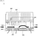
- FIG. 7 is a view illustrating an air flow state when an opening and closing part according to the embodiment of the present invention is closed
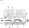
- FIG. 8 is a view illustrating an air flow state when the opening and closing part according to the embodiment of the present invention is opened.
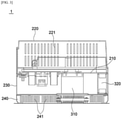
- an inverter 1 may mainly include a circuit 100, a main housing 200, an auxiliary housing 240, and a driver 300.
- the circuit 100 may be mainly divided into a main circuit 110 and an auxiliary circuit 120, and such division may be distinguished depending on whether the main circuit 110 or the auxiliary circuit 120 may be disposed in the auxiliary housing 240 which will be described below.
- the main circuit 110 is disposed in an upper case 220 which will be described below.
- the main circuit 110 may include a switching element, for example, a transistor, a thyristor, a power transistor, or an insulated gate bipolar transistor (IGBT) configured to switch direct current (DC) power into high frequency power.
- a switching element for example, a transistor, a thyristor, a power transistor, or an insulated gate bipolar transistor (IGBT) configured to switch direct current (DC) power into high frequency power.
- IGBT insulated gate bipolar transistor
- the auxiliary circuit 120 is an element, which generates relatively low heat and is hardly influenced by foreign materials, and is disposed in the auxiliary housing 240 so as to be exposed at the outside for natural ventilation.
- the auxiliary circuit 120 may include a differential current relay (DCR) or an electromagnetic compatibility (EMC) filter, and the like.
- a controller 130 may be disposed in the main circuit 110 or the auxiliary circuit 120, and control of the controller 130 will be described below.
- the main housing 200 accommodates the main circuit 110, and a first vent hole 231 may be formed in a lower end portion of one side surface of the main housing 200.
- the main housing 200 may sequentially mainly include a middle frame 210, the upper case 220, and a lower case 230.
- the middle frame 210 is substantially formed in a plate shape, and the main circuit 110 is disposed at an upper side of the middle frame 210, and a heat sink 310 is coupled to a lower side of the middle frame 210.
- the upper case 220 is a cover disposed above the middle frame 210 and configured to accommodate the main circuit 110.
- a plurality of upper vent holes 221 for natural heat dissipation may be formed at least one side surface of the upper case 220.
- the lower case 230 forms a space in which the heat sink 310 of the driver 300, which will be described below, is accommodated and a fan 320 is disposed.
- the lower case 230 may be disposed under the middle frame 210.
- first vent hole 231 may be formed in one side surface of the lower case 230.
- the first vent hole 231 may be an inlet for external air or outlet for internal air according to normal or reverse rotation of the fan 320.
- a plurality of first vent holes 231 may be formed in the one side surface of the lower case 230.
- the auxiliary housing 240 is disposed under the lower case 230 and accommodates the auxiliary circuit 120, and a second vent hole 241 may be formed in at least one side surface of the auxiliary housing 240.
- a plurality of second vent holes 241 may be formed in at least one side surface of the auxiliary housing 240.
- the second vent holes 241 may be formed in all surfaces of the auxiliary housing 240 as illustrated in the drawings.
- n n th auxiliary housings may be further provided under the auxiliary housing 240, and the n th auxiliary housings may be formed to be the same as the auxiliary housing 240.
- opening and closing parts 330 may be disposed in the n th auxiliary housings so that air may be ultimately forcibly moved by the fan 320.
- the upper vent hole 221, the first vent hole 231, and/or the second vent hole 241 may have a long hole shape perpendicular to the surface of the ground or a rectangular shape of which a long side is parallel to the surface of the ground. Accordingly, the same amount of air may be introduced into and discharged from the same space so that the heat sink 310 or DCR disposed in the auxiliary housing 240 may be effectively cooled.
- the driver 300 may include the heat sink 310, the fan 320, the opening and closing part 330, and a temperature sensor 340, and may further include an auxiliary fan 350 which is not shown.
- the heat sink 310 may be disposed in the middle frame 210, be accommodated in the lower case 230, and absorb heat generated when the main circuit 110 is driven to dissipate the heat.
- the heat sink 310 may roughly include a heat dissipation plate and a plurality of heat dissipation fins disposed on the heat dissipation plate.
- the heat sink 310 may be interposed between the first vent hole 231 formed in the one side surface of the lower case 230 and the fan 320 to effectively dissipate heat with an air flow generated by the fan 320.
- the fan 320 is disposed on the other side surface of the lower case 230 facing the first vent hole 231, and two fans 320 may be disposed in parallel as illustrated in the drawings. However, the number of the fans 320 may be easily increased or decreased according to an extent of heat generation of the circuit 100.
- normal or reverse rotation and a rotational speed of the fan 320 may be controlled by the controller 130.
- the fan 320 rotates such that the first vent hole 231 becomes an inlet through which external air is introduced.
- the opening and closing part 330 is interposed between the main housing 200 and the auxiliary housing 240 and controlled to be opened so that the main housing 200 communicates with the auxiliary housing 240.
- At least one opening and closing part 330 may be disposed on a bottom surface of the lower case 230 or an upper surface of the auxiliary housing 240. By opening the opening and closing part 330, an inside of the lower case 230 may communicate with an inside of the auxiliary housing 240.
- opening and closing part 330 may be opened or closed by control of the controller 130, or manually opened or closed.
- opening and closing part 330 may be interposed between the first vent hole 231 and the heat sink 310 or between the heat sink 310 and the fan 320.
- opening and closing part 330 may also be disposed on the entire bottom surface of the lower case 230 or the entire upper surface of the auxiliary housing 240.
- the opening and closing part 330 disposed in the lower case 230 interposed between the fan 320 and the heat sink 310 may be most efficient in terms of a hydromechanical relation with the driving force of the fan 320.
- the auxiliary circuit 120 for example, the DCR, may be disposed at a location corresponding to the heat sink 310 to more efficiently transmit heat.
- the temperature sensor 340 may be disposed in the auxiliary housing 240, measure a temperature of the inside of the auxiliary housing 240, and transmit information on the temperature to the controller 130.
- the temperature sensor 340 is disposed to measure an amount of heat generated by the auxiliary circuit 120 in the auxiliary housing 240 so as to open the opening and closing part 330. Accordingly, the temperature sensor 340 may also directly measure a temperature of the auxiliary circuit 120.
- the temperature sensor 340 may be disposed in the upper case 220, measure a temperature of an inside of the upper case 220, and transmit information on the temperature to the controller 130.
- the temperature sensor 340 is disposed to measure an amount of heat generated by the main circuit 110 in the upper case 220 so as to open the opening and closing part 330. Accordingly, the temperature sensor 340 may also directly measure a temperature of the main circuit 110.
- the temperature sensor 340 may be disposed at each of the inside of the upper case 220 and the inside of the auxiliary housing 240. Accordingly, the controller 130 receives the temperature of each of the inside of the upper case 220 and the inside of the auxiliary housing 240 from the temperature sensor 340 to selectively open the opening and closing part 330.
- the temperature sensor 340 may be disposed in the lower case 230.
- the controller 130 may open the opening and closing part 330 when a temperature of the inside of the lower case 230 is a preset temperature or lower.
- an auxiliary fan 350 may be disposed at one side of the auxiliary housing 240 like the auxiliary fan 350 disposed in the lower case 230. In this case, the opening and closing part 330 is not opened.
- FIG. 9 is a flowchart of a control method of the inverter according to the embodiment of the present invention.
- a control method of the inverter 1 according to the embodiment of the present invention and control of the controller 130 will be described below with reference to FIG. 9 .
- the heat transmitted to the heat sink 310 is dissipated from the lower case 230 by rotation of the fan 320 controlled by the controller 130 (S10).
- the heat of the inside of the lower case 230 is dissipated by air forcibly circulated by the fan 320.
- heat may be generated by the auxiliary circuit 120, for example, the DCR disposed in the auxiliary housing 240 according to driving of the auxiliary circuit 120.
- the heat generated by the auxiliary circuit 120 is naturally dissipated due to the second vent hole 241 formed in the at least one side surface of the auxiliary housing 240.
- FIG. 7 An air flow in a state in which the opening and closing part 330 is closed is illustrated in FIG. 7 .
- Black arrows denote an air flow in the lower case 230
- gray arrows denote an air flow in the auxiliary housing 240.
- the temperature sensor 340 senses a temperature of the inside of the auxiliary housing 240 or a temperature of the auxiliary circuit 120 disposed in the auxiliary housing 240 (S20).
- the controller 130 may open the opening and closing part 330 disposed on the bottom surface of the lower case 230 or the upper surface of the auxiliary housing 240 (S40).
- the opening and closing part 330 is opened and then an air flow in the inside of the auxiliary housing 240 is affected by air forcibly moved by the fan 320, and thus cooling efficiency of the auxiliary circuit 120 may be improved.
- the controller 130 may control a rotational speed of the fan 320 according to an output current value of the circuit 100 or an opening extent of the opening and closing part 330 (S50).
- controller 130 may differently control an opening or closing rate of the opening and closing part 330 according to a change in temperature.
- the controller 130 starts to open the opening and closing part 330 when the temperature of the inside of the auxiliary housing 240 measured by the temperature sensor 340 is higher than or equal to a first set temperature which is preset.
- the controller 130 completely opens the opening and closing part 330 in a case in which the temperature of the inside of the auxiliary housing 240 measured by the temperature sensor 340 is higher than or equal to a second set temperature which is preset.
- the controller 130 may control an opening rate of the opening and closing part 330 according to an increase rate of temperature when the measured temperature ranges from the first set temperature to the second set temperature.
- the controller 130 may open the opening and closing part 330 by only 10%.
- the controller 130 may open the opening and closing part 330 by 100%.
- the controller 130 may open the opening and closing part 330 by 50%.
- the controller 130 may also control some opening and closing parts 330 to be opened and control the remaining opening and closing parts 330 not to be opened.
- a main heat source is the main circuit 110 disposed in the upper case 220. Accordingly, the controller 130 may close a part or entirety of the opening and closing part 330 in a case in which a temperature of the upper case 220 increases to the preset temperature or higher after the opening and closing part 330 is opened.
- the controller 130 may open the opening and closing part 330 to naturally cool the lower case 230 like the auxiliary housing 240. In addition, the controller 130 may lightly drive the fan 320 to dissipate heat of the lower case 230 with small movement of air.
- FIG. 8 An air flow in a state in which the opening and closing part 330 is opened is illustrated in FIG. 8 , black arrows denote an air flow in the lower case 230, and gray arrows denote an air flow in the auxiliary housing 240.
- the temperature sensor 340 may sense a temperature of the upper case 220 (S60). In a case in which the temperature of the upper case 220 increases to the preset temperature or higher (S70), the controller 130 may close a part or entirety of the opening and closing part 330 to suppress an increase in temperature of the main circuit 110 (S80).
- the controller 130 may accordingly control the rotational speed of the fan 320 (S90).
- the inverter 1 normally forcibly cools the heat sink 310 disposed in the lower case 230 to dissipate heat of the main circuit 110 using the fan 320.
- the auxiliary housing 240 in which the auxiliary circuit 120 is disposed is naturally cooled, cooling efficiency and driving efficiency of the fan 320 are improved.
- the controller 130 opens the part or entirety of the opening and closing part 330, and increases the rotational speed of the fan 320. Accordingly, since a cooling speed may increase, there is an advantage in that cooling efficiency and economical use of the fan 320 are improved.
Landscapes
- Engineering & Computer Science (AREA)
- Microelectronics & Electronic Packaging (AREA)
- Physics & Mathematics (AREA)
- Thermal Sciences (AREA)
- Power Engineering (AREA)
- Inverter Devices (AREA)
- Cooling Or The Like Of Electrical Apparatus (AREA)
Claims (14)
- Wechselrichter (1), umfassend:ein Hauptgehäuse (200), das so konfiguriert ist, dass es einen Hauptstromkreis (110) aufnimmt, und das ein erstes Entlüftungsloch (231) beinhaltet, das in einem unteren Endabschnitt von einer Seitenfläche davon ausgebildet ist; einen Lüfter (320), der an der anderen Seitenfläche des Hauptgehäuses (200) dem ersten Entlüftungsloch (231) zugewandt angeordnet ist;einen Kühlkörper (310), der zwischen dem ersten Entlüftungsloch (231) und dem Lüfter (320) eingefügt ist; ein unter dem Hauptgehäuse (200) angeordnetes Hilfsgehäuse (240), das konfiguriert ist, einen Hilfsstromkreis (120) aufzunehmen, und ein zweites Entlüftungsloch (241) beinhaltet, das in zumindest einer Seitenfläche davon ausgebildet ist; undeine Steuerung (130), die in dem Hauptstromkreis (110) oder dem Hilfsstromkreis (120) angeordnet ist,wobei der Wechselrichter (1) gekennzeichnet ist durch:
zumindest einen Öffnungs- und Schließteil (330), der zwischen dem Hauptgehäuse (200) und dem Hilfsgehäuse (240) eingefügt ist und konfiguriert ist, geöffnet zu werden, sodass das Hauptgehäuse (200) in Verbindung mit dem Hilfsgehäuse (240) steht. - Wechselrichter (1) nach Anspruch 1, wobei das Hauptgehäuse (200) Folgendes beinhaltet:einen mittleren Rahmen (210), in dem der Hauptstromkreis (110) angeordnet ist;ein oberes Gehäuse (220), das über dem mittleren Rahmen (210) angeordnet ist und so konfiguriert ist, dass es den Hauptstromkreis (110) aufnimmt; undein unteres Gehäuse (230), das unter dem mittleren Rahmen (210) angeordnet ist und in dessen einer Seitenfläche das erste Entlüftungsloch (231) ausgebildet ist.
- Wechselrichter (1) nach Anspruch 2, wobei:eine Vielzahl von ersten Entlüftungslöchern, die identisch zu dem ersten Entlüftungsloch (231) sind, in der einen Seitenfläche des unteren Gehäuses (230) ausgebildet sind; undeine Vielzahl von zweiten Entlüftungslöchern, die identisch zu dem zweiten Entlüftungsloch (241) sind, in der zumindest einen Seitenfläche des Hilfsgehäuses (240) ausgebildet sind.
- Wechselrichter (1) nach Anspruch 1, wobei das zweite Entlüftungsloch (241) in jeder der Seitenflächen des Hilfsgehäuses (240) ausgebildet ist.
- Wechselrichter (1) nach Anspruch 1 bis 5, wobei sich der Lüfter (320) derart dreht, dass das erste Entlüftungsloch (231) zu einem Einlass wird, durch den Außenluft eingeleitet wird.
- Wechselrichter (1) nach Anspruch 1, wobei der Öffnungs- und Schließteil (330) durch Steuerung seitens der Steuerung (130) geöffnet oder geschlossen oder manuell geöffnet oder geschlossen wird.
- Wechselrichter (1) nach Anspruch 1, wobei:das Hilfsgehäuse (240) ferner einen Temperatursensor (340) beinhaltet, der so konfiguriert ist, dass er in Verbindung mit der Steuerung (130) arbeitet; unddie Steuerung (130) den Öffnungs- und Schließteil (330) öffnet, wenn eine Temperatur eines Innenraums des Hilfsgehäuses (240), die durch den Temperatursensor (340) gemessen wird, eine voreingestellte Temperatur ist.
- Wechselrichter (1) nach Anspruch 7, wobei die Steuerung 130:beginnt, den Öffnungs- und Schließteil (330) in einem Fall zu öffnen, in dem die Temperatur des Innenraums des Hilfsgehäuses (240), die durch den Temperatursensor (340) gemessen wird, höher als oder gleich eine erste Solltemperatur ist, die voreingestellt ist;den Öffnungs- und Schließteil (330) vollständig in einem Fall öffnet, in dem die Temperatur des Innenraums des Hilfsgehäuses (240), die durch den Temperatursensor 340 gemessen wird, höher als oder gleich eine zweite Solltemperatur ist, die voreingestellt ist; undeine Öffnungsrate des Öffnungs- und Schließteils (330) gemäß einer Anstiegsrate der Temperatur in einem Fall steuert, in dem die Temperatur des Innenraums des Hilfsgehäuses (240),die durch den Temperatursensor (340) gemessen wird, in einem Bereich von der ersten Solltemperatur zu der zweiten Solltemperatur liegt.
- Wechselrichter (1) nach Anspruch 1, wobei das Hauptgehäuse (200) Folgendes beinhaltet:einen mittleren Rahmen (210), in dem der Hauptstromkreis (110) angeordnet ist;ein oberes Gehäuse (220), das über dem mittleren Rahmen (210) angeordnet ist, das so konfiguriert ist, dass es den Hauptstromkreis (110) aufnimmt, und das einen Temperatursensor (340) beinhaltet, der so konfiguriert ist, dass er in Verbindung mit der Steuerung (130) arbeitet; undein unteres Gehäuse (230), das unter dem mittleren Rahmen (210) angeordnet ist und in dessen einer Seitenfläche das erste Entlüftungsloch (231) ausgebildet ist, wobei die Steuerung (130) den Öffnungs- und Schließteil (330) schließt, wenn eine Temperatur eines Innenraums des oberen Gehäuses (220), die durch den Temperatursensor (340) gemessen wird, eine voreingestellte Temperatur ist.
- Wechselrichter (1) nach Anspruch 1, wobei das Hauptgehäuse (200) Folgendes beinhaltet:einen mittleren Rahmen (210), in dem der Hauptstromkreis (110) angeordnet ist;ein oberes Gehäuse (220), das über dem mittleren Rahmen (210) angeordnet ist und so konfiguriert ist, dass es den Hauptstromkreis (110) aufnimmt; undein unteres Gehäuse (230), in dessen einer Seitenfläche das erste Entlüftungsloch (231) ausgebildet ist, das unter dem mittleren Rahmen (210) angeordnet ist, und das einen Temperatursensor (340) beinhaltet, der so konfiguriert ist, dass er in Verbindung mit der Steuerung (130) arbeitet, wobei die Steuerung (130) den Öffnungs- und Schließteil (330) öffnet, wenn eine Temperatur eines Innenraums des unteren Gehäuses (230), die durch den Temperatursensor (340) gemessen wird, eine voreingestellte Temperatur oder niedriger ist.
- Wechselrichter (1) nach Anspruch 1, wobei der Öffnungs- und Schließteil (330) zwischen dem ersten Entlüftungsloch (231) und dem Kühlkörper (310) oder zwischen dem Kühlkörper (310) und dem Lüfter (320) eingefügt ist.
- Wechselrichter (1) nach Anspruch 11, wobei ein Differenzstromrelais (DCR) an einer Stelle in dem Hilfsgehäuse (240) angeordnet ist, die dem Kühlkörper (310) entspricht.
- Wechselrichter (1) nach Anspruch 1, wobei die Steuerung (130) den Öffnungs- und Schließteil (330) öffnet, wenn ein Ausgangsstrom eines jeden von dem Hauptstromkreis (110) und dem Hilfsstromkreis (120) ein voreingestellter Stromwert oder höher ist.
- Wechselrichter (1) nach Anspruch 1, wobei die Steuerung (130) eine Drehzahl des Lüfters (320) gemäß einem Ausgangsstromwert eines jeden von dem Hauptstromkreis (110) und dem Hilfsstromkreis (120) oder einem Öffnungsgrad des Öffnungs- und Schließteils (330) steuert.
Applications Claiming Priority (1)
| Application Number | Priority Date | Filing Date | Title |
|---|---|---|---|
| KR1020180011279A KR102064247B1 (ko) | 2018-01-30 | 2018-01-30 | 인버터 및 이의 제어방법 |
Publications (2)
| Publication Number | Publication Date |
|---|---|
| EP3518639A1 EP3518639A1 (de) | 2019-07-31 |
| EP3518639B1 true EP3518639B1 (de) | 2022-01-19 |
Family
ID=62486467
Family Applications (1)
| Application Number | Title | Priority Date | Filing Date |
|---|---|---|---|
| EP18174845.0A Active EP3518639B1 (de) | 2018-01-30 | 2018-05-29 | Umrichter und verfahren zur steuerung davon |
Country Status (6)
| Country | Link |
|---|---|
| US (1) | US11013153B2 (de) |
| EP (1) | EP3518639B1 (de) |
| JP (1) | JP6517406B1 (de) |
| KR (1) | KR102064247B1 (de) |
| CN (1) | CN110098749B (de) |
| ES (1) | ES2908701T3 (de) |
Families Citing this family (9)
| Publication number | Priority date | Publication date | Assignee | Title |
|---|---|---|---|---|
| KR102081818B1 (ko) * | 2017-09-27 | 2020-02-27 | 한국원자력연구원 | 튜브 내면 코팅 방법 및 튜브 내면 코팅 장치 |
| CN214112314U (zh) * | 2020-10-16 | 2021-09-03 | 阳光电源股份有限公司 | 一种箱体以及充电桩 |
| CN112455214B (zh) * | 2020-12-04 | 2022-06-21 | 安徽江淮汽车集团股份有限公司 | 散热装置及汽车散热系统 |
| US12432890B2 (en) * | 2021-03-01 | 2025-09-30 | Weg Drives & Controls Automacao Ltda. | System and method for cooling a frequency inverter |
| US12213283B2 (en) * | 2021-07-20 | 2025-01-28 | Beijing Xiaomi Mobile Software Co., Ltd. | Electronic device and control method of electronic device |
| KR102654809B1 (ko) * | 2022-01-06 | 2024-04-03 | 엘에스일렉트릭(주) | 전력 변환 장치 |
| KR102597998B1 (ko) * | 2022-01-06 | 2023-11-02 | 엘에스일렉트릭(주) | 전력 변환 장치 |
| CN114727569A (zh) * | 2022-05-25 | 2022-07-08 | 冯小荣 | 一种辅助电源电路可自动断电的大功率逆变器 |
| KR102673106B1 (ko) * | 2022-07-06 | 2024-06-10 | 주식회사 경신 | 차량용 컨버터 냉각 시스템 및 그 방법 |
Family Cites Families (28)
| Publication number | Priority date | Publication date | Assignee | Title |
|---|---|---|---|---|
| US5905647A (en) * | 1997-01-20 | 1999-05-18 | Kabushiki Kaisha Toshiba | Inverter with incorporated filter circuit and improved component cooling arrangement |
| JP2005348533A (ja) * | 2004-06-03 | 2005-12-15 | Fuji Electric Fa Components & Systems Co Ltd | インバータ装置 |
| JP4639648B2 (ja) | 2004-06-03 | 2011-02-23 | 富士電機システムズ株式会社 | インバータ装置 |
| ES2377018T3 (es) | 2004-06-24 | 2012-03-21 | Sma Solar Technology Ag | Inversor con una carcasa con componentes eléctricos y/o electrónicos presentando disipadores de calor |
| US7205740B1 (en) * | 2006-03-17 | 2007-04-17 | Delta Elctronics, Inc. | Fan control device for frequency converter |
| DE202006008792U1 (de) | 2006-06-01 | 2007-10-04 | Diehl Ako Stiftung & Co. Kg | Solarwechselrichter |
| NZ551765A (en) * | 2006-12-01 | 2008-05-30 | Rayhill Ltd | Equipment cabinet |
| CN201478995U (zh) | 2009-08-12 | 2010-05-19 | 合肥阳光电源有限公司 | 一种大功率变流器电源柜的散热结构 |
| CN101764510B (zh) * | 2010-01-25 | 2012-05-30 | 苏州华辰电气有限公司 | 一种大功率变流器装置风冷散热结构 |
| JP2011167049A (ja) | 2010-02-15 | 2011-08-25 | Denso Corp | 電力変換装置 |
| JP5309089B2 (ja) | 2010-06-25 | 2013-10-09 | 株式会社日立製作所 | 電力変換装置および電力変換ユニットの冷却方法 |
| US8335081B2 (en) | 2010-07-16 | 2012-12-18 | Rockwell Automation Technologies, Inc. | Heat sink cooling arrangement for multiple power electronic circuits |
| CN201813311U (zh) * | 2010-08-11 | 2011-04-27 | 四方蒙华电(北京)自动化技术有限公司 | 一种风冷散热结构的兆瓦级风电变流器装置 |
| JP5348623B2 (ja) | 2010-09-10 | 2013-11-20 | 株式会社安川電機 | 電子機器装置 |
| JP5392581B2 (ja) * | 2011-04-14 | 2014-01-22 | 株式会社安川電機 | モータ制御装置及びそのブッシュ |
| JP5661055B2 (ja) | 2012-02-08 | 2015-01-28 | 三菱電機株式会社 | 制御装置 |
| JP5965779B2 (ja) | 2012-08-24 | 2016-08-10 | 株式会社日立産機システム | 電力変換装置 |
| CN202798511U (zh) | 2012-09-25 | 2013-03-13 | 广东易事特电源股份有限公司 | 具有改良散热风道的光伏逆变器机柜 |
| CN103269168B (zh) | 2013-05-24 | 2016-06-08 | 深圳晶福源科技股份有限公司 | 一种用于安装光伏并网逆变器的箱体 |
| KR20150025755A (ko) | 2013-08-30 | 2015-03-11 | 엘에스산전 주식회사 | 인버터 냉각장치 |
| EP2879476B1 (de) | 2013-11-29 | 2016-06-29 | ABB Technology Oy | Elektrische Vorrichtung |
| CN204316303U (zh) * | 2014-11-03 | 2015-05-06 | 浙江海得新能源有限公司 | 一种变流器功率柜 |
| JP6319074B2 (ja) | 2014-12-15 | 2018-05-09 | 富士電機株式会社 | 電力変換装置 |
| KR101760002B1 (ko) | 2015-07-01 | 2017-07-20 | 자원전자 주식회사 | 유도가열 인버터의 방열 장치 |
| CN205160967U (zh) | 2015-11-10 | 2016-04-13 | 江苏银佳企业集团有限公司 | 一种带有散热风道结构的应急电源柜 |
| JP6470193B2 (ja) * | 2016-01-21 | 2019-02-13 | ヤンマー株式会社 | 電力変換装置及びその組み立て方法 |
| JP6677073B2 (ja) | 2016-05-16 | 2020-04-08 | ウシオ電機株式会社 | レーザシート光源装置 |
| EP3468025B1 (de) * | 2016-06-01 | 2022-01-05 | Mitsubishi Electric Corporation | Stromwandlungsvorrichtung |
-
2018
- 2018-01-30 KR KR1020180011279A patent/KR102064247B1/ko active Active
- 2018-05-29 EP EP18174845.0A patent/EP3518639B1/de active Active
- 2018-05-29 ES ES18174845T patent/ES2908701T3/es active Active
- 2018-06-05 JP JP2018107996A patent/JP6517406B1/ja not_active Expired - Fee Related
- 2018-06-07 CN CN201810582946.1A patent/CN110098749B/zh active Active
- 2018-06-12 US US16/006,219 patent/US11013153B2/en active Active
Also Published As
| Publication number | Publication date |
|---|---|
| JP2019134658A (ja) | 2019-08-08 |
| KR102064247B1 (ko) | 2020-02-11 |
| EP3518639A1 (de) | 2019-07-31 |
| US11013153B2 (en) | 2021-05-18 |
| KR20190092012A (ko) | 2019-08-07 |
| CN110098749B (zh) | 2021-05-14 |
| CN110098749A (zh) | 2019-08-06 |
| ES2908701T3 (es) | 2022-05-03 |
| US20190239396A1 (en) | 2019-08-01 |
| JP6517406B1 (ja) | 2019-05-22 |
Similar Documents
| Publication | Publication Date | Title |
|---|---|---|
| EP3518639B1 (de) | Umrichter und verfahren zur steuerung davon | |
| EP2830404B1 (de) | Kühlvorrichtung | |
| CN106256176B (zh) | 电子设备 | |
| US11425839B2 (en) | Computational heat dissipation structure, computing device comprising same, mine | |
| EP2603068B1 (de) | Vorrichtung und Verfahren unter Verwendung von Induktion zur Verbesserung von natürlicher Konvektionskühlung | |
| EP3193365B1 (de) | Wärmeableitungssystem | |
| US20180158748A1 (en) | Heat dissipation apparatus for semiconductor module | |
| EP3160029B1 (de) | Inverter | |
| CN107171570A (zh) | 一种逆变器功率柜 | |
| KR101541181B1 (ko) | 전기자동차용 전력 변환 장치 | |
| JPWO2018020615A1 (ja) | 電力変換装置 | |
| CA2916753C (en) | Medium voltage hybrid air/liquid cooled adjustable frequency drive | |
| CN111699620A (zh) | 电力转换装置 | |
| JPH0984302A (ja) | 駆動回路内蔵型モータ装置 | |
| JP2001358487A (ja) | 制御盤の冷却装置 | |
| CN112003511A (zh) | 电动工具的控制设备及电动工具系统 | |
| EP4465779B1 (de) | Wärmeableitungsanordnung für fotovoltaischen wechselrichter | |
| JP6989306B2 (ja) | モータ制御装置 | |
| CN219740208U (zh) | 变频柜和暖通设备 | |
| KR102929920B1 (ko) | 내부 순환 기류를 이용한 냉각 장치 | |
| CN116715111B (zh) | 电梯控制柜 | |
| CN216218453U (zh) | 一种高压直流电源的散热系统 | |
| CN218920865U (zh) | 变频柜、压缩机和暖通设备 | |
| WO2025130107A1 (zh) | 电器盒和空调机组 | |
| CN107072110B (zh) | 一种用于伺服驱动器的穿墙式散热组件 |
Legal Events
| Date | Code | Title | Description |
|---|---|---|---|
| PUAI | Public reference made under article 153(3) epc to a published international application that has entered the european phase |
Free format text: ORIGINAL CODE: 0009012 |
|
| STAA | Information on the status of an ep patent application or granted ep patent |
Free format text: STATUS: THE APPLICATION HAS BEEN PUBLISHED |
|
| AK | Designated contracting states |
Kind code of ref document: A1 Designated state(s): AL AT BE BG CH CY CZ DE DK EE ES FI FR GB GR HR HU IE IS IT LI LT LU LV MC MK MT NL NO PL PT RO RS SE SI SK SM TR |
|
| AX | Request for extension of the european patent |
Extension state: BA ME |
|
| STAA | Information on the status of an ep patent application or granted ep patent |
Free format text: STATUS: REQUEST FOR EXAMINATION WAS MADE |
|
| 17P | Request for examination filed |
Effective date: 20200109 |
|
| RBV | Designated contracting states (corrected) |
Designated state(s): AL AT BE BG CH CY CZ DE DK EE ES FI FR GB GR HR HU IE IS IT LI LT LU LV MC MK MT NL NO PL PT RO RS SE SI SK SM TR |
|
| GRAP | Despatch of communication of intention to grant a patent |
Free format text: ORIGINAL CODE: EPIDOSNIGR1 |
|
| STAA | Information on the status of an ep patent application or granted ep patent |
Free format text: STATUS: GRANT OF PATENT IS INTENDED |
|
| INTG | Intention to grant announced |
Effective date: 20210922 |
|
| RIN1 | Information on inventor provided before grant (corrected) |
Inventor name: HWANG, SOO-YONG |
|
| GRAS | Grant fee paid |
Free format text: ORIGINAL CODE: EPIDOSNIGR3 |
|
| GRAA | (expected) grant |
Free format text: ORIGINAL CODE: 0009210 |
|
| STAA | Information on the status of an ep patent application or granted ep patent |
Free format text: STATUS: THE PATENT HAS BEEN GRANTED |
|
| AK | Designated contracting states |
Kind code of ref document: B1 Designated state(s): AL AT BE BG CH CY CZ DE DK EE ES FI FR GB GR HR HU IE IS IT LI LT LU LV MC MK MT NL NO PL PT RO RS SE SI SK SM TR |
|
| REG | Reference to a national code |
Ref country code: GB Ref legal event code: FG4D |
|
| REG | Reference to a national code |
Ref country code: CH Ref legal event code: EP |
|
| REG | Reference to a national code |
Ref country code: DE Ref legal event code: R096 Ref document number: 602018029699 Country of ref document: DE |
|
| REG | Reference to a national code |
Ref country code: AT Ref legal event code: REF Ref document number: 1464538 Country of ref document: AT Kind code of ref document: T Effective date: 20220215 |
|
| REG | Reference to a national code |
Ref country code: IE Ref legal event code: FG4D |
|
| PGFP | Annual fee paid to national office [announced via postgrant information from national office to epo] |
Ref country code: GB Payment date: 20220321 Year of fee payment: 5 |
|
| REG | Reference to a national code |
Ref country code: ES Ref legal event code: FG2A Ref document number: 2908701 Country of ref document: ES Kind code of ref document: T3 Effective date: 20220503 |
|
| REG | Reference to a national code |
Ref country code: LT Ref legal event code: MG9D |
|
| REG | Reference to a national code |
Ref country code: NL Ref legal event code: MP Effective date: 20220119 |
|
| REG | Reference to a national code |
Ref country code: AT Ref legal event code: MK05 Ref document number: 1464538 Country of ref document: AT Kind code of ref document: T Effective date: 20220119 |
|
| PG25 | Lapsed in a contracting state [announced via postgrant information from national office to epo] |
Ref country code: NL Free format text: LAPSE BECAUSE OF FAILURE TO SUBMIT A TRANSLATION OF THE DESCRIPTION OR TO PAY THE FEE WITHIN THE PRESCRIBED TIME-LIMIT Effective date: 20220119 |
|
| PG25 | Lapsed in a contracting state [announced via postgrant information from national office to epo] |
Ref country code: SE Free format text: LAPSE BECAUSE OF FAILURE TO SUBMIT A TRANSLATION OF THE DESCRIPTION OR TO PAY THE FEE WITHIN THE PRESCRIBED TIME-LIMIT Effective date: 20220119 Ref country code: RS Free format text: LAPSE BECAUSE OF FAILURE TO SUBMIT A TRANSLATION OF THE DESCRIPTION OR TO PAY THE FEE WITHIN THE PRESCRIBED TIME-LIMIT Effective date: 20220119 Ref country code: PT Free format text: LAPSE BECAUSE OF FAILURE TO SUBMIT A TRANSLATION OF THE DESCRIPTION OR TO PAY THE FEE WITHIN THE PRESCRIBED TIME-LIMIT Effective date: 20220519 Ref country code: NO Free format text: LAPSE BECAUSE OF FAILURE TO SUBMIT A TRANSLATION OF THE DESCRIPTION OR TO PAY THE FEE WITHIN THE PRESCRIBED TIME-LIMIT Effective date: 20220419 Ref country code: LT Free format text: LAPSE BECAUSE OF FAILURE TO SUBMIT A TRANSLATION OF THE DESCRIPTION OR TO PAY THE FEE WITHIN THE PRESCRIBED TIME-LIMIT Effective date: 20220119 Ref country code: HR Free format text: LAPSE BECAUSE OF FAILURE TO SUBMIT A TRANSLATION OF THE DESCRIPTION OR TO PAY THE FEE WITHIN THE PRESCRIBED TIME-LIMIT Effective date: 20220119 Ref country code: BG Free format text: LAPSE BECAUSE OF FAILURE TO SUBMIT A TRANSLATION OF THE DESCRIPTION OR TO PAY THE FEE WITHIN THE PRESCRIBED TIME-LIMIT Effective date: 20220419 |
|
| PGFP | Annual fee paid to national office [announced via postgrant information from national office to epo] |
Ref country code: ES Payment date: 20220613 Year of fee payment: 5 |
|
| PG25 | Lapsed in a contracting state [announced via postgrant information from national office to epo] |
Ref country code: PL Free format text: LAPSE BECAUSE OF FAILURE TO SUBMIT A TRANSLATION OF THE DESCRIPTION OR TO PAY THE FEE WITHIN THE PRESCRIBED TIME-LIMIT Effective date: 20220119 Ref country code: LV Free format text: LAPSE BECAUSE OF FAILURE TO SUBMIT A TRANSLATION OF THE DESCRIPTION OR TO PAY THE FEE WITHIN THE PRESCRIBED TIME-LIMIT Effective date: 20220119 Ref country code: GR Free format text: LAPSE BECAUSE OF FAILURE TO SUBMIT A TRANSLATION OF THE DESCRIPTION OR TO PAY THE FEE WITHIN THE PRESCRIBED TIME-LIMIT Effective date: 20220420 Ref country code: FI Free format text: LAPSE BECAUSE OF FAILURE TO SUBMIT A TRANSLATION OF THE DESCRIPTION OR TO PAY THE FEE WITHIN THE PRESCRIBED TIME-LIMIT Effective date: 20220119 Ref country code: AT Free format text: LAPSE BECAUSE OF FAILURE TO SUBMIT A TRANSLATION OF THE DESCRIPTION OR TO PAY THE FEE WITHIN THE PRESCRIBED TIME-LIMIT Effective date: 20220119 |
|
| PG25 | Lapsed in a contracting state [announced via postgrant information from national office to epo] |
Ref country code: IS Free format text: LAPSE BECAUSE OF FAILURE TO SUBMIT A TRANSLATION OF THE DESCRIPTION OR TO PAY THE FEE WITHIN THE PRESCRIBED TIME-LIMIT Effective date: 20220519 |
|
| REG | Reference to a national code |
Ref country code: DE Ref legal event code: R097 Ref document number: 602018029699 Country of ref document: DE |
|
| PG25 | Lapsed in a contracting state [announced via postgrant information from national office to epo] |
Ref country code: SM Free format text: LAPSE BECAUSE OF FAILURE TO SUBMIT A TRANSLATION OF THE DESCRIPTION OR TO PAY THE FEE WITHIN THE PRESCRIBED TIME-LIMIT Effective date: 20220119 Ref country code: SK Free format text: LAPSE BECAUSE OF FAILURE TO SUBMIT A TRANSLATION OF THE DESCRIPTION OR TO PAY THE FEE WITHIN THE PRESCRIBED TIME-LIMIT Effective date: 20220119 Ref country code: RO Free format text: LAPSE BECAUSE OF FAILURE TO SUBMIT A TRANSLATION OF THE DESCRIPTION OR TO PAY THE FEE WITHIN THE PRESCRIBED TIME-LIMIT Effective date: 20220119 Ref country code: EE Free format text: LAPSE BECAUSE OF FAILURE TO SUBMIT A TRANSLATION OF THE DESCRIPTION OR TO PAY THE FEE WITHIN THE PRESCRIBED TIME-LIMIT Effective date: 20220119 Ref country code: DK Free format text: LAPSE BECAUSE OF FAILURE TO SUBMIT A TRANSLATION OF THE DESCRIPTION OR TO PAY THE FEE WITHIN THE PRESCRIBED TIME-LIMIT Effective date: 20220119 Ref country code: CZ Free format text: LAPSE BECAUSE OF FAILURE TO SUBMIT A TRANSLATION OF THE DESCRIPTION OR TO PAY THE FEE WITHIN THE PRESCRIBED TIME-LIMIT Effective date: 20220119 |
|
| PLBE | No opposition filed within time limit |
Free format text: ORIGINAL CODE: 0009261 |
|
| STAA | Information on the status of an ep patent application or granted ep patent |
Free format text: STATUS: NO OPPOSITION FILED WITHIN TIME LIMIT |
|
| PG25 | Lapsed in a contracting state [announced via postgrant information from national office to epo] |
Ref country code: AL Free format text: LAPSE BECAUSE OF FAILURE TO SUBMIT A TRANSLATION OF THE DESCRIPTION OR TO PAY THE FEE WITHIN THE PRESCRIBED TIME-LIMIT Effective date: 20220119 |
|
| 26N | No opposition filed |
Effective date: 20221020 |
|
| REG | Reference to a national code |
Ref country code: CH Ref legal event code: PL |
|
| REG | Reference to a national code |
Ref country code: BE Ref legal event code: MM Effective date: 20220531 |
|
| PG25 | Lapsed in a contracting state [announced via postgrant information from national office to epo] |
Ref country code: MC Free format text: LAPSE BECAUSE OF FAILURE TO SUBMIT A TRANSLATION OF THE DESCRIPTION OR TO PAY THE FEE WITHIN THE PRESCRIBED TIME-LIMIT Effective date: 20220119 Ref country code: LU Free format text: LAPSE BECAUSE OF NON-PAYMENT OF DUE FEES Effective date: 20220529 Ref country code: LI Free format text: LAPSE BECAUSE OF NON-PAYMENT OF DUE FEES Effective date: 20220531 Ref country code: CH Free format text: LAPSE BECAUSE OF NON-PAYMENT OF DUE FEES Effective date: 20220531 |
|
| PG25 | Lapsed in a contracting state [announced via postgrant information from national office to epo] |
Ref country code: SI Free format text: LAPSE BECAUSE OF FAILURE TO SUBMIT A TRANSLATION OF THE DESCRIPTION OR TO PAY THE FEE WITHIN THE PRESCRIBED TIME-LIMIT Effective date: 20220119 |
|
| PG25 | Lapsed in a contracting state [announced via postgrant information from national office to epo] |
Ref country code: IE Free format text: LAPSE BECAUSE OF NON-PAYMENT OF DUE FEES Effective date: 20220529 Ref country code: FR Free format text: LAPSE BECAUSE OF NON-PAYMENT OF DUE FEES Effective date: 20220531 |
|
| PG25 | Lapsed in a contracting state [announced via postgrant information from national office to epo] |
Ref country code: BE Free format text: LAPSE BECAUSE OF NON-PAYMENT OF DUE FEES Effective date: 20220531 |
|
| P01 | Opt-out of the competence of the unified patent court (upc) registered |
Effective date: 20230625 |
|
| GBPC | Gb: european patent ceased through non-payment of renewal fee |
Effective date: 20230529 |
|
| PG25 | Lapsed in a contracting state [announced via postgrant information from national office to epo] |
Ref country code: HU Free format text: LAPSE BECAUSE OF FAILURE TO SUBMIT A TRANSLATION OF THE DESCRIPTION OR TO PAY THE FEE WITHIN THE PRESCRIBED TIME-LIMIT; INVALID AB INITIO Effective date: 20180529 |
|
| PG25 | Lapsed in a contracting state [announced via postgrant information from national office to epo] |
Ref country code: MK Free format text: LAPSE BECAUSE OF FAILURE TO SUBMIT A TRANSLATION OF THE DESCRIPTION OR TO PAY THE FEE WITHIN THE PRESCRIBED TIME-LIMIT Effective date: 20220119 Ref country code: CY Free format text: LAPSE BECAUSE OF FAILURE TO SUBMIT A TRANSLATION OF THE DESCRIPTION OR TO PAY THE FEE WITHIN THE PRESCRIBED TIME-LIMIT Effective date: 20220119 Ref country code: GB Free format text: LAPSE BECAUSE OF NON-PAYMENT OF DUE FEES Effective date: 20230529 |
|
| REG | Reference to a national code |
Ref country code: ES Ref legal event code: FD2A Effective date: 20240628 |
|
| PG25 | Lapsed in a contracting state [announced via postgrant information from national office to epo] |
Ref country code: ES Free format text: LAPSE BECAUSE OF NON-PAYMENT OF DUE FEES Effective date: 20230530 |
|
| PG25 | Lapsed in a contracting state [announced via postgrant information from national office to epo] |
Ref country code: ES Free format text: LAPSE BECAUSE OF NON-PAYMENT OF DUE FEES Effective date: 20230530 |
|
| PG25 | Lapsed in a contracting state [announced via postgrant information from national office to epo] |
Ref country code: MT Free format text: LAPSE BECAUSE OF FAILURE TO SUBMIT A TRANSLATION OF THE DESCRIPTION OR TO PAY THE FEE WITHIN THE PRESCRIBED TIME-LIMIT Effective date: 20220119 |
|
| PGFP | Annual fee paid to national office [announced via postgrant information from national office to epo] |
Ref country code: IT Payment date: 20250306 Year of fee payment: 8 |
|
| PGFP | Annual fee paid to national office [announced via postgrant information from national office to epo] |
Ref country code: DE Payment date: 20250305 Year of fee payment: 8 |
|
| PG25 | Lapsed in a contracting state [announced via postgrant information from national office to epo] |
Ref country code: TR Free format text: LAPSE BECAUSE OF FAILURE TO SUBMIT A TRANSLATION OF THE DESCRIPTION OR TO PAY THE FEE WITHIN THE PRESCRIBED TIME-LIMIT Effective date: 20220119 |