EP3517341B1 - Traktionsbatterie-ladeanordnung - Google Patents
Traktionsbatterie-ladeanordnung Download PDFInfo
- Publication number
- EP3517341B1 EP3517341B1 EP18020514.8A EP18020514A EP3517341B1 EP 3517341 B1 EP3517341 B1 EP 3517341B1 EP 18020514 A EP18020514 A EP 18020514A EP 3517341 B1 EP3517341 B1 EP 3517341B1
- Authority
- EP
- European Patent Office
- Prior art keywords
- charging
- loop
- traction battery
- current
- supply unit
- Prior art date
- Legal status (The legal status is an assumption and is not a legal conclusion. Google has not performed a legal analysis and makes no representation as to the accuracy of the status listed.)
- Active
Links
Images

Classifications
-
- B—PERFORMING OPERATIONS; TRANSPORTING
- B60—VEHICLES IN GENERAL
- B60L—PROPULSION OF ELECTRICALLY-PROPELLED VEHICLES; SUPPLYING ELECTRIC POWER FOR AUXILIARY EQUIPMENT OF ELECTRICALLY-PROPELLED VEHICLES; ELECTRODYNAMIC BRAKE SYSTEMS FOR VEHICLES IN GENERAL; MAGNETIC SUSPENSION OR LEVITATION FOR VEHICLES; MONITORING OPERATING VARIABLES OF ELECTRICALLY-PROPELLED VEHICLES; ELECTRIC SAFETY DEVICES FOR ELECTRICALLY-PROPELLED VEHICLES
- B60L53/00—Methods of charging batteries, specially adapted for electric vehicles; Charging stations or on-board charging equipment therefor; Exchange of energy storage elements in electric vehicles
- B60L53/10—Methods of charging batteries, specially adapted for electric vehicles; Charging stations or on-board charging equipment therefor; Exchange of energy storage elements in electric vehicles characterised by the energy transfer between the charging station and the vehicle
- B60L53/14—Conductive energy transfer
- B60L53/16—Connectors, e.g. plugs or sockets, specially adapted for charging electric vehicles
-
- B—PERFORMING OPERATIONS; TRANSPORTING
- B60—VEHICLES IN GENERAL
- B60L—PROPULSION OF ELECTRICALLY-PROPELLED VEHICLES; SUPPLYING ELECTRIC POWER FOR AUXILIARY EQUIPMENT OF ELECTRICALLY-PROPELLED VEHICLES; ELECTRODYNAMIC BRAKE SYSTEMS FOR VEHICLES IN GENERAL; MAGNETIC SUSPENSION OR LEVITATION FOR VEHICLES; MONITORING OPERATING VARIABLES OF ELECTRICALLY-PROPELLED VEHICLES; ELECTRIC SAFETY DEVICES FOR ELECTRICALLY-PROPELLED VEHICLES
- B60L3/00—Electric devices on electrically-propelled vehicles for safety purposes; Monitoring operating variables, e.g. speed, deceleration or energy consumption
- B60L3/0023—Detecting, eliminating, remedying or compensating for drive train abnormalities, e.g. failures within the drive train
- B60L3/0069—Detecting, eliminating, remedying or compensating for drive train abnormalities, e.g. failures within the drive train relating to the isolation, e.g. ground fault or leak current
-
- B—PERFORMING OPERATIONS; TRANSPORTING
- B60—VEHICLES IN GENERAL
- B60L—PROPULSION OF ELECTRICALLY-PROPELLED VEHICLES; SUPPLYING ELECTRIC POWER FOR AUXILIARY EQUIPMENT OF ELECTRICALLY-PROPELLED VEHICLES; ELECTRODYNAMIC BRAKE SYSTEMS FOR VEHICLES IN GENERAL; MAGNETIC SUSPENSION OR LEVITATION FOR VEHICLES; MONITORING OPERATING VARIABLES OF ELECTRICALLY-PROPELLED VEHICLES; ELECTRIC SAFETY DEVICES FOR ELECTRICALLY-PROPELLED VEHICLES
- B60L53/00—Methods of charging batteries, specially adapted for electric vehicles; Charging stations or on-board charging equipment therefor; Exchange of energy storage elements in electric vehicles
- B60L53/30—Constructional details of charging stations
- B60L53/305—Communication interfaces
-
- B—PERFORMING OPERATIONS; TRANSPORTING
- B60—VEHICLES IN GENERAL
- B60L—PROPULSION OF ELECTRICALLY-PROPELLED VEHICLES; SUPPLYING ELECTRIC POWER FOR AUXILIARY EQUIPMENT OF ELECTRICALLY-PROPELLED VEHICLES; ELECTRODYNAMIC BRAKE SYSTEMS FOR VEHICLES IN GENERAL; MAGNETIC SUSPENSION OR LEVITATION FOR VEHICLES; MONITORING OPERATING VARIABLES OF ELECTRICALLY-PROPELLED VEHICLES; ELECTRIC SAFETY DEVICES FOR ELECTRICALLY-PROPELLED VEHICLES
- B60L53/00—Methods of charging batteries, specially adapted for electric vehicles; Charging stations or on-board charging equipment therefor; Exchange of energy storage elements in electric vehicles
- B60L53/60—Monitoring or controlling charging stations
-
- B—PERFORMING OPERATIONS; TRANSPORTING
- B60—VEHICLES IN GENERAL
- B60L—PROPULSION OF ELECTRICALLY-PROPELLED VEHICLES; SUPPLYING ELECTRIC POWER FOR AUXILIARY EQUIPMENT OF ELECTRICALLY-PROPELLED VEHICLES; ELECTRODYNAMIC BRAKE SYSTEMS FOR VEHICLES IN GENERAL; MAGNETIC SUSPENSION OR LEVITATION FOR VEHICLES; MONITORING OPERATING VARIABLES OF ELECTRICALLY-PROPELLED VEHICLES; ELECTRIC SAFETY DEVICES FOR ELECTRICALLY-PROPELLED VEHICLES
- B60L53/00—Methods of charging batteries, specially adapted for electric vehicles; Charging stations or on-board charging equipment therefor; Exchange of energy storage elements in electric vehicles
- B60L53/60—Monitoring or controlling charging stations
- B60L53/66—Data transfer between charging stations and vehicles
-
- H—ELECTRICITY
- H01—ELECTRIC ELEMENTS
- H01R—ELECTRICALLY-CONDUCTIVE CONNECTIONS; STRUCTURAL ASSOCIATIONS OF A PLURALITY OF MUTUALLY-INSULATED ELECTRICAL CONNECTING ELEMENTS; COUPLING DEVICES; CURRENT COLLECTORS
- H01R13/00—Details of coupling devices of the kinds covered by groups H01R12/70 or H01R24/00 - H01R33/00
- H01R13/66—Structural association with built-in electrical component
- H01R13/665—Structural association with built-in electrical component with built-in electronic circuit
- H01R13/6683—Structural association with built-in electrical component with built-in electronic circuit with built-in sensor
-
- H—ELECTRICITY
- H02—GENERATION; CONVERSION OR DISTRIBUTION OF ELECTRIC POWER
- H02J—ELECTRIC POWER NETWORKS; CIRCUIT ARRANGEMENTS OR SYSTEMS FOR SUPPLYING OR DISTRIBUTING ELECTRIC POWER; SYSTEMS FOR STORING ELECTRIC ENERGY
- H02J7/00—Circuit arrangements for charging or discharging batteries or for supplying loads from batteries
- H02J7/60—Circuit arrangements for charging or discharging batteries or for supplying loads from batteries including safety or protection arrangements
- H02J7/663—Circuit arrangements for charging or discharging batteries or for supplying loads from batteries including safety or protection arrangements using battery or load disconnect circuits
-
- B—PERFORMING OPERATIONS; TRANSPORTING
- B60—VEHICLES IN GENERAL
- B60L—PROPULSION OF ELECTRICALLY-PROPELLED VEHICLES; SUPPLYING ELECTRIC POWER FOR AUXILIARY EQUIPMENT OF ELECTRICALLY-PROPELLED VEHICLES; ELECTRODYNAMIC BRAKE SYSTEMS FOR VEHICLES IN GENERAL; MAGNETIC SUSPENSION OR LEVITATION FOR VEHICLES; MONITORING OPERATING VARIABLES OF ELECTRICALLY-PROPELLED VEHICLES; ELECTRIC SAFETY DEVICES FOR ELECTRICALLY-PROPELLED VEHICLES
- B60L2240/00—Control parameters of input or output; Target parameters
- B60L2240/40—Drive Train control parameters
- B60L2240/54—Drive Train control parameters related to batteries
- B60L2240/549—Current
-
- H—ELECTRICITY
- H01—ELECTRIC ELEMENTS
- H01R—ELECTRICALLY-CONDUCTIVE CONNECTIONS; STRUCTURAL ASSOCIATIONS OF A PLURALITY OF MUTUALLY-INSULATED ELECTRICAL CONNECTING ELEMENTS; COUPLING DEVICES; CURRENT COLLECTORS
- H01R2201/00—Connectors or connections adapted for particular applications
- H01R2201/26—Connectors or connections adapted for particular applications for vehicles
-
- Y—GENERAL TAGGING OF NEW TECHNOLOGICAL DEVELOPMENTS; GENERAL TAGGING OF CROSS-SECTIONAL TECHNOLOGIES SPANNING OVER SEVERAL SECTIONS OF THE IPC; TECHNICAL SUBJECTS COVERED BY FORMER USPC CROSS-REFERENCE ART COLLECTIONS [XRACs] AND DIGESTS
- Y02—TECHNOLOGIES OR APPLICATIONS FOR MITIGATION OR ADAPTATION AGAINST CLIMATE CHANGE
- Y02T—CLIMATE CHANGE MITIGATION TECHNOLOGIES RELATED TO TRANSPORTATION
- Y02T10/00—Road transport of goods or passengers
- Y02T10/60—Other road transportation technologies with climate change mitigation effect
- Y02T10/70—Energy storage systems for electromobility, e.g. batteries
-
- Y—GENERAL TAGGING OF NEW TECHNOLOGICAL DEVELOPMENTS; GENERAL TAGGING OF CROSS-SECTIONAL TECHNOLOGIES SPANNING OVER SEVERAL SECTIONS OF THE IPC; TECHNICAL SUBJECTS COVERED BY FORMER USPC CROSS-REFERENCE ART COLLECTIONS [XRACs] AND DIGESTS
- Y02—TECHNOLOGIES OR APPLICATIONS FOR MITIGATION OR ADAPTATION AGAINST CLIMATE CHANGE
- Y02T—CLIMATE CHANGE MITIGATION TECHNOLOGIES RELATED TO TRANSPORTATION
- Y02T10/00—Road transport of goods or passengers
- Y02T10/60—Other road transportation technologies with climate change mitigation effect
- Y02T10/7072—Electromobility specific charging systems or methods for batteries, ultracapacitors, supercapacitors or double-layer capacitors
-
- Y—GENERAL TAGGING OF NEW TECHNOLOGICAL DEVELOPMENTS; GENERAL TAGGING OF CROSS-SECTIONAL TECHNOLOGIES SPANNING OVER SEVERAL SECTIONS OF THE IPC; TECHNICAL SUBJECTS COVERED BY FORMER USPC CROSS-REFERENCE ART COLLECTIONS [XRACs] AND DIGESTS
- Y02—TECHNOLOGIES OR APPLICATIONS FOR MITIGATION OR ADAPTATION AGAINST CLIMATE CHANGE
- Y02T—CLIMATE CHANGE MITIGATION TECHNOLOGIES RELATED TO TRANSPORTATION
- Y02T90/00—Enabling technologies or technologies with a potential or indirect contribution to GHG emissions mitigation
- Y02T90/10—Technologies relating to charging of electric vehicles
- Y02T90/12—Electric charging stations
-
- Y—GENERAL TAGGING OF NEW TECHNOLOGICAL DEVELOPMENTS; GENERAL TAGGING OF CROSS-SECTIONAL TECHNOLOGIES SPANNING OVER SEVERAL SECTIONS OF THE IPC; TECHNICAL SUBJECTS COVERED BY FORMER USPC CROSS-REFERENCE ART COLLECTIONS [XRACs] AND DIGESTS
- Y02—TECHNOLOGIES OR APPLICATIONS FOR MITIGATION OR ADAPTATION AGAINST CLIMATE CHANGE
- Y02T—CLIMATE CHANGE MITIGATION TECHNOLOGIES RELATED TO TRANSPORTATION
- Y02T90/00—Enabling technologies or technologies with a potential or indirect contribution to GHG emissions mitigation
- Y02T90/10—Technologies relating to charging of electric vehicles
- Y02T90/14—Plug-in electric vehicles
-
- Y—GENERAL TAGGING OF NEW TECHNOLOGICAL DEVELOPMENTS; GENERAL TAGGING OF CROSS-SECTIONAL TECHNOLOGIES SPANNING OVER SEVERAL SECTIONS OF THE IPC; TECHNICAL SUBJECTS COVERED BY FORMER USPC CROSS-REFERENCE ART COLLECTIONS [XRACs] AND DIGESTS
- Y02—TECHNOLOGIES OR APPLICATIONS FOR MITIGATION OR ADAPTATION AGAINST CLIMATE CHANGE
- Y02T—CLIMATE CHANGE MITIGATION TECHNOLOGIES RELATED TO TRANSPORTATION
- Y02T90/00—Enabling technologies or technologies with a potential or indirect contribution to GHG emissions mitigation
- Y02T90/10—Technologies relating to charging of electric vehicles
- Y02T90/16—Information or communication technologies improving the operation of electric vehicles
Definitions
- the invention relates to a traction battery charging arrangement for charging a traction battery of a motor vehicle.
- a charging arrangement for charging a traction battery of a motor vehicle consists of several components, in particular of the actual charging station, which has a charging plug for establishing an electrical charging connection with the traction battery of the motor vehicle, and the electrical processing, the medium voltage made available from the power grid, in order to use it to generate the required charging voltage.
- charging parks a large number of charging stations may be supplied with electricity by a processing unit.
- the communication between the components of a charging arrangement or a charging park takes place via digital communication lines, which, however, are fundamentally not insensitive to interference, delays, etc., especially when the charging arrangement components are spatially further apart. Because of the high electrical currents that flow in the charging lines in a charging arrangement, there is generally a relatively high risk of overheating or fire. It must therefore be ensured that in the event of a fault in any component of the entire charging arrangement, all components of the charging arrangement are switched off immediately.
- the object of the invention is to provide a multi-part traction battery charging arrangement with a reliable immediate switch-off.
- the traction battery charging arrangement has a charging station which has a charging plug / socket for establishing an electrical charging connection with the traction battery of the motor vehicle.
- the motor vehicle has a complementary charging plug that corresponds to the charging station plug and is plugged together with the charging station plug to charge the motor vehicle traction battery, so that an electrical charging connection is established in this way.
- the charging arrangement has an electrical conditioning and supply that supplies the charging station with the charging current, and has a charging current control means that switches off the charging current when required.
- the charging arrangement also has an electrical safety loop which has a loop current source, at least one controllable loop opener and at least one loop current sensor.
- the safety loop thus has a closed circuit with a loop current source.
- the loop current source supplies a loop current with a defined loop current curve over time in the loop line, for example a constant or non-constant loop current of, for example, 25 mA and / or 15 mA.
- the loop opener is triggered and opened by an associated electrical, electronic or mechanical control element as soon as the control element in question detects a defined malfunction.
- the adjusting element can for example be a temperature sensor which detects the exceeding of a limit temperature and which opens the relevant loop opener in the event that the limit temperature is exceeded.
- the control element can also be an electronic module, a tilt sensor, door opening contact, water level sensor, etc.
- several loop openers are provided in the course of the loop line, which are electrically in series in the Safety loop or are arranged in the loop line and to which adjusting elements are possibly assigned.
- a supply unit designed separately from the charging station is provided, which is connected to the charging station via an electrical charging current line.
- the safety loop runs through both the supply unit and the charging station.
- Both the supply unit and the charging station each have at least one loop current sensor and one charging current control means each assigned to the loop current sensor.
- the loop current sensor continuously detects the current flowing in the electrical safety loop or in the loop line, for example through a voltage tap on a measuring resistor connected in series in the loop line.
- the loop current sensor is informally or electrically connected to the charging current control means. As soon as the loop current sensor does not detect a loop current in the setpoint flux strength, the charging current is switched off by the charging current control means, so that the dangers associated with not switching off are avoided.
- the loop current source is preferably informally or electrically assigned to a system control that switches on the loop current source before the system control allows the charging current to be switched on based on the information available to it.
- the safety loop or the loop lines are preferably galvanically separated from the rest of the electrical and electronic systems of the charging arrangement in order to exclude ground loops in this way.
- the charging station can be arranged and placed remotely from the supply unit, so that the noise emissions of the supply unit can be shifted locally to where they are less disturbing.
- the charging station can for example be up to 100 m or be placed even further away from the supply unit.
- Several charging stations can be connected to a supply unit.
- the charging current control means of the supply unit is preferably designed as power electronics which generate the charging current in the required charging voltage.
- the charging station preferably does not have any power electronics to be cooled with a heat exchanger / cooling unit, so that the charging station can be made very compact.
- the elimination of a relatively loud cooling system also eliminates the associated noise emissions at the charging station.
- the charging station is therefore only subject to minor legal restrictions and has a high level of convenience.
- both the charging station and the supply unit each have at least one loop opener. In this way, even if the distance between the charging station and the supply unit is relatively great, faults at any location in the charging arrangement can quickly lead to the charging voltage being switched off.
- the loop current source is designed in such a way that it generates a positive alternating signal.
- a positive alternating signal This is understood to mean, for example, a low-frequency alternating signal that does not change its polarity, but alternates, for example, between two current flow plateaus, for example with a frequency in the single-digit Hertz range.
- the alternating signal can be a square-wave signal that alternates between 25 mA and 15 mA with a frequency of 5 Hz.
- the alternating signal is evaluated by the loop current sensor. If there is no alternating signal but a positive direct signal, the loop current source may be defective, so that this can also be identified and appropriate measures can be taken to respond to it.
- the loop current source is preferably designed in such a way that it optionally sends the alternating signal with at least two different alternating frequencies can generate. In this way, the loop current source can transmit simple information to the loop current sensors. For example, the selected charging standard or charging voltage can be transmitted via the alternating frequency.
- the loop current source is preferably arranged in the charging station.
- the charging standard or charging voltage is selected or specified in the charging station. As soon as this has taken place, the charging station is basically ready for charging, so that the loop current source is switched on and the charging standard or charging voltage is transmitted to the supply unit via the alternating frequency in the safety loop. This creates additional security or redundancy with regard to the charging standard or charging voltage.
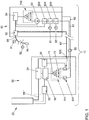
- a traction battery charging arrangement 10 for charging a traction battery of a motor vehicle is shown schematically.
- the charging arrangement 10 has a modular structure and essentially has an optional transformer unit 20, a supply unit 30 and a charging station 50.
- the optional transformer unit 20 converts the voltage of 10-20 kV coming from a medium-voltage network into a low voltage of less than 1000 V, which the The working voltage or the input voltage of the supply unit 30 is and is made available to the supply unit 30 via a supply line 55 ′′.
- the supply unit 30 has a charging current control means 34 with power electronics, by means of which the low voltage fed in is converted into the charging voltage with which the traction battery of the connected motor vehicle is to be charged. Since the power electronics generate a lot of heat with charging powers of several 100 kW, the supply unit 30 has a cooling device 38 which has a heat exchanger and a compressor and which is used essentially to cool the power electronics of the charging current control means 34.
- the supply unit 30 has a supply unit controller 36 which controls, synchronizes and monitors all components of the supply unit 30, and also takes over the communication between the supply unit 30 and the other components of the charging arrangement 10.
- the supply unit 30 has an optional interface module 32, via which the supply unit controller 36 can communicate with the transformer unit 20.
- the charging station 50 has a charging station controller 54, a charging cable 55 with a charging plug 56 and a charging current control means 52 for switching the charging voltage through to the charging plug 56.
- the charging voltage generated in the charging current control means 34 is fed into the charging station 50 through a charging current line 55 ′.
- the charging station 50 is set up away from the supply unit 30, for example more than 10 m away from the supply unit 30.
- the charging station 50 has no noteworthy power electronics, and therefore has no or only a small heat exchanger cooling device for the charging cable to the cooling unit, see above that the noise emissions of the charging station 50 are relatively low.
- a single charging station 50 is assigned to the supply unit 30.
- a single supply unit 30 however, several individual and remotely arranged charging stations 50 can also be assigned.
- the charging arrangement 10 has an electrical safety loop 60 which can have a multiplicity of components which are provided both in the supply unit 30 and in the charging station 50.
- the safety loop 60 essentially consists of two loop lines 61, 62 between the supply unit 30 and the charging station 50, a loop current source 53 in the charging station 50, several loop openers 601-605 in the charging station 50 and the supply unit 30 and one each Loop current sensor 701, 702 in the charging station 50 and the supply unit 30. All of the aforementioned components are electrically connected in series and form a closed circuit.
- the supply unit 30 has two loop openers 601, 602 which are actuated or controlled by the cooling device 38 and by the supply unit controller 36. As soon as the cooling device 38 or the supply unit control 36 detects a fault, the associated loop opener 601, 602 is activated so that the safety loop 60 is opened electrically.
- the loop current sensor 701, 702 is essentially formed by a measuring resistor 72 and an operational amplifier 71, and outputs a proportional voltage signal that drops across the measuring resistor 72 to the connected supply unit controller 36.
- the charging station 50 has three loop openers 603, 604, 605. Two of these loop openers 604, 605 are each actuated or switched by a temperature sensor 81, 82.
- the two temperature sensors 81, 82 are arranged in the charging cable 55 and monitor the temperature in the charging cable 55. As soon as one of the temperature sensors 81, 82 determines that a limit temperature has been exceeded this signals the assigned loop opener 604, 605, which then opens.
- the loop current sensor 702 of the charging station 50 is constructed identically to the loop current sensor 701 of the supply unit 30 and transmits the voltage signal dropping across the relevant measuring resistor to the charging station controller 54 controlled by yourself.
- the loop current source 53 is activated.
- the loop current source 53 generates a positive alternating signal in the present case, which in the Figure 2 is shown as an example.
- the alternating signal is a square-wave signal that alternates between 15 mA and 25 mA with a frequency in the low single-digit Hertz range.
- the loop current source 53 generates an alternating signal 92 with a frequency of 8 Hz, for example, or an alternating signal 94 with a frequency of 5 Hz Hz, 3 Hz and 8 Hz.
- the two loop current sensors 701, 702 signal the assigned charging current control means 34, 52 a zero signal and thus the non-readiness, so that no charging current flows. Only when all the loop openers 601-605 are closed are the two charging current control means 34, 52 closed so that the charging current can flow through the charging current line 55 ′ and the charging cable 55 to the charging plug 56.
- the frequency of the alternating signal 92, 94 in the safety loop 60 clearly signals to the supply unit controller 36 which charging voltage is required. If there is no correspondence with the information about the charging standard or charging voltage supplied via another information channel, the supply unit controller 36 can immediately use the associated loop opener 601 to open. In the event that the charging station controller 54 detects inconsistencies or faults, the charging station controller 54 opens the associated loop opener 603.
- the controls 36, 54 take measures to protect the charging arrangement 10 from damage.
Landscapes
- Engineering & Computer Science (AREA)
- Power Engineering (AREA)
- Transportation (AREA)
- Mechanical Engineering (AREA)
- Life Sciences & Earth Sciences (AREA)
- Sustainable Development (AREA)
- Sustainable Energy (AREA)
- Microelectronics & Electronic Packaging (AREA)
- Charge And Discharge Circuits For Batteries Or The Like (AREA)
- Electric Propulsion And Braking For Vehicles (AREA)
- Secondary Cells (AREA)
Description
- Die Erfindung bezieht sich auf eine Traktionsbatterie-Ladeanordnung zum Aufladen einer Traktionsbatterie eines Kraftfahrzeugs.
- Eine Ladeanordnung zum Aufladen einer Traktionsbatterie eines Kraftfahrzeugs besteht aus mehreren Komponenten, insbesondere aus der eigentlichen Ladestation, die einen Ladestecker zur Herstellung einer elektrischen Ladeverbindung mit der Traktionsbatterie des Kraftfahrzeugs aufweist, und der elektrischen Aufbereitung, der aus dem Stromnetz zur Verfügung gestellten Mittelspannung, um hieraus die erforderliche Ladespannung zu generieren. In sogenannten Ladeparks werden von einer Aufbereitungseinheit gegebenenfalls eine Vielzahl von Ladestationen elektrisch versorgt. Die Kommunikation zwischen den Komponenten einer Ladeanordnung bzw. eines Ladeparks erfolgt über digitale Kommunikationsleitungen, die jedoch grundsätzlich nicht unempfindlich sind im Bezug auf Störungen, Verzögerungen etc., insbesondere dann, wenn die Ladeanordnungs-Komponenten räumlich weiter auseinanderliegen. Wegen der hohen elektrischen Ströme, die in einer Ladeanordnung in den Ladeleitungen fließen, besteht generell ein relativ hohes Risiko von Überhitzung bzw. Feuer. Es ist daher sicherzustellen, dass bei einer Störung an irgendeiner Komponente der gesamten Ladeanordnung eine sofortige Abschaltung aller Komponenten der Ladeanordnung erfolgt.
- Aus
DE 10 2015 116 105 A1 undUS 2016/0303986 A1 sind jeweils Ladeanordnungen zum Aufladen einer Traktionsbatterie eines Kraftfahrzeuges bekannt, die eine elektrische Sicherheitsschleife aufweisen. - Aufgabe der Erfindung ist es, eine mehrteilige Traktionsbatterie-Ladeanordnung mit einer zuverlässigen Sofortabschaltung zur Verfügung zu stellen.
- Diese Aufgabe wird erfindungsgemäß gelöst durch eine Traktionsbatterie-Ladeanordnung mit den Merkmalen des Anspruchs 1.
- Die erfindungsgemäße Traktionsbatterie-Ladeanordnung weist eine Ladestation auf, die einen Ladestecker/ -buchse zur Herstellung einer elektrischen Ladeverbindung mit der Traktionsbatterie des Kraftfahrzeugs aufweist. Das Kraftfahrzeug weist einen zu dem Ladestations-Ladestecker korrespondierenden komplementären Ladestecker auf, der zum Aufladen der Kraftfahrzeug-Traktionsbatterie mit dem Ladestations-Ladestecker zusammengesteckt wird, so dass auf diese Weise eine elektrische Ladeverbindung hergestellt wird.
- Die Ladeanordnung weist eine elektrische Aufbereitung und Versorgung auf, die die Ladestation mit dem Ladestrom versorgt, und weist ein Ladestrom-Steuerungsmittel auf, das den Ladestrom bei Bedarf abschaltet.
- Die Ladeanordnung weist ferner eine elektrische Sicherheitsschleife auf, die eine Schleifenstrom-Quelle, mindestens einen ansteuerbaren Schleifenöffner und mindestens einen Schleifenstrom-Sensor aufweist. Die Sicherheitsschleife weist also einen geschlossenen Stromkreis mit einer Schleifenstrom-Quelle auf. Die Schleifenstrom-Quelle liefert einen Schleifenstrom mit einem definierten zeitlichen Schleifenstrom-Verlauf in der Schleifenleitung, beispielsweise einen konstanten oder nicht-konstanten Schleifenstrom von beispielsweise 25 mA und/oder 15mA.
- Der Schleifenöffner wird von einem zugeordneten, elektrischen, elektronischen oder mechanischen Stellelement ausgelöst und geöffnet, sobald das betreffende Stellelement eine definierte Störung feststellt. Das Stellelement kann beispielsweise ein Temperatursensor sein, der die Überschreitung einer Grenztemperatur feststellt, und der im Falle einer Grenztemperatur-Überschreitung den betreffenden Schleifenöffner öffnet. Das Stellelement kann auch ein elektronisches Modul, ein Kippsensor, Türöffnungs-Kontakt, Wasserstandsensor etc. sein. Besonders bevorzugt sind im Verlauf der Schleifenleitung mehrere Schleifenöffner vorgesehen, die elektrisch seriell in der Sicherheitsschleife bzw. in der Schleifenleitung angeordnet sind und denen ggf. Stellelemente zugeordnet sind.
- Es ist eine separat von der Ladestation ausgebildete Versorgungseinheit vorgesehen, die über eine elektrische Ladestrom-Leitung mit der Ladestation verbunden ist. Die Sicherheitsschleife durchläuft sowohl die Versorgungseinheit als auch die Ladestation. Sowohl die Versorgungseinheit als auch die Ladestation weisen jeweils mindestens einen Schleifenstrom-Sensor und jeweils ein dem Schleifenstrom-Sensor jeweils zugeordnetes Ladestrom-Steuerungsmittel auf.
- Der Schleifenstrom-Sensor detektiert kontinuierlich den in der elektrischen Sicherheitsschleife bzw. in der Schleifenleitung fließenden Strom, beispielsweise durch einen Spannungsabgriff an einem in der Schleifenleitung in Serie geschalteten Messwiderstand. Der Schleifenstrom-Sensor ist informell bzw. elektrisch mit dem Ladestrom-Steuerungsmittel verbunden. Sobald der Schleifenstrom-Sensor keinen Schleifenstrom in der Sollflussstärke detektiert, wird der Ladestrom durch das Ladestrom-Steuerungsmittel abgeschaltet, so dass die mit einer Nichtabschaltung verbundenen Gefahren vermieden werden.
- Die Schleifenstrom-Quelle ist bevorzugt einer Anlagensteuerung informell bzw. elektrisch zugeordnet, die die Schleifenstrom-Quelle einschaltet, bevor die Anlagensteuerung aufgrund der ihr vorliegenden Informationen das Aufschalten des Ladestroms erlaubt.
- Vorzugsweise ist die Sicherheitsschleife bzw. sind die Schleifenleitungen galvanisch getrennt von der übrigen Elektrik und Elektronik der Ladeanordnung, um auf diese Weise Erdschleifen auszuschließen.
- Die Ladestation kann entfernt von der Versorgungseinheit angeordnet und platziert sein, so dass die Geräuschemissionen der Versorgungseinheit lokal dorthin verlagert werden können, wo sie weniger stören. Die Ladestation kann beispielsweise bis zu 100 m oder sogar noch weiter entfernt von der Versorgungseinheit aufgestellt sein. An eine Versorgungseinheit können mehrere Ladestationen angeschlossen sein.
- Vorzugsweise ist das Ladestrom-Steuerungsmittel der Versorgungseinheit als Leistungselektronik ausgebildet, die den Ladestrom in der erforderlichen Ladespannung generiert. Die Ladestation weist vorzugsweise keine mit einem Wärmetauscher-Kühlaggregat zu kühlende Leistungselektronik auf, so dass die Ladestation sehr kompakt ausgebildet sein kann. Durch den Wegfall einer relativ lauten Kühlung entfallen auch die damit verbundenen Geräuschemissionen an der Ladestation. Die Ladestation unterliegt daher nur geringen gesetzlichen Restriktionen und hat eine hohe Komfortqualität.
- Gemäß einer bevorzugten Ausgestaltung weist sowohl die Ladestation als auch die Versorgungseinheit jeweils mindestens einen Schleifenöffner auf. Auf diese Weise können auch bei relativ großer Entfernung zwischen der Ladestation und der Versorgungseinheit Störungen an irgendeinem Ort der Ladeanordnung schnell zu einer Abschaltung der Ladespannung führen.
- Gemäß einer bevorzugten Ausgestaltung ist die Schleifenstrom-Quelle derart ausgebildet, dass sie ein positives Wechselsignal generiert. Hierunter wird beispielsweise ein niederfrequentes Wechselsignal verstanden, das seine Polarität nicht ändert, jedoch beispielsweise zwischen zwei Stromflussplateaus alternierend wechselt, beispielsweise mit einer Frequenz im einstelligen Hertzbereich. Beispielsweise kann das Wechselsignal ein Rechtecksignal sein, das zwischen 25 mA und 15 mA mit einer Frequenz von 5 Hz wechselt. Das Wechselsignal wird von dem Schleifenstrom-Sensor ausgewertet. Wenn kein Wechselsignal vorliegt, sondern ein positives Gleichsignal, ist die Schleifenstrom-Quelle möglicherweise defekt, so dass auch dies identifiziert werden und mit geeigneten Maßnahmen hierauf reagiert werden kann.
- Vorzugsweise ist die Schleifenstrom-Quelle derart ausgebildet, dass sie das Wechselsignal wahlweise mit mindestens zwei verschiedenen Wechselfrequenzen generieren kann. Auf diese Weise kann die Schleifenstrom-Quelle eine einfache Information an die Schleifenstrom-Sensoren übermitteln. So kann über die Wechselfrequenz beispielsweise die gewählte Ladenorm bzw. Ladespannung übermittelt werden.
- Vorzugweise ist die Schleifenstrom-Quelle in der Ladestation angeordnet. In der Ladestation wird die Ladenorm bzw. die Ladespannung gewählt bzw. festgelegt. Sobald dies erfolgt ist, ist die Ladestation grundsätzlich bereit zum Laden, so dass die Schleifenstrom-Quelle eingeschaltet wird und über die Wechselfrequenz in der Sicherheitsschleife die Ladenorm bzw. die Ladespannung an die Versorgungseinheit übermittelt. Hierdurch wird eine zusätzliche Sicherheit bzw. Redundanz bezüglich der Ladenorm bzw. Ladespannung hergestellt.
- Im Folgenden wird ein Ausführungsbeispiel anhand der Figuren näher erläutert, die zeigen:
-
Figur 1 eine schematische Darstellung einer Traktionsbatterie-Ladeanordnung mit einer elektrischen Sicherheitsschleife, und -
Figur 2 einen zeitlichen Verlauf eines Schleifenstroms in der Sicherheitsschleife der Ladeanordnung derFigur 1 . - In der
Figur 1 ist schematisch eine Traktionsbatterie-Ladeanordnung 10 zum Aufladen einer Traktionsbatterie eines Kraftfahrzeugs dargestellt. Die Ladeanordnung 10 ist im vorliegenden Fall modular aufgebaut, und weist im Wesentlichen eine optionale Umspanneinheit 20, eine Versorgungseinheit 30 und eine Ladestation 50 auf. - Die optionale Umspanneinheit 20 spannt die aus einem Mittelspannungsnetz kommende Spannung von 10-20 kV um in eine Niederspannung von unter 1000 V, die die Arbeitsspannung bzw. die Eingangsspannung der Versorgungseinheit 30 ist und der Versorgungseinheit 30 über eine Versorgungsleitung 55" zur Verfügung gestellt wird.
- Die Versorgungseinheit 30 weist ein Ladestrom-Steuerungsmittel 34 mit einer Leistungselektronik auf, durch das die eingespeiste Niederspannung umgewandelt wird in die Ladespannung, mit der die Traktionsbatterie des angeschlossenen Kraftfahrzeugs geladen werden soll. Da die Leistungselektronik bei Ladeleistungen von mehreren 100 kW viel Wärme erzeugt, weist die Versorgungseinheit 30 eine Kühlvorrichtung 38 auf, die einen Wärmetauscher und einen Kompressor aufweist, und die im Wesentlichen der Kühlung der Leistungselektronik des Ladestrom-Steuerungsmittels 34 dient.
- Schließlich weist die Versorgungseinheit 30 eine Versorgungseinheits-Steuerung 36 auf, die alle Bestandteile der Versorgungseinheit 30 steuert, synchronisiert und kontrolliert, sowie die Kommunikation der Versorgungseinheit 30 mit den übrigen Komponenten der Ladeanordnung 10 übernimmt. Die Versorgungseinheit 30 weist hierzu ein optionales Schnittstellenmodul 32 auf, über das die Versorgungseinheits-Steuerung 36 mit der Umspanneinheit 20 kommunizieren kann.
- Die Ladestation 50 weist eine Ladestations-Steuerung 54, ein Ladekabel 55 mit einem Ladestecker 56 und ein Ladestrom-Steuerungsmittel 52 zum Durchschalten der Ladespannung auf den Ladestecker 56 auf. Die in dem Ladestrom-Steuerungsmittel 34 generierte Ladespannung wird durch eine Ladestrom-Leitung 55' in die Ladestation 50 eingespeist. Die Ladestation 50 ist entfernt von der Versorgungseinheit 30 aufgestellt, beispielsweise mehr als 10 m entfernt von der Versorgungseinheit 30. Die Ladestation 50 weist keine nennenswerte Leistungselektronik auf, und weist daher keine oder nur eine kleine Wärmetauscher-Kühlvorrichtung für das Ladekabel zur Kühleinheit auf, so dass die Geräuschemissionen der Ladestation 50 relativ gering sind.
- Im dem vorliegenden Ausführungsbeispiel ist der Versorgungseinheit 30 nur eine einzige Ladestation 50 zugeordnet. Grundsätzlich können einer einzigen Versorgungseinheit 30 jedoch auch mehrere einzelne und entfernt angeordnete Ladestationen 50 zugeordnet sein.
- Die Ladeanordnung 10 weist eine elektrische Sicherheitsschleife 60 auf, die eine Vielzahl von Komponenten aufweisen kann, die sowohl in der Versorgungseinheit 30 als auch in der Ladestation 50 vorgesehen sind. Die Sicherheitsschleife 60 besteht aus elektrischer Sicht im Wesentlichen aus zwei Schleifenleitungen 61, 62 zwischen der Versorgungseinheit 30 und der Ladestation 50, einer Schleifenstrom-Quelle 53 in der Ladestation 50, mehreren Schleifenöffnern 601-605 in der Ladestation 50 und der Versorgungseinheit 30 und jeweils einem Schleifenstrom-Sensor 701, 702 in der Ladestation 50 und der Versorgungseinheit 30. Alle vorgenannten Komponenten sind elektrisch in Reihe geschaltet und bilden einen geschlossenen Stromkreis.
- Die Versorgungseinheit 30 weist in dem vorliegenden Ausführungsbeispiel zwei Schleifenöffner 601, 602 auf, die von der Kühlvorrichtung 38 und von der Versorgungseinheits-Steuerung 36 aktuiert bzw. angesteuert werden. Sobald die Kühlvorrichtung 38 oder die Versorgungseinheits-Steuerung 36 eine Störung detektiert, wird der zugeordnete Schleifenöffner 601, 602 aktiviert, so dass die Sicherheitsschleife 60 elektrisch geöffnet ist.
- Der Schleifenstrom-Sensor 701, 702 wird in diesem Ausführungsbeispiel im Wesentlichen von einem Messwiderstand 72 und einem Operationsverstärker 71 gebildet, und gibt ein an dem Messwiderstand 72 abfallendes proportionales Spannungssignal an die angeschlossene Versorgungseinheit-Steuerung 36 aus.
- Die Ladestation 50 weist drei Schleifenöffner 603, 604, 605 auf. Zwei dieser Schleifenöffner 604, 605 werden von jeweils einem Temperatursensor 81,82 aktuiert bzw. geschaltet. Die beiden Temperatursensoren 81, 82 sind in dem Ladekabel 55 angeordnet und überwachen die Temperatur in dem Ladekabel 55. Sobald einer der Temperatursensoren 81, 82 die Überschreitung einer Grenztemperatur feststellt, wird dies dem zugeordneten Schleifenöffner 604, 605 signalisiert, der daraufhin öffnet. Der Schleifenstrom-Sensor 702 der Ladestation 50 ist identisch zu dem Schleifenstrom-Sensor 701 der Versorgungseinheit 30 aufgebaut und übermittelt das an dem betreffenden Messwiderstand abfallende Spannungssignal an die Ladestations-Steuerung 54. Der dritte Schleifenöffner 603 der Ladestation 50 wird von der Ladestation-Steuerung 54 selbst angesteuert.
- Sobald an der Ladestation 50 die gewünschte Ladenorm bzw. Ladespannung gewählt und bevor die Ladeprozedur gestartet ist, wird die Schleifenstrom-Quelle 53 aktiviert. Die Schleifenstrom-Quelle 53 generiert im vorliegenden Fall ein positives Wechselsignal, das in der
Figur 2 exemplarisch dargestellt ist. Das Wechselsignal ist vorliegend ein Rechtecksignal, das zwischen 15 mA und 25 mA mit einer Frequenz im niedrigen einstelligen Hertzbereich alterniert. Je nach gewählter Ladenorm bzw. Ladespannung generiert die Schleifenstrom-Quelle 53 ein Wechselsignal 92 mit einer Frequenz von beispielsweise 8 Hz oder ein Wechselsignal 94 mit einer Frequenz von 5 Hz. Bei drei verschiedenen bedienbaren Ladenormen bzw. Ladespannungen können die hierfür erforderlichen drei Frequenzen beispielsweise 1 Hz, 3 Hz und 8 Hz betragen. - Solange nicht alle Schleifenöffner 601 - 605 geschlossen sind, signalisieren die beiden Schleifenstrom-Sensoren 701, 702 den zugeordneten Ladestrom-Steuerungsmitteln 34,52 ein Nullsignal und damit die Nicht-Bereitschaft, so dass kein Ladestrom fließt. Erst wenn alle Schleifenöffner 601-605 geschlossen sind, werden die beiden Ladestrom-Steuerungsmittel 34, 52 geschlossen, so dass der Ladestrom durch die Ladestromleitung 55' und das Ladekabel 55 zu dem Ladestecker 56 fließen kann.
- Über die Frequenz des Wechselsignals 92, 94 in der Sicherheitsschleife 60 wird der Versorgungseinheits-Steuerung 36 eindeutig signalisiert, welche Ladespannung gefordert ist. Falls sich hierbei keine Übereinstimmung ergibt mit den über einen anderen Informationskanal gelieferten Informationen über die Ladenorm bzw. die Ladespannung, kann die Versorgungseinheit-Steuerung 36 sofort den zugeordneten Schleifenöffner 601 öffnen. Für den Fall, dass die Ladestations-Steuerung 54 Inkonsistenzen oder Störungen detektiert, öffnet die Ladestations-Steuerung 54 den zugeordneten Schleifenöffner 603.
- Sobald einer der Schleifenstrom-Sensoren 701, 702 kein Wechselsignal 92, 94 oder aber nicht das erwartete Wechselsignal 92, 94 detektiert, werden durch die Steuerungen 36, 54 Maßnahmen ergriffen, um die Ladeanordnung 10 vor einer Beschädigung zu schützen.
Claims (8)
- Traktionsbatterie-Ladeanordnung (10) zum Aufladen einer Traktionsbatterie eines Kraftfahrzeugs, miteiner Ladestation (50), die einen Ladestecker (56) zur Herstellung einer elektrischen Ladeverbindung mit der Traktionsbatterie des Kraftfahrzeugs aufweist, einer separat von der Ladestation (50) ausgebildeten Versorgungseinheit (30), die über eine elektrische Ladestrom-Leitung (55') mit der Ladestation (50) verbunden ist,einer elektrischen Sicherheitsschleife (60), die eine Schleifenstrom-Quelle (53), mindestens einen ansteuerbaren Schleifenöffner (601-605) und mindestens einen Schleifenstrom-Sensor (701, 702) aufweist, undeinem Ladestrom-Steuerungsmittel (34,52), das den Ladestrom abschaltet, wenn der Schleifenstrom-Sensor (701, 702) keinen Schleifenstrom detektiert,gekennzeichnet dadurch, dass die Sicherheitsschleife (60) sowohl die Versorgungseinheit (30) als auch die Ladestation (50) durchläuft, und wobei die Versorgungseinheit (30) und die Ladestation (50) jeweils mindestens einen Schleifenstrom-Sensor (701, 702) und ein diesem jeweils zugeordnetes Ladestrom-Steuerungsmittel (34, 52) aufweisen.
- Traktionsbatterie-Ladeanordnung (10) nach Anspruch 1, wobei das Ladestrom-Steuerungsmittel (34) der Versorgungseinheit (30) als Leistungselektronik ausgebildet ist, die den Ladestrom in der erforderlichen Ladespannung generiert.
- Traktionsbatterie-Ladeanordnung (10) nach einem der vorangegangenen Ansprüche, wobei sowohl die Ladestation (50) als auch die Versorgungseinheit (30) jeweils mindestens einen Schleifenöffner (601-605) aufweist.
- Traktionsbatterie-Ladeanordnung (10) nach einem der vorangegangenen Ansprüche, wobei die Schleifenstrom-Quelle (53) derart ausgebildet ist, dass sie ein positives Wechselsignal (92, 94) generiert.
- Traktionsbatterie-Ladeanordnung (10) nach Anspruch 4, wobei die Schleifenstrom-Quelle (53) das Wechselsignal (92, 94) wahlweise mit mindestens zwei verschiedenen Wechselfrequenzen generieren kann.
- Traktionsbatterie-Ladeanordnung (10) nach einem der vorangegangenen Ansprüche, wobei die Schleifenstrom-Quelle (53) in der Ladestation (50) angeordnet ist.
- Traktionsbatterie-Ladeanordnung (10) nach einem der vorangegangenen Ansprüche, wobei der Schleifenöffner (604, 605) einem Temperatursensor (81, 82) derart funktional zugeordnet ist, dass der Schleifenöffner (604, 605) öffnet, sobald der Temperatursensor (81, 82) die Überschreitung einer Grenztemperatur signalisiert.
- Traktionsbatterie-Ladeanordnung (10) nach einem der vorangegangenen Ansprüche, wobei die Sicherheitsschleife (60) mehrere Schleifenöffner (601-605) aufweist, die elektrisch seriell in der Sicherheitsschleife (60) angeordnet sind.
Applications Claiming Priority (1)
| Application Number | Priority Date | Filing Date | Title |
|---|---|---|---|
| DE102018101510.0A DE102018101510B4 (de) | 2018-01-24 | 2018-01-24 | Traktionsbatterie-Ladeanordnung |
Publications (2)
| Publication Number | Publication Date |
|---|---|
| EP3517341A1 EP3517341A1 (de) | 2019-07-31 |
| EP3517341B1 true EP3517341B1 (de) | 2021-12-08 |
Family
ID=63965032
Family Applications (1)
| Application Number | Title | Priority Date | Filing Date |
|---|---|---|---|
| EP18020514.8A Active EP3517341B1 (de) | 2018-01-24 | 2018-10-18 | Traktionsbatterie-ladeanordnung |
Country Status (6)
| Country | Link |
|---|---|
| US (1) | US10926653B2 (de) |
| EP (1) | EP3517341B1 (de) |
| JP (1) | JP6823090B2 (de) |
| CN (1) | CN110065403A (de) |
| BR (1) | BR102019001211A2 (de) |
| DE (1) | DE102018101510B4 (de) |
Families Citing this family (3)
| Publication number | Priority date | Publication date | Assignee | Title |
|---|---|---|---|---|
| JP7369998B2 (ja) * | 2019-09-02 | 2023-10-27 | パナソニックIpマネジメント株式会社 | ケーブル支持器 |
| BE1028464B1 (de) * | 2020-07-09 | 2022-02-08 | Phoenix Contact Gmbh & Co | Technik zur Überwachung eines Kontakts zwischen Ladeleitern zum Laden eines Elektrofahrzeugs |
| CN116533803A (zh) * | 2022-01-25 | 2023-08-04 | 徐州坤达电动车有限公司 | 一种具有防自燃功能的电动车安全充电装置 |
Family Cites Families (26)
| Publication number | Priority date | Publication date | Assignee | Title |
|---|---|---|---|---|
| JPH08205376A (ja) | 1995-01-30 | 1996-08-09 | Nippon Signal Co Ltd:The | 高電圧発生装置及び高電圧試験装置 |
| JPH11299073A (ja) | 1998-04-16 | 1999-10-29 | Ando Electric Co Ltd | 非常停止回路 |
| US20040017643A1 (en) * | 2002-07-26 | 2004-01-29 | Ncr Corporation | Apparatus and method of controlling access to a service area of an equipment cabinet |
| JP2008113505A (ja) | 2006-10-30 | 2008-05-15 | Edison Power:Kk | バッテリーの温度管理システム |
| US20100268406A1 (en) | 2008-01-11 | 2010-10-21 | Toyota Jidosha Kabushiki Kaisha | Charging control apparatus for vehicle and vehicle |
| EP2166365A1 (de) * | 2008-09-19 | 2010-03-24 | Bombardier Transportation GmbH | Verteiltes Sicherheitsüberwachungssystem mit einer Sicherheitsschleife und Verfahren zum Testen eines solchen Systems |
| CN102576042B (zh) * | 2009-07-27 | 2015-11-25 | Rwe股份公司 | 用以对消费者提供供应装置中若干能量的装置及方法 |
| JP2011063431A (ja) * | 2009-09-18 | 2011-03-31 | Toshiba Elevator Co Ltd | エレベータの安全回路 |
| JPWO2011118187A1 (ja) * | 2010-03-23 | 2013-07-04 | パナソニック株式会社 | 充電制御装置、充電システムおよび充電制御方法 |
| US9368959B2 (en) * | 2011-09-06 | 2016-06-14 | Robert W. Wright, JR. | Displacement safety system for electrical charging stations |
| DE102012204862A1 (de) | 2012-03-27 | 2013-10-02 | Robert Bosch Gmbh | Sicherungseinrichtung für ein Hochvoltsystem und Verfahren zum Sichern eines Hochvoltsystems |
| KR20140003082A (ko) * | 2012-06-29 | 2014-01-09 | 엘에스산전 주식회사 | 전기 자동차용 충전기 |
| DE102012013405A1 (de) * | 2012-07-05 | 2014-01-09 | Audi Ag | Diagnoseeinrichtung zur Überprüfung einer Steuersignalleitung |
| JP6054200B2 (ja) * | 2013-02-22 | 2016-12-27 | 三菱重工業株式会社 | 充電システム |
| JP5780269B2 (ja) * | 2013-07-12 | 2015-09-16 | トヨタ自動車株式会社 | 電力供給システムおよび受電設備 |
| JP2015033144A (ja) | 2013-07-31 | 2015-02-16 | シンフォニアテクノロジー株式会社 | 移動体用充電装置 |
| CN103475051A (zh) * | 2013-09-02 | 2013-12-25 | 四川川奇机电有限责任公司 | 充电电路和具有该充电电路的充电器以及充电方法 |
| KR102199469B1 (ko) * | 2013-12-09 | 2021-01-06 | 한화디펜스 주식회사 | 전기차량에서 외부 차량과 상호 전력 공급을 수행하는 방법 및 장치 |
| DE102014111831A1 (de) * | 2014-08-19 | 2016-02-25 | Phoenix Contact E-Mobility Gmbh | Steckverbinderteil mit Temperatursensoren |
| US10081261B2 (en) * | 2014-10-01 | 2018-09-25 | Ford Global Technologies, Llc | High-voltage battery off-board chargers |
| DE102014016825B4 (de) * | 2014-11-13 | 2023-06-29 | Audi Ag | Kraftfahrzeug-Ladedose mit Überhitzungsschutz |
| CN204586541U (zh) * | 2015-03-30 | 2015-08-26 | 观致汽车有限公司 | 一种用于车辆的高压电路的监控系统 |
| CN105375569A (zh) * | 2015-11-19 | 2016-03-02 | 内蒙古电力勘测设计院有限责任公司 | 总线型电动汽车交流充电桩及其容量扩充方法 |
| DE102015122217A1 (de) * | 2015-12-18 | 2017-06-22 | Rwe Ag | Sicherheitsmodul und Ladestation mit Sicherheitsmodul |
| CN206135460U (zh) * | 2016-05-25 | 2017-04-26 | 江门市甜的电器有限公司 | 一种充电桩过热保护电路 |
| JP6586396B2 (ja) * | 2016-06-17 | 2019-10-02 | 株式会社オートネットワーク技術研究所 | 通信装置、充電通信システム、輸送機器及び故障診断方法 |
-
2018
- 2018-01-24 DE DE102018101510.0A patent/DE102018101510B4/de active Active
- 2018-10-18 EP EP18020514.8A patent/EP3517341B1/de active Active
-
2019
- 2019-01-22 CN CN201910058290.8A patent/CN110065403A/zh active Pending
- 2019-01-22 US US16/253,611 patent/US10926653B2/en active Active
- 2019-01-22 BR BR102019001211-0A patent/BR102019001211A2/pt not_active Application Discontinuation
- 2019-01-23 JP JP2019009263A patent/JP6823090B2/ja active Active
Also Published As
| Publication number | Publication date |
|---|---|
| JP2019129702A (ja) | 2019-08-01 |
| DE102018101510B4 (de) | 2024-12-05 |
| BR102019001211A2 (pt) | 2019-08-06 |
| CN110065403A (zh) | 2019-07-30 |
| DE102018101510A1 (de) | 2019-07-25 |
| US20190225102A1 (en) | 2019-07-25 |
| US10926653B2 (en) | 2021-02-23 |
| JP6823090B2 (ja) | 2021-01-27 |
| EP3517341A1 (de) | 2019-07-31 |
Similar Documents
| Publication | Publication Date | Title |
|---|---|---|
| EP3517341B1 (de) | Traktionsbatterie-ladeanordnung | |
| DE102010017747A1 (de) | Verfahren zur Begrenzung der Generatorspannung einer photovoltaischen Anlage im Gefahrenfall und photovoltaische Anlage | |
| DE69404218T2 (de) | Impedanzverbindung für Schienenwege | |
| EP3781430A1 (de) | Batteriemanagementsystem mit schaltersteuerung, insbesondere für ein schienenfahrzeug | |
| EP1728305A1 (de) | Vorrichtung zur ladeverteilung und berwachung von mehreren akkumulatoren | |
| EP3042805B1 (de) | Vorrichtung zum überwachen eines bordnetzes | |
| DE102010047227B3 (de) | Gefahrenmelder, Gefahrenmeldeanlage und Verfahren zum Erkennen von Leitungsfehlern | |
| DE2828645A1 (de) | Einrichtung zur steuerung von mindestens zwei hydraulischen turbinen | |
| EP2865072B1 (de) | Stellantrieb, stellantriebanlage, verfahren zum betreiben eines stellantriebs und verfahren zum betreiben einer stellantriebanlage | |
| DE102013109608B4 (de) | Verfahren zum und Einspeisesteuerung für das Einspeisen von elektrischer Leistung in einen Leitungszweig | |
| WO2021077143A1 (de) | Entladung oder ladung von batteriemodulen | |
| DE102010023145A1 (de) | Photovoltaikanlage, Sicherheitsvorrichtung für eine Photovoltaikanlage und Schutzeinheit für ein Photovoltaikmodul | |
| WO2001001541A1 (de) | Bussystem mit abgesicherten ausgängen | |
| DE19539070C2 (de) | Anordnung zum Ansteuern einer Auslösevorrichtung eines Rückhaltesystems | |
| DE102011050468A1 (de) | Photovoltaikanlage mit einer Schalteinrichtung zum elektrischen Trennen einzelner Photovoltaik-Module | |
| DE102011017681A1 (de) | Lichtsignaleinrichtung sowie Verfahren zur Steuerung einer Lichtsignaleinrichtung | |
| WO2018086768A1 (de) | Induktive ladestation und verfahren zum steuern einer induktiven ladestation | |
| EP1068700B1 (de) | Signalisierungsendstufe zur erzeugung digitaler spannungssignale auf einem bussystem | |
| EP0949735B1 (de) | Verfahren und Schaltungsanordnung zur Sicherheitsüberprüfung einer Hochspannungsversorgungsanlage | |
| EP1493218B1 (de) | Not-aus-system für induktiv versorgte verbraucher | |
| EP3723238A1 (de) | Elektrische anlage | |
| DE202025104057U1 (de) | System zur Steuerung und/oder zur Überwachung von Komponenten einer klimatechnischen Anlage, einer Brand-/Rauchschutz- und/oder einer Rauch- und Wärmeabzugsanlage eines Gebäudes | |
| DE3018327C2 (de) | Verfahren und Anordnung zur Prüfung der Steuer- und Regelfunktionen eines drehzahlgeregelten Antriebes | |
| DE102023135344A1 (de) | Elektrisches Gerät und Verfahren zum Betreiben eines elektrischen Geräts | |
| EP4014329A1 (de) | Anordnung zur informationsübertragung bei einer komponente eines fahrzeuges |
Legal Events
| Date | Code | Title | Description |
|---|---|---|---|
| PUAI | Public reference made under article 153(3) epc to a published international application that has entered the european phase |
Free format text: ORIGINAL CODE: 0009012 |
|
| STAA | Information on the status of an ep patent application or granted ep patent |
Free format text: STATUS: THE APPLICATION HAS BEEN PUBLISHED |
|
| AK | Designated contracting states |
Kind code of ref document: A1 Designated state(s): AL AT BE BG CH CY CZ DE DK EE ES FI FR GB GR HR HU IE IS IT LI LT LU LV MC MK MT NL NO PL PT RO RS SE SI SK SM TR |
|
| AX | Request for extension of the european patent |
Extension state: BA ME |
|
| STAA | Information on the status of an ep patent application or granted ep patent |
Free format text: STATUS: REQUEST FOR EXAMINATION WAS MADE |
|
| 17P | Request for examination filed |
Effective date: 20200131 |
|
| RBV | Designated contracting states (corrected) |
Designated state(s): AL AT BE BG CH CY CZ DE DK EE ES FI FR GB GR HR HU IE IS IT LI LT LU LV MC MK MT NL NO PL PT RO RS SE SI SK SM TR |
|
| GRAP | Despatch of communication of intention to grant a patent |
Free format text: ORIGINAL CODE: EPIDOSNIGR1 |
|
| STAA | Information on the status of an ep patent application or granted ep patent |
Free format text: STATUS: GRANT OF PATENT IS INTENDED |
|
| INTG | Intention to grant announced |
Effective date: 20210628 |
|
| GRAS | Grant fee paid |
Free format text: ORIGINAL CODE: EPIDOSNIGR3 |
|
| GRAA | (expected) grant |
Free format text: ORIGINAL CODE: 0009210 |
|
| STAA | Information on the status of an ep patent application or granted ep patent |
Free format text: STATUS: THE PATENT HAS BEEN GRANTED |
|
| AK | Designated contracting states |
Kind code of ref document: B1 Designated state(s): AL AT BE BG CH CY CZ DE DK EE ES FI FR GB GR HR HU IE IS IT LI LT LU LV MC MK MT NL NO PL PT RO RS SE SI SK SM TR |
|
| REG | Reference to a national code |
Ref country code: GB Ref legal event code: FG4D Free format text: NOT ENGLISH |
|
| REG | Reference to a national code |
Ref country code: AT Ref legal event code: REF Ref document number: 1453514 Country of ref document: AT Kind code of ref document: T Effective date: 20211215 Ref country code: CH Ref legal event code: EP |
|
| REG | Reference to a national code |
Ref country code: DE Ref legal event code: R096 Ref document number: 502018008083 Country of ref document: DE |
|
| REG | Reference to a national code |
Ref country code: IE Ref legal event code: FG4D Free format text: LANGUAGE OF EP DOCUMENT: GERMAN |
|
| REG | Reference to a national code |
Ref country code: NO Ref legal event code: T2 Effective date: 20211208 |
|
| REG | Reference to a national code |
Ref country code: LT Ref legal event code: MG9D |
|
| REG | Reference to a national code |
Ref country code: NL Ref legal event code: MP Effective date: 20211208 |
|
| PG25 | Lapsed in a contracting state [announced via postgrant information from national office to epo] |
Ref country code: RS Free format text: LAPSE BECAUSE OF FAILURE TO SUBMIT A TRANSLATION OF THE DESCRIPTION OR TO PAY THE FEE WITHIN THE PRESCRIBED TIME-LIMIT Effective date: 20211208 Ref country code: LT Free format text: LAPSE BECAUSE OF FAILURE TO SUBMIT A TRANSLATION OF THE DESCRIPTION OR TO PAY THE FEE WITHIN THE PRESCRIBED TIME-LIMIT Effective date: 20211208 Ref country code: FI Free format text: LAPSE BECAUSE OF FAILURE TO SUBMIT A TRANSLATION OF THE DESCRIPTION OR TO PAY THE FEE WITHIN THE PRESCRIBED TIME-LIMIT Effective date: 20211208 Ref country code: BG Free format text: LAPSE BECAUSE OF FAILURE TO SUBMIT A TRANSLATION OF THE DESCRIPTION OR TO PAY THE FEE WITHIN THE PRESCRIBED TIME-LIMIT Effective date: 20220308 |
|
| PG25 | Lapsed in a contracting state [announced via postgrant information from national office to epo] |
Ref country code: SE Free format text: LAPSE BECAUSE OF FAILURE TO SUBMIT A TRANSLATION OF THE DESCRIPTION OR TO PAY THE FEE WITHIN THE PRESCRIBED TIME-LIMIT Effective date: 20211208 Ref country code: LV Free format text: LAPSE BECAUSE OF FAILURE TO SUBMIT A TRANSLATION OF THE DESCRIPTION OR TO PAY THE FEE WITHIN THE PRESCRIBED TIME-LIMIT Effective date: 20211208 Ref country code: HR Free format text: LAPSE BECAUSE OF FAILURE TO SUBMIT A TRANSLATION OF THE DESCRIPTION OR TO PAY THE FEE WITHIN THE PRESCRIBED TIME-LIMIT Effective date: 20211208 Ref country code: GR Free format text: LAPSE BECAUSE OF FAILURE TO SUBMIT A TRANSLATION OF THE DESCRIPTION OR TO PAY THE FEE WITHIN THE PRESCRIBED TIME-LIMIT Effective date: 20220309 Ref country code: ES Free format text: LAPSE BECAUSE OF FAILURE TO SUBMIT A TRANSLATION OF THE DESCRIPTION OR TO PAY THE FEE WITHIN THE PRESCRIBED TIME-LIMIT Effective date: 20211208 |
|
| PG25 | Lapsed in a contracting state [announced via postgrant information from national office to epo] |
Ref country code: NL Free format text: LAPSE BECAUSE OF FAILURE TO SUBMIT A TRANSLATION OF THE DESCRIPTION OR TO PAY THE FEE WITHIN THE PRESCRIBED TIME-LIMIT Effective date: 20211208 |
|
| PG25 | Lapsed in a contracting state [announced via postgrant information from national office to epo] |
Ref country code: SM Free format text: LAPSE BECAUSE OF FAILURE TO SUBMIT A TRANSLATION OF THE DESCRIPTION OR TO PAY THE FEE WITHIN THE PRESCRIBED TIME-LIMIT Effective date: 20211208 Ref country code: SK Free format text: LAPSE BECAUSE OF FAILURE TO SUBMIT A TRANSLATION OF THE DESCRIPTION OR TO PAY THE FEE WITHIN THE PRESCRIBED TIME-LIMIT Effective date: 20211208 Ref country code: RO Free format text: LAPSE BECAUSE OF FAILURE TO SUBMIT A TRANSLATION OF THE DESCRIPTION OR TO PAY THE FEE WITHIN THE PRESCRIBED TIME-LIMIT Effective date: 20211208 Ref country code: PT Free format text: LAPSE BECAUSE OF FAILURE TO SUBMIT A TRANSLATION OF THE DESCRIPTION OR TO PAY THE FEE WITHIN THE PRESCRIBED TIME-LIMIT Effective date: 20220408 Ref country code: EE Free format text: LAPSE BECAUSE OF FAILURE TO SUBMIT A TRANSLATION OF THE DESCRIPTION OR TO PAY THE FEE WITHIN THE PRESCRIBED TIME-LIMIT Effective date: 20211208 Ref country code: CZ Free format text: LAPSE BECAUSE OF FAILURE TO SUBMIT A TRANSLATION OF THE DESCRIPTION OR TO PAY THE FEE WITHIN THE PRESCRIBED TIME-LIMIT Effective date: 20211208 |
|
| PG25 | Lapsed in a contracting state [announced via postgrant information from national office to epo] |
Ref country code: PL Free format text: LAPSE BECAUSE OF FAILURE TO SUBMIT A TRANSLATION OF THE DESCRIPTION OR TO PAY THE FEE WITHIN THE PRESCRIBED TIME-LIMIT Effective date: 20211208 |
|
| REG | Reference to a national code |
Ref country code: DE Ref legal event code: R097 Ref document number: 502018008083 Country of ref document: DE |
|
| PG25 | Lapsed in a contracting state [announced via postgrant information from national office to epo] |
Ref country code: IS Free format text: LAPSE BECAUSE OF FAILURE TO SUBMIT A TRANSLATION OF THE DESCRIPTION OR TO PAY THE FEE WITHIN THE PRESCRIBED TIME-LIMIT Effective date: 20220408 |
|
| PLBE | No opposition filed within time limit |
Free format text: ORIGINAL CODE: 0009261 |
|
| STAA | Information on the status of an ep patent application or granted ep patent |
Free format text: STATUS: NO OPPOSITION FILED WITHIN TIME LIMIT |
|
| PG25 | Lapsed in a contracting state [announced via postgrant information from national office to epo] |
Ref country code: DK Free format text: LAPSE BECAUSE OF FAILURE TO SUBMIT A TRANSLATION OF THE DESCRIPTION OR TO PAY THE FEE WITHIN THE PRESCRIBED TIME-LIMIT Effective date: 20211208 Ref country code: AL Free format text: LAPSE BECAUSE OF FAILURE TO SUBMIT A TRANSLATION OF THE DESCRIPTION OR TO PAY THE FEE WITHIN THE PRESCRIBED TIME-LIMIT Effective date: 20211208 |
|
| 26N | No opposition filed |
Effective date: 20220909 |
|
| PG25 | Lapsed in a contracting state [announced via postgrant information from national office to epo] |
Ref country code: SI Free format text: LAPSE BECAUSE OF FAILURE TO SUBMIT A TRANSLATION OF THE DESCRIPTION OR TO PAY THE FEE WITHIN THE PRESCRIBED TIME-LIMIT Effective date: 20211208 |
|
| PG25 | Lapsed in a contracting state [announced via postgrant information from national office to epo] |
Ref country code: MC Free format text: LAPSE BECAUSE OF FAILURE TO SUBMIT A TRANSLATION OF THE DESCRIPTION OR TO PAY THE FEE WITHIN THE PRESCRIBED TIME-LIMIT Effective date: 20211208 Ref country code: IT Free format text: LAPSE BECAUSE OF FAILURE TO SUBMIT A TRANSLATION OF THE DESCRIPTION OR TO PAY THE FEE WITHIN THE PRESCRIBED TIME-LIMIT Effective date: 20211208 |
|
| REG | Reference to a national code |
Ref country code: CH Ref legal event code: PL |
|
| REG | Reference to a national code |
Ref country code: BE Ref legal event code: MM Effective date: 20221031 |
|
| PG25 | Lapsed in a contracting state [announced via postgrant information from national office to epo] |
Ref country code: LU Free format text: LAPSE BECAUSE OF NON-PAYMENT OF DUE FEES Effective date: 20221018 |
|
| P01 | Opt-out of the competence of the unified patent court (upc) registered |
Effective date: 20230526 |
|
| PG25 | Lapsed in a contracting state [announced via postgrant information from national office to epo] |
Ref country code: LI Free format text: LAPSE BECAUSE OF NON-PAYMENT OF DUE FEES Effective date: 20221031 Ref country code: CH Free format text: LAPSE BECAUSE OF NON-PAYMENT OF DUE FEES Effective date: 20221031 |
|
| PG25 | Lapsed in a contracting state [announced via postgrant information from national office to epo] |
Ref country code: BE Free format text: LAPSE BECAUSE OF NON-PAYMENT OF DUE FEES Effective date: 20221031 |
|
| PG25 | Lapsed in a contracting state [announced via postgrant information from national office to epo] |
Ref country code: IE Free format text: LAPSE BECAUSE OF NON-PAYMENT OF DUE FEES Effective date: 20221018 |
|
| PG25 | Lapsed in a contracting state [announced via postgrant information from national office to epo] |
Ref country code: HU Free format text: LAPSE BECAUSE OF FAILURE TO SUBMIT A TRANSLATION OF THE DESCRIPTION OR TO PAY THE FEE WITHIN THE PRESCRIBED TIME-LIMIT; INVALID AB INITIO Effective date: 20181018 |
|
| PG25 | Lapsed in a contracting state [announced via postgrant information from national office to epo] |
Ref country code: CY Free format text: LAPSE BECAUSE OF FAILURE TO SUBMIT A TRANSLATION OF THE DESCRIPTION OR TO PAY THE FEE WITHIN THE PRESCRIBED TIME-LIMIT Effective date: 20211208 |
|
| PG25 | Lapsed in a contracting state [announced via postgrant information from national office to epo] |
Ref country code: MK Free format text: LAPSE BECAUSE OF FAILURE TO SUBMIT A TRANSLATION OF THE DESCRIPTION OR TO PAY THE FEE WITHIN THE PRESCRIBED TIME-LIMIT Effective date: 20211208 |
|
| PG25 | Lapsed in a contracting state [announced via postgrant information from national office to epo] |
Ref country code: MT Free format text: LAPSE BECAUSE OF FAILURE TO SUBMIT A TRANSLATION OF THE DESCRIPTION OR TO PAY THE FEE WITHIN THE PRESCRIBED TIME-LIMIT Effective date: 20211208 |
|
| REG | Reference to a national code |
Ref country code: AT Ref legal event code: MM01 Ref document number: 1453514 Country of ref document: AT Kind code of ref document: T Effective date: 20231018 |
|
| PG25 | Lapsed in a contracting state [announced via postgrant information from national office to epo] |
Ref country code: AT Free format text: LAPSE BECAUSE OF NON-PAYMENT OF DUE FEES Effective date: 20231018 |
|
| PG25 | Lapsed in a contracting state [announced via postgrant information from national office to epo] |
Ref country code: AT Free format text: LAPSE BECAUSE OF NON-PAYMENT OF DUE FEES Effective date: 20231018 |
|
| PG25 | Lapsed in a contracting state [announced via postgrant information from national office to epo] |
Ref country code: TR Free format text: LAPSE BECAUSE OF FAILURE TO SUBMIT A TRANSLATION OF THE DESCRIPTION OR TO PAY THE FEE WITHIN THE PRESCRIBED TIME-LIMIT Effective date: 20211208 |
|
| PGFP | Annual fee paid to national office [announced via postgrant information from national office to epo] |
Ref country code: DE Payment date: 20251029 Year of fee payment: 8 |
|
| PGFP | Annual fee paid to national office [announced via postgrant information from national office to epo] |
Ref country code: GB Payment date: 20251022 Year of fee payment: 8 |
|
| PGFP | Annual fee paid to national office [announced via postgrant information from national office to epo] |
Ref country code: NO Payment date: 20251024 Year of fee payment: 8 |
|
| PGFP | Annual fee paid to national office [announced via postgrant information from national office to epo] |
Ref country code: FR Payment date: 20251030 Year of fee payment: 8 |
|
| PGFP | Annual fee paid to national office [announced via postgrant information from national office to epo] |
Ref country code: AT Payment date: 20260410 Year of fee payment: 5 |