EP3516280B1 - Coordinated water environment mobile robots - Google Patents
Coordinated water environment mobile robots Download PDFInfo
- Publication number
- EP3516280B1 EP3516280B1 EP17777445.2A EP17777445A EP3516280B1 EP 3516280 B1 EP3516280 B1 EP 3516280B1 EP 17777445 A EP17777445 A EP 17777445A EP 3516280 B1 EP3516280 B1 EP 3516280B1
- Authority
- EP
- European Patent Office
- Prior art keywords
- underwater
- robotic
- target structure
- tool
- protrusion
- Prior art date
- Legal status (The legal status is an assumption and is not a legal conclusion. Google has not performed a legal analysis and makes no representation as to the accuracy of the status listed.)
- Active
Links
- XLYOFNOQVPJJNP-UHFFFAOYSA-N water Substances O XLYOFNOQVPJJNP-UHFFFAOYSA-N 0.000 title description 13
- 238000003032 molecular docking Methods 0.000 claims description 74
- 230000007246 mechanism Effects 0.000 claims description 58
- 230000006641 stabilisation Effects 0.000 claims description 37
- 238000011105 stabilization Methods 0.000 claims description 37
- 238000000034 method Methods 0.000 claims description 22
- 238000004140 cleaning Methods 0.000 claims description 16
- 238000007689 inspection Methods 0.000 claims description 15
- 230000008859 change Effects 0.000 claims description 8
- 230000008878 coupling Effects 0.000 claims description 4
- 238000010168 coupling process Methods 0.000 claims description 4
- 238000005859 coupling reaction Methods 0.000 claims description 4
- 230000004907 flux Effects 0.000 description 9
- 238000004891 communication Methods 0.000 description 6
- 238000006243 chemical reaction Methods 0.000 description 4
- 230000033001 locomotion Effects 0.000 description 4
- 230000000295 complement effect Effects 0.000 description 3
- 238000010276 construction Methods 0.000 description 3
- 230000008439 repair process Effects 0.000 description 3
- 238000012360 testing method Methods 0.000 description 3
- 238000005516 engineering process Methods 0.000 description 2
- 238000012423 maintenance Methods 0.000 description 2
- 230000006978 adaptation Effects 0.000 description 1
- 238000004873 anchoring Methods 0.000 description 1
- 238000004590 computer program Methods 0.000 description 1
- 238000012937 correction Methods 0.000 description 1
- 238000005260 corrosion Methods 0.000 description 1
- 230000007797 corrosion Effects 0.000 description 1
- 230000001066 destructive effect Effects 0.000 description 1
- 238000006073 displacement reaction Methods 0.000 description 1
- 238000007667 floating Methods 0.000 description 1
- 238000012986 modification Methods 0.000 description 1
- 230000004048 modification Effects 0.000 description 1
- 238000009659 non-destructive testing Methods 0.000 description 1
- 230000000717 retained effect Effects 0.000 description 1
- 230000002441 reversible effect Effects 0.000 description 1
- 239000004576 sand Substances 0.000 description 1
- 238000007789 sealing Methods 0.000 description 1
- 238000009987 spinning Methods 0.000 description 1
- 230000002123 temporal effect Effects 0.000 description 1
- 238000013519 translation Methods 0.000 description 1
Images

Classifications
-
- B—PERFORMING OPERATIONS; TRANSPORTING
- B25—HAND TOOLS; PORTABLE POWER-DRIVEN TOOLS; MANIPULATORS
- B25J—MANIPULATORS; CHAMBERS PROVIDED WITH MANIPULATION DEVICES
- B25J11/00—Manipulators not otherwise provided for
-
- B—PERFORMING OPERATIONS; TRANSPORTING
- B08—CLEANING
- B08B—CLEANING IN GENERAL; PREVENTION OF FOULING IN GENERAL
- B08B1/00—Cleaning by methods involving the use of tools
- B08B1/10—Cleaning by methods involving the use of tools characterised by the type of cleaning tool
- B08B1/12—Brushes
-
- B—PERFORMING OPERATIONS; TRANSPORTING
- B08—CLEANING
- B08B—CLEANING IN GENERAL; PREVENTION OF FOULING IN GENERAL
- B08B3/00—Cleaning by methods involving the use or presence of liquid or steam
- B08B3/02—Cleaning by the force of jets or sprays
- B08B3/024—Cleaning by means of spray elements moving over the surface to be cleaned
-
- B—PERFORMING OPERATIONS; TRANSPORTING
- B08—CLEANING
- B08B—CLEANING IN GENERAL; PREVENTION OF FOULING IN GENERAL
- B08B9/00—Cleaning hollow articles by methods or apparatus specially adapted thereto
- B08B9/02—Cleaning pipes or tubes or systems of pipes or tubes
- B08B9/023—Cleaning the external surfaces
-
- B—PERFORMING OPERATIONS; TRANSPORTING
- B23—MACHINE TOOLS; METAL-WORKING NOT OTHERWISE PROVIDED FOR
- B23K—SOLDERING OR UNSOLDERING; WELDING; CLADDING OR PLATING BY SOLDERING OR WELDING; CUTTING BY APPLYING HEAT LOCALLY, e.g. FLAME CUTTING; WORKING BY LASER BEAM
- B23K31/00—Processes relevant to this subclass, specially adapted for particular articles or purposes, but not covered by only one of the preceding main groups
- B23K31/12—Processes relevant to this subclass, specially adapted for particular articles or purposes, but not covered by only one of the preceding main groups relating to investigating the properties, e.g. the weldability, of materials
- B23K31/125—Weld quality monitoring
-
- B—PERFORMING OPERATIONS; TRANSPORTING
- B25—HAND TOOLS; PORTABLE POWER-DRIVEN TOOLS; MANIPULATORS
- B25J—MANIPULATORS; CHAMBERS PROVIDED WITH MANIPULATION DEVICES
- B25J15/00—Gripping heads and other end effectors
- B25J15/0009—Gripping heads and other end effectors comprising multi-articulated fingers, e.g. resembling a human hand
-
- B—PERFORMING OPERATIONS; TRANSPORTING
- B25—HAND TOOLS; PORTABLE POWER-DRIVEN TOOLS; MANIPULATORS
- B25J—MANIPULATORS; CHAMBERS PROVIDED WITH MANIPULATION DEVICES
- B25J15/00—Gripping heads and other end effectors
- B25J15/0019—End effectors other than grippers
-
- B—PERFORMING OPERATIONS; TRANSPORTING
- B25—HAND TOOLS; PORTABLE POWER-DRIVEN TOOLS; MANIPULATORS
- B25J—MANIPULATORS; CHAMBERS PROVIDED WITH MANIPULATION DEVICES
- B25J15/00—Gripping heads and other end effectors
- B25J15/0028—Gripping heads and other end effectors with movable, e.g. pivoting gripping jaw surfaces
-
- B—PERFORMING OPERATIONS; TRANSPORTING
- B25—HAND TOOLS; PORTABLE POWER-DRIVEN TOOLS; MANIPULATORS
- B25J—MANIPULATORS; CHAMBERS PROVIDED WITH MANIPULATION DEVICES
- B25J19/00—Accessories fitted to manipulators, e.g. for monitoring, for viewing; Safety devices combined with or specially adapted for use in connection with manipulators
- B25J19/0075—Means for protecting the manipulator from its environment or vice versa
-
- B—PERFORMING OPERATIONS; TRANSPORTING
- B25—HAND TOOLS; PORTABLE POWER-DRIVEN TOOLS; MANIPULATORS
- B25J—MANIPULATORS; CHAMBERS PROVIDED WITH MANIPULATION DEVICES
- B25J9/00—Programme-controlled manipulators
- B25J9/0009—Constructional details, e.g. manipulator supports, bases
-
- B—PERFORMING OPERATIONS; TRANSPORTING
- B63—SHIPS OR OTHER WATERBORNE VESSELS; RELATED EQUIPMENT
- B63C—LAUNCHING, HAULING-OUT, OR DRY-DOCKING OF VESSELS; LIFE-SAVING IN WATER; EQUIPMENT FOR DWELLING OR WORKING UNDER WATER; MEANS FOR SALVAGING OR SEARCHING FOR UNDERWATER OBJECTS
- B63C11/00—Equipment for dwelling or working underwater; Means for searching for underwater objects
- B63C11/34—Diving chambers with mechanical link, e.g. cable, to a base
- B63C11/36—Diving chambers with mechanical link, e.g. cable, to a base of closed type
- B63C11/42—Diving chambers with mechanical link, e.g. cable, to a base of closed type with independent propulsion or direction control
-
- B—PERFORMING OPERATIONS; TRANSPORTING
- B63—SHIPS OR OTHER WATERBORNE VESSELS; RELATED EQUIPMENT
- B63C—LAUNCHING, HAULING-OUT, OR DRY-DOCKING OF VESSELS; LIFE-SAVING IN WATER; EQUIPMENT FOR DWELLING OR WORKING UNDER WATER; MEANS FOR SALVAGING OR SEARCHING FOR UNDERWATER OBJECTS
- B63C11/00—Equipment for dwelling or working underwater; Means for searching for underwater objects
- B63C11/52—Tools specially adapted for working underwater, not otherwise provided for
-
- B—PERFORMING OPERATIONS; TRANSPORTING
- B63—SHIPS OR OTHER WATERBORNE VESSELS; RELATED EQUIPMENT
- B63G—OFFENSIVE OR DEFENSIVE ARRANGEMENTS ON VESSELS; MINE-LAYING; MINE-SWEEPING; SUBMARINES; AIRCRAFT CARRIERS
- B63G8/00—Underwater vessels, e.g. submarines; Equipment specially adapted therefor
- B63G8/001—Underwater vessels adapted for special purposes, e.g. unmanned underwater vessels; Equipment specially adapted therefor, e.g. docking stations
-
- B—PERFORMING OPERATIONS; TRANSPORTING
- B63—SHIPS OR OTHER WATERBORNE VESSELS; RELATED EQUIPMENT
- B63G—OFFENSIVE OR DEFENSIVE ARRANGEMENTS ON VESSELS; MINE-LAYING; MINE-SWEEPING; SUBMARINES; AIRCRAFT CARRIERS
- B63G8/00—Underwater vessels, e.g. submarines; Equipment specially adapted therefor
- B63G8/14—Control of attitude or depth
-
- B—PERFORMING OPERATIONS; TRANSPORTING
- B63—SHIPS OR OTHER WATERBORNE VESSELS; RELATED EQUIPMENT
- B63G—OFFENSIVE OR DEFENSIVE ARRANGEMENTS ON VESSELS; MINE-LAYING; MINE-SWEEPING; SUBMARINES; AIRCRAFT CARRIERS
- B63G8/00—Underwater vessels, e.g. submarines; Equipment specially adapted therefor
- B63G8/42—Towed underwater vessels
-
- B—PERFORMING OPERATIONS; TRANSPORTING
- B63—SHIPS OR OTHER WATERBORNE VESSELS; RELATED EQUIPMENT
- B63H—MARINE PROPULSION OR STEERING
- B63H19/00—Marine propulsion not otherwise provided for
- B63H19/08—Marine propulsion not otherwise provided for by direct engagement with water-bed or ground
-
- E—FIXED CONSTRUCTIONS
- E21—EARTH OR ROCK DRILLING; MINING
- E21B—EARTH OR ROCK DRILLING; OBTAINING OIL, GAS, WATER, SOLUBLE OR MELTABLE MATERIALS OR A SLURRY OF MINERALS FROM WELLS
- E21B41/00—Equipment or details not covered by groups E21B15/00 - E21B40/00
- E21B41/04—Manipulators for underwater operations, e.g. temporarily connected to well heads
-
- F—MECHANICAL ENGINEERING; LIGHTING; HEATING; WEAPONS; BLASTING
- F16—ENGINEERING ELEMENTS AND UNITS; GENERAL MEASURES FOR PRODUCING AND MAINTAINING EFFECTIVE FUNCTIONING OF MACHINES OR INSTALLATIONS; THERMAL INSULATION IN GENERAL
- F16H—GEARING
- F16H19/00—Gearings comprising essentially only toothed gears or friction members and not capable of conveying indefinitely-continuing rotary motion
- F16H19/08—Gearings comprising essentially only toothed gears or friction members and not capable of conveying indefinitely-continuing rotary motion for interconverting rotary motion and oscillating motion
-
- F—MECHANICAL ENGINEERING; LIGHTING; HEATING; WEAPONS; BLASTING
- F16—ENGINEERING ELEMENTS AND UNITS; GENERAL MEASURES FOR PRODUCING AND MAINTAINING EFFECTIVE FUNCTIONING OF MACHINES OR INSTALLATIONS; THERMAL INSULATION IN GENERAL
- F16H—GEARING
- F16H35/00—Gearings or mechanisms with other special functional features
- F16H35/18—Turning devices for rotatable members, e.g. shafts
-
- F—MECHANICAL ENGINEERING; LIGHTING; HEATING; WEAPONS; BLASTING
- F16—ENGINEERING ELEMENTS AND UNITS; GENERAL MEASURES FOR PRODUCING AND MAINTAINING EFFECTIVE FUNCTIONING OF MACHINES OR INSTALLATIONS; THERMAL INSULATION IN GENERAL
- F16L—PIPES; JOINTS OR FITTINGS FOR PIPES; SUPPORTS FOR PIPES, CABLES OR PROTECTIVE TUBING; MEANS FOR THERMAL INSULATION IN GENERAL
- F16L1/00—Laying or reclaiming pipes; Repairing or joining pipes on or under water
- F16L1/26—Repairing or joining pipes on or under water
- F16L1/265—Underwater vehicles moving on the bottom
-
- G—PHYSICS
- G01—MEASURING; TESTING
- G01B—MEASURING LENGTH, THICKNESS OR SIMILAR LINEAR DIMENSIONS; MEASURING ANGLES; MEASURING AREAS; MEASURING IRREGULARITIES OF SURFACES OR CONTOURS
- G01B17/00—Measuring arrangements characterised by the use of infrasonic, sonic or ultrasonic vibrations
- G01B17/02—Measuring arrangements characterised by the use of infrasonic, sonic or ultrasonic vibrations for measuring thickness
-
- G—PHYSICS
- G01—MEASURING; TESTING
- G01N—INVESTIGATING OR ANALYSING MATERIALS BY DETERMINING THEIR CHEMICAL OR PHYSICAL PROPERTIES
- G01N29/00—Investigating or analysing materials by the use of ultrasonic, sonic or infrasonic waves; Visualisation of the interior of objects by transmitting ultrasonic or sonic waves through the object
- G01N29/04—Analysing solids
-
- G—PHYSICS
- G01—MEASURING; TESTING
- G01N—INVESTIGATING OR ANALYSING MATERIALS BY DETERMINING THEIR CHEMICAL OR PHYSICAL PROPERTIES
- G01N29/00—Investigating or analysing materials by the use of ultrasonic, sonic or infrasonic waves; Visualisation of the interior of objects by transmitting ultrasonic or sonic waves through the object
- G01N29/22—Details, e.g. general constructional or apparatus details
- G01N29/225—Supports, positioning or alignment in moving situation
-
- B—PERFORMING OPERATIONS; TRANSPORTING
- B62—LAND VEHICLES FOR TRAVELLING OTHERWISE THAN ON RAILS
- B62D—MOTOR VEHICLES; TRAILERS
- B62D57/00—Vehicles characterised by having other propulsion or other ground- engaging means than wheels or endless track, alone or in addition to wheels or endless track
-
- B—PERFORMING OPERATIONS; TRANSPORTING
- B63—SHIPS OR OTHER WATERBORNE VESSELS; RELATED EQUIPMENT
- B63G—OFFENSIVE OR DEFENSIVE ARRANGEMENTS ON VESSELS; MINE-LAYING; MINE-SWEEPING; SUBMARINES; AIRCRAFT CARRIERS
- B63G8/00—Underwater vessels, e.g. submarines; Equipment specially adapted therefor
- B63G8/001—Underwater vessels adapted for special purposes, e.g. unmanned underwater vessels; Equipment specially adapted therefor, e.g. docking stations
- B63G2008/002—Underwater vessels adapted for special purposes, e.g. unmanned underwater vessels; Equipment specially adapted therefor, e.g. docking stations unmanned
- B63G2008/005—Underwater vessels adapted for special purposes, e.g. unmanned underwater vessels; Equipment specially adapted therefor, e.g. docking stations unmanned remotely controlled
-
- B—PERFORMING OPERATIONS; TRANSPORTING
- B63—SHIPS OR OTHER WATERBORNE VESSELS; RELATED EQUIPMENT
- B63G—OFFENSIVE OR DEFENSIVE ARRANGEMENTS ON VESSELS; MINE-LAYING; MINE-SWEEPING; SUBMARINES; AIRCRAFT CARRIERS
- B63G8/00—Underwater vessels, e.g. submarines; Equipment specially adapted therefor
- B63G8/001—Underwater vessels adapted for special purposes, e.g. unmanned underwater vessels; Equipment specially adapted therefor, e.g. docking stations
- B63G2008/002—Underwater vessels adapted for special purposes, e.g. unmanned underwater vessels; Equipment specially adapted therefor, e.g. docking stations unmanned
- B63G2008/008—Docking stations for unmanned underwater vessels, or the like
-
- B—PERFORMING OPERATIONS; TRANSPORTING
- B63—SHIPS OR OTHER WATERBORNE VESSELS; RELATED EQUIPMENT
- B63G—OFFENSIVE OR DEFENSIVE ARRANGEMENTS ON VESSELS; MINE-LAYING; MINE-SWEEPING; SUBMARINES; AIRCRAFT CARRIERS
- B63G8/00—Underwater vessels, e.g. submarines; Equipment specially adapted therefor
-
- F—MECHANICAL ENGINEERING; LIGHTING; HEATING; WEAPONS; BLASTING
- F16—ENGINEERING ELEMENTS AND UNITS; GENERAL MEASURES FOR PRODUCING AND MAINTAINING EFFECTIVE FUNCTIONING OF MACHINES OR INSTALLATIONS; THERMAL INSULATION IN GENERAL
- F16H—GEARING
- F16H19/00—Gearings comprising essentially only toothed gears or friction members and not capable of conveying indefinitely-continuing rotary motion
- F16H19/08—Gearings comprising essentially only toothed gears or friction members and not capable of conveying indefinitely-continuing rotary motion for interconverting rotary motion and oscillating motion
- F16H2019/085—Gearings comprising essentially only toothed gears or friction members and not capable of conveying indefinitely-continuing rotary motion for interconverting rotary motion and oscillating motion by using flexible members
-
- F—MECHANICAL ENGINEERING; LIGHTING; HEATING; WEAPONS; BLASTING
- F16—ENGINEERING ELEMENTS AND UNITS; GENERAL MEASURES FOR PRODUCING AND MAINTAINING EFFECTIVE FUNCTIONING OF MACHINES OR INSTALLATIONS; THERMAL INSULATION IN GENERAL
- F16L—PIPES; JOINTS OR FITTINGS FOR PIPES; SUPPORTS FOR PIPES, CABLES OR PROTECTIVE TUBING; MEANS FOR THERMAL INSULATION IN GENERAL
- F16L55/00—Devices or appurtenances for use in, or in connection with, pipes or pipe systems
-
- G—PHYSICS
- G01—MEASURING; TESTING
- G01N—INVESTIGATING OR ANALYSING MATERIALS BY DETERMINING THEIR CHEMICAL OR PHYSICAL PROPERTIES
- G01N2291/00—Indexing codes associated with group G01N29/00
- G01N2291/02—Indexing codes associated with the analysed material
- G01N2291/023—Solids
- G01N2291/0234—Metals, e.g. steel
-
- G—PHYSICS
- G01—MEASURING; TESTING
- G01N—INVESTIGATING OR ANALYSING MATERIALS BY DETERMINING THEIR CHEMICAL OR PHYSICAL PROPERTIES
- G01N2291/00—Indexing codes associated with group G01N29/00
- G01N2291/02—Indexing codes associated with the analysed material
- G01N2291/028—Material parameters
- G01N2291/02854—Length, thickness
-
- G—PHYSICS
- G01—MEASURING; TESTING
- G01N—INVESTIGATING OR ANALYSING MATERIALS BY DETERMINING THEIR CHEMICAL OR PHYSICAL PROPERTIES
- G01N2291/00—Indexing codes associated with group G01N29/00
- G01N2291/26—Scanned objects
- G01N2291/263—Surfaces
- G01N2291/2634—Surfaces cylindrical from outside
-
- G—PHYSICS
- G01—MEASURING; TESTING
- G01N—INVESTIGATING OR ANALYSING MATERIALS BY DETERMINING THEIR CHEMICAL OR PHYSICAL PROPERTIES
- G01N2291/00—Indexing codes associated with group G01N29/00
- G01N2291/26—Scanned objects
- G01N2291/267—Welds
- G01N2291/2675—Seam, butt welding
Definitions
- Systems, methods and devices for performing inspection and other tasks on underwater assets including underwater pipelines and structures are provided that include or utilize at least first and second robots that are configured to cooperate with one another in support of an operation on a target pipeline or other structure.
- Underwater inspection operations can be a complicated task for a robotic system, especially when the task is performed while floating in water, for example, at a midpoint of the water column.
- Robotic manipulation of an inspection tool such as an inspection arm, can be difficult as reaction forces from the inspected surface can push a remotely operated vehicle ("ROV") backward and disturb its stability.
- ROV remotely operated vehicle
- performing marine life cleaning on an underwater pipe or pipeline e.g., using a water jet, will create a strong push back making it difficult to stabilize the ROV.
- a sealing apparatus suitable for use as a subsea repair clamp is shown in document EP2489911 .
- a two-part, selectively dockable robotic system providing counterbalanced stabilization during performance of an operation on an underwater target structure.
- the robotic system includes a first underwater robotic vehicle that is sized and shaped to at least partially surround the underwater target structure.
- a second underwater robotic vehicle that is sized and shaped to at least partially surround the underwater target structure is also provided.
- the second underwater robotic vehicle can be at least partially orientated in a position opposite the first underwater robotic vehicle.
- Complimentary docking mechanisms are supported by the first and second underwater robotic vehicles and arranged so the first and second underwater robotic vehicles can selectively couple to each other with the underwater target structure disposed at least partially between the first and second underwater robotic vehicles.
- a tool is provided that exerts a first force against the underwater target structure in a first direction.
- the tool can be supported by one of the first and second underwater robotic vehicles.
- a stabilization module is provided that exerts a second force against the underwater target structure in a second direction to at least partially counteract the first force.
- the stabilization module can be supported by one of the first and second underwater robotic vehicles.
- the tool is a cleaning tool.
- the tool is a robotic arm.
- the stabilization module is a contact roller.
- the stabilization module includes an inspection sensor.
- the docking mechanisms include a hook/protrusion and a receptacle, wherein the receptacle is sized and shaped to receive either the hook or the protrusion, as may be included in a particular embodiment.
- the docking mechanisms include a latch and a protrusion, wherein the latch is operable to change positions to engage and disengage the protrusion.
- the docking mechanisms include moveable magnets that are operable to change pole orientations in order to engage and disengage with each other.
- a method for performing a stabilized operation on an underwater target structure includes the steps of providing a two-part robotic system.
- the robotic system includes a first underwater robotic vehicle that is sized and shaped to at least partially surround the underwater target structure.
- a second underwater robotic vehicle that is sized and shaped to at least partially surround the underwater target structure is also provided.
- Complimentary docking mechanisms are supported by the first and second underwater robotic vehicles and arranged so the first and second underwater robotic vehicles can selectively couple to each other with the underwater target structure disposed at least partially between the first and second underwater robotic vehicles.
- a tool is provided that can be supported by one of the first and second underwater robotic vehicles.
- a stabilization module is provided that can be supported by one of the first and second underwater robotic vehicles.
- the method includes the step of coupling the first and second underwater robotic vehicles to each other with the underwater target structure disposed at least partially between the first and second underwater robotic vehicles.
- the tool is operated such that it exerts a first force against the underwater target structure in a first direction.
- the stabilization module is operated such that it exerts a second force against the underwater target structure in a second direction to at least partially counteract the first force.
- the tool is a cleaning tool.
- the tool is a robotic arm.
- the stabilization module is a contact roller.
- the stabilization module includes an inspection sensor.
- the docking mechanisms include a hook/protrusion and a receptacle, wherein the receptacle is sized and shaped to receive either the hook or the protrusion, as may be included in a particular embodiment.
- the docking mechanisms include a latch and a protrusion, wherein the latch is operable to change positions to engage and disengage the protrusion.
- the docking mechanisms include moveable magnets that are operable to change pole orientations in order to engage and disengage with each other.
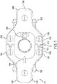
- a two part, selectively dockable robotic system 10 is provided.
- the robotic system 10 provides counterbalanced stabilization during performance of an operation (e.g., inspection, testing, cleaning, maintenance, construction, and repair) on an underwater target structure (e.g., pipe, cable, rig structure).
- the robotic system 10 includes first and second underwater robots 100, 200.
- the first and second underwater robots 100, 200 are controlled by a controller which is configured to coordinate their movements so that they cooperate and together improve the efficiency of various underwater tasks, as discussed in more detail below.
- the first underwater robot 100 includes various thrusters 102 for maneuvering the robot 100 into position with respect to the target structure T. Once the robot 100 is in position, the thrusters 102 can be used to help maintain the position of the robot 100 and also translationally move the robot 100 along the target structure T and/or rotationally move the robot 100 around the target structure T as the robot performs tasks.
- the thrusters 102 can be aligned or otherwise rotated to align along different axes of the robot (e.g., x, y, and z axis) so that the robot can move in the three-dimensions in the underwater environment.
- the target structure T is an exemplary underwater pipe.
- Other structures, such as cables, supports columns, tanks, anchoring chains, and other various marine infrastructure can be operated upon by the robot system 10; an underwater pipe is merely illustrated as an example target T.
- the first robot 100 includes a tool 104 that is used to perform work upon the target structure T.
- the tool 104 can be a waterjet capable of expelling water at a rate of speed sufficient to dislodge bio-growth and other matter from the target T.
- Other tools such as robotic arms, cleaning brushes, sensors, cameras, non-destructive inspection and testing equipment, sand blasters, welders, or other tools suitable for performing underwater inspection, testing, maintenance, cleaning, repair, or construction can also be used.
- the first underwater robot 100 can have a hull structure 106 that is sized and shaped to at least partially surround the underwater structure T.
- the underwater robot 100 can have a U-shaped hull that is sized and shaped for partially surrounding the structure T.
- a U-shape hull is particularly suited for partially surrounding cylindrical objects, such as pipes.
- the hull 106 can have other sizes and shapes that can be designed to complement the target structure T.
- the hull 106 can include arms 108 and 110 that extend outwardly to at least partially encompass the target T and extend towards the second robot 200 and support first docking mechanisms 112 to facilitate docking between the two robots 100, 200, as discussed in more detail below.
- the second underwater robot 200 can be similar to the first robot 100 in many respects.
- the second robot 200 can include a set of thrusters 202 for maneuvering into position and traversing the target structure T.
- the thrusters 202 can be aligned along different axes of the robot (e.g., x, y, and z axis) so that the robot can move in the three-dimensions in the underwater environment.
- the second robot 200 can have a hull 206 that has a similar size and shape to hull 106 of the first robot 100, including similar arms 208 and 210.
- second docking mechanisms 212 can be supported by arms 208 and 210.
- the second underwater robot 200 includes a stabilization module 204.
- the stabilization module can comprise a roller that is arranged to contact the target structure T.
- Other devices such as slides, bearings, skids, rollers, or other similar devices can be used to contact and apply a force against the target structure T.
- the stabilization module 204 provides a counterbalancing and stabilization force to the first robot 100 and the tool 104, as discussed in more detail below. Because the stabilization module 204 is in contact with the target structure T during operation of the tool 104, the stabilization module 204 can also include a sensor or other non-destructive testing equipment (e.g., camera, ultrasonic transducer, capacitive senor) that can inspect the condition of the target structure T.
- non-destructive testing equipment e.g., camera, ultrasonic transducer, capacitive senor
- the stabilization module 204 can provide a counterbalancing force and also can inspect the structure to confirm that the tool 104 has performed its operation satisfactorily or to signal when the intended operation performed by the tool is complete such that the robots 100, 200 can be removed from the target T or moved to a new location about a different target surface.
- the docking connector can include a first docking mechanism 112 supported by the first robot 100 and a second docking mechanism 212 supported by the second robot 200.
- the first docking mechanisms 112 are supported by arms 108 and 110 while and the second docking mechanism are supported by arms 208 and 210.
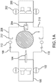
- FIG. 1A a schematic representation of the arrangement of Fig. 1 illustrates the first and second underwater robots 100, 200 coupled together in surrounding relation to the underwater target T.
- the arms 108, 110, 208, and 210 can also be configured to extend in length (e.g., telescopically) or be in the form of ropes, chains, or cable, as illustrated schematically in Fig. 1A . Accordingly, the length of the arms can be adjusted so that first and second robots 100, 200 can dock together and accommodate target structures T of various sizes and shapes. As shown in Fig.
- the first docking mechanism 112 can be a receptacle, such as a ring, that is sized and shaped to receive the second docking mechanism 212, which can comprise a hook-shaped protrusion.
- the second docking mechanism 212 can be inserted into and retained by the first docking mechanism 112 to couple the first and second robots 100, 200 together.
- Other docking mechanism arrangements can be used, such as the docking mechanisms shown in Figs. 2-4 , which are discussed in more detail below.
- the thrusters 102, 202, and stabilization module 204 can be operated as described above.
- the first and second robots When the first and second robots are coupled together via the docking mechanism they can at least partially surround the underwater target structure T.
- the first and second robots 100, 200 can be sized and shaped to cross-sectionally surround the target structure T with the target structure T disposed between the robots, as shown in Fig. 1 .
- the tool 104 is positioned for operation upon the target structure T and the stabilization mechanism 204 is positioned to provide a counterbalancing force to the forces exerted by the tool 104.
- the target structure e.g., water jet cleaning
- a force is exerted upon the target structure and an equal and opposite force is experienced by the first robot. This opposite reaction force can cause the first robot 100 to be pushed away from the target structure T.
- the first robot 100 moves out of position and away from the target structure T and is either not be able to perform its task or not able to perform the task efficiently once displaced.
- the stabilization module 204 of the second robot 200 counteracts the reaction force experienced by the first robot 100.
- the first robot 100 is held in place as it works on the target structure by the second robot 200.
- the tool 104 applies a first force against the target structure T and the stabilization module provides a second equal and opposite force that counteract the first force. Since the first and second robots 100, 200 are coupled together via the docking mechanisms, the net force experienced by the first and second robots 100, 200 is zero. The net zero force allows the robots to remain in a stable position with respect to the target structure T. Accordingly, the first and second robots and the active tool and the stabilization module work in concert to provide a stable working platform so that various operations can be performed on the target structure.
- tool 104 can be a waterjet that blasts water at high pressure against the target structure T, which can be a pipe, as shown in Fig. 1 .
- the waterjet can be directed onto the outer surface of the pipe to remove various debris, such as marine fouling and/or corrosion from the pipe surface.
- the stabilization module 204 which can comprise a roller, contacts the other side of the pipe. The force of contact between the roller and the pipe surface is equal and opposite.
- the first and second robots 100, 200 can also be coupled together so that control signals and other signals can be transmitted between the first and second robots.
- the robots can be connected via an electrical connection, which can be a part of the docking mechanism, and/or they can be connected via wireless communication modules (e.g., using Bluetooth®, near field communications, IEEE 802.11, or another communication protocol).
- wireless communication modules e.g., using Bluetooth®, near field communications, IEEE 802.11, or another communication protocol.
- Such a connection allows the robots to operate together in a coordinated-control fashion.
- the first robot moves along the target surface using its thrusters, it can provide control signals to the second robot to operate its thrusters in a complementary manner so that the first and second robots move in concert together. Accordingly, as the first robot moves along the target structure the second robot will follow and continue to provide the counterbalancing stabilization force required to maintain the robots in desired position with respect to the target structure.
- communication can be established between the surface (e.g., a surface based control station, communication relay vehicle, or support vessel) and the first and second robots.
- the communication can be established using tethers (e.g., between the surface and the first and second robots) or a wireless technology (such as acoustics, laser, visible light, RF).
- tethers e.g., between the surface and the first and second robots
- a wireless technology such as acoustics, laser, visible light, RF
- a parent-child configuration could be used where a direct connection is established between the surface and a "main robot" (e.g. the first robot 100) using a tether, while the other "support robot” (e.g., the second robot 200) is then tethered to the main robot.
- This configuration reduces the number of tethers running to the surface.
- the connection between the two robots could also be accomplished using a short range wireless technology.
- the first and second robots can be independently controlled until they dock together. After docking is completed, the first and second robots can be configured to be remotely controlled as one unit to traverse the underwater target structure longitudinally or circumferentially.
- controllers on either robot can receive separate commands from the operator (e.g. joysticks) in order to actuate the correct thrusters to achieve the motion desired by the operator.
- the operator e.g. joysticks
- one of the first and second robots e.g., support robot
- the underwater target structure e.g., pipe
- sensors e.g., sensors to automatically hold depth, orientation and/or position (using for example pressure sensor and compass).
- the operator and/or automatic controller provided by an onboard processor can also provide additional thrust force against the target structure surface to counteract recoil during docking.
- the other of the first and second robots (e.g., main robot) is remotely controlled by the operator to maneuver it within vicinity of the support vehicle to initiate docking. Docking can then be performed manually by the operator or autonomously by the onboard controller on the main vehicle using onboard cameras or sonars or any suitable sensor to guide the docking maneuver.
- the controllers on both robots can also communicate with each in order to perform automatic corrections and thereby aid in the docking.
- the two robots can be remotely controlled in this manner at the same time or one after the other.
- the operator can control the first and second robots as one unit in such way that the individual controllers associated with each of the first and second robots can exchange signals to determine which thrusters on the combined vehicle need to be actuated to achieve the desire motion by the operator including translation and rotation in any direction.
- the controllers could also unlock extra degrees of freedom by using new combinations of thruster on both vehicles to achieve certain motions not possible by one vehicle due to restrictions on available thrusters.
- controllers could automatically hold position by using the combined thrusters to correct for any longitudinal, circumferential or other displacements.
- undocking can be performed.
- the controllers can actuate their respective thrusters in opposite directions to undock.
- the controllers can also operate the docking mechanism to cause the first and second robotic vehicles to undock from each other. Independent manual control is regained over both the first and second robots after undocking is completed.
- Figures 2A-2B show the first docking mechanism 112 of the first robot 100 and the second docking mechanism 212 of the second robot 200 according to a particular embodiment.
- the first docking mechanism 112 includes a protrusion that has a conically-shaped, flared portion 150 and an elongated post 152.
- the second docking mechanism 212 includes a receptacle that has a conically-shaped, flared portion 250 and an elongated hole 252 that are sized and shaped to receive the flared portion 150 and elongated portion 152 of the first docking mechanism 112, respectively, as shown in Fig. 2B .
- the first and second robots 100, 200 are coupled together ( Fig. 2B ).
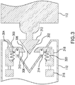
- FIG. 3 shows the first docking mechanism 112 of the first robot 100 and the second docking mechanism 212 of the second robot 200 according to a particular embodiment.
- the first docking mechanism 112 includes a wedge-shaped receptacle 300 that is sized and shaped to receive the wedge-shaped protrusion 302 of the second docking mechanism 212.
- the first docking mechanism 112 includes two mechanically operable latches 304.
- the latches 304 include a sloping face 306 that is sized and shaped to compliment a forward edge 308 of the protrusion 302. As the protrusion 302 moves toward the receptacle 300 for docking, the complimentary surface 306 and 308 allow the parts to slide past each other more efficiently.
- the latches 304 include a generally flat surface 310 on a side opposite the sloping face 306.
- the protrusion 302 includes a shoulder 312 that as sized and shaped to receive the latches 304 with the flat surface 310 disposed adjacent the shoulder 312 when the first and second docking mechanisms 112, 212 are coupled.
- the latches 304 are each supported by a pivot 314 and are connected for rotation about the pivot 314.
- An actuator 316 such as a solenoid, is connected to an arm 318 and is configured to extend and retract the arm 318 upon actuation of the actuator 316.
- the arm 318 is positioned with respect to the latch 304 to contact the latch when the actuator 316 is actuated into an extended position.
- the arm 318 includes a spring 320 that is connected to the latch 304 such that spring 320 exerts a pulling force upon the latch 304 upon retraction of the actuator 316. Since the latch is connected to the pivot 314, the actuation of the actuator 316 cause the latch 304 to rotate in both directions about the pivot 314.
- the actuator 316 can be actuated to rotate the latch 304 into a position to facilitate docking, rotated and maintained in position to maintain the robots in a docked configuration, and then rotated in an opposite direction to move the latch 304 so that the robots can decouple.
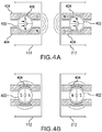
- FIGS 4A-4B illustrate the first docking mechanism 112 of the first robot 100 and the second docking mechanism 212 of the second robot 200 according to a particular embodiment.
- the docking mechanisms 112, 212 each include a motorized magnet 400, 402, respectively.
- the motorized magnets 400, 402 include a magnet having north and south poles that can be rotated so that the orientation of the north and south poles can be changed.
- Flux concentrators 404 are provided adjacent the motorized magnets 400, 402 so that the magnetic force of the magnet can be concentrated and directed toward opposing surfaces of the docking mechanisms 112, 212.
- the flux concentrators 404 can include recesses 406 that are sized and shaped to compliment the motorized magnets 400, 402 so that the space between the flux concentrators 400 and the motorized magnets 400, 402 can be minimized, thereby increasing the effectiveness of the flux concentrators.
- the motorized magnets 400, 402 are oriented so that the poles are directed towards the flux concentrators 404.
- Motorized magnet 400 is oriented with its poles opposite the poles of motorized magnet 402. Accordingly, in this configuration, the docking mechanisms 112 and 212 experience an attractive magnetic force that facilitates and maintains coupling between the first and second robots 100, 200.
- the motorized magnets 400, 402 are rotated so that the poles are not directed toward the flux concentrators 404 and opposite poles are directed toward each other, as shown in Fig. 4B .
- the motorized magnets 400, 402 can be rotated with the poles directed towards the flux concentrators 404 with the same pole orientation, causing a repulsive, decoupling force to be directed through the flux concentrators 404.
- the robots 100, 200 have been described as each having a tool 104 and a stabilization module 204, respectively, the tool 104 can be associated with the robot 100 and the stabilization module can be associated with the robot 200, as the robots described herein are otherwise the same, save for having complementary docking connector D features.
- the tools, stabilization module, and/or docking connector features can be supported one or the other of the first and second robots.
- the first robot can be the "main robot” and the second robot can be the "support robot” and vise-a-versa.
- each of the robots 100, 200 can be provided with both a tool and a stabilization module, substantially as described above in connection with Fig.
- the particular tool and stabilization module construction included with a particular robot 100, 200 can be the same as included on the other robot, or different. By providing different tools on each of the robots 100, 200, a greater range of operations can be performed while the robots are underwater.
- the robots 100, 200 can include a tether and/or the robots can be docked with each other with a rope or chain. As the robots perform operation (cleaning and/or inspection) on the underwater target structure (e.g., helical sweep cleaning/inspection pattern) the tether/rope can wrap around the target structure. Once the operation is complete, the robots can perform a reverse maneuver that unwraps the tether/rope while also performing a second operation (cleaning and/or inspection).
- one or more computer programs, modules, and/or applications that when executed perform methods of the present disclosure need not reside on a single computer or processor, but can be distributed in a modular fashion amongst a number of different computers or processors to implement various aspects of the systems and methods disclosed herein.
Landscapes
- Engineering & Computer Science (AREA)
- Mechanical Engineering (AREA)
- General Engineering & Computer Science (AREA)
- Robotics (AREA)
- Physics & Mathematics (AREA)
- Life Sciences & Earth Sciences (AREA)
- Ocean & Marine Engineering (AREA)
- Chemical & Material Sciences (AREA)
- Aviation & Aerospace Engineering (AREA)
- General Physics & Mathematics (AREA)
- General Health & Medical Sciences (AREA)
- Immunology (AREA)
- Pathology (AREA)
- Health & Medical Sciences (AREA)
- Analytical Chemistry (AREA)
- Biochemistry (AREA)
- Mining & Mineral Resources (AREA)
- Geology (AREA)
- Quality & Reliability (AREA)
- Combustion & Propulsion (AREA)
- Environmental & Geological Engineering (AREA)
- Fluid Mechanics (AREA)
- Geochemistry & Mineralogy (AREA)
- General Life Sciences & Earth Sciences (AREA)
- Acoustics & Sound (AREA)
- Manipulator (AREA)
- Control Of Position, Course, Altitude, Or Attitude Of Moving Bodies (AREA)
Applications Claiming Priority (3)
| Application Number | Priority Date | Filing Date | Title |
|---|---|---|---|
| US201662397175P | 2016-09-20 | 2016-09-20 | |
| US15/684,102 US10124494B2 (en) | 2016-09-20 | 2017-08-23 | Coordinated water environment mobile robots |
| PCT/US2017/051141 WO2018057344A1 (en) | 2016-09-20 | 2017-09-12 | Coordinated water environment mobile robots |
Publications (2)
| Publication Number | Publication Date |
|---|---|
| EP3516280A1 EP3516280A1 (en) | 2019-07-31 |
| EP3516280B1 true EP3516280B1 (en) | 2020-05-13 |
Family
ID=59982481
Family Applications (1)
| Application Number | Title | Priority Date | Filing Date |
|---|---|---|---|
| EP17777445.2A Active EP3516280B1 (en) | 2016-09-20 | 2017-09-12 | Coordinated water environment mobile robots |
Country Status (9)
| Country | Link |
|---|---|
| US (2) | US10124494B2 (enExample) |
| EP (1) | EP3516280B1 (enExample) |
| JP (1) | JP2019531962A (enExample) |
| KR (1) | KR20190051025A (enExample) |
| CN (1) | CN109716004B (enExample) |
| ES (1) | ES2802477T3 (enExample) |
| SA (1) | SA519401269B1 (enExample) |
| SG (1) | SG10202008081UA (enExample) |
| WO (1) | WO2018057344A1 (enExample) |
Families Citing this family (40)
| Publication number | Priority date | Publication date | Assignee | Title |
|---|---|---|---|---|
| US10124494B2 (en) * | 2016-09-20 | 2018-11-13 | Saudi Arabian Oil Company | Coordinated water environment mobile robots |
| CN108820166B (zh) * | 2018-05-07 | 2019-12-10 | 吉林大学 | 一种可重构铰接式水下机器人 |
| US10730080B1 (en) * | 2019-02-28 | 2020-08-04 | United States Of America As Represented By Secretary Of The Navy | Low-power cleaning of underwater cable/array |
| US11608148B2 (en) | 2019-04-05 | 2023-03-21 | Fmc Technologies, Inc. | Submersible remote operated vehicle tool change control |
| CN109985875B (zh) * | 2019-05-08 | 2021-09-24 | 浙江海洋大学 | 一种智能网箱清洗修补机器人及使用方法 |
| US11505283B1 (en) | 2019-09-12 | 2022-11-22 | The United States Of America As Represented By The Secretary Of The Navy | Apparatus for coupling and positioning elements on a configurable vehicle |
| US11511836B1 (en) * | 2019-09-12 | 2022-11-29 | The United States Of America As Represented By The Secretary Of The Navy | Field configurable spherical underwater vehicle |
| US11530019B1 (en) | 2019-09-12 | 2022-12-20 | The United States Of America As Represented By The Secretary Of The Navy | Propulsion system for field configurable vehicle |
| US11745840B1 (en) * | 2019-09-12 | 2023-09-05 | The United States Of America As Represented By The Secretary Of The Navy | Apparatus and method for joining modules in a field configurable autonomous vehicle |
| US11505296B1 (en) | 2019-09-12 | 2022-11-22 | The United States Of America As Represented By The Secretary Of The Navy | Method and apparatus for transporting ballast and cargo in an autonomous vehicle |
| US11530017B1 (en) | 2019-09-12 | 2022-12-20 | The United States Of America As Represented By The Secretary Of The Navy | Scuttle module for field configurable vehicle |
| US11608149B1 (en) | 2019-09-12 | 2023-03-21 | The United States Of America As Represented By The Secretary Of The Navy | Buoyancy control module for field configurable autonomous vehicle |
| US11541801B1 (en) | 2019-09-12 | 2023-01-03 | The United States Of America As Represented By The Secretary Of The Navy | Method and apparatus for positioning the center of mass on an unmanned underwater vehicle |
| US11760454B1 (en) | 2019-09-12 | 2023-09-19 | The United States Of America As Represented By The Secretary Of The Navy | Methods of forming field configurable underwater vehicles |
| US11904993B1 (en) | 2019-09-12 | 2024-02-20 | The United States Of America As Represented By The Secretary Of The Navy | Supplemental techniques for vehicle and module thermal management |
| US12244352B1 (en) | 2019-09-12 | 2025-03-04 | The United States Of America As Represented By The Secretary Of The Navy | Optical communications for autonomous vehicles |
| US12454338B1 (en) | 2019-09-12 | 2025-10-28 | The United States Of America As Represented By The Secretary Of The Navy | Field configurable autonomous vehicle |
| US11603170B1 (en) | 2019-10-03 | 2023-03-14 | The United States Of America As Represented By The Secretary Of The Navy | Method for parasitic transport of an autonomous vehicle |
| CN110884632B (zh) * | 2019-11-13 | 2021-04-27 | 浙江大学 | 一种应用于混合式垂直剖面仪的接驳系统 |
| GB2607235B (en) * | 2019-12-27 | 2023-05-24 | Kawasaki Heavy Ind Ltd | Underwater docking system, underwater vehicle and underwater station |
| CN111152209B (zh) * | 2020-01-09 | 2022-07-19 | 吉林大学 | 线驱动仿生软体机械手 |
| KR102322097B1 (ko) * | 2020-05-21 | 2021-11-03 | 한국로봇융합연구원 | 가변 구조를 갖는 수중 로봇 |
| CN111878713B (zh) * | 2020-08-03 | 2022-06-24 | 广东华泰检测科技有限公司 | 一种探伤仪检测固定装置 |
| CN112078686B (zh) * | 2020-09-09 | 2022-04-08 | 哈尔滨工业大学 | 一种水下探测机器人 |
| CN114537626B (zh) * | 2020-11-24 | 2022-12-20 | 中国科学院沈阳自动化研究所 | 一种水下机器人自主坐底控制方法 |
| CN112793742B (zh) * | 2021-01-12 | 2022-05-06 | 浙江理工大学 | 一种仿皮皮虾水下机器人 |
| CN112793743B (zh) * | 2021-01-12 | 2021-12-07 | 浙江理工大学 | 一种模块化的水下仿生蹼式机器人 |
| EP4281359A2 (en) * | 2021-01-22 | 2023-11-29 | Agellus Tankbot 360 Inc. | Robotic modular submersible device and methods |
| US12296694B2 (en) | 2021-03-10 | 2025-05-13 | Techtronic Cordless Gp | Lawnmowers |
| CN113752238A (zh) * | 2021-09-07 | 2021-12-07 | 灵起科技(深圳)有限公司 | 一种两只桌面宠物机器人之间近距离搜索的方法 |
| AU2022268338A1 (en) | 2021-11-10 | 2023-05-25 | Techtronic Cordless Gp | Robotic lawn mowers |
| CN114669933B (zh) * | 2022-03-29 | 2023-05-16 | 河海大学 | 一种水下焊接机器人及其运行工艺 |
| CN114789784A (zh) * | 2022-04-14 | 2022-07-26 | 青岛澎湃海洋探索技术有限公司 | 水下机器人用主动式抛载装置 |
| US12472611B2 (en) | 2022-05-31 | 2025-11-18 | Techtronic Cordless Gp | Peg driver |
| EP4310621B1 (en) | 2022-07-19 | 2025-02-12 | Techtronic Cordless GP | Display for controlling robotic tool |
| AU2023206123A1 (en) | 2022-07-29 | 2024-02-15 | Techtronic Cordless Gp | Generation of a cryptography key for a robotic garden tool |
| US11807349B1 (en) | 2022-09-16 | 2023-11-07 | Fmc Technologies, Inc. | Submersible remote operated vehicle vision assistance and control |
| CN115475808B (zh) * | 2022-09-20 | 2023-08-18 | 中国水产科学研究院东海水产研究所 | 一种深远海大型养殖平台用水下网衣清洗机器人 |
| CN115959270B (zh) * | 2023-01-05 | 2025-04-18 | 中国科学院沈阳自动化研究所 | 一种用于深海作业工具对接的压紧自锁机构 |
| CN118254202B (zh) * | 2024-05-28 | 2024-08-13 | 济宁市质量计量检验检测研究院(济宁半导体及显示产品质量监督检验中心、济宁市纤维质量监测中心) | 一种水下管道无损检测拉手机器人及方法 |
Family Cites Families (27)
| Publication number | Priority date | Publication date | Assignee | Title |
|---|---|---|---|---|
| US2427129A (en) | 1943-07-10 | 1947-09-09 | Fields Donald Albert | Exterior pipe surface brushing machine |
| US2657409A (en) | 1949-05-06 | 1953-11-03 | Robert A J Dawson | Rowel type pipe cleaning tool |
| US2787051A (en) | 1952-09-26 | 1957-04-02 | Dresser Ind | Method of installing fittings upon submerged pipe |
| GB957180A (en) | 1960-08-15 | 1964-05-06 | Purdie Decolsing Ltd W | Apparatus for surface-treating tubes, pipes, or the like |
| GB2027473A (en) | 1978-07-28 | 1980-02-20 | Boc Ltd | Apparatus for attachment to tubular or elongate structural members |
| AU1610283A (en) | 1982-06-23 | 1984-01-05 | Maxwell Graham Begley | Conduit clamp |
| NL8203501A (nl) | 1982-09-08 | 1984-04-02 | Dirk Frans Van Voskuilen En Fr | Werkwijze en inrichting voor het debitumineren of verwijderen van een ander-soortige bekleding, zoals een bekleding van polyethyleen, van een buis. |
| WO1986006696A1 (en) | 1985-05-03 | 1986-11-20 | Dawson Offshore Pty. Ltd. | Remote operated machine for cleaning, inspection and maintenance of underwater structures |
| US4880335A (en) | 1987-08-21 | 1989-11-14 | Arabian American Oil Company | Method and apparatus for removing concrete coating from pipe |
| GB8802369D0 (en) | 1988-02-03 | 1988-03-02 | Amerada Hess Ltd | Subsea vehicle |
| US5626438A (en) | 1993-01-15 | 1997-05-06 | Pipeline Rehab, Inc. | System for excavating and rehabilitating underground pipelines |
| US5435405A (en) | 1993-05-14 | 1995-07-25 | Carnegie Mellon University | Reconfigurable mobile vehicle with magnetic tracks |
| JPH08290131A (ja) * | 1995-04-20 | 1996-11-05 | Mitsubishi Heavy Ind Ltd | 水中清掃ロボットの清掃機構 |
| GB9903574D0 (en) | 1999-02-18 | 1999-04-07 | Subsea Offshore Ltd | Connector |
| US6523629B1 (en) | 1999-06-07 | 2003-02-25 | Sandia Corporation | Tandem mobile robot system |
| US6167831B1 (en) | 1999-09-20 | 2001-01-02 | Coflexip S.A. | Underwater vehicle |
| US7000560B2 (en) | 2003-12-11 | 2006-02-21 | Honeywell International, Inc. | Unmanned underwater vehicle docking station coupling system and method |
| NO329288B1 (no) | 2007-12-21 | 2010-09-27 | Fmc Kongsberg Subsea As | Verktoy og metode for forbindelse av rorledninger |
| US7992508B1 (en) | 2008-04-21 | 2011-08-09 | Norton Daniel A | Remotely operated watercraft docking mechanism having fuel saving and theft thwarting attributes |
| US7656997B1 (en) | 2008-09-15 | 2010-02-02 | VJ Technologies | Method and apparatus for automated, digital, radiographic inspection of piping |
| US8619134B2 (en) | 2009-03-11 | 2013-12-31 | Seatrepid International, Llc | Unmanned apparatus traversal and inspection system |
| GB201102784D0 (en) | 2011-02-17 | 2011-03-30 | Stats Uk Ltd | Pipe sealing |
| US9004200B2 (en) | 2011-09-09 | 2015-04-14 | Pinhas Ben-Tzvi | Mobile robot with hybrid traction and mobility mechanism |
| JP5806568B2 (ja) | 2011-09-26 | 2015-11-10 | 川崎重工業株式会社 | 水中移動型検査装置及び水中検査設備 |
| JP6143132B2 (ja) * | 2012-10-08 | 2017-06-07 | コリア インスティチュート オブ インダストリアル テクノロジー | 水中ロボットのドッキングステーション |
| KR101621143B1 (ko) | 2014-06-19 | 2016-05-16 | 포항공과대학교 산학협력단 | 수중 에이전트 도킹 시스템 및 이를 이용한 도킹방법 |
| US10124494B2 (en) * | 2016-09-20 | 2018-11-13 | Saudi Arabian Oil Company | Coordinated water environment mobile robots |
-
2017
- 2017-08-23 US US15/684,102 patent/US10124494B2/en active Active
- 2017-09-12 JP JP2019515589A patent/JP2019531962A/ja active Pending
- 2017-09-12 KR KR1020197010255A patent/KR20190051025A/ko not_active Abandoned
- 2017-09-12 WO PCT/US2017/051141 patent/WO2018057344A1/en not_active Ceased
- 2017-09-12 EP EP17777445.2A patent/EP3516280B1/en active Active
- 2017-09-12 CN CN201780057567.4A patent/CN109716004B/zh not_active Expired - Fee Related
- 2017-09-12 SG SG10202008081UA patent/SG10202008081UA/en unknown
- 2017-09-12 ES ES17777445T patent/ES2802477T3/es active Active
-
2018
- 2018-10-05 US US16/153,295 patent/US10456924B2/en active Active
-
2019
- 2019-03-11 SA SA519401269A patent/SA519401269B1/ar unknown
Non-Patent Citations (1)
| Title |
|---|
| None * |
Also Published As
| Publication number | Publication date |
|---|---|
| SA519401269B1 (ar) | 2021-12-14 |
| JP2019531962A (ja) | 2019-11-07 |
| US10124494B2 (en) | 2018-11-13 |
| WO2018057344A1 (en) | 2018-03-29 |
| CN109716004A (zh) | 2019-05-03 |
| US10456924B2 (en) | 2019-10-29 |
| SG10202008081UA (en) | 2020-10-29 |
| ES2802477T3 (es) | 2021-01-19 |
| KR20190051025A (ko) | 2019-05-14 |
| CN109716004B (zh) | 2021-02-02 |
| US20180080307A1 (en) | 2018-03-22 |
| US20190039251A1 (en) | 2019-02-07 |
| EP3516280A1 (en) | 2019-07-31 |
Similar Documents
| Publication | Publication Date | Title |
|---|---|---|
| US10456924B2 (en) | Coordinated, complementary water environment mobile robots | |
| AU2016212374B2 (en) | Underwater manipulator arm robot | |
| US10272980B2 (en) | Underwater vehicles and inspection methods | |
| EP3271240B1 (en) | Communications among water environment mobile robots | |
| EP4005917B1 (en) | Underwater mobile inspection apparatus and underwater inspection equipment | |
| EP3110690B1 (en) | Subsea hosting of unmanned underwater vehicles | |
| KR101323824B1 (ko) | 수중 로봇 운용 장치 | |
| EP3774523B1 (en) | Communication with unmanned underwater vehicles | |
| EP3947902B1 (en) | Submersible remote operated vehicle tool change control | |
| NO20190196A1 (en) | Launch Platform for an unmanned vehicle | |
| CN110395369A (zh) | 一种基于磁轮行走的水下钢结构表面海生物清洗机器人 | |
| CN116812116A (zh) | 一种水下结构清洗检测作业机器人 | |
| FR3013314A1 (fr) | Dispositif de maintenance et de reperage d'une flute sismique | |
| US20220412193A1 (en) | Device of Remotely Operated, Tethered, Subsea Tools and Method of Launching Such Tools | |
| HK40080861A (en) | In-pipe robot and system | |
| HK40037250A (en) | In-pipe robot and system | |
| HK40037250B (en) | In-pipe robot and system | |
| CN110341911A (zh) | 水下钢结构表面海生物清洗机器人及成像系统的控制方法 |
Legal Events
| Date | Code | Title | Description |
|---|---|---|---|
| STAA | Information on the status of an ep patent application or granted ep patent |
Free format text: STATUS: UNKNOWN |
|
| STAA | Information on the status of an ep patent application or granted ep patent |
Free format text: STATUS: THE INTERNATIONAL PUBLICATION HAS BEEN MADE |
|
| PUAI | Public reference made under article 153(3) epc to a published international application that has entered the european phase |
Free format text: ORIGINAL CODE: 0009012 |
|
| STAA | Information on the status of an ep patent application or granted ep patent |
Free format text: STATUS: REQUEST FOR EXAMINATION WAS MADE |
|
| 17P | Request for examination filed |
Effective date: 20190404 |
|
| AK | Designated contracting states |
Kind code of ref document: A1 Designated state(s): AL AT BE BG CH CY CZ DE DK EE ES FI FR GB GR HR HU IE IS IT LI LT LU LV MC MK MT NL NO PL PT RO RS SE SI SK SM TR |
|
| AX | Request for extension of the european patent |
Extension state: BA ME |
|
| DAV | Request for validation of the european patent (deleted) | ||
| DAX | Request for extension of the european patent (deleted) | ||
| GRAP | Despatch of communication of intention to grant a patent |
Free format text: ORIGINAL CODE: EPIDOSNIGR1 |
|
| STAA | Information on the status of an ep patent application or granted ep patent |
Free format text: STATUS: GRANT OF PATENT IS INTENDED |
|
| INTG | Intention to grant announced |
Effective date: 20200129 |
|
| GRAS | Grant fee paid |
Free format text: ORIGINAL CODE: EPIDOSNIGR3 |
|
| GRAA | (expected) grant |
Free format text: ORIGINAL CODE: 0009210 |
|
| STAA | Information on the status of an ep patent application or granted ep patent |
Free format text: STATUS: THE PATENT HAS BEEN GRANTED |
|
| AK | Designated contracting states |
Kind code of ref document: B1 Designated state(s): AL AT BE BG CH CY CZ DE DK EE ES FI FR GB GR HR HU IE IS IT LI LT LU LV MC MK MT NL NO PL PT RO RS SE SI SK SM TR |
|
| REG | Reference to a national code |
Ref country code: GB Ref legal event code: FG4D |
|
| REG | Reference to a national code |
Ref country code: CH Ref legal event code: EP |
|
| REG | Reference to a national code |
Ref country code: CH Ref legal event code: NV Representative=s name: RENTSCH PARTNER AG, CH |
|
| REG | Reference to a national code |
Ref country code: DE Ref legal event code: R096 Ref document number: 602017016776 Country of ref document: DE |
|
| REG | Reference to a national code |
Ref country code: AT Ref legal event code: REF Ref document number: 1270736 Country of ref document: AT Kind code of ref document: T Effective date: 20200615 |
|
| REG | Reference to a national code |
Ref country code: NO Ref legal event code: T2 Effective date: 20200513 |
|
| REG | Reference to a national code |
Ref country code: NL Ref legal event code: FP |
|
| REG | Reference to a national code |
Ref country code: LT Ref legal event code: MG4D |
|
| PG25 | Lapsed in a contracting state [announced via postgrant information from national office to epo] |
Ref country code: SE Free format text: LAPSE BECAUSE OF FAILURE TO SUBMIT A TRANSLATION OF THE DESCRIPTION OR TO PAY THE FEE WITHIN THE PRESCRIBED TIME-LIMIT Effective date: 20200513 Ref country code: LT Free format text: LAPSE BECAUSE OF FAILURE TO SUBMIT A TRANSLATION OF THE DESCRIPTION OR TO PAY THE FEE WITHIN THE PRESCRIBED TIME-LIMIT Effective date: 20200513 Ref country code: IS Free format text: LAPSE BECAUSE OF FAILURE TO SUBMIT A TRANSLATION OF THE DESCRIPTION OR TO PAY THE FEE WITHIN THE PRESCRIBED TIME-LIMIT Effective date: 20200913 Ref country code: PT Free format text: LAPSE BECAUSE OF FAILURE TO SUBMIT A TRANSLATION OF THE DESCRIPTION OR TO PAY THE FEE WITHIN THE PRESCRIBED TIME-LIMIT Effective date: 20200914 Ref country code: FI Free format text: LAPSE BECAUSE OF FAILURE TO SUBMIT A TRANSLATION OF THE DESCRIPTION OR TO PAY THE FEE WITHIN THE PRESCRIBED TIME-LIMIT Effective date: 20200513 Ref country code: GR Free format text: LAPSE BECAUSE OF FAILURE TO SUBMIT A TRANSLATION OF THE DESCRIPTION OR TO PAY THE FEE WITHIN THE PRESCRIBED TIME-LIMIT Effective date: 20200814 |
|
| PG25 | Lapsed in a contracting state [announced via postgrant information from national office to epo] |
Ref country code: RS Free format text: LAPSE BECAUSE OF FAILURE TO SUBMIT A TRANSLATION OF THE DESCRIPTION OR TO PAY THE FEE WITHIN THE PRESCRIBED TIME-LIMIT Effective date: 20200513 Ref country code: BG Free format text: LAPSE BECAUSE OF FAILURE TO SUBMIT A TRANSLATION OF THE DESCRIPTION OR TO PAY THE FEE WITHIN THE PRESCRIBED TIME-LIMIT Effective date: 20200813 Ref country code: HR Free format text: LAPSE BECAUSE OF FAILURE TO SUBMIT A TRANSLATION OF THE DESCRIPTION OR TO PAY THE FEE WITHIN THE PRESCRIBED TIME-LIMIT Effective date: 20200513 Ref country code: LV Free format text: LAPSE BECAUSE OF FAILURE TO SUBMIT A TRANSLATION OF THE DESCRIPTION OR TO PAY THE FEE WITHIN THE PRESCRIBED TIME-LIMIT Effective date: 20200513 |
|
| REG | Reference to a national code |
Ref country code: AT Ref legal event code: MK05 Ref document number: 1270736 Country of ref document: AT Kind code of ref document: T Effective date: 20200513 |
|
| PG25 | Lapsed in a contracting state [announced via postgrant information from national office to epo] |
Ref country code: AL Free format text: LAPSE BECAUSE OF FAILURE TO SUBMIT A TRANSLATION OF THE DESCRIPTION OR TO PAY THE FEE WITHIN THE PRESCRIBED TIME-LIMIT Effective date: 20200513 |
|
| REG | Reference to a national code |
Ref country code: ES Ref legal event code: FG2A Ref document number: 2802477 Country of ref document: ES Kind code of ref document: T3 Effective date: 20210119 |
|
| PG25 | Lapsed in a contracting state [announced via postgrant information from national office to epo] |
Ref country code: RO Free format text: LAPSE BECAUSE OF FAILURE TO SUBMIT A TRANSLATION OF THE DESCRIPTION OR TO PAY THE FEE WITHIN THE PRESCRIBED TIME-LIMIT Effective date: 20200513 Ref country code: CZ Free format text: LAPSE BECAUSE OF FAILURE TO SUBMIT A TRANSLATION OF THE DESCRIPTION OR TO PAY THE FEE WITHIN THE PRESCRIBED TIME-LIMIT Effective date: 20200513 Ref country code: SM Free format text: LAPSE BECAUSE OF FAILURE TO SUBMIT A TRANSLATION OF THE DESCRIPTION OR TO PAY THE FEE WITHIN THE PRESCRIBED TIME-LIMIT Effective date: 20200513 Ref country code: EE Free format text: LAPSE BECAUSE OF FAILURE TO SUBMIT A TRANSLATION OF THE DESCRIPTION OR TO PAY THE FEE WITHIN THE PRESCRIBED TIME-LIMIT Effective date: 20200513 Ref country code: AT Free format text: LAPSE BECAUSE OF FAILURE TO SUBMIT A TRANSLATION OF THE DESCRIPTION OR TO PAY THE FEE WITHIN THE PRESCRIBED TIME-LIMIT Effective date: 20200513 Ref country code: DK Free format text: LAPSE BECAUSE OF FAILURE TO SUBMIT A TRANSLATION OF THE DESCRIPTION OR TO PAY THE FEE WITHIN THE PRESCRIBED TIME-LIMIT Effective date: 20200513 |
|
| REG | Reference to a national code |
Ref country code: DE Ref legal event code: R097 Ref document number: 602017016776 Country of ref document: DE |
|
| PG25 | Lapsed in a contracting state [announced via postgrant information from national office to epo] |
Ref country code: SK Free format text: LAPSE BECAUSE OF FAILURE TO SUBMIT A TRANSLATION OF THE DESCRIPTION OR TO PAY THE FEE WITHIN THE PRESCRIBED TIME-LIMIT Effective date: 20200513 Ref country code: PL Free format text: LAPSE BECAUSE OF FAILURE TO SUBMIT A TRANSLATION OF THE DESCRIPTION OR TO PAY THE FEE WITHIN THE PRESCRIBED TIME-LIMIT Effective date: 20200513 |
|
| PLBE | No opposition filed within time limit |
Free format text: ORIGINAL CODE: 0009261 |
|
| STAA | Information on the status of an ep patent application or granted ep patent |
Free format text: STATUS: NO OPPOSITION FILED WITHIN TIME LIMIT |
|
| 26N | No opposition filed |
Effective date: 20210216 |
|
| REG | Reference to a national code |
Ref country code: BE Ref legal event code: MM Effective date: 20200930 |
|
| PG25 | Lapsed in a contracting state [announced via postgrant information from national office to epo] |
Ref country code: LU Free format text: LAPSE BECAUSE OF NON-PAYMENT OF DUE FEES Effective date: 20200912 |
|
| PG25 | Lapsed in a contracting state [announced via postgrant information from national office to epo] |
Ref country code: IE Free format text: LAPSE BECAUSE OF NON-PAYMENT OF DUE FEES Effective date: 20200912 Ref country code: BE Free format text: LAPSE BECAUSE OF NON-PAYMENT OF DUE FEES Effective date: 20200930 |
|
| PGFP | Annual fee paid to national office [announced via postgrant information from national office to epo] |
Ref country code: IT Payment date: 20210910 Year of fee payment: 5 Ref country code: NL Payment date: 20210913 Year of fee payment: 5 Ref country code: CH Payment date: 20210923 Year of fee payment: 5 Ref country code: FR Payment date: 20210909 Year of fee payment: 5 |
|
| PGFP | Annual fee paid to national office [announced via postgrant information from national office to epo] |
Ref country code: NO Payment date: 20210907 Year of fee payment: 5 Ref country code: GB Payment date: 20210910 Year of fee payment: 5 Ref country code: DE Payment date: 20210930 Year of fee payment: 5 |
|
| PGFP | Annual fee paid to national office [announced via postgrant information from national office to epo] |
Ref country code: ES Payment date: 20211015 Year of fee payment: 5 |
|
| PG25 | Lapsed in a contracting state [announced via postgrant information from national office to epo] |
Ref country code: TR Free format text: LAPSE BECAUSE OF FAILURE TO SUBMIT A TRANSLATION OF THE DESCRIPTION OR TO PAY THE FEE WITHIN THE PRESCRIBED TIME-LIMIT Effective date: 20200513 Ref country code: MT Free format text: LAPSE BECAUSE OF FAILURE TO SUBMIT A TRANSLATION OF THE DESCRIPTION OR TO PAY THE FEE WITHIN THE PRESCRIBED TIME-LIMIT Effective date: 20200513 Ref country code: CY Free format text: LAPSE BECAUSE OF FAILURE TO SUBMIT A TRANSLATION OF THE DESCRIPTION OR TO PAY THE FEE WITHIN THE PRESCRIBED TIME-LIMIT Effective date: 20200513 |
|
| PG25 | Lapsed in a contracting state [announced via postgrant information from national office to epo] |
Ref country code: MK Free format text: LAPSE BECAUSE OF FAILURE TO SUBMIT A TRANSLATION OF THE DESCRIPTION OR TO PAY THE FEE WITHIN THE PRESCRIBED TIME-LIMIT Effective date: 20200513 Ref country code: MC Free format text: LAPSE BECAUSE OF FAILURE TO SUBMIT A TRANSLATION OF THE DESCRIPTION OR TO PAY THE FEE WITHIN THE PRESCRIBED TIME-LIMIT Effective date: 20200513 |
|
| REG | Reference to a national code |
Ref country code: DE Ref legal event code: R119 Ref document number: 602017016776 Country of ref document: DE |
|
| REG | Reference to a national code |
Ref country code: NO Ref legal event code: MMEP |
|
| REG | Reference to a national code |
Ref country code: CH Ref legal event code: PL |
|
| REG | Reference to a national code |
Ref country code: NL Ref legal event code: MM Effective date: 20221001 |
|
| GBPC | Gb: european patent ceased through non-payment of renewal fee |
Effective date: 20220912 |
|
| PG25 | Lapsed in a contracting state [announced via postgrant information from national office to epo] |
Ref country code: NL Free format text: LAPSE BECAUSE OF NON-PAYMENT OF DUE FEES Effective date: 20221001 |
|
| PG25 | Lapsed in a contracting state [announced via postgrant information from national office to epo] |
Ref country code: NO Free format text: LAPSE BECAUSE OF NON-PAYMENT OF DUE FEES Effective date: 20220930 Ref country code: LI Free format text: LAPSE BECAUSE OF NON-PAYMENT OF DUE FEES Effective date: 20220930 Ref country code: FR Free format text: LAPSE BECAUSE OF NON-PAYMENT OF DUE FEES Effective date: 20220930 Ref country code: DE Free format text: LAPSE BECAUSE OF NON-PAYMENT OF DUE FEES Effective date: 20230401 Ref country code: CH Free format text: LAPSE BECAUSE OF NON-PAYMENT OF DUE FEES Effective date: 20220930 |
|
| PG25 | Lapsed in a contracting state [announced via postgrant information from national office to epo] |
Ref country code: SI Free format text: LAPSE BECAUSE OF FAILURE TO SUBMIT A TRANSLATION OF THE DESCRIPTION OR TO PAY THE FEE WITHIN THE PRESCRIBED TIME-LIMIT Effective date: 20200513 |
|
| REG | Reference to a national code |
Ref country code: ES Ref legal event code: FD2A Effective date: 20231027 |
|
| PG25 | Lapsed in a contracting state [announced via postgrant information from national office to epo] |
Ref country code: IT Free format text: LAPSE BECAUSE OF NON-PAYMENT OF DUE FEES Effective date: 20220912 Ref country code: GB Free format text: LAPSE BECAUSE OF NON-PAYMENT OF DUE FEES Effective date: 20220912 |
|
| PG25 | Lapsed in a contracting state [announced via postgrant information from national office to epo] |
Ref country code: ES Free format text: LAPSE BECAUSE OF NON-PAYMENT OF DUE FEES Effective date: 20220913 |
|
| PG25 | Lapsed in a contracting state [announced via postgrant information from national office to epo] |
Ref country code: ES Free format text: LAPSE BECAUSE OF NON-PAYMENT OF DUE FEES Effective date: 20220913 |